EP4174339B1 - Disc brake, brake pad and brake system comprising the disc brake and brake pads - Google Patents
Disc brake, brake pad and brake system comprising the disc brake and brake pads Download PDFInfo
- Publication number
- EP4174339B1 EP4174339B1 EP21204888.8A EP21204888A EP4174339B1 EP 4174339 B1 EP4174339 B1 EP 4174339B1 EP 21204888 A EP21204888 A EP 21204888A EP 4174339 B1 EP4174339 B1 EP 4174339B1
- Authority
- EP
- European Patent Office
- Prior art keywords
- brake
- disc
- channels
- caliper
- lining
- Prior art date
- Legal status (The legal status is an assumption and is not a legal conclusion. Google has not performed a legal analysis and makes no representation as to the accuracy of the status listed.)
- Active
Links
Images

Classifications
-
- F—MECHANICAL ENGINEERING; LIGHTING; HEATING; WEAPONS; BLASTING
- F16—ENGINEERING ELEMENTS AND UNITS; GENERAL MEASURES FOR PRODUCING AND MAINTAINING EFFECTIVE FUNCTIONING OF MACHINES OR INSTALLATIONS; THERMAL INSULATION IN GENERAL
- F16D—COUPLINGS FOR TRANSMITTING ROTATION; CLUTCHES; BRAKES
- F16D65/00—Parts or details
- F16D65/0031—Devices for retaining friction material debris, e.g. dust collectors or filters
-
- F—MECHANICAL ENGINEERING; LIGHTING; HEATING; WEAPONS; BLASTING
- F16—ENGINEERING ELEMENTS AND UNITS; GENERAL MEASURES FOR PRODUCING AND MAINTAINING EFFECTIVE FUNCTIONING OF MACHINES OR INSTALLATIONS; THERMAL INSULATION IN GENERAL
- F16D—COUPLINGS FOR TRANSMITTING ROTATION; CLUTCHES; BRAKES
- F16D55/00—Brakes with substantially-radial braking surfaces pressed together in axial direction, e.g. disc brakes
- F16D55/02—Brakes with substantially-radial braking surfaces pressed together in axial direction, e.g. disc brakes with axially-movable discs or pads pressed against axially-located rotating members
- F16D55/22—Brakes with substantially-radial braking surfaces pressed together in axial direction, e.g. disc brakes with axially-movable discs or pads pressed against axially-located rotating members by clamping an axially-located rotating disc between movable braking members, e.g. movable brake discs or brake pads
- F16D55/224—Brakes with substantially-radial braking surfaces pressed together in axial direction, e.g. disc brakes with axially-movable discs or pads pressed against axially-located rotating members by clamping an axially-located rotating disc between movable braking members, e.g. movable brake discs or brake pads with a common actuating member for the braking members
- F16D55/225—Brakes with substantially-radial braking surfaces pressed together in axial direction, e.g. disc brakes with axially-movable discs or pads pressed against axially-located rotating members by clamping an axially-located rotating disc between movable braking members, e.g. movable brake discs or brake pads with a common actuating member for the braking members the braking members being brake pads
- F16D55/226—Brakes with substantially-radial braking surfaces pressed together in axial direction, e.g. disc brakes with axially-movable discs or pads pressed against axially-located rotating members by clamping an axially-located rotating disc between movable braking members, e.g. movable brake discs or brake pads with a common actuating member for the braking members the braking members being brake pads in which the common actuating member is moved axially, e.g. floating caliper disc brakes
-
- F—MECHANICAL ENGINEERING; LIGHTING; HEATING; WEAPONS; BLASTING
- F16—ENGINEERING ELEMENTS AND UNITS; GENERAL MEASURES FOR PRODUCING AND MAINTAINING EFFECTIVE FUNCTIONING OF MACHINES OR INSTALLATIONS; THERMAL INSULATION IN GENERAL
- F16D—COUPLINGS FOR TRANSMITTING ROTATION; CLUTCHES; BRAKES
- F16D69/00—Friction linings; Attachment thereof; Selection of coacting friction substances or surfaces
- F16D2069/004—Profiled friction surfaces, e.g. grooves, dimples
-
- F—MECHANICAL ENGINEERING; LIGHTING; HEATING; WEAPONS; BLASTING
- F16—ENGINEERING ELEMENTS AND UNITS; GENERAL MEASURES FOR PRODUCING AND MAINTAINING EFFECTIVE FUNCTIONING OF MACHINES OR INSTALLATIONS; THERMAL INSULATION IN GENERAL
- F16D—COUPLINGS FOR TRANSMITTING ROTATION; CLUTCHES; BRAKES
- F16D65/00—Parts or details
- F16D65/02—Braking members; Mounting thereof
- F16D65/04—Bands, shoes or pads; Pivots or supporting members therefor
- F16D65/092—Bands, shoes or pads; Pivots or supporting members therefor for axially-engaging brakes, e.g. disc brakes
Definitions
- the invention relates to a disc brake, a brake pad, and a brake system comprising the disc brake and the brake pad, in particular, collaborating with a brake particles collection system.
- Brake particles collection systems are known, e.g., from a publication made with Springer Verlag "At source brake dust collection system”. According to this publication, suction grooves are machined at trailing edges of brake pads for collecting wear particles for giving the best results. At an “outlet flow”, pipes connected to an electrical suction turbine and a filter are connected.
- the particles have to be sucked off directly where they are generated, e.g., directly behind the brake pads or by means of grooves in the brake pads as mentioned before.
- Document EP 3 470 700 A1 discloses a disc brake provided with a rotatable brake disc and a non-rotatable component comprising a brake caliper.
- the brake caliper comprises a brake wear removal equipment configured to collect brake wear particles and to be connectable to a collection device, wherein the brake wear removal equipment comprises at least one tube, a first end of which is configured to collect brake wear particles and a second end of which is connectable to the collection device.
- a brake pad for a disc brake comprises a back plate and a brake lining, wherein the brake lining is attached to the back plate on an attachment face of the back plate.
- the back plate comprises at least one blind hole along the attachment face, and, further, the brake lining comprises several channels connecting the one blind hole and a friction surface of the brake lining.
- the object underlying the invention is to remedy the above disadvantages and to provide a brake system enabling a reliable removal of wear particles of brake pads while maintaining advantageous characteristics of the brake system.
- a disc brake is provided with a rotatable brake disc and a non-rotatable component comprising a brake caliper.
- the brake caliper comprises a brake wear removal equipment configured to collect brake wear particles and to be connectable to a collection device.
- the brake wear removal equipment comprises at least one tube, a first end of which is configured to collect brake wear particles and a second end of which is connectable to the collection device.
- the brake wear particles can be remove in an easy and reliable manner. Further, the components can easily be designed such that they resist a high thermal load.
- the brake caliper is configured to accommodate brake pads
- the brake caliper comprises an actuator configured to move the brake pads in a direction toward the brake disc for performing braking, and at least one caliper releasing mechanism configured to move the brake pads in a direction away from the brake disc for releasing the braking when the actuator is deactivated.
- the at least one caliper releasing mechanism comprises a pair of longitudinal spring elements, a first end of which is respectively joined to one of the brake pads and second ends of which are joined to one another and to the non-rotatable component such that the at least one caliper releasing mechanism is configured to be tensioned by a motion of the brake pads in the direction toward the brake disc.
- the longitudinal spring elements are respectively formed by a tube, and the first ends of the tubes are respectively configured to collect brake wear particles and the second ends are connectable to the collection device.
- the brake wear particles can be removed without requiring additional installation space and without additional components compared to the conventional brake particle collection systems.
- the tubes being the spring elements for an active caliper release system can be easily exchanged when replacing the brake pads so that the clog over the lifetime of the brakes is avoided.
- also avoidance of drag torque is possible without using additional components.
- the non-rotatable component comprises a brake carrier carrying the brake caliper, and the second ends of the tubes are joined to one another by means of a connecting part attached to the brake carrier.
- the tubes collecting the brake wear particles are able to reliably function as the caliper releasing mechanism.
- the second ends are connected to the collection device via a pipe connected to the second ends of the tubes.
- a material with higher thermal durability resisting high temperatures can be used so that, contrary to the use of a material, used, e.g., for hoses, which cannot resist higher temperatures, problems caused by the high temperatures during lifetime of the pipe can be avoided.
- the second ends are connected to the collection device via a flexible hose.
- the flexible hose can be connected either to the second end of the tubes lead away from the region with the high temperatures or to the pipe.
- the brake caliper comprises two caliper releasing mechanisms having the tubes being the longitudinal spring elements.
- a brake pad for a disc brake comprises a back plate and a brake lining, wherein the brake lining is attached to the back plate on an attachment face of the back plate.
- the back plate comprises at least one blind hole along the attachment face, and the brake lining comprises several channels connecting one blind hole and a friction surface of the brake lining.
- the places where the brake wear particles can removed can be distributed across the friction surface so that the effect of removing the brake wear particles is improved and a risk that the removal is deteriorated is reduced since, even when one of the channels is clogged, the remaining channels can further remove the particles.
- the at least one blind hole is formed in a circumferential region of the back plate.
- Arranging the blind hole in a circumferential region enables the orientation of the brake pad such that the blind hole, and, therefore, the channels connecting the blind hole and the friction surface of the brake lining can be located at the outgoing side of the brake.
- the outgoing side is this side where, when rotating in a direction of travel, the surface elements of the rotating disc brake leave the contact area of the disc brake and the brake pad. Therefore, the wear particles of the brake lining which are worn on the entire contact area during a braking action are moved to the outgoing side and, therefore, to the channels.
- the wear particles currently worn from the brake lining can be removed and, also, wear particles which remained on the surface of the disc brake or which are generated when the brake disc rotates opposite to the direction of travel, can be removed.
- the channels are arranged such that orifices in the friction surface formed by the channels are aligned in at least one row.
- the channels can be designed short and the risk of clogging is reduced.
- the orifices are aligned in two rows, and the channels of one row are connected to one blind hole.
- the orifices can be arranged that, in a predefined area of the brake lining, the orifices can cover the entire predefined area of the brake lining in one direction since the can overlap. Therefore, all of the wear particles moving perpendicular to direction of the aligned orifices, can be removed.
- At least some of the channels extend to an outside circumference of the brake lining such that the channels respectively form a slot in the brake lining.
- the wear particles can be removed easily since through an orifice formed at an end face of the brake lining by the slots, air can be sucked into the slot and, therefore, into the channels and the blind hole for removing the wear particles.
- all of the channels extend to the outside circumference of the brake lining.
- the slots do not intersect, in particular, the slots are parallel.
- peninsulas between the slots are formed. These peninsulas are connected to regions of the brake lining in a motion direction of the brake disc before the channels. Therefore, a separated region which has been formed in the state-of-the-art between a slot and the outside circumference by providing the slot in the brake lining can be avoided'. This avoids the disadvantage of the risk that the brake lining could be damaged and the braking effect would be deteriorated as caused in the state of the art by a region separated from the remaining area of the brake lining.
- the blind hole has a central axis
- the channels extending to the outside circumference are arranged such that, in a view onto the friction surface, a projection of each point of the central axis onto the friction surface in a predefined area of the brake lining, which projection is virtually displaced perpendicularly with respect to the central axis towards the outside circumference intersects with at least one of the slots.
- the brake pad When the brake pad is oriented such that the blind hole and, therefore, its central axis are in an almost radial direction of the brake disk, since the central axis of the blind hole crosses the predefined area, the wear particles on the entire friction surface in the predefined area can be removed since the wear particles following the rotational motion of the disc brake fall into one of the channels extending to the outer circumference perpendicular with respect to the central axis.
- the brake lining has a shape like a segment of an annulus around a centre, and the channels are arranged such that, in a view onto the friction surface, in a predefined area of the brake lining, a projection onto the friction surface of each point of a line through the centre virtually rotated around the centre intersects with at least one of the channels.
- the shape is the shape of usually provided brake pads, namely, being a segment of an annulus around a centre, wherein the centre is the rotational axis of the brake disc
- the wear particles following the rotational motion of the disc brake fall into one of the channels which intersect with each point of a line through the centre virtually rotated about the centre.
- a brake system comprises a disc brake connected to a collection device for wear particles, wherein the first ends of the tubes are respectively configured to collect brake wear particles and the second ends are connected to a collection device, and brake pads.
- the wear particles can be removed without requiring additional installation space and without additional components compared to the conventional brake particle collection systems. Furthermore, the components can easily be designed such that they resist a high thermal load. Moreover, the tubes being the spring elements for the active caliper release system can be easily exchanged when replacing the brake pads so that the clog over the lifetime of the brakes is avoided. Finally, also avoidance of drag torque is possible without using additional components.
- a brake system comprises a disc brake connected to a collection device for brake wear particles and brake pads comprising several channels connecting one blind hole in a back plate of the brake pad and a friction surface of the brake lining.
- the places where the brake wear particles can removed can be distributed across the friction surface so that the effect of removing the brake wear particles is improved and a risk that the removal is deteriorated is reduced since, even when one of the channels is clogged, the remaining channels can further remove the particles.
- the disc brake comprises a disc brake having the caliper releasing mechanism, as longitudinal spring elements, including tubes, the first ends of which are respectively configured to collect brake wear particles and the second ends are connected to the collection device.
- the wear particles can be removed without requiring additional installation space and without additional components compared to the conventional brake particle collection systems. Furthermore, the components can easily be designed such that they resist a high thermal load. Moreover, the tubes being the spring elements for the active caliper release system can be easily exchanged when replacing the brake pads so that the clog over the lifetime of the brakes is avoided. Finally, also avoidance of drag torque is possible without using additional components.
- the first end of the tubes are connected to the blind hole.
- This implementation provides the most advantages effect of removing the wear particles.
- the disc brake is configured such that an open end of the blind hole is arranged at an end face of the back plate directed away from a turning centre of the rotatable brake disc.
- this arrangement enables short lines for removing the wear particles and enables an advantageous service since the lines are easily assessable.
- the disc brake is configured such that the central axis of the blind hole of the brake pads leads beyond a turning centre of the rotatable brake disc such that a direction of a virtual displacement of the projection of each point of the central axis differs from a tangential direction of the brake disc.
- the function of the removal of the wear particles is insured when the channels extending to the outside circumference are arranged such that, in the view onto the friction surface, the projection of each point of the central axis onto the friction surface in a predefined area of the brake lining, which projection is virtually displaced perpendicularly with respect to the central axis towards the outside circumference along the slots intersects with at least one of the slots.
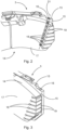
- Fig. 1 shows a partial illustration of a brake system 1 comprising a disc brake 2 and brake pads 3 and Fig. 1a illustrates an enlarged region of the brake system 1 of Fig. 1 .
- the disc brake 2 is connected to a collection device, in particular, a suction device, (not shown) for brake wear particles.
- the disc brake 2 further comprises a brake disc 4 and a non-rotatable component.
- the non-rotatable component comprises a brake carrier 5 and a brake caliper 6 configured to accommodate the brake pads 3.
- the brake carrier 5 carries the brake caliper 6, in particular, a guiding wire 12 is mounted on the brake carrier 5 and guides a connecting part 9.
- no separate brake carrier 5 is provided but the brake caliper 6 is directly attached to an axle of a vehicle.
- the brake caliper 6 comprises an actuator 7 configured to move the brake pads 3 in a direction toward the brake disc 4 for performing braking and a caliper releasing mechanism which is configured to move the brake pads 3 in a direction away from the brake disc 4 for automatically releasing the brake when the actuator 7 is deactivated.
- the caliper releasing mechanism comprises a pair of longitudinal spring elements 8, 8', the first end 8.1, 8'.1 of which is respectively joined to one of the brake pads 3 and second ends 8.2, 8'.2 of which are joined to one another by means of the connecting part 9 attached to the brake carrier 5 such that the caliper releasing mechanism is configured to be tensioned by a motion of the brake pads 3 in direction toward the brake disc 4. Therefore, the longitudinal spring elements 8, 8' are pretensioned and spread the brake pads 3 in order to avoid drag torque at the brake.
- the spring elements 8, 8' are not pretensioned and/or the second ends 8.2, 8'.2 are not joined to one another by means of the connecting part 9 but they are directly joined to one another and to the non-rotatable component.
- the longitudinal spring elements 8' on the right side of Fig. 1 and in Fig. 1a are respectively formed by a tube and the first ends 8'.1 of the tubes are respectively configured to collect brake wear particles and the second ends 8'.2 are connected to the collection device (not shown) such that the tubes are components of a brake wear removal equipment configured to collect brake wear particles and to be connectable to the collection device.
- the tubes do not form the longitudinal spring elements 8' but are provided additionally to the longitudinal spring elements 8'.
- the brake caliper 6 is provided with another component collecting bake wear particles and being connectable to a collection device, e.g. a channel made from a bent sheet metal.
- one of the caliper releasing devices on an outgoing side of the disc brake 2 has tubes being the longitudinal spring elements 8' and the other caliper releasing device has longitudinal spring elements 8 formed of wires.
- the outgoing side is this side where, when rotating in a direction of travel, the surface elements of the rotating disc brake leave the contact area of the disc brake and the brake pad.
- both caliper releasing devices are provided with tubes being the longitudinal spring elements 8'.
- the second ends 8'.2 are connected to the collection device via a pipe 10 connected to the second ends 8'.2 of the tubes via the connecting part 9 and via a flexible hose 11 joined to the pipe 10.
- the pipe 10 is designed to sustain high temperatures in this area and to avoid getting in contact with a turning rim of the brake disc 4.
- the hose 11 is designed flexible to compensate the axial displacement of the brake caliper 6 due to brake pad/brake disc wear and displacement while breaking.
- the pipe 10 and/or the hose 11 can be omitted if the component attached to the second ends 8'.2 is heat-resistant enough and has an appropriate flexibility.
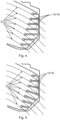
- Fig. 2 shows a partial illustration of a brake pad 3 according to a first embodiment in a first viewing direction
- Fig. 3 shows a partial illustration of the brake pad 3 according to the first embodiment in a second viewing direction.
- the brake pad 3 comprises a back plate 13 and a brake lining 14.
- the brake lining 14 is attached to the back plate 13 on an attachment face 15 of the back plate 13.
- the back plate 13 further comprises a blind hole 16 along the attachment face 15, i.e., parallel with respect to the attachment face 15.
- the blind hole 16 is formed as a bore.
- the blind hole 16 can also be formed as, e.g., a through hole with a plug, a recess in the attachment face 15 or as a recess or a bore which is not exactly parallel to the attachment face 15.
- the brake lining 14 has the shape like a segment of an annulus around a center.
- the center corresponds to a turning center of the rotatable brake disc 4.
- the brake lining 14 has another shape, e.g., a circular shape.
- the blind hole 16 is formed in a circumferential region of the back plate 13. This means that the blind hole 16 is formed close to an outside circumference of the back plate 13. In the present embodiment, the blind hole 16 is close to an end of the back plate 13 in the circumferential direction. In particular, the blind hole 16 is close to the end at the outgoing side of the brake pad 3. In alternative embodiments, several blind holds 16 are provided, in particular, on the outgoing side and on the ingoing side of the brake pad 3, i.e., in opposite circumferential regions of the back plate 13.
- the brake lining 14 comprises several channels 18 connecting the one blind hole 16 and a friction surface 17 of the brake lining 14. All of the channels 18 extend to the outside circumference of the brake lining 14 such that the channels 14 respectively form a slot 19 in the brake lining 14. For the sake of clarity, in this figure and in the subsequent figures, not all of the channels 18 and of the slots 19 are designated by a reference sign. In alternative embodiments, not all of the channels 14 but merely one or some of the channels 14 extend to the outside circumference of the brake lining 14 and respectively form one of the slots 19.
- the blind hole 16 has a central axis 21.
- the channels 18 extending to the outer circumference of the brake lining 14 are arranged such that, in a view onto the friction surface 17, a projection of each point of the central axis 21 onto the friction surface in a predefined area of the brake lining 14, which projection is virtually displaced perpendicularly with respect to the central axis 21 towards the outside circumference intersects with at least one of the slots 19. Therefore, when the brake pad 3 is oriented such that the central axis 21 of the blind hole 16 is in an almost radial direction in an installed state of the brake pad 3, a path 20 ( Figs. 4, 5 ) of each of the wear particles intersects one of the slots 19.
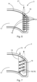
- Fig. 4 shows a partial illustration of the brake pad 3 according to the first embodiment in a third viewing direction and paths 20 of brake wear particles.
- the paths 20 are sections of circles around the center which correspond to the rotational axis of the brake disc 4. On these paths 20, particles adhered to the brake disc 4 move when the brake disc 4 rotates.
- Each of the path 20 intersect with at least one of the channels 18, in this embodiment, formed by the slots 19.
- the paths 20 are only exemplary paths since the particles are generated by the entire contact surface of the brake lining 14 and the brake disc 4. Therefore, in a predefined area of the brake lining 14, a projection, onto the friction surface 17, of each point of a line through the center virtually rotated around the center intersects with at least one of the channels 18.
- the predefined area is an area of the brake lining 14 where the wear particles are to be removed. Inner and outer areas in the radial direction of the brake lining 14 in the assembled state are not included in this predefined area since, when providing a channel in these inner and outer areas, there is the risk that the brake linings 14 break out in these areas.
- the slots 19 do not intersect in order not to create separated regions which could break away at the outer region of the brake lining 14.
- the slots 19 are parallel.
- Fig. 5 shows a partial illustration of the brake pad 3 according to a second embodiment and paths of wear particles.
- Fig. 5 distinguishes from the embodiment shown in Fig. 4 that the slots 19, formed by the channels 18, extending to the outer circumference of the brake lining 14, even though they also do not intersect, are not parallel. Nevertheless, all of the exemplary paths 20 of the wear particles also intersect these slots 19 formed by the channels 18.
- Fig. 6 shows a partial illustration of a brake pad 3 according to a third embodiment.
- the channels 18 are arranged such that the orifices of the channels 18 connecting the blind hole 16 and the friction surface 17 are aligned in one row.
- the orifices are formed by the channels 18 connecting several blind holes 16 and the friction surface 17 and the orifices of the channels 18 connected to one of the blind holes 16 are arranged in one row.
- the row is not aligned such that is directed to the rotational axis of the brake disc 4 but the disc brake 2 is configured such that the central axis 21 of the blind hole 16 of the brake pads 3 leads past a turning centre of the rotatable brake disc 4 such that a direction of the virtual displacement differs from a tangential direction of the brake disc. Nevertheless, the slots 19 also extend parallel to the outer circumference of the brake lining 14.
- the channels 18 are arranged such that the orifices of at least two blind holes 16 are provided.
- Fig. 7 shows a partial illustration of a brake pad 3 according to a fourth embodiment.
- the channels 18 of this embodiment distinguish from the channels 18 of the preceding embodiments in that the channels 18 do not extend to the outer circumference.
- two blind holes 16 are provided in the back plate 13 so that the orifices in the friction surface 17 are aligned in two rows.
- the two blind holds 16 of this embodiment are connected by the slots 19 formed by the channels 18.
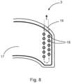
- Fig. 8 shows a partial illustration of a brake pad according to a fifth embodiment.
- the orifices of the channels 18 are arranged in two rows, nevertheless, the channels 18 connect only one blind hole 16 and the friction surface 17.
- the first ends 8'.1 ( Fig. 1 ) of the tubes are connected to the blind holes 16 of the brake pads 3 and the disc brake 2 is configured such that an open end of the blind hole 16 is arranged at an end face of the back plate 13 directed away from the turning center of the rotatable brake disc 4. Alternatively, the open end of the blind hole 16 is provided at another location of the back plate 13.
- the brake pads 3 are moved in the direction towards the brake disc 4 by the actuator 7.
- the actuator 7 is deactivated, the brake pads 3 are automatically moved in the direction away from the brake disc 4 by the caliper releasing mechanism.
- the brake wear particles are moved away from the brake pad via the channels 18 and the blind hole 16 of the brake pads 3.
Landscapes
- Engineering & Computer Science (AREA)
- General Engineering & Computer Science (AREA)
- Mechanical Engineering (AREA)
- Braking Arrangements (AREA)
Description
- The invention relates to a disc brake, a brake pad, and a brake system comprising the disc brake and the brake pad, in particular, collaborating with a brake particles collection system.
- Brake particles collection systems are known, e.g., from a publication made with Springer Verlag "At source brake dust collection system". According to this publication, suction grooves are machined at trailing edges of brake pads for collecting wear particles for giving the best results. At an "outlet flow", pipes connected to an electrical suction turbine and a filter are connected.
- Furthermore, documents
US 2021/123489 A1 ,US 2020/340541 A1 ,WO 2020/193776 A1 andWO 2020/193775 A1 describe different types of suction grooves. - To make an active local suction device for wear particles efficient, the particles have to be sucked off directly where they are generated, e.g., directly behind the brake pads or by means of grooves in the brake pads as mentioned before.
-
Document EP 3 470 700 A1 discloses a disc brake provided with a rotatable brake disc and a non-rotatable component comprising a brake caliper. The brake caliper comprises a brake wear removal equipment configured to collect brake wear particles and to be connectable to a collection device, wherein the brake wear removal equipment comprises at least one tube, a first end of which is configured to collect brake wear particles and a second end of which is connectable to the collection device. - In
JP 2009236221 A - However, due to the rotating disc and the limited installation space in commercial vehicles, it is difficult to collect the wear particles at both brake pads, namely, on both sides of the disc. Flexible hoses could be used for a particle transport since they are able to compensate a displacement of brake pads and of a brake caliper; however, again, only limited space is available and, furthermore, the temperature in the environment at the disc can be very high such that the use of flexible hoses is limited. As another option, suction channels inside the brake caliper or brake carrier would be possible; however, they are expensive and could clog over the brake lifetime. Furthermore, such channels would weaken the components of the brake or, when the weakening is compensated, would increase the weight and installation space demand of the components.
- The object underlying the invention is to remedy the above disadvantages and to provide a brake system enabling a reliable removal of wear particles of brake pads while maintaining advantageous characteristics of the brake system.
- The object is achieved by a disc brake according to
claim 1, a brake pad according toclaim 6 and brake systems according toclaims - According to the invention, a disc brake is provided with a rotatable brake disc and a non-rotatable component comprising a brake caliper. The brake caliper comprises a brake wear removal equipment configured to collect brake wear particles and to be connectable to a collection device.
- Due to such a disc brake, no additional brackets for the brake wear removal equipment are necessary and the brake wear can be removed directly at the location where it is generated.
- According to the invention, the brake wear removal equipment comprises at least one tube, a first end of which is configured to collect brake wear particles and a second end of which is connectable to the collection device.
- By the provision of the tube as the brake wear removal equipment on the brake caliper, the brake wear particles can be remove in an easy and reliable manner. Further, the components can easily be designed such that they resist a high thermal load.
- According to the invention, the brake caliper is configured to accommodate brake pads, and the brake caliper comprises an actuator configured to move the brake pads in a direction toward the brake disc for performing braking, and at least one caliper releasing mechanism configured to move the brake pads in a direction away from the brake disc for releasing the braking when the actuator is deactivated. The at least one caliper releasing mechanism comprises a pair of longitudinal spring elements, a first end of which is respectively joined to one of the brake pads and second ends of which are joined to one another and to the non-rotatable component such that the at least one caliper releasing mechanism is configured to be tensioned by a motion of the brake pads in the direction toward the brake disc. The longitudinal spring elements are respectively formed by a tube, and the first ends of the tubes are respectively configured to collect brake wear particles and the second ends are connectable to the collection device.
- By such a disc brake, the brake wear particles can be removed without requiring additional installation space and without additional components compared to the conventional brake particle collection systems. Furthermore, the tubes being the spring elements for an active caliper release system can be easily exchanged when replacing the brake pads so that the clog over the lifetime of the brakes is avoided. Finally, also avoidance of drag torque is possible without using additional components.
- In an advantageous implementation of the disc brake, the non-rotatable component comprises a brake carrier carrying the brake caliper, and the second ends of the tubes are joined to one another by means of a connecting part attached to the brake carrier.
- Due to the use of the connecting part attached to the brake carrier for joining the second ends of the tubes, the tubes collecting the brake wear particles are able to reliably function as the caliper releasing mechanism.
- In a further advantageous implementation of the disc brake, the second ends are connected to the collection device via a pipe connected to the second ends of the tubes.
- By using the pipe, a material with higher thermal durability resisting high temperatures can be used so that, contrary to the use of a material, used, e.g., for hoses, which cannot resist higher temperatures, problems caused by the high temperatures during lifetime of the pipe can be avoided.
- In a further advantageous implementation of the disc brake, the second ends are connected to the collection device via a flexible hose.
- When using the flexible hose, compensation of the displacement of the caliper by each brake actuation and over the pad lifetime is possible. The flexible hose can be connected either to the second end of the tubes lead away from the region with the high temperatures or to the pipe.
- Due to a further advantageous implementation of the disc brake, the brake caliper comprises two caliper releasing mechanisms having the tubes being the longitudinal spring elements.
- When using the two caliper releasing mechanisms having the tubes, in case that the brake pads are accordingly prepared, removal of the brake wear particles at two places of the brake pads is possible which enhances the result of the removal.
- According to a further aspect of the invention, a brake pad for a disc brake is provided. The brake pad comprises a back plate and a brake lining, wherein the brake lining is attached to the back plate on an attachment face of the back plate. The back plate comprises at least one blind hole along the attachment face, and the brake lining comprises several channels connecting one blind hole and a friction surface of the brake lining.
- When connecting one blind hole and the friction surface of the brake lining by several channels, the places where the brake wear particles can removed can be distributed across the friction surface so that the effect of removing the brake wear particles is improved and a risk that the removal is deteriorated is reduced since, even when one of the channels is clogged, the remaining channels can further remove the particles.
- In an advantageous implementation of the brake pad, the at least one blind hole is formed in a circumferential region of the back plate.
- Arranging the blind hole in a circumferential region enables the orientation of the brake pad such that the blind hole, and, therefore, the channels connecting the blind hole and the friction surface of the brake lining can be located at the outgoing side of the brake. The outgoing side is this side where, when rotating in a direction of travel, the surface elements of the rotating disc brake leave the contact area of the disc brake and the brake pad. Therefore, the wear particles of the brake lining which are worn on the entire contact area during a braking action are moved to the outgoing side and, therefore, to the channels.
- In an advantageous implementation of the brake pad, several blind holes are formed in opposite circumferential regions of the back plate.
- By this implementation, as mentioned above, the wear particles currently worn from the brake lining can be removed and, also, wear particles which remained on the surface of the disc brake or which are generated when the brake disc rotates opposite to the direction of travel, can be removed.
- In a further advantageous implementation of the brake pad, the channels are arranged such that orifices in the friction surface formed by the channels are aligned in at least one row.
- When the orifices are aligned in one row, in particular, when the row corresponds to the direction of the blind hole, the channels can be designed short and the risk of clogging is reduced.
- Due to a further advantageous implementation of a brake pad, the orifices are aligned in two rows, and the channels of one row are connected to one blind hole.
- By this arrangement, the orifices can be arranged that, in a predefined area of the brake lining, the orifices can cover the entire predefined area of the brake lining in one direction since the can overlap. Therefore, all of the wear particles moving perpendicular to direction of the aligned orifices, can be removed.
- According to the invention, at least some of the channels extend to an outside circumference of the brake lining such that the channels respectively form a slot in the brake lining.
- Due to the fact that at least some of the channels extend to an outside circumference of the brake lining, when selecting an appropriate angle between the slot and the moving direction of the wear particles, the wear particles can be removed easily since through an orifice formed at an end face of the brake lining by the slots, air can be sucked into the slot and, therefore, into the channels and the blind hole for removing the wear particles.
- Due to a further advantageous implementation of the brake pad, all of the channels extend to the outside circumference of the brake lining.
- In this implementation, the effect of the preceding implementation can be improved.
- In a further advantageous implementation of the brake pad, the slots do not intersect, in particular, the slots are parallel.
- When the slots extending to the outside circumference of the brake lining do not intersect, so-called peninsulas between the slots are formed. These peninsulas are connected to regions of the brake lining in a motion direction of the brake disc before the channels. Therefore, a separated region which has been formed in the state-of-the-art between a slot and the outside circumference by providing the slot in the brake lining can be avoided'. This avoids the disadvantage of the risk that the brake lining could be damaged and the braking effect would be deteriorated as caused in the state of the art by a region separated from the remaining area of the brake lining.
- In a further advantageous implementation of the brake pad, the blind hole has a central axis, and the channels extending to the outside circumference are arranged such that, in a view onto the friction surface, a projection of each point of the central axis onto the friction surface in a predefined area of the brake lining, which projection is virtually displaced perpendicularly with respect to the central axis towards the outside circumference intersects with at least one of the slots.
- When the brake pad is oriented such that the blind hole and, therefore, its central axis are in an almost radial direction of the brake disk, since the central axis of the blind hole crosses the predefined area, the wear particles on the entire friction surface in the predefined area can be removed since the wear particles following the rotational motion of the disc brake fall into one of the channels extending to the outer circumference perpendicular with respect to the central axis.
- In a further advantageous implementation of the brake pad, the brake lining has a shape like a segment of an annulus around a centre, and the channels are arranged such that, in a view onto the friction surface, in a predefined area of the brake lining, a projection onto the friction surface of each point of a line through the centre virtually rotated around the centre intersects with at least one of the channels.
- Due to this implementation, wherein the shape is the shape of usually provided brake pads, namely, being a segment of an annulus around a centre, wherein the centre is the rotational axis of the brake disc, the wear particles following the rotational motion of the disc brake fall into one of the channels which intersect with each point of a line through the centre virtually rotated about the centre.
- According to a further aspect of the invention, a brake system comprises a disc brake connected to a collection device for wear particles, wherein the first ends of the tubes are respectively configured to collect brake wear particles and the second ends are connected to a collection device, and brake pads.
- By such a brake system, the wear particles can be removed without requiring additional installation space and without additional components compared to the conventional brake particle collection systems. Furthermore, the components can easily be designed such that they resist a high thermal load. Moreover, the tubes being the spring elements for the active caliper release system can be easily exchanged when replacing the brake pads so that the clog over the lifetime of the brakes is avoided. Finally, also avoidance of drag torque is possible without using additional components.
- According to a further aspect of the invention, a brake system comprises a disc brake connected to a collection device for brake wear particles and brake pads comprising several channels connecting one blind hole in a back plate of the brake pad and a friction surface of the brake lining.
- By providing the disc brake connected to the collection device, when connecting the blind hole and the friction surface of the brake lining by several channels, the places where the brake wear particles can removed can be distributed across the friction surface so that the effect of removing the brake wear particles is improved and a risk that the removal is deteriorated is reduced since, even when one of the channels is clogged, the remaining channels can further remove the particles.
- According to an advantageous implementation of the brake system, the disc brake comprises a disc brake having the caliper releasing mechanism, as longitudinal spring elements, including tubes, the first ends of which are respectively configured to collect brake wear particles and the second ends are connected to the collection device.
- By such a brake system, the wear particles can be removed without requiring additional installation space and without additional components compared to the conventional brake particle collection systems. Furthermore, the components can easily be designed such that they resist a high thermal load. Moreover, the tubes being the spring elements for the active caliper release system can be easily exchanged when replacing the brake pads so that the clog over the lifetime of the brakes is avoided. Finally, also avoidance of drag torque is possible without using additional components.
- In an advantageous implementation of the brake system, the first end of the tubes are connected to the blind hole.
- This implementation provides the most advantages effect of removing the wear particles.
- In a further advantageous implementation of the brake system, the disc brake is configured such that an open end of the blind hole is arranged at an end face of the back plate directed away from a turning centre of the rotatable brake disc.
- When the open end of the blind hole is directed away from the turning center of the rotatable brake disc, this arrangement enables short lines for removing the wear particles and enables an advantageous service since the lines are easily assessable.
- In yet a further advantageous implementation of the brake system, the disc brake is configured such that the central axis of the blind hole of the brake pads leads beyond a turning centre of the rotatable brake disc such that a direction of a virtual displacement of the projection of each point of the central axis differs from a tangential direction of the brake disc.
- By this arrangement, the function of the removal of the wear particles is insured when the channels extending to the outside circumference are arranged such that, in the view onto the friction surface, the projection of each point of the central axis onto the friction surface in a predefined area of the brake lining, which projection is virtually displaced perpendicularly with respect to the central axis towards the outside circumference along the slots intersects with at least one of the slots.
- Below, the invention is elucidated by means of embodiments referring to the attached drawings.
- In particular,
- Fig. 1
- shows a partial illustration of a brake system comprising a disc brake and brake pads;
- Fig. 1a
- shows an enlarged region of the brake system of
Fig. 1 ; - Fig. 2
- shows a partial illustration of a brake pad according to a first embodiment in a first viewing direction;
- Fig. 3
- shows a partial illustration of the brake pad according to the first embodiment in a second viewing direction;
- Fig. 4
- shows a partial illustration of the brake pad according to the first embodiment in a third viewing direction and paths of break wear particles;
- Fig. 5
- shows a partial illustration of the brake pad according to a second embodiment and paths of break wear particles;
- Fig. 6
- shows a partial illustration of a brake pad according to a third embodiment;
- Fig. 7
- shows a partial illustration of a brake pad according to a fourth embodiment; and
- Fig. 8
- shows a partial illustration of a brake pad according to a fifth embodiment.
-
Fig. 1 shows a partial illustration of abrake system 1 comprising adisc brake 2 andbrake pads 3 andFig. 1a illustrates an enlarged region of thebrake system 1 ofFig. 1 . Thedisc brake 2 is connected to a collection device, in particular, a suction device, (not shown) for brake wear particles. Thedisc brake 2 further comprises abrake disc 4 and a non-rotatable component. - The non-rotatable component comprises a
brake carrier 5 and abrake caliper 6 configured to accommodate thebrake pads 3. Thebrake carrier 5 carries thebrake caliper 6, in particular, a guidingwire 12 is mounted on thebrake carrier 5 and guides a connectingpart 9. In an alternative embodiment, noseparate brake carrier 5 is provided but thebrake caliper 6 is directly attached to an axle of a vehicle. - The
brake caliper 6 comprises anactuator 7 configured to move thebrake pads 3 in a direction toward thebrake disc 4 for performing braking and a caliper releasing mechanism which is configured to move thebrake pads 3 in a direction away from thebrake disc 4 for automatically releasing the brake when theactuator 7 is deactivated. - The caliper releasing mechanism comprises a pair of
longitudinal spring elements 8, 8', the first end 8.1, 8'.1 of which is respectively joined to one of thebrake pads 3 and second ends 8.2, 8'.2 of which are joined to one another by means of the connectingpart 9 attached to thebrake carrier 5 such that the caliper releasing mechanism is configured to be tensioned by a motion of thebrake pads 3 in direction toward thebrake disc 4. Therefore, thelongitudinal spring elements 8, 8' are pretensioned and spread thebrake pads 3 in order to avoid drag torque at the brake. In alternative embodiments, thespring elements 8, 8' are not pretensioned and/or the second ends 8.2, 8'.2 are not joined to one another by means of the connectingpart 9 but they are directly joined to one another and to the non-rotatable component. The longitudinal spring elements 8' on the right side ofFig. 1 and inFig. 1a are respectively formed by a tube and thefirst ends 8'.1 of the tubes are respectively configured to collect brake wear particles and thesecond ends 8'.2 are connected to the collection device (not shown) such that the tubes are components of a brake wear removal equipment configured to collect brake wear particles and to be connectable to the collection device. In alternative embodiments, the tubes do not form the longitudinal spring elements 8' but are provided additionally to the longitudinal spring elements 8'. In a further additional embodiment, thebrake caliper 6 is provided with another component collecting bake wear particles and being connectable to a collection device, e.g. a channel made from a bent sheet metal. - As shown in
Fig. 1 , one of the caliper releasing devices on an outgoing side of thedisc brake 2 has tubes being the longitudinal spring elements 8' and the other caliper releasing device haslongitudinal spring elements 8 formed of wires. The outgoing side is this side where, when rotating in a direction of travel, the surface elements of the rotating disc brake leave the contact area of the disc brake and the brake pad. In alternative embodiments, both caliper releasing devices are provided with tubes being the longitudinal spring elements 8'. - As to be seen in
Fig. 1a , thesecond ends 8'.2 are connected to the collection device via apipe 10 connected to thesecond ends 8'.2 of the tubes via the connectingpart 9 and via aflexible hose 11 joined to thepipe 10. Thepipe 10 is designed to sustain high temperatures in this area and to avoid getting in contact with a turning rim of thebrake disc 4. Thehose 11 is designed flexible to compensate the axial displacement of thebrake caliper 6 due to brake pad/brake disc wear and displacement while breaking. In alternative embodiments, thepipe 10 and/or thehose 11 can be omitted if the component attached to thesecond ends 8'.2 is heat-resistant enough and has an appropriate flexibility. -
Fig. 2 shows a partial illustration of abrake pad 3 according to a first embodiment in a first viewing direction andFig. 3 shows a partial illustration of thebrake pad 3 according to the first embodiment in a second viewing direction. - The
brake pad 3 comprises aback plate 13 and abrake lining 14. Thebrake lining 14 is attached to theback plate 13 on anattachment face 15 of theback plate 13. Theback plate 13 further comprises ablind hole 16 along theattachment face 15, i.e., parallel with respect to theattachment face 15. In this embodiment, theblind hole 16 is formed as a bore. In alternative embodiments, theblind hole 16 can also be formed as, e.g., a through hole with a plug, a recess in theattachment face 15 or as a recess or a bore which is not exactly parallel to theattachment face 15. - In the shown embodiment, the
brake lining 14 has the shape like a segment of an annulus around a center. The center corresponds to a turning center of therotatable brake disc 4. In alternative embodiments, thebrake lining 14 has another shape, e.g., a circular shape. - The
blind hole 16 is formed in a circumferential region of theback plate 13. This means that theblind hole 16 is formed close to an outside circumference of theback plate 13. In the present embodiment, theblind hole 16 is close to an end of theback plate 13 in the circumferential direction. In particular, theblind hole 16 is close to the end at the outgoing side of thebrake pad 3. In alternative embodiments, several blind holds 16 are provided, in particular, on the outgoing side and on the ingoing side of thebrake pad 3, i.e., in opposite circumferential regions of theback plate 13. - The
brake lining 14 comprisesseveral channels 18 connecting the oneblind hole 16 and afriction surface 17 of thebrake lining 14. All of thechannels 18 extend to the outside circumference of thebrake lining 14 such that thechannels 14 respectively form aslot 19 in thebrake lining 14. For the sake of clarity, in this figure and in the subsequent figures, not all of thechannels 18 and of theslots 19 are designated by a reference sign. In alternative embodiments, not all of thechannels 14 but merely one or some of thechannels 14 extend to the outside circumference of thebrake lining 14 and respectively form one of theslots 19. - The
blind hole 16 has acentral axis 21. Thechannels 18 extending to the outer circumference of thebrake lining 14 are arranged such that, in a view onto thefriction surface 17, a projection of each point of thecentral axis 21 onto the friction surface in a predefined area of thebrake lining 14, which projection is virtually displaced perpendicularly with respect to thecentral axis 21 towards the outside circumference intersects with at least one of theslots 19. Therefore, when thebrake pad 3 is oriented such that thecentral axis 21 of theblind hole 16 is in an almost radial direction in an installed state of thebrake pad 3, a path 20 (Figs. 4, 5 ) of each of the wear particles intersects one of theslots 19. -
Fig. 4 shows a partial illustration of thebrake pad 3 according to the first embodiment in a third viewing direction andpaths 20 of brake wear particles. Thepaths 20 are sections of circles around the center which correspond to the rotational axis of thebrake disc 4. On thesepaths 20, particles adhered to thebrake disc 4 move when thebrake disc 4 rotates. Each of thepath 20 intersect with at least one of thechannels 18, in this embodiment, formed by theslots 19. Thepaths 20 are only exemplary paths since the particles are generated by the entire contact surface of thebrake lining 14 and thebrake disc 4. Therefore, in a predefined area of thebrake lining 14, a projection, onto thefriction surface 17, of each point of a line through the center virtually rotated around the center intersects with at least one of thechannels 18. The predefined area is an area of thebrake lining 14 where the wear particles are to be removed. Inner and outer areas in the radial direction of thebrake lining 14 in the assembled state are not included in this predefined area since, when providing a channel in these inner and outer areas, there is the risk that thebrake linings 14 break out in these areas. - As shown in
Fig. 4 , theslots 19 do not intersect in order not to create separated regions which could break away at the outer region of thebrake lining 14. In particular, in the embodiment shown inFig. 4 , theslots 19 are parallel. -
Fig. 5 shows a partial illustration of thebrake pad 3 according to a second embodiment and paths of wear particles. - The embodiment according to
Fig. 5 distinguishes from the embodiment shown inFig. 4 that theslots 19, formed by thechannels 18, extending to the outer circumference of thebrake lining 14, even though they also do not intersect, are not parallel. Nevertheless, all of theexemplary paths 20 of the wear particles also intersect theseslots 19 formed by thechannels 18. -
Fig. 6 shows a partial illustration of abrake pad 3 according to a third embodiment. As already shown in the preceding embodiments, thechannels 18 are arranged such that the orifices of thechannels 18 connecting theblind hole 16 and thefriction surface 17 are aligned in one row. In an alternative embodiment, the orifices are formed by thechannels 18 connecting severalblind holes 16 and thefriction surface 17 and the orifices of thechannels 18 connected to one of theblind holes 16 are arranged in one row. Contrary to the first and second embodiment, the row is not aligned such that is directed to the rotational axis of thebrake disc 4 but thedisc brake 2 is configured such that thecentral axis 21 of theblind hole 16 of thebrake pads 3 leads past a turning centre of therotatable brake disc 4 such that a direction of the virtual displacement differs from a tangential direction of the brake disc. Nevertheless, theslots 19 also extend parallel to the outer circumference of thebrake lining 14. - In an alternative embodiment, the
channels 18 are arranged such that the orifices of at least twoblind holes 16 are provided. -
Fig. 7 shows a partial illustration of abrake pad 3 according to a fourth embodiment. - The
channels 18 of this embodiment distinguish from thechannels 18 of the preceding embodiments in that thechannels 18 do not extend to the outer circumference. In this embodiment, twoblind holes 16 are provided in theback plate 13 so that the orifices in thefriction surface 17 are aligned in two rows. The two blind holds 16 of this embodiment are connected by theslots 19 formed by thechannels 18. -
Fig. 8 shows a partial illustration of a brake pad according to a fifth embodiment. - In this fifth embodiment, the orifices of the
channels 18 are arranged in two rows, nevertheless, thechannels 18 connect only oneblind hole 16 and thefriction surface 17. - The first ends 8'.1 (
Fig. 1 ) of the tubes are connected to theblind holes 16 of thebrake pads 3 and thedisc brake 2 is configured such that an open end of theblind hole 16 is arranged at an end face of theback plate 13 directed away from the turning center of therotatable brake disc 4. Alternatively, the open end of theblind hole 16 is provided at another location of theback plate 13. - In use, for performing braking, the
brake pads 3 are moved in the direction towards thebrake disc 4 by theactuator 7. When, after the braking request, theactuator 7 is deactivated, thebrake pads 3 are automatically moved in the direction away from thebrake disc 4 by the caliper releasing mechanism. - Simultaneously, when the
disc brake 2 is connected to the collection device and the collection device operates, the brake wear particles are moved away from the brake pad via thechannels 18 and theblind hole 16 of thebrake pads 3. - Although the present invention has been described with reference to specific features and embodiments thereof, it is evident that various modifications and combinations can be made thereto without departing from the spirit and scope of the invention. The specification and drawings are, accordingly, to be regarded simply as an illustration of the invention as defined by the appended claims, and are contemplated to cover any and all modifications, variations combinations or equivalents that fall within the scope of the present invention.
-
- 1
- brake system
- 2
- disc brake
- 3
- brake pad
- 4
- brake disc
- 5
- brake carrier
- 6
- brake caliper
- 7
- actuator
- 8, 8'
- spring elements
- 8'.1
- first end of tube
- 8'.2
- second end of tube
- 9
- connecting part
- 10
- pipe
- 11
- hose
- 12
- guiding wire
- 13
- back plate
- 14
- brake lining
- 15
- attachment face
- 16
- blind hole
- 17
- friction surface
- 18
- channel
- 19
- slot
- 20
- path of a ware particular
- 21
- central axis
Claims (20)
- A disc brake (2) provided with a rotatable brake disc (4) and a non-rotatable component comprising a brake caliper (6), whereinthe brake caliper (6) comprises a brake wear removal equipment configured to collect brake wear particles and to be connectable to a collection device,the brake wear removal equipment comprises at least one tube, a first end of which is configured to collect brake wear particles and a second end of which is connectable to the collection device, andthe brake caliper (6) is configured to accommodate brake pads (3), andthe brake caliper (6) comprisesan actuator (7) configured to move the brake pads (3) in a direction toward the brake disc (4) for performing braking, andat least one caliper releasing mechanism configured to move the brake pads (3) in a direction away from the brake disc (4) for releasing the braking, whereinthe at least one caliper releasing mechanism comprises a pair of longitudinal spring elements (8, 8'), a first end (8.1, 8'.1) of which is respectively joined to one of the brake pads (3) and second ends (8.2, 8'.2) of which are joined to one another and to the non-rotatable component such that the at least one caliper releasing mechanism is configured to be tensioned by a motion of the brake pads (3) in the direction toward the brake disc (4),characterized in thatthe longitudinal spring elements (8 ') are respectively formed by one of the at least one tube, andthe first ends (8'.1) of the tubes are respectively configured to collect brake wear particles and the second ends (8'.2) are connectable to the collection device.
- The disc brake (2) of claim 1, whereinthe non-rotatable component comprises a brake carrier (5) carrying the brake caliper (6), andthe second ends (8'.2) of the tubes are joined to one another by means of a connecting part (9) attached to the brake carrier (5).
- The disc brake (2) of claims 1 or 2, wherein
the second ends (8'.2) are connected to the collection device via a pipe (10) connected to the second ends (8'.2) of the tubes. - The disc brake (2) of claim 2 or 3, wherein
the second ends (8'.2) are connected to the collection device via a flexible hose (11). - The disc brake (2) of anyone of the preceding claims, wherein
the brake caliper (6) comprises two caliper releasing mechanisms having the tubes being the longitudinal spring elements (8). - A brake pad (3) for a disc brake (2), the brake pad (3) comprisinga back plate (13) and a brake lining (14), whereinthe brake lining (14) is attached to the back plate (13) on an attachment face (15) of the back plate (13),the back plate (13) comprises at least one blind hole (16) along the attachment face (15), andthe brake lining (14) comprises several channels (18) connecting one blind hole (16) and a friction surface (17) of the brake lining (14),characterized in thatat least some of the channels (18) extend to an outside circumference of the brake lining (14) such that the channels (18) respectively form a slot (19) in the brake lining (14).
- The brake pad (3) of claim 6, wherein
the at least one blind hole (16) is formed in a circumferential region of the back plate (13). - The brake pad (3) of claim 7, wherein
several blind holes (16) are formed in opposite circumferential regions of the back plate (13). - The brake pad (3) of anyone of claims 6 to 8, wherein
the channels (18) are arranged such that orifices in the friction surface (17) formed by the channels (18) are aligned in at least one row. - The brake pad (3) of claim 9, whereinthe orifices are aligned in two rows, andthe channels (18) of one row are connected to one blind hole.
- The brake pad (3) of anyone of claims 6 to 10, wherein
all of the channels (18) extend to the outside circumference of the brake lining (14). - The brake pad (3) of anyone of claims 6 to 11, wherein
the slots (19) do not intersect, in particular, the slots (19) are parallel. - The brake pad (3) of anyone of claims 10 to 12, whereinthe blind hole (16) has a central axis (21), andthe channels (18) extending to the outside circumference are arranged such that, in a view onto the friction surface (17), a projection of each point of the central axis (21) onto the friction surface (17) in a predefined area of the brake lining (14), which projection is virtually displaced perpendicularly with respect to the central axis (21) towards the outside circumference, intersects with at least one of the slots (19).
- The brake pad (3) of anyone of claims 6 to 12 whereinthe brake lining (14) has a shape like a segment of an annulus around a centre, andthe channels (18) are arranged such that, in a view onto the friction surface (17), in a predefined area of the brake lining (14), a projection onto the friction surface (17) of each point of a line through the centre virtually rotated around the centre intersects with at least one of the channels (18).
- A brake system (1) comprising a disc brake (2), connected to a collection device for wear particles, and brake pads (3),
characterized in that
the disc brake (2) is a disc brake (2) according to anyone of claims 1 to 5. - A brake system (1) comprising a disc brake (2) connected to a collection device for brake wear particles,
characterized in that
the brake system (1) comprises brake pads (3) according to anyone of claims 6 to 14. - The brake system (1) of claim 16, wherein the disc brake (2) comprises a disc brake (2) according to anyone of claims 1 to 5.
- The brake system (1) of claim 17, wherein the first end (8'.1) of the tubes are connected to the blind hole (16).
- The brake system (1) of anyone of claims 16 to 18, wherein
the disc brake (2) is configured such that an open end of the blind hole (16) is arranged at an end face of the back plate (13) directed away from a turning centre of the rotatable brake disc (2). - The brake system (1) of anyone of claims 16 to 18 comprising a brake pad (3) according to claim 13, wherein
the disc brake (2) is configured such that the central axis (21) of the blind hole (16) of the brake pads (3) leads beyond a turning centre of the rotatable brake disc (2) such that a direction of a virtual displacement of the projection of each point of the central axis (21) differs from a tangential direction of the brake disc.
Priority Applications (1)
| Application Number | Priority Date | Filing Date | Title |
|---|---|---|---|
| EP21204888.8A EP4174339B1 (en) | 2021-10-27 | 2021-10-27 | Disc brake, brake pad and brake system comprising the disc brake and brake pads |
Applications Claiming Priority (1)
| Application Number | Priority Date | Filing Date | Title |
|---|---|---|---|
| EP21204888.8A EP4174339B1 (en) | 2021-10-27 | 2021-10-27 | Disc brake, brake pad and brake system comprising the disc brake and brake pads |
Publications (2)
| Publication Number | Publication Date |
|---|---|
| EP4174339A1 EP4174339A1 (en) | 2023-05-03 |
| EP4174339B1 true EP4174339B1 (en) | 2024-08-28 |
Family
ID=78413736
Family Applications (1)
| Application Number | Title | Priority Date | Filing Date |
|---|---|---|---|
| EP21204888.8A Active EP4174339B1 (en) | 2021-10-27 | 2021-10-27 | Disc brake, brake pad and brake system comprising the disc brake and brake pads |
Country Status (1)
| Country | Link |
|---|---|
| EP (1) | EP4174339B1 (en) |
Families Citing this family (3)
| Publication number | Priority date | Publication date | Assignee | Title |
|---|---|---|---|---|
| FR3154156A1 (en) * | 2023-10-17 | 2025-04-18 | Tallano Technologies | BRAKE PAD |
| FR3156176A1 (en) * | 2023-11-30 | 2025-06-06 | Tallano Technologies | BRAKE ASSEMBLY FOR A DISC BRAKE |
| FR3158344A1 (en) * | 2024-01-15 | 2025-07-18 | Tallano Technologies | Braking system |
Citations (4)
| Publication number | Priority date | Publication date | Assignee | Title |
|---|---|---|---|---|
| JP2005036829A (en) | 2003-07-15 | 2005-02-10 | Mitsubishi Electric Corp | Friction brake device |
| JP2013144585A (en) | 2012-01-13 | 2013-07-25 | Mitsubishi Electric Corp | Disk brake device for elevator winding machine, and powder dust removing method |
| EP3369959A1 (en) | 2015-10-30 | 2018-09-05 | Akebono Brake Industry Co., Ltd. | Disc-brake device |
| EP3470700A1 (en) | 2016-06-10 | 2019-04-17 | Akebono Brake Industry Co., Ltd. | Disc brake device |
Family Cites Families (10)
| Publication number | Priority date | Publication date | Assignee | Title |
|---|---|---|---|---|
| JP2009236221A (en) * | 2008-03-27 | 2009-10-15 | Advics Co Ltd | Disc brake device for vehicle |
| GB2492858C2 (en) * | 2011-12-06 | 2014-12-10 | Trevor Michael Mennie | Brake system |
| DE102016104967A1 (en) * | 2015-10-09 | 2017-04-13 | Knorr-Bremse Systeme für Nutzfahrzeuge GmbH | brake carrier |
| FR3069832B1 (en) * | 2017-08-01 | 2019-09-06 | Tallano Technologie | FRICTION ASSEMBLY FOR RAIL BRAKING SYSTEM |
| FR3071573B1 (en) * | 2017-09-26 | 2019-09-27 | Psa Automobiles Sa | BRAKE PAD WITH DUST COLLECTOR |
| FR3076876B1 (en) | 2018-01-17 | 2020-01-03 | Tallano Technologie | BRAKE PAD FOR DISC BRAKE ASSEMBLY COMPRISING A SUCTION GROOVE IN THE FRONT AREA AND A FRONT ZONE MOLDED |
| FR3076877B1 (en) | 2018-01-17 | 2020-01-03 | Tallano Technologie | DISC BRAKE PAD COMPRISING A COLLECTION GROOVE EXTENDING IN CONNECTION |
| DE102018120512B4 (en) * | 2018-08-22 | 2025-02-13 | Knorr-Bremse Systeme für Nutzfahrzeuge GmbH | Disc brake for a commercial vehicle and brake pad set |
| FR3094429B1 (en) | 2019-03-28 | 2021-04-16 | Tallano Tech | Braking system with centrifugal suction in the lining groove |
| FR3094428B1 (en) | 2019-03-28 | 2021-04-16 | Tallano Tech | Braking system with blowing in the lining groove |
-
2021
- 2021-10-27 EP EP21204888.8A patent/EP4174339B1/en active Active
Patent Citations (4)
| Publication number | Priority date | Publication date | Assignee | Title |
|---|---|---|---|---|
| JP2005036829A (en) | 2003-07-15 | 2005-02-10 | Mitsubishi Electric Corp | Friction brake device |
| JP2013144585A (en) | 2012-01-13 | 2013-07-25 | Mitsubishi Electric Corp | Disk brake device for elevator winding machine, and powder dust removing method |
| EP3369959A1 (en) | 2015-10-30 | 2018-09-05 | Akebono Brake Industry Co., Ltd. | Disc-brake device |
| EP3470700A1 (en) | 2016-06-10 | 2019-04-17 | Akebono Brake Industry Co., Ltd. | Disc brake device |
Also Published As
| Publication number | Publication date |
|---|---|
| EP4174339A1 (en) | 2023-05-03 |
Similar Documents
| Publication | Publication Date | Title |
|---|---|---|
| EP4174339B1 (en) | Disc brake, brake pad and brake system comprising the disc brake and brake pads | |
| JP6953522B2 (en) | Brake pads and brake units for capturing dust | |
| JP7424655B2 (en) | Brake pads with particulate and dust collection | |
| EP1610025B1 (en) | Method of operating a disc brake assembly | |
| US20230287945A1 (en) | Brake dust particle filter, disc brake assembly and method for collecting brake dust particles | |
| WO2017073574A1 (en) | Disc-brake device | |
| JP7475070B2 (en) | Brake system with centrifugal suction in the grooves of the lining | |
| US20230272828A1 (en) | Disk brake device and brake pad | |
| JP2018533706A5 (en) | ||
| JP2006501413A (en) | Disc brake with pressing member | |
| US20240159281A1 (en) | Disc brake and carrier | |
| US11346411B2 (en) | Braking device for vehicle | |
| CN114466982A (en) | Brake disc unit for railway vehicle | |
| RU2317454C2 (en) | Protecting cover for disk brake and disk brake | |
| CN114576290B (en) | Brake assembly guards and scrapers | |
| JP2017082969A (en) | Pad for disc brake and disc brake device | |
| US9062725B2 (en) | Brake assembly | |
| CA3050993C (en) | Brake shoe, system for modular assembly of a brake shoe, brake apparatus and method for producing a brake shoe | |
| KR20240171992A (en) | brake apparutus | |
| JP2023123867A (en) | Brake lining for railway vehicles | |
| CN113631458B (en) | Brake friction linings for railway vehicles | |
| US10047809B2 (en) | Drum brake dust shield for a vehicle braking system | |
| US20250383000A1 (en) | Brake pads | |
| CA3038425C (en) | Brake pad and braking unit for capturing particles |
Legal Events
| Date | Code | Title | Description |
|---|---|---|---|
| PUAI | Public reference made under article 153(3) epc to a published international application that has entered the european phase |
Free format text: ORIGINAL CODE: 0009012 |
|
| STAA | Information on the status of an ep patent application or granted ep patent |
Free format text: STATUS: THE APPLICATION HAS BEEN PUBLISHED |
|
| AK | Designated contracting states |
Kind code of ref document: A1 Designated state(s): AL AT BE BG CH CY CZ DE DK EE ES FI FR GB GR HR HU IE IS IT LI LT LU LV MC MK MT NL NO PL PT RO RS SE SI SK SM TR |
|
| STAA | Information on the status of an ep patent application or granted ep patent |
Free format text: STATUS: REQUEST FOR EXAMINATION WAS MADE |
|
| 17P | Request for examination filed |
Effective date: 20231103 |
|
| RBV | Designated contracting states (corrected) |
Designated state(s): AL AT BE BG CH CY CZ DE DK EE ES FI FR GB GR HR HU IE IS IT LI LT LU LV MC MK MT NL NO PL PT RO RS SE SI SK SM TR |
|
| RAP3 | Party data changed (applicant data changed or rights of an application transferred) |
Owner name: KNORR-BREMSE SYSTEME FUER NUTZFAHRZEUGE GMBH |
|
| RIC1 | Information provided on ipc code assigned before grant |
Ipc: F16D 65/092 20060101ALI20240409BHEP Ipc: F16D 65/00 20060101AFI20240409BHEP |
|
| GRAP | Despatch of communication of intention to grant a patent |
Free format text: ORIGINAL CODE: EPIDOSNIGR1 |
|
| STAA | Information on the status of an ep patent application or granted ep patent |
Free format text: STATUS: GRANT OF PATENT IS INTENDED |
|
| INTG | Intention to grant announced |
Effective date: 20240528 |
|
| GRAS | Grant fee paid |
Free format text: ORIGINAL CODE: EPIDOSNIGR3 |
|
| GRAA | (expected) grant |
Free format text: ORIGINAL CODE: 0009210 |
|
| STAA | Information on the status of an ep patent application or granted ep patent |
Free format text: STATUS: THE PATENT HAS BEEN GRANTED |
|
| AK | Designated contracting states |
Kind code of ref document: B1 Designated state(s): AL AT BE BG CH CY CZ DE DK EE ES FI FR GB GR HR HU IE IS IT LI LT LU LV MC MK MT NL NO PL PT RO RS SE SI SK SM TR |
|
| REG | Reference to a national code |
Ref country code: CH Ref legal event code: EP |
|
| REG | Reference to a national code |
Ref country code: DE Ref legal event code: R096 Ref document number: 602021017841 Country of ref document: DE |
|
| REG | Reference to a national code |
Ref country code: IE Ref legal event code: FG4D |
|
| REG | Reference to a national code |
Ref country code: SE Ref legal event code: TRGR |
|
| REG | Reference to a national code |
Ref country code: LT Ref legal event code: MG9D |
|
| PGFP | Annual fee paid to national office [announced via postgrant information from national office to epo] |
Ref country code: DE Payment date: 20241029 Year of fee payment: 4 |
|
| PG25 | Lapsed in a contracting state [announced via postgrant information from national office to epo] |
Ref country code: NO Free format text: LAPSE BECAUSE OF FAILURE TO SUBMIT A TRANSLATION OF THE DESCRIPTION OR TO PAY THE FEE WITHIN THE PRESCRIBED TIME-LIMIT Effective date: 20241128 |
|
| REG | Reference to a national code |
Ref country code: AT Ref legal event code: MK05 Ref document number: 1718246 Country of ref document: AT Kind code of ref document: T Effective date: 20240828 |
|
| PG25 | Lapsed in a contracting state [announced via postgrant information from national office to epo] |
Ref country code: NL Free format text: LAPSE BECAUSE OF FAILURE TO SUBMIT A TRANSLATION OF THE DESCRIPTION OR TO PAY THE FEE WITHIN THE PRESCRIBED TIME-LIMIT Effective date: 20240828 Ref country code: PL Free format text: LAPSE BECAUSE OF FAILURE TO SUBMIT A TRANSLATION OF THE DESCRIPTION OR TO PAY THE FEE WITHIN THE PRESCRIBED TIME-LIMIT Effective date: 20240828 Ref country code: GR Free format text: LAPSE BECAUSE OF FAILURE TO SUBMIT A TRANSLATION OF THE DESCRIPTION OR TO PAY THE FEE WITHIN THE PRESCRIBED TIME-LIMIT Effective date: 20241129 Ref country code: FI Free format text: LAPSE BECAUSE OF FAILURE TO SUBMIT A TRANSLATION OF THE DESCRIPTION OR TO PAY THE FEE WITHIN THE PRESCRIBED TIME-LIMIT Effective date: 20240828 Ref country code: PT Free format text: LAPSE BECAUSE OF FAILURE TO SUBMIT A TRANSLATION OF THE DESCRIPTION OR TO PAY THE FEE WITHIN THE PRESCRIBED TIME-LIMIT Effective date: 20241230 |
|
| PG25 | Lapsed in a contracting state [announced via postgrant information from national office to epo] |
Ref country code: BG Free format text: LAPSE BECAUSE OF FAILURE TO SUBMIT A TRANSLATION OF THE DESCRIPTION OR TO PAY THE FEE WITHIN THE PRESCRIBED TIME-LIMIT Effective date: 20240828 |
|
| PG25 | Lapsed in a contracting state [announced via postgrant information from national office to epo] |
Ref country code: LV Free format text: LAPSE BECAUSE OF FAILURE TO SUBMIT A TRANSLATION OF THE DESCRIPTION OR TO PAY THE FEE WITHIN THE PRESCRIBED TIME-LIMIT Effective date: 20240828 |
|
| REG | Reference to a national code |
Ref country code: NL Ref legal event code: MP Effective date: 20240828 |
|
| PG25 | Lapsed in a contracting state [announced via postgrant information from national office to epo] |
Ref country code: AT Free format text: LAPSE BECAUSE OF FAILURE TO SUBMIT A TRANSLATION OF THE DESCRIPTION OR TO PAY THE FEE WITHIN THE PRESCRIBED TIME-LIMIT Effective date: 20240828 Ref country code: IS Free format text: LAPSE BECAUSE OF FAILURE TO SUBMIT A TRANSLATION OF THE DESCRIPTION OR TO PAY THE FEE WITHIN THE PRESCRIBED TIME-LIMIT Effective date: 20241228 |
|
| PG25 | Lapsed in a contracting state [announced via postgrant information from national office to epo] |
Ref country code: HR Free format text: LAPSE BECAUSE OF FAILURE TO SUBMIT A TRANSLATION OF THE DESCRIPTION OR TO PAY THE FEE WITHIN THE PRESCRIBED TIME-LIMIT Effective date: 20240828 |
|
| PG25 | Lapsed in a contracting state [announced via postgrant information from national office to epo] |
Ref country code: RS Free format text: LAPSE BECAUSE OF FAILURE TO SUBMIT A TRANSLATION OF THE DESCRIPTION OR TO PAY THE FEE WITHIN THE PRESCRIBED TIME-LIMIT Effective date: 20241128 Ref country code: ES Free format text: LAPSE BECAUSE OF FAILURE TO SUBMIT A TRANSLATION OF THE DESCRIPTION OR TO PAY THE FEE WITHIN THE PRESCRIBED TIME-LIMIT Effective date: 20240828 |
|
| PGFP | Annual fee paid to national office [announced via postgrant information from national office to epo] |
Ref country code: SE Payment date: 20241025 Year of fee payment: 4 |
|
| PG25 | Lapsed in a contracting state [announced via postgrant information from national office to epo] |
Ref country code: RS Free format text: LAPSE BECAUSE OF FAILURE TO SUBMIT A TRANSLATION OF THE DESCRIPTION OR TO PAY THE FEE WITHIN THE PRESCRIBED TIME-LIMIT Effective date: 20241128 Ref country code: PT Free format text: LAPSE BECAUSE OF FAILURE TO SUBMIT A TRANSLATION OF THE DESCRIPTION OR TO PAY THE FEE WITHIN THE PRESCRIBED TIME-LIMIT Effective date: 20241230 Ref country code: PL Free format text: LAPSE BECAUSE OF FAILURE TO SUBMIT A TRANSLATION OF THE DESCRIPTION OR TO PAY THE FEE WITHIN THE PRESCRIBED TIME-LIMIT Effective date: 20240828 Ref country code: NO Free format text: LAPSE BECAUSE OF FAILURE TO SUBMIT A TRANSLATION OF THE DESCRIPTION OR TO PAY THE FEE WITHIN THE PRESCRIBED TIME-LIMIT Effective date: 20241128 Ref country code: NL Free format text: LAPSE BECAUSE OF FAILURE TO SUBMIT A TRANSLATION OF THE DESCRIPTION OR TO PAY THE FEE WITHIN THE PRESCRIBED TIME-LIMIT Effective date: 20240828 Ref country code: LV Free format text: LAPSE BECAUSE OF FAILURE TO SUBMIT A TRANSLATION OF THE DESCRIPTION OR TO PAY THE FEE WITHIN THE PRESCRIBED TIME-LIMIT Effective date: 20240828 Ref country code: IS Free format text: LAPSE BECAUSE OF FAILURE TO SUBMIT A TRANSLATION OF THE DESCRIPTION OR TO PAY THE FEE WITHIN THE PRESCRIBED TIME-LIMIT Effective date: 20241228 Ref country code: HR Free format text: LAPSE BECAUSE OF FAILURE TO SUBMIT A TRANSLATION OF THE DESCRIPTION OR TO PAY THE FEE WITHIN THE PRESCRIBED TIME-LIMIT Effective date: 20240828 Ref country code: GR Free format text: LAPSE BECAUSE OF FAILURE TO SUBMIT A TRANSLATION OF THE DESCRIPTION OR TO PAY THE FEE WITHIN THE PRESCRIBED TIME-LIMIT Effective date: 20241129 Ref country code: FI Free format text: LAPSE BECAUSE OF FAILURE TO SUBMIT A TRANSLATION OF THE DESCRIPTION OR TO PAY THE FEE WITHIN THE PRESCRIBED TIME-LIMIT Effective date: 20240828 Ref country code: ES Free format text: LAPSE BECAUSE OF FAILURE TO SUBMIT A TRANSLATION OF THE DESCRIPTION OR TO PAY THE FEE WITHIN THE PRESCRIBED TIME-LIMIT Effective date: 20240828 Ref country code: BG Free format text: LAPSE BECAUSE OF FAILURE TO SUBMIT A TRANSLATION OF THE DESCRIPTION OR TO PAY THE FEE WITHIN THE PRESCRIBED TIME-LIMIT Effective date: 20240828 Ref country code: AT Free format text: LAPSE BECAUSE OF FAILURE TO SUBMIT A TRANSLATION OF THE DESCRIPTION OR TO PAY THE FEE WITHIN THE PRESCRIBED TIME-LIMIT Effective date: 20240828 |
|
| PG25 | Lapsed in a contracting state [announced via postgrant information from national office to epo] |
Ref country code: SM Free format text: LAPSE BECAUSE OF FAILURE TO SUBMIT A TRANSLATION OF THE DESCRIPTION OR TO PAY THE FEE WITHIN THE PRESCRIBED TIME-LIMIT Effective date: 20240828 Ref country code: RO Free format text: LAPSE BECAUSE OF FAILURE TO SUBMIT A TRANSLATION OF THE DESCRIPTION OR TO PAY THE FEE WITHIN THE PRESCRIBED TIME-LIMIT Effective date: 20240828 Ref country code: DK Free format text: LAPSE BECAUSE OF FAILURE TO SUBMIT A TRANSLATION OF THE DESCRIPTION OR TO PAY THE FEE WITHIN THE PRESCRIBED TIME-LIMIT Effective date: 20240828 |
|
| PG25 | Lapsed in a contracting state [announced via postgrant information from national office to epo] |
Ref country code: EE Free format text: LAPSE BECAUSE OF FAILURE TO SUBMIT A TRANSLATION OF THE DESCRIPTION OR TO PAY THE FEE WITHIN THE PRESCRIBED TIME-LIMIT Effective date: 20240828 |
|
| PG25 | Lapsed in a contracting state [announced via postgrant information from national office to epo] |
Ref country code: CZ Free format text: LAPSE BECAUSE OF FAILURE TO SUBMIT A TRANSLATION OF THE DESCRIPTION OR TO PAY THE FEE WITHIN THE PRESCRIBED TIME-LIMIT Effective date: 20240828 |
|
| PG25 | Lapsed in a contracting state [announced via postgrant information from national office to epo] |
Ref country code: IT Free format text: LAPSE BECAUSE OF FAILURE TO SUBMIT A TRANSLATION OF THE DESCRIPTION OR TO PAY THE FEE WITHIN THE PRESCRIBED TIME-LIMIT Effective date: 20240828 Ref country code: SK Free format text: LAPSE BECAUSE OF FAILURE TO SUBMIT A TRANSLATION OF THE DESCRIPTION OR TO PAY THE FEE WITHIN THE PRESCRIBED TIME-LIMIT Effective date: 20240828 |
|
| REG | Reference to a national code |
Ref country code: DE Ref legal event code: R026 Ref document number: 602021017841 Country of ref document: DE |
|
| PLBI | Opposition filed |
Free format text: ORIGINAL CODE: 0009260 |
|
| PLAB | Opposition data, opponent's data or that of the opponent's representative modified |
Free format text: ORIGINAL CODE: 0009299OPPO |
|
| REG | Reference to a national code |
Ref country code: CH Ref legal event code: PL |
|
| PLAX | Notice of opposition and request to file observation + time limit sent |
Free format text: ORIGINAL CODE: EPIDOSNOBS2 |
|
| 26 | Opposition filed |
Opponent name: VRI-PATENT MONITORING ASSOCIATION Effective date: 20250522 |
|
| R26 | Opposition filed (corrected) |
Opponent name: VRI-PATENT MONITORING ASSOCIATION Effective date: 20250522 |
|
| PG25 | Lapsed in a contracting state [announced via postgrant information from national office to epo] |
Ref country code: MC Free format text: LAPSE BECAUSE OF FAILURE TO SUBMIT A TRANSLATION OF THE DESCRIPTION OR TO PAY THE FEE WITHIN THE PRESCRIBED TIME-LIMIT Effective date: 20240828 |
|
| PG25 | Lapsed in a contracting state [announced via postgrant information from national office to epo] |
Ref country code: LU Free format text: LAPSE BECAUSE OF NON-PAYMENT OF DUE FEES Effective date: 20241027 Ref country code: BE Free format text: LAPSE BECAUSE OF NON-PAYMENT OF DUE FEES Effective date: 20241031 |
|
| PG25 | Lapsed in a contracting state [announced via postgrant information from national office to epo] |
Ref country code: FR Free format text: LAPSE BECAUSE OF NON-PAYMENT OF DUE FEES Effective date: 20241028 |
|
| PG25 | Lapsed in a contracting state [announced via postgrant information from national office to epo] |
Ref country code: CH Free format text: LAPSE BECAUSE OF NON-PAYMENT OF DUE FEES Effective date: 20241031 |
|
| REG | Reference to a national code |
Ref country code: BE Ref legal event code: MM Effective date: 20241031 |
|
| PG25 | Lapsed in a contracting state [announced via postgrant information from national office to epo] |
Ref country code: IE Free format text: LAPSE BECAUSE OF NON-PAYMENT OF DUE FEES Effective date: 20241027 |
|
| RDAF | Communication despatched that patent is revoked |
Free format text: ORIGINAL CODE: EPIDOSNREV1 |
|
| REG | Reference to a national code |
Ref country code: DE Ref legal event code: R064 Ref document number: 602021017841 Country of ref document: DE Ref country code: DE Ref legal event code: R103 Ref document number: 602021017841 Country of ref document: DE |
|
| PG25 | Lapsed in a contracting state [announced via postgrant information from national office to epo] |
Ref country code: CY Free format text: LAPSE BECAUSE OF FAILURE TO SUBMIT A TRANSLATION OF THE DESCRIPTION OR TO PAY THE FEE WITHIN THE PRESCRIBED TIME-LIMIT; INVALID AB INITIO Effective date: 20211027 |
|
| PG25 | Lapsed in a contracting state [announced via postgrant information from national office to epo] |
Ref country code: HU Free format text: LAPSE BECAUSE OF FAILURE TO SUBMIT A TRANSLATION OF THE DESCRIPTION OR TO PAY THE FEE WITHIN THE PRESCRIBED TIME-LIMIT; INVALID AB INITIO Effective date: 20211027 |
|
| RDAG | Patent revoked |
Free format text: ORIGINAL CODE: 0009271 |
|
| STAA | Information on the status of an ep patent application or granted ep patent |
Free format text: STATUS: PATENT REVOKED |
|
| REG | Reference to a national code |
Ref country code: CH Ref legal event code: N12 Free format text: ST27 STATUS EVENT CODE: U-0-0-N10-N12 (AS PROVIDED BY THE NATIONAL OFFICE) Effective date: 20260402 |