EP4174217A1 - Metal formed product manufacturing method - Google Patents
Metal formed product manufacturing method Download PDFInfo
- Publication number
- EP4174217A1 EP4174217A1 EP21834382.0A EP21834382A EP4174217A1 EP 4174217 A1 EP4174217 A1 EP 4174217A1 EP 21834382 A EP21834382 A EP 21834382A EP 4174217 A1 EP4174217 A1 EP 4174217A1
- Authority
- EP
- European Patent Office
- Prior art keywords
- mask
- bubble
- contact angle
- molded product
- substrate
- Prior art date
- Legal status (The legal status is an assumption and is not a legal conclusion. Google has not performed a legal analysis and makes no representation as to the accuracy of the status listed.)
- Pending
Links
- 239000002184 metal Substances 0.000 title claims abstract description 154
- 229910052751 metal Inorganic materials 0.000 title claims abstract description 154
- 238000004519 manufacturing process Methods 0.000 title claims abstract description 65
- 239000000758 substrate Substances 0.000 claims abstract description 153
- 238000005323 electroforming Methods 0.000 claims abstract description 100
- 239000008151 electrolyte solution Substances 0.000 claims abstract description 71
- XLYOFNOQVPJJNP-UHFFFAOYSA-N water Substances O XLYOFNOQVPJJNP-UHFFFAOYSA-N 0.000 claims abstract description 52
- 238000011282 treatment Methods 0.000 claims description 87
- 239000011347 resin Substances 0.000 claims description 64
- 229920005989 resin Polymers 0.000 claims description 64
- 239000000463 material Substances 0.000 claims description 42
- 238000011161 development Methods 0.000 claims description 21
- CBENFWSGALASAD-UHFFFAOYSA-N Ozone Chemical compound [O-][O+]=O CBENFWSGALASAD-UHFFFAOYSA-N 0.000 claims description 17
- 239000011248 coating agent Substances 0.000 claims description 13
- 238000000576 coating method Methods 0.000 claims description 13
- 239000012811 non-conductive material Substances 0.000 claims description 7
- 238000009832 plasma treatment Methods 0.000 claims description 7
- 229910044991 metal oxide Inorganic materials 0.000 claims description 6
- 150000004706 metal oxides Chemical class 0.000 claims description 6
- 239000012530 fluid Substances 0.000 claims description 5
- PXHVJJICTQNCMI-UHFFFAOYSA-N nickel Substances [Ni] PXHVJJICTQNCMI-UHFFFAOYSA-N 0.000 description 29
- 230000007547 defect Effects 0.000 description 28
- 238000000465 moulding Methods 0.000 description 24
- 230000000694 effects Effects 0.000 description 21
- 238000005259 measurement Methods 0.000 description 18
- 230000000052 comparative effect Effects 0.000 description 13
- 230000015572 biosynthetic process Effects 0.000 description 11
- 238000010586 diagram Methods 0.000 description 11
- 239000011521 glass Substances 0.000 description 8
- 238000000034 method Methods 0.000 description 8
- 238000001000 micrograph Methods 0.000 description 5
- 230000007423 decrease Effects 0.000 description 4
- 230000008961 swelling Effects 0.000 description 4
- 238000004140 cleaning Methods 0.000 description 3
- 238000010191 image analysis Methods 0.000 description 3
- 238000007740 vapor deposition Methods 0.000 description 3
- 238000004458 analytical method Methods 0.000 description 2
- QVGXLLKOCUKJST-UHFFFAOYSA-N atomic oxygen Chemical compound [O] QVGXLLKOCUKJST-UHFFFAOYSA-N 0.000 description 2
- 230000003247 decreasing effect Effects 0.000 description 2
- 238000013461 design Methods 0.000 description 2
- 229910052759 nickel Inorganic materials 0.000 description 2
- 229910052760 oxygen Inorganic materials 0.000 description 2
- 239000001301 oxygen Substances 0.000 description 2
- 238000004544 sputter deposition Methods 0.000 description 2
- RYGMFSIKBFXOCR-UHFFFAOYSA-N Copper Chemical compound [Cu] RYGMFSIKBFXOCR-UHFFFAOYSA-N 0.000 description 1
- VYPSYNLAJGMNEJ-UHFFFAOYSA-N Silicium dioxide Chemical compound O=[Si]=O VYPSYNLAJGMNEJ-UHFFFAOYSA-N 0.000 description 1
- 230000002159 abnormal effect Effects 0.000 description 1
- 239000004020 conductor Substances 0.000 description 1
- 239000000470 constituent Substances 0.000 description 1
- 238000007796 conventional method Methods 0.000 description 1
- 229910052802 copper Inorganic materials 0.000 description 1
- 239000010949 copper Substances 0.000 description 1
- 239000012153 distilled water Substances 0.000 description 1
- 238000010894 electron beam technology Methods 0.000 description 1
- 230000002209 hydrophobic effect Effects 0.000 description 1
- 150000002500 ions Chemical class 0.000 description 1
- 239000007788 liquid Substances 0.000 description 1
- QSHDDOUJBYECFT-UHFFFAOYSA-N mercury Chemical compound [Hg] QSHDDOUJBYECFT-UHFFFAOYSA-N 0.000 description 1
- 229910052753 mercury Inorganic materials 0.000 description 1
- 230000002093 peripheral effect Effects 0.000 description 1
- 238000003825 pressing Methods 0.000 description 1
- 229910052814 silicon oxide Inorganic materials 0.000 description 1
- 239000000243 solution Substances 0.000 description 1
- 238000011144 upstream manufacturing Methods 0.000 description 1
Images






Classifications
-
- B—PERFORMING OPERATIONS; TRANSPORTING
- B41—PRINTING; LINING MACHINES; TYPEWRITERS; STAMPS
- B41J—TYPEWRITERS; SELECTIVE PRINTING MECHANISMS, i.e. MECHANISMS PRINTING OTHERWISE THAN FROM A FORME; CORRECTION OF TYPOGRAPHICAL ERRORS
- B41J2/00—Typewriters or selective printing mechanisms characterised by the printing or marking process for which they are designed
- B41J2/005—Typewriters or selective printing mechanisms characterised by the printing or marking process for which they are designed characterised by bringing liquid or particles selectively into contact with a printing material
- B41J2/01—Ink jet
- B41J2/135—Nozzles
- B41J2/16—Production of nozzles
- B41J2/1621—Manufacturing processes
- B41J2/1625—Manufacturing processes electroforming
-
- B—PERFORMING OPERATIONS; TRANSPORTING
- B41—PRINTING; LINING MACHINES; TYPEWRITERS; STAMPS
- B41J—TYPEWRITERS; SELECTIVE PRINTING MECHANISMS, i.e. MECHANISMS PRINTING OTHERWISE THAN FROM A FORME; CORRECTION OF TYPOGRAPHICAL ERRORS
- B41J2/00—Typewriters or selective printing mechanisms characterised by the printing or marking process for which they are designed
- B41J2/005—Typewriters or selective printing mechanisms characterised by the printing or marking process for which they are designed characterised by bringing liquid or particles selectively into contact with a printing material
- B41J2/01—Ink jet
- B41J2/135—Nozzles
- B41J2/16—Production of nozzles
- B41J2/162—Manufacturing of the nozzle plates
-
- B—PERFORMING OPERATIONS; TRANSPORTING
- B41—PRINTING; LINING MACHINES; TYPEWRITERS; STAMPS
- B41J—TYPEWRITERS; SELECTIVE PRINTING MECHANISMS, i.e. MECHANISMS PRINTING OTHERWISE THAN FROM A FORME; CORRECTION OF TYPOGRAPHICAL ERRORS
- B41J2/00—Typewriters or selective printing mechanisms characterised by the printing or marking process for which they are designed
- B41J2/005—Typewriters or selective printing mechanisms characterised by the printing or marking process for which they are designed characterised by bringing liquid or particles selectively into contact with a printing material
- B41J2/01—Ink jet
- B41J2/135—Nozzles
- B41J2/16—Production of nozzles
- B41J2/1621—Manufacturing processes
- B41J2/1631—Manufacturing processes photolithography
-
- B—PERFORMING OPERATIONS; TRANSPORTING
- B41—PRINTING; LINING MACHINES; TYPEWRITERS; STAMPS
- B41J—TYPEWRITERS; SELECTIVE PRINTING MECHANISMS, i.e. MECHANISMS PRINTING OTHERWISE THAN FROM A FORME; CORRECTION OF TYPOGRAPHICAL ERRORS
- B41J2/00—Typewriters or selective printing mechanisms characterised by the printing or marking process for which they are designed
- B41J2/005—Typewriters or selective printing mechanisms characterised by the printing or marking process for which they are designed characterised by bringing liquid or particles selectively into contact with a printing material
- B41J2/01—Ink jet
- B41J2/135—Nozzles
- B41J2/16—Production of nozzles
- B41J2/1621—Manufacturing processes
- B41J2/164—Manufacturing processes thin film formation
- B41J2/1642—Manufacturing processes thin film formation thin film formation by CVD [chemical vapor deposition]
-
- B—PERFORMING OPERATIONS; TRANSPORTING
- B41—PRINTING; LINING MACHINES; TYPEWRITERS; STAMPS
- B41J—TYPEWRITERS; SELECTIVE PRINTING MECHANISMS, i.e. MECHANISMS PRINTING OTHERWISE THAN FROM A FORME; CORRECTION OF TYPOGRAPHICAL ERRORS
- B41J2/00—Typewriters or selective printing mechanisms characterised by the printing or marking process for which they are designed
- B41J2/005—Typewriters or selective printing mechanisms characterised by the printing or marking process for which they are designed characterised by bringing liquid or particles selectively into contact with a printing material
- B41J2/01—Ink jet
- B41J2/135—Nozzles
- B41J2/16—Production of nozzles
- B41J2/1621—Manufacturing processes
- B41J2/164—Manufacturing processes thin film formation
- B41J2/1646—Manufacturing processes thin film formation thin film formation by sputtering
-
- C—CHEMISTRY; METALLURGY
- C25—ELECTROLYTIC OR ELECTROPHORETIC PROCESSES; APPARATUS THEREFOR
- C25D—PROCESSES FOR THE ELECTROLYTIC OR ELECTROPHORETIC PRODUCTION OF COATINGS; ELECTROFORMING; APPARATUS THEREFOR
- C25D1/00—Electroforming
- C25D1/08—Perforated or foraminous objects, e.g. sieves
Definitions
- the present disclosure relates to a metal molded product manufacturing method.
- the metal molded product manufacturing method described in JP2008-23792A is a metal molded product manufacturing method including an electroforming step of growing a metal layer on a conductive surface through a metal precipitated from an electrolytic solution in a state where a substrate having a non-conductive mask formed on a part of the conductive surface is used and the substrate is immersed in the electrolytic solution and forming an opening at a position corresponding to the mask so as to manufacture a metal molded product having an opening by performing the electroforming step.
- the mask is, for example, a photosensitive resin.
- JP2008-23792A manufactures a nozzle plate used as a printing head of an inkjet printer as a metal molded product.
- the nozzle ejects ink to print dots corresponding to pixels that are constituent elements of an image to be printed.
- the nozzle plate is a thin metal plate in which a plurality of openings functioning as nozzles for ejecting ink are one-dimensionally or two-dimensionally arranged.
- JP2008-23792A uses a substrate in which a plurality of masks are one-dimensionally or two-dimensionally arranged on the conductive surface.
- JP2002-80995A describes a method of performing metal wiring in a groove, a through hole, or the like formed in a circuit board by using an electroforming technique.
- JP2002-80995A describes that a bubble having a diameter of about 100 ⁇ m are attached to a surface of a circuit board in an electrolytic solution, and that the attached bubbles cause a lack of a wiring pattern or a decrease in a wire film thickness.
- JP2002-80995 describes that bubbles attached to the surface of the circuit board are removed from the surface due to buoyancy by disposing the circuit board in the electrolytic solution in a tilted posture.
- Each of the plurality of openings of the nozzle plate described in JP2008-23792A functions as a nozzle for ejecting ink. Therefore, it may be necessary for the shapes and sizes of the plurality of openings to have high uniformity. The reason for this is that, in a case where the amount of ink ejected from each nozzle is non-uniform, the sizes of dots corresponding to the pixels of the image to be printed by the printing head are non-uniform, and the image quality is deteriorated. In order to improve the image quality, it is necessary to make the amount of ink, which is ejected from each nozzle, uniform. For that purpose, high dimensional accuracy is necessary for the opening functioning as each nozzle in the nozzle plate.
- the inventor of the present application has determined that attachment of bubbles having a diameter of several tens of ⁇ m or less to the non-conductive mask is a major cause of the molding defects of the openings.
- the mechanism of the molding defects of the openings caused by the bubbles is presumed as follows. In a case where the bubbles are attached to the mask, the metal layer that grows so as to cover the edge portion of the mask grows while entraining the bubbles. In a case where the metal layer entrains the bubbles, the metal layer containing the bubbles is formed by swelling greater than the other parts.
- the metal layer in a case where the metal layer is formed by swelling at the edge portion of the mask, the metal layer swells from the edge portion of the mask toward the central part.
- the size of the opening decreases in diameter, or the shape of the opening which should be circular is a crescent shape, which causes the molding defects of the openings.
- the present disclosure is made in view of the above circumstances, and it is an object of the present invention to provide a metal molded product manufacturing method capable of suppressing molding defects of openings caused by bubbles having a diameter of several tens of ⁇ m or less in a case where a metal molded product having openings is manufactured by electroforming using a substrate having a mask.
- a metal molded product manufacturing method comprising an electroforming step of growing a metal layer on a conductive surface through a metal precipitated from an electrolytic solution in a state where a substrate having a non-conductive mask formed on a part of the conductive surface is used and the substrate is immersed in the electrolytic solution and forming an opening at a position corresponding to the mask so as to manufacture a metal molded product having an opening by performing the electroforming step.
- a movement start angle which is a tilt angle of the surface of the mask with respect to the reference posture in a case where a bubble of 3 ⁇ L attached to the surface of the mask in the reference posture starts moving along the surface of the mask due to buoyancy, is equal to or less than 20°.
- the movement start angle of the surface of the mask is smaller.
- a contact angle of the bubble of 3 ⁇ L attached to the surface of the mask in the reference posture immediately before the bubble starts moving by tilting the surface of the mask from the reference posture assuming that the contact angle on a side in a movement direction in which the bubble moves due to buoyancy is a first contact angle and the contact angle on a side opposite to the movement direction is a second contact angle, an angular difference, which is a difference between the first contact angle and the second contact angle, is equal to or less than 30°.
- a metal molded product manufacturing method comprising an electroforming step of growing a metal layer on a conductive surface through a metal precipitated from an electrolytic solution in a state where a substrate having a non-conductive mask formed on a part of the conductive surface is used and the substrate is immersed in the electrolytic solution and forming an opening at a position corresponding to the mask so as to manufacture a metal molded product having an opening by performing the electroforming step.
- a posture of a surface of the mask which is vertically downward and horizontal is set as a reference posture in a state where the substrate is immersed in water
- a contact angle of the bubble of 3 ⁇ L attached to the surface of the mask in the reference posture immediately before the bubble starts moving by tilting the surface of the mask from the reference posture assuming that the contact angle on a side in a movement direction in which the bubble moves due to buoyancy is a first contact angle and the contact angle on a side opposite to the movement direction is a second contact angle, an angular difference, which is a difference between the first contact angle and the second contact angle, is equal to or less than 30°.
- the angular difference of the surface of the mask is smaller.
- a contact angle of the bubble attached to the mask in the reference posture is equal to or greater than 130°.
- the contact angle of the surface of the mask is greater.
- a hydrophilic treatment is performed on the mask before the electroforming step.
- the hydrophilic treatment is a plasma treatment or an ultraviolet ozone treatment.
- a non-conductive material which is a material of the mask may be a metal oxide.
- a non-conductive material which is a material of the mask may be a photosensitive resin.
- the metal molded product manufacturing method further comprises a mask forming step of forming a mask on the conductive surface.
- the mask forming step includes a coating step of uniformly coating the conductive surface with the photosensitive resin, an exposure step of exposing the photosensitive resin in accordance with a pattern of the mask, and a development step of developing the photosensitive resin which is exposed, and a hydrophilic treatment is performed on the photosensitive resin before the development step.
- the hydrophilic treatment may be performed after the exposure step or before the exposure step.
- the substrate in the electroforming step, is disposed in the electrolytic solution in a posture in which the conductive surface having the mask is vertically downward.
- a tilt angle of the conductive surface having the mask with respect to the horizontal direction is equal to or less than 60°.
- the electroforming step is performed while the substrate is rotated around an axis extending in a normal direction from a center position in a plane of the conductive surface.
- the electroforming step is performed while the electrolytic solution is flowed in a direction in which a fluid pressure of the electrolytic solution is applied toward the conductive surface having the mask.
- the metal molded product may be a nozzle plate used for a printing head of an inkjet printer.
- a method for manufacturing a metal molded product capable of suppressing molding defects of openings due to a bubble having a diameter of 10 ⁇ m or less in a case of manufacturing a metal molded product having openings by electroforming using a substrate having a mask.
- Fig. 1 is a diagram showing an example of a metal molded product manufactured by a metal molded product manufacturing method according to an embodiment.
- the metal molded product is a nozzle plate 10 used for a printing head of an inkjet printer.
- the nozzle plate 10 is a plate-like member having a rectangular planar shape which is formed of an electroforming metal such as nickel (Ni).
- the nozzle plate 10 is formed with a plurality of substantially circular openings 12 (hereinafter, referred to as nozzles 12) that function as nozzles and are two-dimensionally arranged.
- Each nozzle 12 is formed in a substantially circular shape, and a diameter D thereof is, for example, equal to or less than 100 ⁇ m, and preferably in a range of 20 ⁇ m to 50 ⁇ m.
- the nozzle plate 10 is disposed in a posture in which the long side direction corresponds to a main scanning direction X of the inkjet printer and the short side direction corresponds to a sub-scanning direction Y.
- a length of the nozzle plate 10 in the main scanning direction is 100 mm as an example, and a length of the nozzle plate 10 in the sub-scanning direction is 40 mm as an example. Further, in the present example, eight nozzle rows including 130 nozzles 12 arranged at regular intervals in the main scanning direction X of the nozzle plate 10 are provided in the sub-scanning direction Y.
- the metal molded product manufacturing method according to the first embodiment includes an electroforming step that uses a substrate in which a non-conductive mask is formed on a part of a conductive surface.
- a metal layer is grown on the conductive surface by a metal precipitated from the electrolytic solution, and an opening is formed at a position corresponding to the mask.
- a metal molded product having the opening is manufactured.
- the manufacturing method of manufacturing the nozzle plate 10 as the metal molded product will be described.
- Fig. 2 is a plan view showing a part of a substrate 20 used as a master in a case where the nozzle plate 10 is formed by electroforming.
- the substrate 20 has a conductive surface 20a.
- a metal layer to be the nozzle plate 10 grows on the conductive surface 20a of the substrate 20. Since the nozzle plate 10 is provided with the nozzle 12, a circular mask 25 is formed on the substrate 20 at a position corresponding to a nozzle forming position where the nozzles 12 are formed on the conductive surface 20a.
- the mask 25 is formed of a non-conductive material. Therefore, the metal does not grow in the part of the mask 25 and an opening is formed, and the nozzles 12 are formed.
- 130 masks 25 in eight rows are formed in a region of 100 mm ⁇ 40 mm of the substrate 20 corresponding to an arrangement pitch and the number of the nozzles 12 of the nozzle plate 10 described above.
- a diameter DM of the mask 25 is greater than the diameter D of the nozzle 12, and is, for example, in a range of 150 ⁇ m to 200 ⁇ m.
- a thickness of the mask 25 is, for example, 2 ⁇ m.
- the masks 25 are formed on the flat substrate 20, the masks 25 are projected with respect to the conductive surface 20a of the substrate 20.
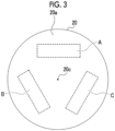
- Fig. 3 is a plan view showing the entire substrate 20. As shown in Fig.
- the substrate 20 is, for example, a disk-shaped substrate which has a diameter of 200 mm.
- the substrate 20 includes the masks 25 of 130 pieces ⁇ 8 rows shown in Fig. 2 in the nozzle plate formation regions A, B, and C which has a size of 100 mm ⁇ 40 mm.
- the nozzle plate formation regions A, B, and C are disposed in a three-fold rotational symmetry with a normal line that passes through a center 20c of the substrate 20 as a rotational axis. That is, in the substrate 20, the three nozzle plate formation regions A, B, and C are disposed at intervals of 120° with the normal line as the rotational shaft.
- the substrate 20 is provided with a metal film 22 on a glass wafer 21.
- the surface of the metal film 22 is the conductive surface 20a of the substrate 20.
- the non-conductive mask 25 is formed on a part of the conductive surface 20a (refer to Fig. 4 ).
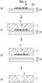
- Fig. 4 is a diagram showing a manufacturing step of the nozzle plate 10.
- Fig. 4 shows a cross unit of a part of the substrate 20 shown in Fig. 2 including only one mask 25.
- the substrate 20 in which the non-conductive mask 25 is formed on a part of the conductive surface 20a is provided.
- the electroforming step S1 in a state where the substrate 20 is immersed in the electrolytic solution, the metal layer 11 is grown on the conductive surface 20a by the metal precipitated from the electrolytic solution.
- the metal layer 11 grows on the conductive surface 20a, whereas no metal is precipitated on the surface of the non-conductive mask 25, and the metal layer 11 does not grow.
- the metal layer 11 gradually grows on the conductive surface 20a.
- the metal layer 11 grows on the non-conductive mask 25 side from the surface of the previously grown metal layer 11 so as to cover the edge portion of the mask 25.
- an opening is formed in the metal layer 11 with the opening center at a substantially center position of the mask 25. The opening is the nozzle 12.
- the thickness of the metal layer 11 increases, the metal layer 11 grows toward the center of the mask 25.
- the opening diameter of the nozzle 12 also gradually decreases.
- the diameter of the mask 25 is determined such that the nozzle 12 has a desired opening diameter in a case where the metal layer 11 is grown to have a desired thickness.
- the growth of the metal layer 11 on the mask 25 is larger at a position closer to the conductive surface 20a. Therefore, as shown in Fig. 4 , the opening diameter of the nozzle 12 is smaller at a position closer to the conductive surface 20a and is larger at a position away from the conductive surface 20a.
- the cross unit of the metal layer 11 forming an inner wall surface of the nozzle 12 is arc-shaped. For example, as a reference of a target opening diameter of the nozzle 12, the opening diameter of the nozzle 12 close to the conductive surface 20a is set. Then, the diameter of the mask 25 is determined such that the opening diameter of the reference nozzle 12 is the target opening diameter.
- the thickness t of the metal layer 11 is, for example, about 50 ⁇ m.
- the metal layer 11 is peeled off from the substrate 20 (peeling step S2).
- the mask 25 is peeled off from the substrate 20 together with the metal layer 11.
- Fig. 5 shows an example of the electroforming apparatus 30 used in the electroforming step S1.
- the electroforming apparatus 30 comprises an electroforming tank 32, a substrate holding mechanism 35, an anode 39, and a circulation mechanism 40 of an electrolytic solution 34.
- the electroforming tank 32 stores the electrolytic solution 34.
- the anode 39 is disposed on a part of the inner wall surface of the electroforming tank 32.
- the substrate 20 is immersed in the electrolytic solution 34 of the electroforming tank 32.
- the substrate 20 is disposed in the electrolytic solution 34, in a posture in which the conductive surface 20a faces the anode 39.
- the anode 39 is configured to include an electroforming metal such as nickel pellets and has a size by which the anode 39 is capable of facing the entire region of the conductive surface 20a on the substrate 20. Electroforming is performed on the substrate 20 in a state where the conductive surface 20a of the substrate 20 faces the anode 39.
- a part of the side wall of the electroforming tank 32 is tilted.
- the tilt direction of the side wall is a direction in which the upper opening becomes wider than the opening on the bottom surface of the electroforming tank 32 due to the tilt of the side wall.
- the tilt angle of the side wall is, for example, in a range of about 40° to about 50° with respect to the horizontal direction.
- the anode 39 is disposed along the inner wall surface of the tilted side wall in a tilted posture with respect to the horizontal direction.
- the substrate holding mechanism 35 includes a holding part 36, a rotational shaft 37, and a rotation device 38.
- the holding part 36 holds the substrate 20 from the opposite surface side of the conductive surface 20a of the substrate 20.
- the rotational shaft 37 is attached to the rear surface of the holding part 36 and extends in the normal direction of the rear surface of the holding part 36.
- the rotation device 38 rotates the holding part 36 through the rotational shaft 37.
- the holding part 36 holds the substrate 20 in the electroforming tank 32 such that the conductive surface 20a of the substrate 20 faces the anode 39. That is, in the substrate 20, the conductive surface 20a is disposed in a vertically downward posture.
- the vertically downward posture means a posture in which the tilt angle of the conductive surface 20a with respect to the horizontal direction is equal to or greater than 0° and less than 90°.
- the tilt angle is greater than 0°
- the conductive surface 20a is disposed in a posture in which the conductive surface 20a is horizontally tilted.
- the holding part 36 holds the substrate 20 by such that the center coincides with the rotational shaft 37.
- the substrate 20 rotates integrally with the holding part 36 through the rotational shaft 37, with the center coinciding with the rotational shaft 37 as the center of rotation.
- the substrate 20 is set in the holding part 36 outside the electroforming tank 32, and is immersed in the electroforming tank 32 in a state of being held by the holding part 36. Then, electroforming is performed while the substrate 20 is rotated about an axis extending in the normal direction from a center position in the plane of the conductive surface 20a.
- the conductive surface 20a of the substrate 20 is used as a cathode, and the conductive surface 20a serving as a cathode and the anode 39 including the electroforming metal are energized.
- the electroforming metal of the anode 39 is electrolyzed and is dissolved in the electrolytic solution 34 as electric ions.
- the metal layer 11 is formed by electrodepositing the metal precipitated from the electrolytic solution 34 on the conductive surface 20a serving as a cathode.
- the circulation mechanism 40 includes a reservoir 41, a discharge pipe 42, a valve 43, a pump 44, a filter 46, a supply pipe 47, and a nozzle 48.
- the circulation mechanism 40 circulates the electrolytic solution 34 stored in the electroforming tank 32 between the electroforming tank 32 and the reservoir 41 disposed outside the electroforming tank 32. Through the circulation, the electrolytic solution 34 is made to flow between the conductive surface 20a and the anode 39.
- the discharge pipe 42 and the supply pipe 47 form a circulation passage for the electrolytic solution 34 between the electroforming tank 32 and the reservoir 41.
- the discharge pipe 42 constitutes a returning pipe line in which the electrolytic solution 34 in the electroforming tank 32 is discharged and the discharged electrolytic solution 34 is returned to the reservoir 41 through the circulation passage.
- the supply pipe 47 constitutes a supply pipe line for supplying the electrolytic solution 34 from the reservoir 41 to the electroforming tank 32 in the circulation passage.
- One end of the discharge pipe 42 is disposed in the electroforming tank 32, and the other end thereof is connected to the reservoir 41.
- the electrolytic solution 34 which has an amount greater than a preset specified amount in the electroforming tank 32, is returned to the reservoir 41. Therefore, one end of the discharge pipe 42 is disposed at substantially the same height as the liquid surface of the specified amount of the electrolytic solution 34 with the opening facing upward. Thereby, the electrolytic solution 34 in excess of the specified amount in the electroforming tank 32 flows into the discharge pipe 42 and is returned to the reservoir 41 through the discharge pipe 42.
- One end of the supply pipe 47 is also disposed in the electroforming tank 32, and the other end thereof is connected to the reservoir 41.
- the nozzle 48 through which the electrolytic solution 34 is injected into the electroforming tank 32, is connected to one end of the supply pipe 47.
- the other end of the supply pipe 47 is connected to the lower part of the reservoir 41.
- the valve 43, the pump 44, and the filter 46 are disposed on the supply pipe line constituted of the supply pipe 47 in order from the reservoir 41 side which is the upstream side of the electrolytic solution 34 in the supply direction.
- the valve 43 opens and closes a supply passage. In a case where the supply passage is opened through the valve 43 in a state where the pump 44 is driven, the supply of the electrolytic solution 34 from the reservoir 41 to the electroforming tank 32 is started.
- the filter 46 filters the electrolytic solution 34.
- the electrolytic solution 34 that passes through the filter 46 is supplied into the electroforming tank 32 through the supply pipe 47.
- the nozzle 48 Through the nozzle 48, the electrolytic solution 34 is injected toward between the conductive surface 20a of the substrate 20 and the anode 39.
- the electrolytic solution 34 is circulated between the electroforming tank 32 and the reservoir 41 by using the circulation mechanism 40. Then, in the electroforming tank 32, the electrolytic solution 34 is injected from the nozzle 48 toward between the conductive surface 20a and the anode 39. Thereby, the electrolytic solution 34 is flowed in a direction in which the fluid pressure of the electrolytic solution 34 is applied toward the conductive surface 20a having the mask 25.
- the electroforming step S 1 is performed while the electrolytic solution 34 is flowed in such a manner.
- the electroforming is performed on the conductive surface 20a of the substrate.
- a substrate in which a movement start angle of a bubble attached to the surface of the mask 25 is equal to or less than 20° is used as the substrate 20 on which the non-conductive mask 25 is formed.
- the movement start angle is one of indicators indicating the surface characteristics of the mask 25, and is defined herein as follows.
- the movement start angle is a tilt angle of the surface of the mask 25 with respect to the reference posture in a case where a bubble of 3 microliters ( ⁇ L) attached to the mask 25 starts moving along the surface of the mask 25 due to buoyancy, in a case where a surface of the mask 25 is vertically downward and a horizontal posture is set as a reference posture in a state where the substrate 20 is immersed in water and the surface of the mask 25 is tilted from the reference posture.
- the surface of the mask 25 is parallel with the conductive surface 20a of the substrate 20 on which the mask 25 is formed. Therefore, the above-mentioned reference posture is obtained in a case where the substrate 20 is disposed such that the conductive surface 20a is vertically downward and is in a horizontal posture.
- a base material S which is a parallel plate having two main surfaces s1 and s2 parallel to each other, is disposed in water such that one main surface s1 is vertically downward and is horizontal.
- a fixing base 54 for fixing the base material S is immersed in water, and the fixing base 54 is provided such that a fixing surface 54a of the fixing base 54 is horizontal in water.
- the fixing base 54 is disposed such that the other main surface s2 of the base material S comes into contact with the fixing surface 54a.
- the base material S is disposed in the reference posture.
- the main surfaces s1 and s2 of the base material S are horizontal planes.
- the bubble 50 of 3 ⁇ L is brought into contact with the main surface s1 of the base material S.
- a dispensing nozzle (not shown in the drawing) is disposed below the main surface s1 of the base material S, and air of 3 ⁇ L is discharged toward the base material S. Thereby, the bubble 50 of 3 ⁇ L is generated, and the generated bubble 50 is brought into contact with the main surface s1 of the base material S.
- the base material S is gradually tilted together with the fixing base 54 and the fixing surface 54a from the reference posture shown in the upper part of Fig. 6 .
- the angle formed by the fixing surface 54a in a case where the bubble 50 starts moving along the main surface s1 of the base material S in the horizontal direction is measured.
- the main surface s1 of the base material S is parallel with the fixing surface 54a. Therefore, the measured angle of the fixing surface 54a is an angle of the main surface s1 of the base material S, and corresponds to the movement start angle in a case where the bubble 50 starts moving along the main surface s1.
- the measurement of the angle formed between the fixing surface 54a and the horizontal direction in a case where the bubble 50 starts moving along the main surface s1 is performed, for example, at least three times, and an average value thereof is set as the movement start angle ⁇ of the bubble with respect to the base material.
- the water used for the measurement is distilled water, and the bubble is an air bubble.
- the movement start angle ⁇ at which the bubble moves from the surface of the mask 25 is one of the indicators indicating the surface characteristics of the mask 25, and is used as an indication that the bubble 50 is likely to remain on the surface of the mask 25.
- a larger movement start angle ⁇ means that the bubble 50 is more likely to remain on the surface of the mask 25, and a smaller movement start angle ⁇ means that the bubble 50 is less likely to remain on the surface of the mask 25.
- the movement start angle ⁇ of the bubble of 3 ⁇ L is equal to or less than 20°, attachability of the bubble 50 to the surface of the mask 25 is low. Therefore, the bubble 50 is likely to move.
- the bubble 50 of 3 ⁇ L corresponds to a spherical bubble 50 having a diameter of 4.6 mm. As the size of the bubble 50 is smaller, the buoyancy is smaller. Therefore, the bubble 50 tends to be less likely to move. According to the study by the inventors of the present disclosure, regarding the surface of the mask 25 in which the movement start angle ⁇ of the bubble 50 of 3 ⁇ L is equal to or less than 20°, it is presumed that there is the following effect. Even a minute bubble 50 having a diameter of several tens of ⁇ m or less is likely to move, and attachment of the minute bubble 50 to the surface of the mask 25 is suppressed.
- the movement start angle ⁇ in water is specified herein, there is a correlation between the movement start angle ⁇ of the bubble 50 in water and the movement start angle ⁇ of the bubble 50 in the electrolytic solution during electroforming. That is, the movement start angle ⁇ in the electrolytic solution is also large in a case where the movement start angle ⁇ in water is large, and the movement start angle ⁇ in the electrolytic solution is also large in a case where the movement start angle ⁇ in water is large. According to the study by the inventors of the present disclosure, it is presumed that there is the following effect.
- the movement start angle ⁇ of the bubble 50 of 3 ⁇ L on the surface of the mask 25 in water is equal to or less than 20°, it is possible to suppress remaining of the bubble 50 and attachment of the minute bubble 50 having a diameter of several tens of ⁇ m or less on the surface of the same mask 25 in the electrolytic solution during electroforming.
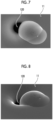
- Figs. 7 to 10 show electron beam microscope images showing states of the molding defects of the nozzle 120 in a case where a nozzle plate having the nozzle 120 for an inkjet printer is manufactured by electroforming by a conventional method.
- Fig. 7 shows an image obtained by observing the nozzle 120 from the front on the growth surface side
- Fig. 8 shows an image obtained by observing the nozzle 120 shown in Fig. 7 from an oblique direction.
- the nozzle 120 should have a circular opening shape, but the nozzle 120 in which the molding defect has occurred has a crescentic opening shape as shown in Figs. 7 and 8 .
- a part that appears black is the nozzle 120.
- a part of the metal layer 11 that grows so as to cover the edge portion of the mask 25 is abnormally swelled as compared with the other part thereof.
- Fig. 9 shows an image obtained by observing the nozzle 120 shown in Fig. 7 and Fig. 8 from the opposite surface side. In Fig. 9 , it is more clearly shown that the opening shape of the nozzle 120 is the crescent shape. Further, in Fig. 9 , a region in the white frame defined by the circular white frame surrounding the nozzle 120 having a crescent shape is a region corresponding to the shape of the circular mask 25. In the region, the surface is recessed by a thickness of the mask 25 from the surface around the region.
- the hole 121 is formed in the vicinity of the nozzle 120 having a crescent shape.
- a hole 121 is located at a position corresponding to a part where the metal layer is raised on the growth surface side of the metal layer 11.
- Fig. 10 shows an enlarged image of the hole 121.
- the hole 121 is formed by a cavity formed inside the metal layer 11. That is, as shown in Figs. 7 and 8 , it is considered that the abnormally bulging part observed on the growth surface side of the metal layer 11 is caused by formation of a cavity inside. Then, it is presumed that the opening part of the cavity is the hole 121 shown in Figs. 9 and 10 .
- the cause of the cavity in the metal layer 11 is the bubble 50 attached to the edge portion of the mask 25. That is, since electroforming is performed in a state where the bubble 50 is attached, the bubble 50 is entrained and the metal layer 11 grows. As a result, a cavity is formed in the metal layer 11, and it is considered that the cavity causes an abnormal swelling of the metal layer 11.
- the substrate 20 on which the non-conductive mask 25 is formed the substrate 20 having the following configuration is used.
- a posture of a surface of the mask 25 which is vertically downward and horizontal is set as a reference posture in a state where the substrate 20 is immersed in water and the surface of the mask 25 is tilted from the reference posture
- a movement start angle which is a tilt angle of the surface of the mask 25 with respect to the reference posture in a case where the bubble of 3 ⁇ L attached to the mask 25 starts moving along the surface of the mask 25 due to buoyancy, is equal to or less than 20°.
- the bubble can be easily removed from the surface of the mask 25 as compared with the conventional case. Therefore, the molding defect of the nozzle 12 (an example of the opening of metal molded product) of the nozzle plate 10, which is an example of a metal molded product, can be reduced. In particular, even a minute bubble having a diameter of several tens of ⁇ m or less can be easily removed. Therefore, in a case of manufacturing the metal molded product having the nozzles 12 (an example of openings of the metal molded product) of 100 ⁇ m or less, such as the nozzle plate 10, there is a high effect of suppressing molding defects of the openings.
- the substrate 20 in which the movement start angle ⁇ of the surface of the mask 25 is smaller.
- the movement start angle of the surface of the mask 25 By making the movement start angle of the surface of the mask 25 smaller than that of the conductive surface 20a, as compared with a case where the movement start angles of the surface of the mask 25 and the conductive surface 20a are the same, the bubble 50 is likely to move from the surface of the mask 25 toward the conductive surface 20a. Therefore, it is possible to more reliably reduce molding defects of openings.
- the substrate 20 of the present example has the following configuration.
- the conductive surface 20a is a flat surface, and the mask 25 is formed on the flat conductive surface 20a.
- the mask 25 is disposed to be projected with respect to the conductive surface 20a.
- the mask 25 may be formed at a position lower by one stage than the conductive surface 20a of the substrate 20, and a portion where the mask 25 is formed may be recessed.
- the heights of the conductive surface 20a and the surface of the mask 25 may be the same, and both surfaces may be coplanar.
- the metal molded product manufacturing method according to the second embodiment also includes an electroforming step of using the substrate 20 in which the non-conductive mask 25 is formed on a part of the conductive surface 20a.
- the electroforming step in a state where the substrate 20 is immersed in the electrolytic solution 34, the metal layer 11 is grown on the conductive surface 20a by the metal precipitated from the electrolytic solution 34, and the opening is manufactured at a position corresponding to the mask 25.
- a manufacturing method of manufacturing the nozzle plate 10 as the metal molded product will be described.
- the entire flow of the manufacturing step shown in Fig. 4 is basically the same as that of the first embodiment described above. In the following description, only the differences will be described, and detailed description of the same parts will be omitted.
- the substrate 20 on which the non-conductive mask 25 is formed the substrate 20 that satisfies the following conditions as the condition about the contact angle of the bubble 50 with respect to the mask 25 is used.
- the contact angle of the bubble 50 is defined as follows.
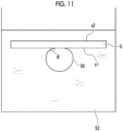
- the base material S which is a parallel plate having two main surfaces s1 and s2 parallel to each other, is disposed in water in a water tank, in which water 52 is stored, such that one main surface s1 is vertically downward and horizontal.
- the fixing base 54 (not shown in Fig. 11 ) shown in Fig. 6 is used and is disposed such that the other main surface s2 of the base material S comes into contact with the fixing surface 54a.
- the base material S is disposed in the reference posture.
- the main surfaces s1 and s2 of the base material S are horizontal planes.
- the bubble 50 of 3 ⁇ L is brought into contact with the main surface s1 of the base material S.
- the contact angle ⁇ of the bubble 50 means an angle between the base material S and the tangent line of the bubble 50 at the end part where the bubble 50 is in contact with the base material S in a case where the bubble 50 being in contact with the base material S is observed from the horizontal direction.
- a camera of a contact angle measurement device is used to image the horizontally disposed base material S and the bubble 50 being in contact with the surface of the base material S from the horizontal direction.
- the measurement is performed, for example, at least three times, and an average value thereof is set as the contact angle ⁇ .
- the first contact angle ⁇ 1 is a contact angle on a side of the movement direction in which the bubble 50 moves at the above-mentioned movement start angle ⁇ (refer to Fig. 6 ), and the contact angle is also referred to as a forward contact angle.
- the second contact angle ⁇ 2 is a contact angle on a side opposite to the movement direction in which the bubble moves immediately before the movement start angle, and the contact angle is also referred to as a backward contact angle.
- the bubble 50 of 3 ⁇ L is attached to the surface of the base material S, and together with the fixing base 54, the base material S is tilted from the reference posture (not shown in Fig. 12 , refer to Fig. 6 ), in a direction in which an angle formed between the fixing surface 54a and the horizontal plane increases.
- the contact angle of the bubble 50 is measured in a case where the tilt angle of the main surface s1 of the base material S with respect to the horizontal direction is the movement start angle ⁇ , that is, immediately before the bubble 50 starts moving.
- a state in which the base material S is gradually tilted together with the fixing base 54 is imaged from a horizontal direction, and an angle, which is formed between the base material S and the tangent line at the end part on the side of the movement direction of the bubble in an image immediately before the bubble 50 leave the base material S, and an angle, which is formed between the base material S and the tangent line at the end part on the side opposite to the movement direction of the bubble 50 are obtained through the image analysis.
- the measurement is performed at least three times for each angle, and the average values thereof are set as the first contact angle ⁇ 1 and the second contact angle ⁇ 2, respectively.
- the angular difference ⁇ cp between the first contact angle ⁇ 1 and the second contact angle ⁇ 2 obtained in such a manner is obtained.
- the angular difference ⁇ between the first contact angle ⁇ 1 and the second contact angle ⁇ 2 at the movement start angle at which the bubble 50 moves from the surface of the mask 25 is one of the indicators indicating the surface characteristics of the mask 25, and is used as an indication that the bubble 50 is likely to remain on the surface of the mask 25.
- the angular difference ⁇ between the first contact angle ⁇ 1 and the second contact angle ⁇ 2 indicates asymmetry between the bubble 50 on the side of the movement direction and the side opposite to the movement direction.
- the attachability of the bubble 50 to the surface of the mask 25 is weak. Therefore, the bubble 50 is likely to move. As the size of the bubble 50 is smaller, the buoyancy is smaller. Therefore, the bubble 50 tends to be less likely to move. According to the study by the inventors of the present disclosure, regarding the surface in which the angular difference of the bubble of 3 ⁇ L is equal to or less than 30°, there is the following effect. Even a minute bubble 50 having a diameter of several tens of ⁇ m or less is likely to move, and attachment of the minute bubble to the surface of the mask is suppressed.
- the angular difference of the bubble 50 immediately before the bubble 50 starts moving from the surface of the mask 25 in water is defined herein, there is a correlation between the angular difference in water and the angular difference in the electrolytic solution during electroforming. That is, in a case where the angular difference in water is large, the angular difference in the electrolytic solution is large, and in a case where the angular difference in water is large, the angular difference in the electrolytic solution is also large. According to the study by the inventors of the present disclosure, there is the following effect.
- the angular difference immediately before the start of movement of the bubble of 3 ⁇ L on the surface of the mask 25 in water is equal to or less than 30°, it is possible to suppress remaining of the bubble and attachment of the minute bubble having a diameter of several tens of ⁇ m or less on the surface of the same mask 25 in the electrolytic solution during electroforming.
- the substrate 20 on which the non-conductive mask 25 is formed the substrate 20 having the following configuration is used.
- a posture in which the surface of the mask 25 is vertically downward and is horizontal is set as a reference posture in a state where the substrate 20 is immersed in water
- the angular difference ⁇ cp between the first contact angle ⁇ 1 and the second contact angle ⁇ 2 of the bubble 50 immediately before the bubble 50 of 3 ⁇ L attached to the surface of the mask 25 starts moving by tilting the surface of the mask 25 from the reference posture is equal to or less than 30°.
- the bubble 50 is likely to move from the surface of the mask 25 toward the conductive surface 20a. Therefore, it is possible to more reliably reduce molding defect of the opening.
- the substrate 20 in which the movement start angle ⁇ of the bubble 50 on the surface of the mask 25 is equal to or less than 20° is used as the surface characteristic of the mask 25.
- the second embodiment is an embodiment which uses the substrate 20 of which the angular difference ⁇ cp which is a difference between the first contact angle ⁇ 1 and the second contact angle ⁇ 2 of the bubble on the surface of the mask 25 as the surface characteristic of the mask 25 is equal to or less than 30°.
- the substrate 20 on which the non-conductive mask 25 is formed it is preferable to use the substrate 20 having the surface characteristics of each of the masks 25 of the first and second embodiments.
- the posture of the surface of the mask 25 is vertically downward and horizontal is set as the reference posture in a state where the substrate 20 is immersed in water, and the surface of the mask 25 is tilted from the reference posture.
- the movement start angle is equal to or less than 20°, which is a tilt angle with respect to the reference posture of the surface of the mask 25 in a case where the bubble of 3 microliters ( ⁇ L) attached to the surface of the mask 25 starts moving along the surface of the mask 25 due to buoyancy.
- the contact angle of the bubble immediately before the bubble of 3 ⁇ L attached to the surface of the mask 25 in the reference posture starts moving by tilting the surface of the mask 25 from the reference posture assuming that the contact angle on the side of the movement direction in which the bubble moves due to the buoyancy is the first contact angle and the contact angle on the side opposite to the movement direction is the second contact angle, the angular difference is 30°, which is a difference between the first contact angle and the second contact angle.
- the contact angle ⁇ of the bubble 50 attached to the mask 25 in the reference posture is equal to or greater than 130°. It is more preferable that the contact angle ⁇ of the bubble attached to the mask 25 in the reference posture is equal to or greater than 130°.
- the contact angle ⁇ of the bubble 50 the more the bubble on the surface of the mask 25 is likely to move, and the smaller the contact angle of the bubble 50, the more the bubble is likely to remain on the surface of the mask 25.
- the contact angle ⁇ of the bubble 50 is equal to or greater than 130°
- the attachment force of the bubble 50 to the surface of the mask 25 is weak. Therefore, the bubble 50 is likely to move.
- the surface in which the contact angle ⁇ of the bubble 50 is equal to or greater than 130° the following effect is further improved. Even a minute bubble 50 having a diameter of several tens of ⁇ m or less is likely to move, and attachment of the minute bubble 50 to the surface of the mask 25 is suppressed.
- the contact angle of the bubble 50 in water is defined herein, there is a correlation between the contact angle of the bubble 50 in water and the contact angle of the bubble 50 in the electrolytic solution during electroforming. That is, in a case where the contact angles of the bubbles in water are large, the contact angles of the bubbles in the electrolytic solution are also large, and in a case where the contact angles of the bubbles in water are large, the contact angles of the bubbles in the electrolytic solution are also large.
- the contact angle of the bubble 50 of 3 ⁇ L attached to the mask 25 in the reference posture is equal to or greater than 130°, it is possible to suppress the remaining of the bubble 50 on the surface of the same mask 25 in the electrolytic solution during electroforming. As a result, there is an effect of suppressing attachment of the minute bubble having a diameter of several tens of ⁇ m or less.
- the molding defect of the nozzle 12 can be suppressed.
- the substrate 20 on which the non-conductive mask 25 is formed the substrate 20 in which the contact angle ⁇ of the bubble 50 attached to the mask 25 in the reference posture is equal to or greater than 130° is used.
- the contact angle of the bubble 50 with respect to the surface of the mask 25 in water is large. Further, in a case where the surface of the mask 25 is hydrophobic, the contact angle of the bubble 50 with respect to the mask surface in water is small. That is, the more hydrophilic the surface of the mask 25 is, the larger the contact angle of the bubble 50 is, and the higher the effect of suppressing the attachment of the bubble 50 is.
- the contact angle ⁇ of the bubble 50 on the surface of the mask 25 is smaller than that of the conductive surface 20a, as compared with a case where the contact angles ⁇ of the surface of the mask 25 and the conductive surface 20a are the same, the bubble 50 is likely to move from the surface of the mask 25 toward the conductive surface 20a. Therefore, it is possible to more reliably reduce molding defects of openings in the metal molded product.
- the substrate 20 is disposed in the electrolytic solution in a posture in which the conductive surface 20a is vertically downward.
- the substrate 20 may be disposed in a posture in which the conductive surface 20a is vertically upward.
- the bubble 50 is not pressed by the substrate 20. Therefore, the bubble 50 is likely to move due to buoyancy as compared with a case where the conductive surface 20a is vertically downward. Therefore, bubbles on the surface of the mask can be reduced more reliably.
- a pressing force is applied by the substrate 20 to the bubble 50.
- the bubble 50 is less likely to move as compared with a case where the conductive surface 20a is vertically upward.
- the substrate 20 described in the above-mentioned embodiment even in a case where the conductive surface 20a is disposed to be vertically downward, attachment of a bubble to the surface of the mask 25 can be suppressed. As a result, it is possible to reduce molding defects of openings in the metal molded product. Further, by setting the conductive surface 20a in the vertically downward posture, it is possible to suppress foreign matter in the electrolytic solution falling from above in the vertical direction from being attached to the conductive surface as compared with a case of the vertically upward posture.
- the tilt angle of the conductive surface having the mask 25 with respect to the horizontal direction is equal to or less than 60°. Attachment of foreign matter onto the conductive surface can be more reliably suppressed.
- the electroforming is performed while the substrate 20 is rotated about an axis extending in the normal direction from the center position in the plane of the conductive surface by using the electroforming apparatus shown in Fig. 5 .
- the electroforming may be performed while the substrate 20 is held at a fixed position without rotating the substrate 20.
- the electroforming step of the metal molded product manufacturing method according to the above-mentioned embodiment is performed while the electrolytic solution is flowed in a direction in which the fluid pressure of the electrolytic solution 34 is applied toward the conductive surface 20a of the substrate 20.
- the electroforming step may be performed without causing the flow.
- by performing the electroforming step while flowing the electrolytic solution in a direction in which the fluid pressure of the electrolytic solution is applied toward the conductive surface 20a attachment of foreign matter onto the surface of the mask 25 and the conductive surface 20a can be suppressed. Further, an effect of removing the bubble 50 remaining on the surface of the mask 25 can also be obtained.
- the substrate 20 may have a configuration in which the metal film 22 is provided on one surface of the glass wafer 21.
- the substrate 20 can be obtained by forming the metal film 22 such as nickel or copper on the glass wafer 21 through sputtering, vacuum vapor deposition, or the like.
- the metal substrate may be used as the substrate 20 having the conductive surface 20a. In a case of a metal substrate, it is not necessary to separately form the metal film by sputtering or the like.
- the non-conductive material which is a material of the non-conductive mask 25 may be a metal oxide or a photosensitive resin.
- a vapor deposition mask having openings having a desired mask shape is disposed on the substrate 20 so as to face the conductive surface 20a of the substrate 20, and vacuum vapor deposition is performed. Thereby, it is possible to form the mask 25.
- the metal oxide include silicon oxide.
- the mask 25 remains on the substrate side at the time of peeling the metal layer in the peeling step described in the metal molded product manufacturing method according to the above-mentioned embodiment. Therefore, the substrate in which the non-conductive mask 25 is formed on a part of the conductive surface can be repeatedly used a plurality of times.
- the non-conductive mask 25 is subjected to the hydrophilic treatment before the electroforming step.
- the movement start angle ⁇ can be set to be equal to or less than 20°, which is the tilt angle with respect to the reference posture of the surface of the mask 25 in a case where the bubble 50 of 3 ⁇ L attached to the surface of the mask 25 starts moving along the surface of the mask 25 due to buoyancy.
- the angular difference ⁇ can be set to be equal to or less than 30°, which is a difference between the first contact angle ⁇ 1 and the second contact angle ⁇ 2 of the bubble immediately before the bubble of 3 ⁇ L starts moving by tilting the surface of the mask 25 from the reference posture.
- the movement start angle ⁇ which is a tilt angle with respect to a reference posture of the surface of the mask 25 in a case where bubble 50 of 3 ⁇ L attached to the surface of the mask 25 starts moving along the surface of the mask 25 due to buoyancy, is equal to or less than 20°.
- the angular difference ⁇ cp can be set to be equal to or less than 30°, which is a difference between the first contact angle ⁇ 1 and the second contact angle ⁇ 2 of the bubble 50 immediately before the bubble 50 of 3 ⁇ L starts moving by tilting the surface of the mask 25 from the reference posture.
- the method of the hydrophilic treatment is not particularly limited, but plasma treatment or ultraviolet ozone treatment is preferable.
- the hydrophilic treatment can be integrally and uniformly performed over the entire region of the substrate 20.
- the metal molded product manufacturing method of each of the above-mentioned embodiments may include a mask forming step of forming the mask on the conductive surface 20a.
- An example mask forming step includes a photosensitive resin coating step, an exposure step, and a development step.
- the hydrophilic treatment of the photosensitive resin is performed at any stage after the coating step. In particular, it is preferable to perform the hydrophilic treatment on the photosensitive resin after the coating step and before the development step.
- the mask provision step in the above-mentioned embodiment includes a mask forming step.
- a specific example of the mask forming step will be described with reference to Fig. 13 .
- the coating step S11, the hydrophilic treatment S12, the exposure step S13, and the development step S14 are performed in this order. Consequently, the hydrophilic treatment is performed before the exposure step.
- the photosensitive resin film 24 is applied and formed on the metal film 22 on the glass wafer 21, that is, the conductive surface 20a of the substrate 20.
- the hydrophilic treatment S12 the hydrophilic treatment is performed on the entire surface of the photosensitive resin film 24.
- the hydrophilic treatment the plasma treatment or the ultraviolet ozone treatment is performed.
- a mask 26 for forming a pattern is disposed on the photosensitive resin film 24, and the photosensitive resin film 24 is exposed to the pattern.
- the exposed photosensitive resin film 24 is developed to obtain the substrate 20 provided with the mask 25 on the conductive surface 20a.
- the hydrophilic treatment is performed on the photosensitive resin film 24. Therefore, in a case where the surface of the mask 25 is tilted from the reference posture in a state where the substrate 20 is immersed in water, the movement start angle ⁇ is equal to or less than 20°, which is a tilt angle with respect to the reference posture of the surface of the mask 25 in a case where the bubble 50 of 3 ⁇ L attached to the surface of the mask 25 starts moving along the surface of the mask 25 due to buoyancy. Further, the hydrophilic treatment is performed on the surface of the photosensitive resin film 24, that is, the mask 25. Therefore, the posture of the surface of the mask 25 which is vertically downward and horizontal is set as the reference posture in a state where the substrate 20 is immersed in water.
- the angular difference ⁇ cp is equal to or less than 30°, which is a difference between the first contact angle ⁇ 1 and the second contact angle ⁇ 2.
- the coating step S21, the exposure step S22, the hydrophilic treatment S23, and the development step S24 are performed in this order. Consequently, the hydrophilic treatment is performed after the exposure step S22 and before the development step S24.
- the photosensitive resin film 24 is uniformly coated on the metal film 22 on the glass wafer 21, that is, the conductive surface 20a of the substrate 20.
- the mask 26 for forming a pattern is disposed on the photosensitive resin film 24, and the photosensitive resin film 24 is exposed to the pattern.
- the hydrophilic treatment S23 the hydrophilic treatment is performed on the entire surface of the photosensitive resin film 24.
- the hydrophilic treatment the plasma treatment or the ultraviolet ozone treatment is performed.
- the exposed photosensitive resin film 24 is developed to obtain the substrate 20 provided with the mask 25 on the conductive surface 20a.
- the hydrophilic treatment is performed on the photosensitive resin film 24. Therefore, in a case where the surface of the mask 25 is tilted from the reference posture in a state where the substrate 20 is immersed in water, the movement start angle is equal to or less than 20°, which is a tilt angle with respect to the reference posture of the surface of the mask 25 in a case where the bubble 50 of 3 ⁇ L attached to the surface of the mask 25 starts moving along the surface of the mask 25 due to buoyancy. Further, the hydrophilic treatment is performed on the surface of the photosensitive resin film 24, that is, the mask 25. Therefore, the posture of the surface of the mask 25 which is vertically downward and horizontal is set as the reference posture in a state where the substrate 20 is immersed in water.
- the contact angle of the bubble 50 immediately before the bubble 50 of 3 ⁇ L attached to the surface of the mask 25 in the reference posture starts moving by tilting the surface of the mask 25 from the reference posture assuming that the contact angle on the side of the movement direction in which the bubble moves due to buoyancy is the first contact angle ⁇ 1 and the contact angle on the side opposite to the movement direction is the second contact angle ⁇ 2, the angular difference ⁇ cp is equal to or less than 30°, which is a difference between the first contact angle ⁇ 1 and the second contact angle ⁇ 2.
- the hydrophilic treatment is performed before the exposure step or after the exposure step and before the development step.
- the hydrophilic treatment may performed before the exposure step, after the exposure step, before the development step, or after the development step.
- the surface of the mask 25 is made hydrophilic, and the above-mentioned effect can be obtained.
- by performing the hydrophilic treatment before the exposure step or after the exposure step and before the development step it is possible to suppress a decrease in yield due to a phenomenon that the metal layer 11 is peeled off from the conductive surface during electroforming.
- a coated photosensitive resin film, which was not subjected to exposure, development, or cleaning treatment after coating formation, a developed and cleaned photosensitive resin film, which was subjected to exposure, development, or cleaning treatment, and a Ni sputter film were provided.
- the water contact angle before and after the ultraviolet ozone treatment as the hydrophilic treatment was measured.
- the Ni sputter film is an example of the metal film forming the conductive surface of the substrate.
- a low-pressure mercury lamp (emission main wavelength 254 nm, and output 200 W) was used as the ultraviolet ozone treatment, and irradiation was performed for 20 minutes.
- the water contact angle was measured by using a contact angle meter DMo-501 manufactured by Kyowa Interface Science Co., Ltd., and an average value at 10 points was taken. Table 1 shows the results thereof. [Table 1] Before hydrophilic treatment water contact angle (°) water contact angle (°) Coated photosensitive resin 83.1 17.8 Developed and cleaned photosensitive resin 80.3 17.8 Ni sputter film 26.7 31.5
- the photosensitive resin was hydrolyzed by the ultraviolet ozone treatment, and the water contact angle was significantly decreased.
- the effect on the ultraviolet ozone treatment did not change significantly before and after the development cleaning.
- the Ni-sputter film had no effect of hydrophilization by the ultraviolet ozone treatment, and the result thereof was that the water contact angle was slightly increased. Consequently, in the hydrophilic treatment, substantially the same hydrophilization effect was obtained even in a state where the exposure and development treatments were not performed.
- the contact angle ⁇ , the movement start angle ⁇ , and the angular difference ⁇ cp of the bubble 50 of 3 ⁇ L in water were measured.
- Fig. 15 shows the results of measuring the contact angle ⁇ of bubble of 3 ⁇ L in water for each of the Ni sputter film, the photosensitive resin film, and the photosensitive resin film subjected to the ultraviolet ozone treatment as the hydrophilic treatment.
- the contact angle was measured three times for each film.
- a range indicated by the bar is a range of a minimum value or more and a maximum value or less of the three-times measured values, and a dot indicates an average value of the three-times measured values.
- the average value of the three-times measured values is set as the contact angle ⁇ of each film.
- the contact angle ⁇ of the bubble with respect to the Ni sputter film was 125°
- the contact angle ⁇ of the bubble with respect to the photosensitive resin film not subjected to the hydrophilic treatment was 115°
- the contact angle ⁇ of the bubble with respect to the photosensitive resin film subjected to the ultraviolet ozone treatment was 145°.
- the contact angle ⁇ of the bubble with respect to the photosensitive resin film not subjected to the hydrophilic treatment is less than that of the Ni sputter film.
- the contact angle ⁇ of the bubble with respect to the photosensitive resin film subjected to the hydrophilic treatment is greater than the contact angle ⁇ of the bubble with respect to the photosensitive resin film and the Ni sputter film not subjected to the hydrophilic treatment. Consequently, the effect of increasing the contact angle ⁇ of the bubble was obtained by the hydrophilic treatment.
- Fig. 16 shows the results of measuring the movement start angle ⁇ of the bubble for each of the Ni sputter film, the photosensitive resin film, and the photosensitive resin film which is subjected to the ultraviolet ozone treatment as the hydrophilic treatment.
- the movement start angle was measured three times for each film.
- a range indicated by the bar is a range of a minimum value or more and a maximum value or less of the three-times measured values, and a dot indicates an average value of the three-times measured values.
- the average value of the three-times measured values is set as the movement start angle ⁇ of each film.
- the movement start angle ⁇ of the Ni sputter film was 38°
- the movement start angle ⁇ of the photosensitive resin film not subjected to the hydrophilic treatment was 48°
- the movement start angle ⁇ of the photosensitive resin film subjected to the ultraviolet ozone treatment was substantially 0°.
- the movement start angle ⁇ of the photosensitive resin film not subjected to the hydrophilic treatment was greater than that of the Ni sputter film, and the bubble did not move even in a case where tilted up to 60° in some cases.
- the movement start angle ⁇ of the photosensitive resin which was subjected to the hydrophilic treatment was approximately 0°. In the photosensitive resin subjected to the hydrophilic treatment, bubbles were moving before the angle of the substrate was tilted, and a high effect of improving the mobility of the bubbles on the photosensitive resin film by performing the hydrophilic treatment was obtained.
- Fig. 17 is a diagram schematically showing a shape of a bubble in each film during measurement of the angular difference.
- Fig. 17A shows a shape of a bubble on the Ni sputter film in a case of measuring the angular difference.
- Fig. 17B shows a shape of a bubble on the photosensitive resin film not subjected to the hydrophilic treatment in a case of measuring the angular difference.
- Fig. 17C shows a shape of a bubble on the photosensitive resin film subjected to the hydrophilic treatment in a case of measuring the angular difference.
- the angular difference ⁇ cp was 44° for the photosensitive resin film that had not been subjected to the hydrophilic treatment, 36° for the Ni sputter film, and approximately 0° for the photosensitive resin film that had been subjected to the hydrophilic treatment.
- the angular difference ⁇ cp of the photosensitive resin film not subjected to the hydrophilic treatment is greater than that of the Ni sputter film.
- the angular difference ⁇ cp of the photosensitive resin subjected to the hydrophilic treatment was approximately 0°, which was smaller than that of the photosensitive resin film and the Ni sputter film not subjected to the hydrophilic treatment.
- the effect of improving the mobility of a bubble on the photosensitive resin film by performing the hydrophilic treatment is also shown from the angular difference ⁇ cp.
- a nozzle plate was manufactured through the metal molded product manufacturing method according to Example 1.
- the manufacturing method according to Example 1 was as follows.
- the Ni film was sputter-deposited on the glass wafer to obtain a substrate made of the Ni film and having the conductive surface. Then, a mask for forming a nozzle was formed on the surface of the Ni film of the substrate by the following mask forming step to provide a substrate having three nozzle plate formation regions A, B, and C as shown in Fig. 3 .
- the nozzle plate formation regions A, B, and C were 100 mm ⁇ 40 mm, and 130 masks having a diameter of 150 ⁇ m and a mask thickness of 2 ⁇ m were arranged in 8 rows.
- a photosensitive resin film is applied and formed on the surface of the Ni film on the glass wafer (coating step), a mask for forming a pattern was disposed on the photosensitive resin film, and the photosensitive resin was exposed to the pattern (exposure step), and developed (development step) to form a mask. Then, the surface of the mask and the Ni film was subjected to the hydrophilic treatment with oxygen plasma.
- the water contact angle of the mask surface was 8.4°.
- the contact angle of the bubble on the mask surface in water was 148°, the movement start angle was 0°, and the angular difference between the first contact angle and the second contact angle was 0°.
- a substrate having a non-conductive mask formed on a part of the conductive surface formed of the Ni film obtained in the above steps was used, the electroforming apparatus described with reference to Fig. 5 was used, and the Ni electroforming is performed while the glass wafer is rotated in the electroforming tank. Thereby, a metal layer was grown on the Ni film of the substrate (electroforming step). The electroforming was performed until the thickness of the metal layer became approximately 50 ⁇ m and the opening diameter on the mask reached a desired value (design value 40 ⁇ m).
- the metal layer was peeled from the substrate (peeling step), and in the peeling step, the mask attached to a part of the metal layer was removed (mask removing step) to provide the nozzle plate of Example 1 formed of the metal layer.
- a nozzle plate was manufactured through the metal molded product manufacturing method according to a comparative example.
- Example 1 In the manufacturing method according to the comparative example, in the manufacturing step of Example 1, the hydrophilic treatment was not performed in the mask forming step. A nozzle plate of the comparative example was provided in a similar manner as in Example 1 except for this point.
- the water contact angle of the surface of the mask was 80.3° with respect to the substrate which was obtained in the mask forming step.
- the contact angle of the bubble on the surface of the mask in water was 110°, the movement start angle was 38°, and the angular difference between the first contact angle and the second contact angle was 40°.
- a nozzle plate was manufactured through the metal molded product manufacturing method according to Example 2.
- Example 2 in the manufacturing step of Example 1, the hydrophilic treatment was performed in the mask forming step after the exposure step and before the development step. Further, the nozzle plate of Example 2 was provided in a similar manner as in Example 1 except that the design value of the nozzle diameter was set to 41 ⁇ m.
- the water contact angle of the surface of the mask was 18° with respect to the substrate which was obtained in the mask forming step.
- the contact angle of the bubble on the mask surface in water was 145°, the movement start angle was 2°, and the angular difference between the first contact angle and the second contact angle was 5°.
- the nozzle diameters of the nozzle plates obtained in each of the examples and the comparative example were measured.
- Example 1 the nozzle diameters of the nozzle plates 10A, 10B, and 10C respectively obtained in the nozzle plate formation regions A, B, and C were measured.
- Example 2 the nozzle diameter of the nozzle plate 10A obtained in the nozzle plate formation region A was measured.
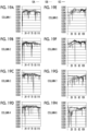
- Fig. 18 shows measurement results for Example 1
- Fig. 19 shows measurement results for the comparative example
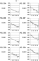
- Fig. 20 shows measurement results for Example 2.
- Figs. 18A to 18H show measurement results for respective rows 1 to 8 in the sub-scanning direction of the nozzle plates 10A, 10B, and 10C of Example 1.
- Figs. 19A to 19H are measurement results for respective columns 1 to 8 in the sub-scanning direction of the nozzle plates 10A, 10B, and 10C of the comparative examples.
- Figs. 20A to 20H are measurement results for respective rows 1 to 8 in the sub-scanning direction of the nozzle plate 10A of Example 2.
- the vertical axis indicates the nozzle opening, and the unit is mm. Further, the horizontal axis indicates the nozzle position in the main scanning direction of the nozzle plate.
- a plurality of nozzles having a significantly reduced diameter are present in any of the rows and regardless of the formation region. As described with reference to Figs. 7 to 10 , it is considered that this phenomenon of decreasing the diameter is caused by the fact that the metal layer is formed by swelling and the nozzle is partially blocked.
- Fig. 18 in the nozzle plate of Example 1, the number of nozzles having a significantly smaller diameter is extremely small as compared with the comparative example.
- Example 2 as in Example 1, the number of nozzles having a significantly smaller diameter is extremely small as compared with the comparative example.
- Examples 1 and 2 have the effect of suppressing molding defects of the openings in the case of manufacturing the metal molded product having the openings by electroforming.
- JP2020-113520A filed on June 30, 2020 is incorporated herein by reference in its entirety.
Landscapes
- Engineering & Computer Science (AREA)
- Manufacturing & Machinery (AREA)
- Chemical & Material Sciences (AREA)
- Chemical Kinetics & Catalysis (AREA)
- Electrochemistry (AREA)
- Materials Engineering (AREA)
- Metallurgy (AREA)
- Organic Chemistry (AREA)
- Particle Formation And Scattering Control In Inkjet Printers (AREA)
Abstract
Description
- The present disclosure relates to a metal molded product manufacturing method.
- There is a known metal molded product manufacturing method having a plurality of openings by using an electroforming technique (for example, refer to
JP2008-23792A JP2008-23792A -
JP2008-23792A - The nozzle plate is a thin metal plate in which a plurality of openings functioning as nozzles for ejecting ink are one-dimensionally or two-dimensionally arranged. In order to form the plurality of openings arranged in such a manner,
JP2008-23792A -
JP2002-80995A JP2002-80995A JP2002-80995 - Each of the plurality of openings of the nozzle plate described in
JP2008-23792A - In recent years, there is a demand for improvement in image quality, and the resolution of an image tends to be high. In that case, it is necessary to reduce the size of dots. Therefore, it is also necessary to reduce the size of the opening of the nozzle plate to about several tens of µm. In a case where an opening having a diameter of about several tens of µm is formed, in a case where a nozzle plate is manufactured by the method described in
JP2008-23792A JP2008-23792A - As a result of the analysis, the inventor of the present application has determined that attachment of bubbles having a diameter of several tens of µm or less to the non-conductive mask is a major cause of the molding defects of the openings. According to the analysis, the mechanism of the molding defects of the openings caused by the bubbles is presumed as follows. In a case where the bubbles are attached to the mask, the metal layer that grows so as to cover the edge portion of the mask grows while entraining the bubbles. In a case where the metal layer entrains the bubbles, the metal layer containing the bubbles is formed by swelling greater than the other parts. In such a manner, in a case where the metal layer is formed by swelling at the edge portion of the mask, the metal layer swells from the edge portion of the mask toward the central part. As the metal layer bulges toward the center of the mask, the size of the opening decreases in diameter, or the shape of the opening which should be circular is a crescent shape, which causes the molding defects of the openings.
- As described in
JP2002-80995 - However, in the case of relatively small a bubble having a diameter of several tens of µm or less, since the buoyancy is relatively small, there is a problem that, by simply tilting the substrate, the bubble cannot be sufficiently removed from the surface of the mask and the molding defect of the opening cannot be suppressed.
- The present disclosure is made in view of the above circumstances, and it is an object of the present invention to provide a metal molded product manufacturing method capable of suppressing molding defects of openings caused by bubbles having a diameter of several tens of µm or less in a case where a metal molded product having openings is manufactured by electroforming using a substrate having a mask.
- According to a first aspect of the present disclosure, there is a metal molded product manufacturing method comprising an electroforming step of growing a metal layer on a conductive surface through a metal precipitated from an electrolytic solution in a state where a substrate having a non-conductive mask formed on a part of the conductive surface is used and the substrate is immersed in the electrolytic solution and forming an opening at a position corresponding to the mask so as to manufacture a metal molded product having an opening by performing the electroforming step.
- In a case where a posture of a surface of the mask which is vertically downward and horizontal is set as a reference posture in a state where the substrate is immersed in water and the surface of the mask is tilted from the reference posture, a movement start angle, which is a tilt angle of the surface of the mask with respect to the reference posture in a case where a bubble of 3 µL attached to the surface of the mask in the reference posture starts moving along the surface of the mask due to buoyancy, is equal to or less than 20°.
- In the first aspect of the present disclosure, it is preferable that in a case where the respective movement start angles of the surface of the mask and the conductive surface are compared under the same condition, the movement start angle of the surface of the mask is smaller.
- In the first aspect of the present disclosure, it is preferable that regarding a contact angle of the bubble of 3 µL attached to the surface of the mask in the reference posture immediately before the bubble starts moving by tilting the surface of the mask from the reference posture, assuming that the contact angle on a side in a movement direction in which the bubble moves due to buoyancy is a first contact angle and the contact angle on a side opposite to the movement direction is a second contact angle, an angular difference, which is a difference between the first contact angle and the second contact angle, is equal to or less than 30°.
- According to a second aspect of the present disclosure, there is a metal molded product manufacturing method comprising an electroforming step of growing a metal layer on a conductive surface through a metal precipitated from an electrolytic solution in a state where a substrate having a non-conductive mask formed on a part of the conductive surface is used and the substrate is immersed in the electrolytic solution and forming an opening at a position corresponding to the mask so as to manufacture a metal molded product having an opening by performing the electroforming step.
- In a case where a posture of a surface of the mask which is vertically downward and horizontal is set as a reference posture in a state where the substrate is immersed in water, regarding a contact angle of the bubble of 3 µL attached to the surface of the mask in the reference posture immediately before the bubble starts moving by tilting the surface of the mask from the reference posture, assuming that the contact angle on a side in a movement direction in which the bubble moves due to buoyancy is a first contact angle and the contact angle on a side opposite to the movement direction is a second contact angle, an angular difference, which is a difference between the first contact angle and the second contact angle, is equal to or less than 30°.
- In the first and second aspects of the present disclosure, it is preferable that in a case where the respective angular differences of the surface of the mask and the conductive surface are compared under the same condition, the angular difference of the surface of the mask is smaller.
- In the first and second aspects of the present disclosure, it is preferable that a contact angle of the bubble attached to the mask in the reference posture is equal to or greater than 130°.
- It is preferable that in a case where the respective contact angles of the surface of the mask and the conductive surface in the reference posture are compared under the same condition, the contact angle of the surface of the mask is greater.
- In the first and second aspects of the present disclosure, it is preferable that a hydrophilic treatment is performed on the mask before the electroforming step.
- It is preferable that the hydrophilic treatment is a plasma treatment or an ultraviolet ozone treatment.
- In the first and second aspects of the present disclosure, a non-conductive material which is a material of the mask may be a metal oxide.
- In the first and second aspects of the present disclosure, a non-conductive material which is a material of the mask may be a photosensitive resin.
- In the first and second aspects of the present disclosure, in a case where the conductive material is a photosensitive resin, it is preferable that the metal molded product manufacturing method further comprises a mask forming step of forming a mask on the conductive surface. It is preferable that the mask forming step includes a coating step of uniformly coating the conductive surface with the photosensitive resin, an exposure step of exposing the photosensitive resin in accordance with a pattern of the mask, and a development step of developing the photosensitive resin which is exposed, and a hydrophilic treatment is performed on the photosensitive resin before the development step.
- The hydrophilic treatment may be performed after the exposure step or before the exposure step.
- In the first and second aspects of the present disclosure, it is preferable that in the electroforming step, the substrate is disposed in the electrolytic solution in a posture in which the conductive surface having the mask is vertically downward.
- It is preferable that in the posture in which the conductive surface is vertically downward, a tilt angle of the conductive surface having the mask with respect to the horizontal direction is equal to or less than 60°.
- In the first and second aspects of the present disclosure, it is preferable that the electroforming step is performed while the substrate is rotated around an axis extending in a normal direction from a center position in a plane of the conductive surface.
- In the first and second aspects of the present disclosure, it is preferable that the electroforming step is performed while the electrolytic solution is flowed in a direction in which a fluid pressure of the electrolytic solution is applied toward the conductive surface having the mask.
- In the first and second aspects of the present disclosure, the metal molded product may be a nozzle plate used for a printing head of an inkjet printer.
- Provided is a method for manufacturing a metal molded product capable of suppressing molding defects of openings due to a bubble having a diameter of 10 µm or less in a case of manufacturing a metal molded product having openings by electroforming using a substrate having a mask.
-
-
Fig. 1 is a perspective view showing an example of a metal molded product. -
Fig. 2 is a plan view showing a substrate on which a mask is formed. -
Fig. 3 is a plan view showing the entire substrate. -
Fig. 4 is a diagram showing a manufacturing step of a nozzle plate. -
Fig. 5 is a diagram showing an example of an electroforming apparatus. -
Fig. 6 is an explanatory diagram of a movement start angle of a bubble. -
Fig. 7 shows an electron microscope image showing a defect of a nozzle part on a surface of a nozzle plate. -
Fig. 8 shows an electron microscope image showing the defect of the nozzle part on the surface of the nozzle plate. -
Fig. 9 shows an electron microscope image showing a nozzle part on a rear surface of the nozzle plate. -
Fig. 10 shows an enlarged electron microscope image of the part of the rear surface of the nozzle plate shown inFig. 9 . -
Fig. 11 is an explanatory diagram for measuring a contact angle of a bubble. -
Fig. 12 is an explanatory diagram of a first contact angle and a second contact angle of the bubble. -
Fig. 13 is a diagram showing an example of a mask forming step. -
Fig. 14 is a diagram showing another example of the mask forming step. -
Fig. 15 is a graph showing a contact angle of a bubble in each film. -
Fig. 16 is a graph showing a movement start angle in each film. -
Fig. 17 is a diagram schematically showing a shape of a bubble in each film during measurement of an angular difference.Fig. 17A shows a shape of the bubble in a Ni sputter film.Fig. 17B shows a shape of a bubble on a photosensitive resin film which is not subjected to a hydrophilic treatment.Fig. 17C shows a shape of a bubble on the photosensitive resin film which is subjected to the hydrophilic treatment. -
Fig. 18 shows a measurement result of a nozzle opening diameter of a nozzle plate of Example 1. -
Fig. 19 shows a measurement result of a nozzle opening diameter of a nozzle plate of a comparative example. -
Fig. 20 shows a measurement result of a nozzle opening diameter of a nozzle plate of - Hereinafter, embodiments of the present disclosure will be described with reference to the drawings.
-
Fig. 1 is a diagram showing an example of a metal molded product manufactured by a metal molded product manufacturing method according to an embodiment. In the present example, the metal molded product is anozzle plate 10 used for a printing head of an inkjet printer. - The
nozzle plate 10 is a plate-like member having a rectangular planar shape which is formed of an electroforming metal such as nickel (Ni). Thenozzle plate 10 is formed with a plurality of substantially circular openings 12 (hereinafter, referred to as nozzles 12) that function as nozzles and are two-dimensionally arranged. Eachnozzle 12 is formed in a substantially circular shape, and a diameter D thereof is, for example, equal to or less than 100 µm, and preferably in a range of 20 µm to 50 µm. In the printing head, thenozzle plate 10 is disposed in a posture in which the long side direction corresponds to a main scanning direction X of the inkjet printer and the short side direction corresponds to a sub-scanning direction Y. A length of thenozzle plate 10 in the main scanning direction is 100 mm as an example, and a length of thenozzle plate 10 in the sub-scanning direction is 40 mm as an example. Further, in the present example, eight nozzle rows including 130nozzles 12 arranged at regular intervals in the main scanning direction X of thenozzle plate 10 are provided in the sub-scanning direction Y. - A metal molded product manufacturing method according to a first embodiment will be described. The metal molded product manufacturing method according to the first embodiment includes an electroforming step that uses a substrate in which a non-conductive mask is formed on a part of a conductive surface. In the electroforming step, in a state where the substrate is immersed in the electrolytic solution, a metal layer is grown on the conductive surface by a metal precipitated from the electrolytic solution, and an opening is formed at a position corresponding to the mask. By performing the electroforming step, a metal molded product having the opening is manufactured. In the present example, the manufacturing method of manufacturing the
nozzle plate 10 as the metal molded product will be described. -
Fig. 2 is a plan view showing a part of asubstrate 20 used as a master in a case where thenozzle plate 10 is formed by electroforming. Thesubstrate 20 has aconductive surface 20a. A metal layer to be thenozzle plate 10 grows on theconductive surface 20a of thesubstrate 20. Since thenozzle plate 10 is provided with thenozzle 12, acircular mask 25 is formed on thesubstrate 20 at a position corresponding to a nozzle forming position where thenozzles 12 are formed on theconductive surface 20a. Themask 25 is formed of a non-conductive material. Therefore, the metal does not grow in the part of themask 25 and an opening is formed, and thenozzles 12 are formed. In the present example, 130masks 25 in eight rows are formed in a region of 100 mm × 40 mm of thesubstrate 20 corresponding to an arrangement pitch and the number of thenozzles 12 of thenozzle plate 10 described above. A diameter DM of themask 25 is greater than the diameter D of thenozzle 12, and is, for example, in a range of 150 µm to 200 µm. A thickness of themask 25 is, for example, 2 µm. In the present example, themasks 25 are formed on theflat substrate 20, themasks 25 are projected with respect to theconductive surface 20a of thesubstrate 20.Fig. 3 is a plan view showing theentire substrate 20. As shown inFig. 3 , thesubstrate 20 is, for example, a disk-shaped substrate which has a diameter of 200 mm. Thesubstrate 20 includes themasks 25 of 130 pieces × 8 rows shown inFig. 2 in the nozzle plate formation regions A, B, and C which has a size of 100 mm × 40 mm. The nozzle plate formation regions A, B, and C are disposed in a three-fold rotational symmetry with a normal line that passes through acenter 20c of thesubstrate 20 as a rotational axis. That is, in thesubstrate 20, the three nozzle plate formation regions A, B, and C are disposed at intervals of 120° with the normal line as the rotational shaft. - For example, the
substrate 20 is provided with ametal film 22 on aglass wafer 21. The surface of themetal film 22 is theconductive surface 20a of thesubstrate 20. Thenon-conductive mask 25 is formed on a part of theconductive surface 20a (refer toFig. 4 ). -
Fig. 4 is a diagram showing a manufacturing step of thenozzle plate 10.Fig. 4 shows a cross unit of a part of thesubstrate 20 shown inFig. 2 including only onemask 25. First, in the provision step S0, thesubstrate 20 in which thenon-conductive mask 25 is formed on a part of theconductive surface 20a is provided. Then, in the electroforming step S1, in a state where thesubstrate 20 is immersed in the electrolytic solution, themetal layer 11 is grown on theconductive surface 20a by the metal precipitated from the electrolytic solution. - During electroforming, the
metal layer 11 grows on theconductive surface 20a, whereas no metal is precipitated on the surface of thenon-conductive mask 25, and themetal layer 11 does not grow. Themetal layer 11 gradually grows on theconductive surface 20a. Thereafter, in a case where a thickness of the grownmetal layer 11 is greater than a thickness of themask 25, themetal layer 11 grows on thenon-conductive mask 25 side from the surface of the previously grownmetal layer 11 so as to cover the edge portion of themask 25. As themetal layer 11 grows from the edge portion of themask 25 toward the center, an opening is formed in themetal layer 11 with the opening center at a substantially center position of themask 25. The opening is thenozzle 12. As the thickness of themetal layer 11 increases, themetal layer 11 grows toward the center of themask 25. Therefore, the opening diameter of thenozzle 12 also gradually decreases. The diameter of themask 25 is determined such that thenozzle 12 has a desired opening diameter in a case where themetal layer 11 is grown to have a desired thickness. The growth of themetal layer 11 on themask 25 is larger at a position closer to theconductive surface 20a. Therefore, as shown inFig. 4 , the opening diameter of thenozzle 12 is smaller at a position closer to theconductive surface 20a and is larger at a position away from theconductive surface 20a. The cross unit of themetal layer 11 forming an inner wall surface of thenozzle 12 is arc-shaped. For example, as a reference of a target opening diameter of thenozzle 12, the opening diameter of thenozzle 12 close to theconductive surface 20a is set. Then, the diameter of themask 25 is determined such that the opening diameter of thereference nozzle 12 is the target opening diameter. The thickness t of themetal layer 11 is, for example, about 50 µm. - After the electroforming step, the
metal layer 11 is peeled off from the substrate 20 (peeling step S2). In such a case, themask 25 is peeled off from thesubstrate 20 together with themetal layer 11. - Thereafter, the
mask 25 is removed (mask removal step S3). Thereby, it is possible to obtain thenozzle plate 10. - The electroforming step S1 will be described in detail.
Fig. 5 shows an example of theelectroforming apparatus 30 used in the electroforming step S1. Theelectroforming apparatus 30 comprises anelectroforming tank 32, asubstrate holding mechanism 35, ananode 39, and acirculation mechanism 40 of anelectrolytic solution 34. - The
electroforming tank 32 stores theelectrolytic solution 34. Theanode 39 is disposed on a part of the inner wall surface of theelectroforming tank 32. During electroforming, thesubstrate 20 is immersed in theelectrolytic solution 34 of theelectroforming tank 32. Thesubstrate 20 is disposed in theelectrolytic solution 34, in a posture in which theconductive surface 20a faces theanode 39. Theanode 39 is configured to include an electroforming metal such as nickel pellets and has a size by which theanode 39 is capable of facing the entire region of theconductive surface 20a on thesubstrate 20. Electroforming is performed on thesubstrate 20 in a state where theconductive surface 20a of thesubstrate 20 faces theanode 39. - In the present example, a part of the side wall of the
electroforming tank 32 is tilted. The tilt direction of the side wall is a direction in which the upper opening becomes wider than the opening on the bottom surface of theelectroforming tank 32 due to the tilt of the side wall. The tilt angle of the side wall is, for example, in a range of about 40° to about 50° with respect to the horizontal direction. Theanode 39 is disposed along the inner wall surface of the tilted side wall in a tilted posture with respect to the horizontal direction. - The
substrate holding mechanism 35 includes a holdingpart 36, arotational shaft 37, and arotation device 38. The holdingpart 36 holds thesubstrate 20 from the opposite surface side of theconductive surface 20a of thesubstrate 20. Therotational shaft 37 is attached to the rear surface of the holdingpart 36 and extends in the normal direction of the rear surface of the holdingpart 36. Therotation device 38 rotates the holdingpart 36 through therotational shaft 37. The holdingpart 36 holds thesubstrate 20 in theelectroforming tank 32 such that theconductive surface 20a of thesubstrate 20 faces theanode 39. That is, in thesubstrate 20, theconductive surface 20a is disposed in a vertically downward posture. Here, the vertically downward posture means a posture in which the tilt angle of theconductive surface 20a with respect to the horizontal direction is equal to or greater than 0° and less than 90°. In the present example, the tilt angle is greater than 0°, and theconductive surface 20a is disposed in a posture in which theconductive surface 20a is horizontally tilted. - The holding
part 36 holds thesubstrate 20 by such that the center coincides with therotational shaft 37. In a case where therotation device 38 is driven, thesubstrate 20 rotates integrally with the holdingpart 36 through therotational shaft 37, with the center coinciding with therotational shaft 37 as the center of rotation. Thesubstrate 20 is set in the holdingpart 36 outside theelectroforming tank 32, and is immersed in theelectroforming tank 32 in a state of being held by the holdingpart 36. Then, electroforming is performed while thesubstrate 20 is rotated about an axis extending in the normal direction from a center position in the plane of theconductive surface 20a. - During electroforming, the
conductive surface 20a of thesubstrate 20 is used as a cathode, and theconductive surface 20a serving as a cathode and theanode 39 including the electroforming metal are energized. Thereby, the electroforming metal of theanode 39 is electrolyzed and is dissolved in theelectrolytic solution 34 as electric ions. Then, themetal layer 11 is formed by electrodepositing the metal precipitated from theelectrolytic solution 34 on theconductive surface 20a serving as a cathode. - The
circulation mechanism 40 includes areservoir 41, adischarge pipe 42, avalve 43, apump 44, afilter 46, asupply pipe 47, and anozzle 48. Thecirculation mechanism 40 circulates theelectrolytic solution 34 stored in theelectroforming tank 32 between theelectroforming tank 32 and thereservoir 41 disposed outside theelectroforming tank 32. Through the circulation, theelectrolytic solution 34 is made to flow between theconductive surface 20a and theanode 39. - The
discharge pipe 42 and thesupply pipe 47 form a circulation passage for theelectrolytic solution 34 between theelectroforming tank 32 and thereservoir 41. Thedischarge pipe 42 constitutes a returning pipe line in which theelectrolytic solution 34 in theelectroforming tank 32 is discharged and the dischargedelectrolytic solution 34 is returned to thereservoir 41 through the circulation passage. Thesupply pipe 47 constitutes a supply pipe line for supplying theelectrolytic solution 34 from thereservoir 41 to theelectroforming tank 32 in the circulation passage. - One end of the
discharge pipe 42 is disposed in theelectroforming tank 32, and the other end thereof is connected to thereservoir 41. Through thedischarge pipe 42, theelectrolytic solution 34, which has an amount greater than a preset specified amount in theelectroforming tank 32, is returned to thereservoir 41. Therefore, one end of thedischarge pipe 42 is disposed at substantially the same height as the liquid surface of the specified amount of theelectrolytic solution 34 with the opening facing upward. Thereby, theelectrolytic solution 34 in excess of the specified amount in theelectroforming tank 32 flows into thedischarge pipe 42 and is returned to thereservoir 41 through thedischarge pipe 42. - One end of the
supply pipe 47 is also disposed in theelectroforming tank 32, and the other end thereof is connected to thereservoir 41. Thenozzle 48, through which theelectrolytic solution 34 is injected into theelectroforming tank 32, is connected to one end of thesupply pipe 47. The other end of thesupply pipe 47 is connected to the lower part of thereservoir 41. Thevalve 43, thepump 44, and thefilter 46 are disposed on the supply pipe line constituted of thesupply pipe 47 in order from thereservoir 41 side which is the upstream side of theelectrolytic solution 34 in the supply direction. Thevalve 43 opens and closes a supply passage. In a case where the supply passage is opened through thevalve 43 in a state where thepump 44 is driven, the supply of theelectrolytic solution 34 from thereservoir 41 to theelectroforming tank 32 is started. Thefilter 46 filters theelectrolytic solution 34. Theelectrolytic solution 34 that passes through thefilter 46 is supplied into theelectroforming tank 32 through thesupply pipe 47. Through thenozzle 48, theelectrolytic solution 34 is injected toward between theconductive surface 20a of thesubstrate 20 and theanode 39. - As described above, in the
electroforming step S 1, theelectrolytic solution 34 is circulated between theelectroforming tank 32 and thereservoir 41 by using thecirculation mechanism 40. Then, in theelectroforming tank 32, theelectrolytic solution 34 is injected from thenozzle 48 toward between theconductive surface 20a and theanode 39. Thereby, theelectrolytic solution 34 is flowed in a direction in which the fluid pressure of theelectrolytic solution 34 is applied toward theconductive surface 20a having themask 25. Theelectroforming step S 1 is performed while theelectrolytic solution 34 is flowed in such a manner. - As described above, the electroforming is performed on the
conductive surface 20a of the substrate. - In the present embodiment, as the
substrate 20 on which thenon-conductive mask 25 is formed, a substrate in which a movement start angle of a bubble attached to the surface of themask 25 is equal to or less than 20° is used. The movement start angle is one of indicators indicating the surface characteristics of themask 25, and is defined herein as follows. The movement start angle is a tilt angle of the surface of themask 25 with respect to the reference posture in a case where a bubble of 3 microliters (µL) attached to themask 25 starts moving along the surface of themask 25 due to buoyancy, in a case where a surface of themask 25 is vertically downward and a horizontal posture is set as a reference posture in a state where thesubstrate 20 is immersed in water and the surface of themask 25 is tilted from the reference posture. The surface of themask 25 is parallel with theconductive surface 20a of thesubstrate 20 on which themask 25 is formed. Therefore, the above-mentioned reference posture is obtained in a case where thesubstrate 20 is disposed such that theconductive surface 20a is vertically downward and is in a horizontal posture. - Here, the movement start angle will be specifically described with reference to
Fig. 6 . - As shown in the upper part of
Fig. 6 , a base material S, which is a parallel plate having two main surfaces s1 and s2 parallel to each other, is disposed in water such that one main surface s1 is vertically downward and is horizontal. Specifically, first, a fixingbase 54 for fixing the base material S is immersed in water, and the fixingbase 54 is provided such that a fixingsurface 54a of the fixingbase 54 is horizontal in water. The fixingbase 54 is disposed such that the other main surface s2 of the base material S comes into contact with the fixingsurface 54a. Thereby, the base material S is disposed in the reference posture. Next, in the reference posture, the main surfaces s1 and s2 of the base material S are horizontal planes. Thebubble 50 of 3 µL is brought into contact with the main surface s1 of the base material S. A dispensing nozzle (not shown in the drawing) is disposed below the main surface s1 of the base material S, and air of 3 µL is discharged toward the base material S. Thereby, thebubble 50 of 3 µL is generated, and the generatedbubble 50 is brought into contact with the main surface s1 of the base material S. - After the
bubble 50 is attached to the main surface s1, the base material S is gradually tilted together with the fixingbase 54 and the fixingsurface 54a from the reference posture shown in the upper part ofFig. 6 . In such a case, the angle formed by the fixingsurface 54a in a case where thebubble 50 starts moving along the main surface s1 of the base material S in the horizontal direction is measured. The main surface s1 of the base material S is parallel with the fixingsurface 54a. Therefore, the measured angle of the fixingsurface 54a is an angle of the main surface s1 of the base material S, and corresponds to the movement start angle in a case where thebubble 50 starts moving along the main surface s1. Specifically, using a camera of a contact angle measurement device, a state in which the base material S is gradually tilted together with the fixingbase 54 is captured from the horizontal direction. Then, an angle formed between the fixingsurface 54a and the horizontal direction is obtained through image analysis from an image in a case where thebubble 50 starts moving along the main surface s1 of the base material S. - The measurement of the angle formed between the fixing
surface 54a and the horizontal direction in a case where thebubble 50 starts moving along the main surface s1 is performed, for example, at least three times, and an average value thereof is set as the movement start angle θ of the bubble with respect to the base material. The water used for the measurement is distilled water, and the bubble is an air bubble. By replacing the surface of the base material S with themask 25, the movement start angle θ of the bubble with respect to the surface of themask 25 can be obtained in a similar manner. - As described above, the movement start angle θ at which the bubble moves from the surface of the
mask 25 is one of the indicators indicating the surface characteristics of themask 25, and is used as an indication that thebubble 50 is likely to remain on the surface of themask 25. A larger movement start angle θ means that thebubble 50 is more likely to remain on the surface of themask 25, and a smaller movement start angle θ means that thebubble 50 is less likely to remain on the surface of themask 25. In a case where the movement start angle θ of the bubble of 3 µL is equal to or less than 20°, attachability of thebubble 50 to the surface of themask 25 is low. Therefore, thebubble 50 is likely to move. Thebubble 50 of 3 µL corresponds to aspherical bubble 50 having a diameter of 4.6 mm. As the size of thebubble 50 is smaller, the buoyancy is smaller. Therefore, thebubble 50 tends to be less likely to move. According to the study by the inventors of the present disclosure, regarding the surface of themask 25 in which the movement start angle θ of thebubble 50 of 3 µL is equal to or less than 20°, it is presumed that there is the following effect. Even aminute bubble 50 having a diameter of several tens of µm or less is likely to move, and attachment of theminute bubble 50 to the surface of themask 25 is suppressed. Further, although the movement start angle θ in water is specified herein, there is a correlation between the movement start angle θ of thebubble 50 in water and the movement start angle θ of thebubble 50 in the electrolytic solution during electroforming. That is, the movement start angle θ in the electrolytic solution is also large in a case where the movement start angle θ in water is large, and the movement start angle θ in the electrolytic solution is also large in a case where the movement start angle θ in water is large. According to the study by the inventors of the present disclosure, it is presumed that there is the following effect. In a case where the movement start angle θ of thebubble 50 of 3 µL on the surface of themask 25 in water is equal to or less than 20°, it is possible to suppress remaining of thebubble 50 and attachment of theminute bubble 50 having a diameter of several tens of µm or less on the surface of thesame mask 25 in the electrolytic solution during electroforming. - Here,
Figs. 7 to 10 show electron beam microscope images showing states of the molding defects of thenozzle 120 in a case where a nozzle plate having thenozzle 120 for an inkjet printer is manufactured by electroforming by a conventional method.Fig. 7 shows an image obtained by observing thenozzle 120 from the front on the growth surface side, andFig. 8 shows an image obtained by observing thenozzle 120 shown inFig. 7 from an oblique direction. Originally, thenozzle 120 should have a circular opening shape, but thenozzle 120 in which the molding defect has occurred has a crescentic opening shape as shown inFigs. 7 and 8 . InFigs. 7 and 8 , a part that appears black is thenozzle 120. The reason why thenozzle 120 has a crescent shape is that a part of themetal layer 11 that grows so as to cover the edge portion of themask 25 is abnormally swelled as compared with the other part thereof.Fig. 9 shows an image obtained by observing thenozzle 120 shown inFig. 7 and Fig. 8 from the opposite surface side. InFig. 9 , it is more clearly shown that the opening shape of thenozzle 120 is the crescent shape. Further, inFig. 9 , a region in the white frame defined by the circular white frame surrounding thenozzle 120 having a crescent shape is a region corresponding to the shape of thecircular mask 25. In the region, the surface is recessed by a thickness of themask 25 from the surface around the region. - Further, in
Fig. 9 , in the circular region within the white frame, thehole 121 is formed in the vicinity of thenozzle 120 having a crescent shape. Ahole 121 is located at a position corresponding to a part where the metal layer is raised on the growth surface side of themetal layer 11.Fig. 10 shows an enlarged image of thehole 121. As shown inFig. 10 , thehole 121 is formed by a cavity formed inside themetal layer 11. That is, as shown inFigs. 7 and 8 , it is considered that the abnormally bulging part observed on the growth surface side of themetal layer 11 is caused by formation of a cavity inside. Then, it is presumed that the opening part of the cavity is thehole 121 shown inFigs. 9 and 10 . Further, it is considered that the cause of the cavity in themetal layer 11 is thebubble 50 attached to the edge portion of themask 25. That is, since electroforming is performed in a state where thebubble 50 is attached, thebubble 50 is entrained and themetal layer 11 grows. As a result, a cavity is formed in themetal layer 11, and it is considered that the cavity causes an abnormal swelling of themetal layer 11. - That is, in a case in which the
bubble 50 is not attached to themask 25, the molding defect of thenozzle 12 can be suppressed. As described above, as thesubstrate 20 on which thenon-conductive mask 25 is formed, thesubstrate 20 having the following configuration is used. In a case where a posture of a surface of themask 25 which is vertically downward and horizontal is set as a reference posture in a state where thesubstrate 20 is immersed in water and the surface of themask 25 is tilted from the reference posture, a movement start angle, which is a tilt angle of the surface of themask 25 with respect to the reference posture in a case where the bubble of 3 µL attached to themask 25 starts moving along the surface of themask 25 due to buoyancy, is equal to or less than 20°. Since such asubstrate 20 is used, the bubble can be easily removed from the surface of themask 25 as compared with the conventional case. Therefore, the molding defect of the nozzle 12 (an example of the opening of metal molded product) of thenozzle plate 10, which is an example of a metal molded product, can be reduced. In particular, even a minute bubble having a diameter of several tens of µm or less can be easily removed. Therefore, in a case of manufacturing the metal molded product having the nozzles 12 (an example of openings of the metal molded product) of 100 µm or less, such as thenozzle plate 10, there is a high effect of suppressing molding defects of the openings. - In a case where the movement start angles θ of the surface of the
mask 25 and theconductive surface 20a are compared under the same condition, it is preferable to use thesubstrate 20 in which the movement start angle θ of the surface of themask 25 is smaller. - By making the movement start angle of the surface of the
mask 25 smaller than that of theconductive surface 20a, as compared with a case where the movement start angles of the surface of themask 25 and theconductive surface 20a are the same, thebubble 50 is likely to move from the surface of themask 25 toward theconductive surface 20a. Therefore, it is possible to more reliably reduce molding defects of openings. - The
substrate 20 of the present example has the following configuration. Theconductive surface 20a is a flat surface, and themask 25 is formed on the flatconductive surface 20a. As a result, themask 25 is disposed to be projected with respect to theconductive surface 20a. However, themask 25 may be formed at a position lower by one stage than theconductive surface 20a of thesubstrate 20, and a portion where themask 25 is formed may be recessed. Further, the heights of theconductive surface 20a and the surface of themask 25 may be the same, and both surfaces may be coplanar. - Next, a metal molded product manufacturing method according to a second embodiment will be described. In a similar manner to the first embodiment, the metal molded product manufacturing method according to the second embodiment also includes an electroforming step of using the
substrate 20 in which thenon-conductive mask 25 is formed on a part of theconductive surface 20a. In the electroforming step, in a state where thesubstrate 20 is immersed in theelectrolytic solution 34, themetal layer 11 is grown on theconductive surface 20a by the metal precipitated from theelectrolytic solution 34, and the opening is manufactured at a position corresponding to themask 25. In the present example as well, a manufacturing method of manufacturing thenozzle plate 10 as the metal molded product will be described. The entire flow of the manufacturing step shown inFig. 4 is basically the same as that of the first embodiment described above. In the following description, only the differences will be described, and detailed description of the same parts will be omitted. - In the present embodiment, as the
substrate 20 on which thenon-conductive mask 25 is formed, thesubstrate 20 that satisfies the following conditions as the condition about the contact angle of thebubble 50 with respect to themask 25 is used. First, the contact angle of thebubble 50 is defined as follows. That is, in a case where a posture of a surface of themask 25 which is vertically downward and horizontal is set as a reference posture in a state where thesubstrate 20 is immersed in water, regarding a contact angle of thebubble 50 immediately before thebubble 50 of 3 µL attached to the surface of themask 25 in the reference posture starts moving by tilting the surface of themask 25 from the reference posture, it is assumed that the contact angle on a side in a movement direction in which thebubble 50 moves due to buoyancy is a first contact angle ϕ1 and the contact angle on a side opposite to the movement direction is a second contact angle ϕ2. In such a case, as thesubstrate 20, thesubstrate 20 in which an angular difference Δϕ = ϕ2-ϕ1 which is the difference between the first contact angle ϕ1 and the second contact angle ϕ2 is equal to or less than 30° is used. - Here, the contact angle ϕ, the first contact angle ϕ1, and the second contact angle ϕ2 of the
bubble 50 will be described with reference toFigs. 11 and12 . - First, a measuring method of the contact angle ϕ of the
bubble 50 will be described. As shown inFig. 11 , first, the base material S, which is a parallel plate having two main surfaces s1 and s2 parallel to each other, is disposed in water in a water tank, in whichwater 52 is stored, such that one main surface s1 is vertically downward and horizontal. Specifically, the fixing base 54 (not shown inFig. 11 ) shown inFig. 6 is used and is disposed such that the other main surface s2 of the base material S comes into contact with the fixingsurface 54a. Thereby, the base material S is disposed in the reference posture. Next, in the reference posture, the main surfaces s1 and s2 of the base material S are horizontal planes. Thebubble 50 of 3 µL is brought into contact with the main surface s1 of the base material S. - The contact angle ϕ of the
bubble 50 means an angle between the base material S and the tangent line of thebubble 50 at the end part where thebubble 50 is in contact with the base material S in a case where thebubble 50 being in contact with the base material S is observed from the horizontal direction. Specifically, a camera of a contact angle measurement device is used to image the horizontally disposed base material S and thebubble 50 being in contact with the surface of the base material S from the horizontal direction. Thereby, the angle formed between the tangent line of thebubble 50 and the base material S is obtained through the image analysis. The measurement is performed, for example, at least three times, and an average value thereof is set as the contact angle ϕ. By replacing the surface of the base material S with themask 25, the contact angle ϕ of the bubble with respect to the surface of themask 25 can be obtained in a similar manner. - Next, the first contact angle ϕ1 and the second contact angle ϕ2 will be described. As shown in
Fig. 12 , the first contact angle ϕ1 is a contact angle on a side of the movement direction in which thebubble 50 moves at the above-mentioned movement start angle θ (refer toFig. 6 ), and the contact angle is also referred to as a forward contact angle. Further, the second contact angle ϕ2 is a contact angle on a side opposite to the movement direction in which the bubble moves immediately before the movement start angle, and the contact angle is also referred to as a backward contact angle. In a similar manner to the case of the movement start angle θ shown inFig. 6 , thebubble 50 of 3 µL is attached to the surface of the base material S, and together with the fixingbase 54, the base material S is tilted from the reference posture (not shown inFig. 12 , refer toFig. 6 ), in a direction in which an angle formed between the fixingsurface 54a and the horizontal plane increases. In such a case, the contact angle of thebubble 50 is measured in a case where the tilt angle of the main surface s1 of the base material S with respect to the horizontal direction is the movement start angle θ, that is, immediately before thebubble 50 starts moving. Specifically, using a camera of a contact angle measurement device, a state in which the base material S is gradually tilted together with the fixingbase 54 is imaged from a horizontal direction, and an angle, which is formed between the base material S and the tangent line at the end part on the side of the movement direction of the bubble in an image immediately before thebubble 50 leave the base material S, and an angle, which is formed between the base material S and the tangent line at the end part on the side opposite to the movement direction of thebubble 50 are obtained through the image analysis. - The measurement is performed at least three times for each angle, and the average values thereof are set as the first contact angle ϕ1 and the second contact angle ϕ2, respectively. The angular difference Δcp between the first contact angle ϕ1 and the second contact angle ϕ2 obtained in such a manner is obtained.
- The angular difference Δϕ between the first contact angle ϕ1 and the second contact angle ϕ2 at the movement start angle at which the
bubble 50 moves from the surface of themask 25 is one of the indicators indicating the surface characteristics of themask 25, and is used as an indication that thebubble 50 is likely to remain on the surface of themask 25. - The angular difference Δϕ between the first contact angle ϕ1 and the second contact angle ϕ2 indicates asymmetry between the
bubble 50 on the side of the movement direction and the side opposite to the movement direction. The smaller the asymmetry immediately before the start of movement, the more thebubble 50 is likely to move, and the larger the asymmetry, the less thebubble 50 is likely to move. That is, the larger the angular difference Δϕ, which is the difference between the first contact angle ϕ1 and the second contact angle ϕ2, the more thebubble 50 is likely to remain on the surface of themask 25, and the smaller the angular difference Δϕ, the less thebubble 50 is likely to remain on the surface of themask 25. In a case where the angular difference Δcp is equal to or less than 30°, the attachability of thebubble 50 to the surface of themask 25 is weak. Therefore, thebubble 50 is likely to move. As the size of thebubble 50 is smaller, the buoyancy is smaller. Therefore, thebubble 50 tends to be less likely to move. According to the study by the inventors of the present disclosure, regarding the surface in which the angular difference of the bubble of 3 µL is equal to or less than 30°, there is the following effect. Even aminute bubble 50 having a diameter of several tens of µm or less is likely to move, and attachment of the minute bubble to the surface of the mask is suppressed. - Further, although the angular difference of the
bubble 50 immediately before thebubble 50 starts moving from the surface of themask 25 in water is defined herein, there is a correlation between the angular difference in water and the angular difference in the electrolytic solution during electroforming. That is, in a case where the angular difference in water is large, the angular difference in the electrolytic solution is large, and in a case where the angular difference in water is large, the angular difference in the electrolytic solution is also large. According to the study by the inventors of the present disclosure, there is the following effect. In a case where the angular difference immediately before the start of movement of the bubble of 3 µL on the surface of themask 25 in water is equal to or less than 30°, it is possible to suppress remaining of the bubble and attachment of the minute bubble having a diameter of several tens of µm or less on the surface of thesame mask 25 in the electrolytic solution during electroforming. - In a case where the bubble is not attached to the
mask 25, the molding defect of the nozzle is suppressed. As described above, as thesubstrate 20 on which thenon-conductive mask 25 is formed, thesubstrate 20 having the following configuration is used. In a case where a posture in which the surface of themask 25 is vertically downward and is horizontal is set as a reference posture in a state where thesubstrate 20 is immersed in water, the angular difference Δcp between the first contact angle ϕ1 and the second contact angle ϕ2 of thebubble 50 immediately before thebubble 50 of 3 µL attached to the surface of themask 25 starts moving by tilting the surface of themask 25 from the reference posture is equal to or less than 30°. Since such asubstrate 20 is used, bubbles can be easily removed from the surface of themask 25 as compared with the conventional case. Therefore, it is possible to reduce molding defects of the openings of the metal molded product. In particular, since it is easy to remove even minute bubble having a diameter of several tens of µm or less, there is a high effect of suppressing molding defects of the openings in the metal molded product having openings of 100 µm or less, such as the nozzle plate. - In a case where the respective angular differences Δcp of the surface of the
mask 25 and theconductive surface 20a are compared under the same condition, it is preferable to use thesubstrate 20 in which the angular difference Δcp of the surface of themask 25 is smaller. - By making the angular difference of the surface of the
mask 25 smaller than that of theconductive surface 20a, as compared with a case where the angular differences Δcp of the surface of themask 25 and theconductive surface 20a are the same, thebubble 50 is likely to move from the surface of themask 25 toward theconductive surface 20a. Therefore, it is possible to more reliably reduce molding defect of the opening. - As described above, in the first embodiment, as the
substrate 20, thesubstrate 20 in which the movement start angle θ of thebubble 50 on the surface of themask 25 is equal to or less than 20° is used as the surface characteristic of themask 25. Further, as described above, the second embodiment is an embodiment which uses thesubstrate 20 of which the angular difference Δcp which is a difference between the first contact angle ϕ1 and the second contact angle ϕ2 of the bubble on the surface of themask 25 as the surface characteristic of themask 25 is equal to or less than 30°. Furthermore, as thesubstrate 20 on which thenon-conductive mask 25 is formed, it is preferable to use thesubstrate 20 having the surface characteristics of each of themasks 25 of the first and second embodiments. That is, the posture of the surface of themask 25 is vertically downward and horizontal is set as the reference posture in a state where thesubstrate 20 is immersed in water, and the surface of themask 25 is tilted from the reference posture. In such a case, it is preferable to use thesubstrate 20 having the following configuration. The movement start angle is equal to or less than 20°, which is a tilt angle with respect to the reference posture of the surface of themask 25 in a case where the bubble of 3 microliters (µL) attached to the surface of themask 25 starts moving along the surface of themask 25 due to buoyancy. In addition, regarding the contact angle of the bubble immediately before the bubble of 3 µL attached to the surface of themask 25 in the reference posture starts moving by tilting the surface of themask 25 from the reference posture, assuming that the contact angle on the side of the movement direction in which the bubble moves due to the buoyancy is the first contact angle and the contact angle on the side opposite to the movement direction is the second contact angle, the angular difference is 30°, which is a difference between the first contact angle and the second contact angle. By using such thesubstrate 20, it is possible to more effectively suppress attachment of the bubble on themask 25, and thus it is possible to more effectively suppress the molding defect of thenozzle 12. - In each embodiment, it is preferable to use a substrate in which the contact angle ϕ of the
bubble 50 attached to themask 25 in the reference posture is equal to or greater than 130°. It is more preferable that the contact angle ϕ of the bubble attached to themask 25 in the reference posture is equal to or greater than 130°. - The larger the contact angle of the
bubble 50, the more the bubble on the surface of themask 25 is likely to move, and the smaller the contact angle of thebubble 50, the more the bubble is likely to remain on the surface of themask 25. In a case where the contact angle ϕ of thebubble 50 is equal to or greater than 130°, the attachment force of thebubble 50 to the surface of themask 25 is weak. Therefore, thebubble 50 is likely to move. According to the study by the inventors of the present disclosure, regarding the surface in which the contact angle ϕ of thebubble 50 is equal to or greater than 130°, the following effect is further improved. Even aminute bubble 50 having a diameter of several tens of µm or less is likely to move, and attachment of theminute bubble 50 to the surface of themask 25 is suppressed. Further, although the contact angle of thebubble 50 in water is defined herein, there is a correlation between the contact angle of thebubble 50 in water and the contact angle of thebubble 50 in the electrolytic solution during electroforming. That is, in a case where the contact angles of the bubbles in water are large, the contact angles of the bubbles in the electrolytic solution are also large, and in a case where the contact angles of the bubbles in water are large, the contact angles of the bubbles in the electrolytic solution are also large. According to the study by the inventors of the present disclosure, in a case where the contact angle of thebubble 50 of 3 µL attached to themask 25 in the reference posture is equal to or greater than 130°, it is possible to suppress the remaining of thebubble 50 on the surface of thesame mask 25 in the electrolytic solution during electroforming. As a result, there is an effect of suppressing attachment of the minute bubble having a diameter of several tens of µm or less. - In a case where the
bubble 50 is not attached to themask 25, the molding defect of thenozzle 12 can be suppressed. In the first or second embodiment, as thesubstrate 20 on which thenon-conductive mask 25 is formed, thesubstrate 20 in which the contact angle ϕ of thebubble 50 attached to themask 25 in the reference posture is equal to or greater than 130° is used. Thereby, since thebubble 50 is further easily removed from the surface of the mask, it is possible to further reduce molding defects of openings of the metal molded product. In particular, since it is easy to remove even theminute bubble 50 having a diameter of several tens of µm or less, the effect of suppressing the molding defect of the opening is further enhanced in the metal molded product having an opening of 100 µm or less, such as thenozzle plate 10. - In a case where the surface of the
mask 25 is hydrophilic, the contact angle of thebubble 50 with respect to the surface of themask 25 in water is large. Further, in a case where the surface of themask 25 is hydrophobic, the contact angle of thebubble 50 with respect to the mask surface in water is small. That is, the more hydrophilic the surface of themask 25 is, the larger the contact angle of thebubble 50 is, and the higher the effect of suppressing the attachment of thebubble 50 is. - Regarding the respective contact angles ϕ of the
bubble 50 on the surface of themask 25 and theconductive surface 20a of thesubstrate 20, in a case where the contact angles thereof in the reference posture are compared under the same condition, it is preferable to use thesubstrate 20 of which the contact angle ϕ is larger on the surface of themask 25. - By making the contact angle ϕ of the
bubble 50 on the surface of themask 25 smaller than that of theconductive surface 20a, as compared with a case where the contact angles ϕ of the surface of themask 25 and theconductive surface 20a are the same, thebubble 50 is likely to move from the surface of themask 25 toward theconductive surface 20a. Therefore, it is possible to more reliably reduce molding defects of openings in the metal molded product. - In a case where the
electroforming apparatus 30 shown inFig. 5 described above is used, thesubstrate 20 is disposed in the electrolytic solution in a posture in which theconductive surface 20a is vertically downward. However, thesubstrate 20 may be disposed in a posture in which theconductive surface 20a is vertically upward. In a case where theconductive surface 20a is vertically upward, thebubble 50 is not pressed by thesubstrate 20. Therefore, thebubble 50 is likely to move due to buoyancy as compared with a case where theconductive surface 20a is vertically downward. Therefore, bubbles on the surface of the mask can be reduced more reliably. On the other hand, in a case where theconductive surface 20a is disposed to be vertically downward, a pressing force is applied by thesubstrate 20 to thebubble 50. Therefore, thebubble 50 is less likely to move as compared with a case where theconductive surface 20a is vertically upward. However, by using thesubstrate 20 described in the above-mentioned embodiment, even in a case where theconductive surface 20a is disposed to be vertically downward, attachment of a bubble to the surface of themask 25 can be suppressed. As a result, it is possible to reduce molding defects of openings in the metal molded product. Further, by setting theconductive surface 20a in the vertically downward posture, it is possible to suppress foreign matter in the electrolytic solution falling from above in the vertical direction from being attached to the conductive surface as compared with a case of the vertically upward posture. - In the vertically downward posture, it is preferable that the tilt angle of the conductive surface having the
mask 25 with respect to the horizontal direction is equal to or less than 60°. Attachment of foreign matter onto the conductive surface can be more reliably suppressed. - In the electroforming step of the metal molded product manufacturing method according to the above-mentioned embodiment, the electroforming is performed while the
substrate 20 is rotated about an axis extending in the normal direction from the center position in the plane of the conductive surface by using the electroforming apparatus shown inFig. 5 . However, the electroforming may be performed while thesubstrate 20 is held at a fixed position without rotating thesubstrate 20. - However, by performing the electroforming step while rotating the
substrate 20, it is possible to form the metal layer under electroforming conditions which are identical over the entire region without making the electroforming conditions different at the positions of thesubstrate 20. In particular, as shown inFig. 3 , in a case where a plurality of nozzle plate formation regions A, B, and C are provided in onesubstrate 20, individual differences between metal molded products are suppressed, and it is possible to manufacture the equivalent metal molded products. - The electroforming step of the metal molded product manufacturing method according to the above-mentioned embodiment is performed while the electrolytic solution is flowed in a direction in which the fluid pressure of the
electrolytic solution 34 is applied toward theconductive surface 20a of thesubstrate 20. However, the electroforming step may be performed without causing the flow. However, by performing the electroforming step while flowing the electrolytic solution in a direction in which the fluid pressure of the electrolytic solution is applied toward theconductive surface 20a, attachment of foreign matter onto the surface of themask 25 and theconductive surface 20a can be suppressed. Further, an effect of removing thebubble 50 remaining on the surface of themask 25 can also be obtained. By suppressing the attachment of foreign matter to theconductive surface 20a, it is possible to obtain the metal molded product in which defects are suppressed. Further, by attachment of foreign matter onto the surface of themask 25 and removal of thebubble 50 from the surface of themask 25, it is possible to obtain the metal molded product in which the opening defects are suppressed. - Next, the
substrate 20 in which thenon-conductive mask 25 is formed on a part of theconductive surface 20a will be described in detail. - As the
substrate 20 which has theconductive surface 20a, for example, as described in the above-mentioned embodiment, thesubstrate 20 may have a configuration in which themetal film 22 is provided on one surface of theglass wafer 21. Thesubstrate 20 can be obtained by forming themetal film 22 such as nickel or copper on theglass wafer 21 through sputtering, vacuum vapor deposition, or the like. Further, the metal substrate may be used as thesubstrate 20 having theconductive surface 20a. In a case of a metal substrate, it is not necessary to separately form the metal film by sputtering or the like. - The non-conductive material which is a material of the
non-conductive mask 25 may be a metal oxide or a photosensitive resin. - In a case where the metal oxide is used as the non-conductive material, a vapor deposition mask having openings having a desired mask shape is disposed on the
substrate 20 so as to face theconductive surface 20a of thesubstrate 20, and vacuum vapor deposition is performed. Thereby, it is possible to form themask 25. Examples of the metal oxide include silicon oxide. In a case where the metal oxide is used as themask 25, themask 25 remains on the substrate side at the time of peeling the metal layer in the peeling step described in the metal molded product manufacturing method according to the above-mentioned embodiment. Therefore, the substrate in which thenon-conductive mask 25 is formed on a part of the conductive surface can be repeatedly used a plurality of times. - It is preferable that the
non-conductive mask 25 is subjected to the hydrophilic treatment before the electroforming step. By performing the hydrophilic treatment, the movement start angle θ can be set to be equal to or less than 20°, which is the tilt angle with respect to the reference posture of the surface of themask 25 in a case where thebubble 50 of 3 µL attached to the surface of themask 25 starts moving along the surface of themask 25 due to buoyancy. Alternatively, by performing the hydrophilic treatment, the angular difference Δϕ can be set to be equal to or less than 30°, which is a difference between the first contact angle ϕ1 and the second contact angle ϕ2 of the bubble immediately before the bubble of 3 µL starts moving by tilting the surface of themask 25 from the reference posture. Further, the movement start angle θ, which is a tilt angle with respect to a reference posture of the surface of themask 25 in a case wherebubble 50 of 3 µL attached to the surface of themask 25 starts moving along the surface of themask 25 due to buoyancy, is equal to or less than 20°. In addition, by performing the hydrophilic treatment, the angular difference Δcp can be set to be equal to or less than 30°, which is a difference between the first contact angle ϕ1 and the second contact angle ϕ2 of thebubble 50 immediately before thebubble 50 of 3 µL starts moving by tilting the surface of themask 25 from the reference posture. - The method of the hydrophilic treatment is not particularly limited, but plasma treatment or ultraviolet ozone treatment is preferable. By using the plasma treatment or the ultraviolet ozone treatment, the hydrophilic treatment can be integrally and uniformly performed over the entire region of the
substrate 20. - In a case where the photosensitive resin is used as a material of the
mask 25, the metal molded product manufacturing method of each of the above-mentioned embodiments may include a mask forming step of forming the mask on theconductive surface 20a. An example mask forming step includes a photosensitive resin coating step, an exposure step, and a development step. Further, the hydrophilic treatment of the photosensitive resin is performed at any stage after the coating step. In particular, it is preferable to perform the hydrophilic treatment on the photosensitive resin after the coating step and before the development step. - The mask provision step in the above-mentioned embodiment includes a mask forming step. A specific example of the mask forming step will be described with reference to
Fig. 13 . - As shown in
Fig. 13 , in the present example, the coating step S11, the hydrophilic treatment S12, the exposure step S13, and the development step S14 are performed in this order. Consequently, the hydrophilic treatment is performed before the exposure step. - First, in the coating step S11, the
photosensitive resin film 24 is applied and formed on themetal film 22 on theglass wafer 21, that is, theconductive surface 20a of thesubstrate 20. - Next, as the hydrophilic treatment S12, the hydrophilic treatment is performed on the entire surface of the
photosensitive resin film 24. As the hydrophilic treatment, the plasma treatment or the ultraviolet ozone treatment is performed. - Thereafter, in the exposure step S13, a
mask 26 for forming a pattern is disposed on thephotosensitive resin film 24, and thephotosensitive resin film 24 is exposed to the pattern. - Then, in the development step S14, the exposed
photosensitive resin film 24 is developed to obtain thesubstrate 20 provided with themask 25 on theconductive surface 20a. - In such a manner, the hydrophilic treatment is performed on the
photosensitive resin film 24. Therefore, in a case where the surface of themask 25 is tilted from the reference posture in a state where thesubstrate 20 is immersed in water, the movement start angle θ is equal to or less than 20°, which is a tilt angle with respect to the reference posture of the surface of themask 25 in a case where thebubble 50 of 3 µL attached to the surface of themask 25 starts moving along the surface of themask 25 due to buoyancy. Further, the hydrophilic treatment is performed on the surface of thephotosensitive resin film 24, that is, themask 25. Therefore, the posture of the surface of themask 25 which is vertically downward and horizontal is set as the reference posture in a state where thesubstrate 20 is immersed in water. Regarding the contact angle of the bubble immediately before thebubble 50 of 3 µL attached to the surface of themask 25 in the reference posture starts moving by tilting the surface of themask 25 from the reference posture, assuming that the contact angle on the side of the movement direction in which the bubble moves due to buoyancy is the first contact angle ϕ1 and the contact angle on the side opposite to the movement direction is the second contact angle ϕ2, the angular difference Δcp is equal to or less than 30°, which is a difference between the first contact angle ϕ1 and the second contact angle ϕ2. - A specific example of the mask forming step will be described with reference to
Fig. 14 . - As shown in
Fig. 13 , in the present example, the coating step S21, the exposure step S22, the hydrophilic treatment S23, and the development step S24 are performed in this order. Consequently, the hydrophilic treatment is performed after the exposure step S22 and before the development step S24. - First, in the coating step S21, the
photosensitive resin film 24 is uniformly coated on themetal film 22 on theglass wafer 21, that is, theconductive surface 20a of thesubstrate 20. - Thereafter, in the exposure step S22, the
mask 26 for forming a pattern is disposed on thephotosensitive resin film 24, and thephotosensitive resin film 24 is exposed to the pattern. - Next, as the hydrophilic treatment S23, the hydrophilic treatment is performed on the entire surface of the
photosensitive resin film 24. As the hydrophilic treatment, the plasma treatment or the ultraviolet ozone treatment is performed. - Then, in the development step S24, the exposed
photosensitive resin film 24 is developed to obtain thesubstrate 20 provided with themask 25 on theconductive surface 20a. - In the case of the present example as well, the hydrophilic treatment is performed on the
photosensitive resin film 24. Therefore, in a case where the surface of themask 25 is tilted from the reference posture in a state where thesubstrate 20 is immersed in water, the movement start angle is equal to or less than 20°, which is a tilt angle with respect to the reference posture of the surface of themask 25 in a case where thebubble 50 of 3 µL attached to the surface of themask 25 starts moving along the surface of themask 25 due to buoyancy. Further, the hydrophilic treatment is performed on the surface of thephotosensitive resin film 24, that is, themask 25. Therefore, the posture of the surface of themask 25 which is vertically downward and horizontal is set as the reference posture in a state where thesubstrate 20 is immersed in water. Regarding the contact angle of thebubble 50 immediately before thebubble 50 of 3 µL attached to the surface of themask 25 in the reference posture starts moving by tilting the surface of themask 25 from the reference posture, assuming that the contact angle on the side of the movement direction in which the bubble moves due to buoyancy is the first contact angle ϕ1 and the contact angle on the side opposite to the movement direction is the second contact angle ϕ2, the angular difference Δcp is equal to or less than 30°, which is a difference between the first contact angle ϕ1 and the second contact angle ϕ2. - In the above, the hydrophilic treatment is performed before the exposure step or after the exposure step and before the development step. However, the hydrophilic treatment may performed before the exposure step, after the exposure step, before the development step, or after the development step. In any stage of the hydrophilic treatment, the surface of the
mask 25 is made hydrophilic, and the above-mentioned effect can be obtained. However, by performing the hydrophilic treatment before the exposure step or after the exposure step and before the development step, it is possible to suppress a decrease in yield due to a phenomenon that themetal layer 11 is peeled off from the conductive surface during electroforming. - Here, the effect of the hydrophilic treatment will be described.
- A coated photosensitive resin film, which was not subjected to exposure, development, or cleaning treatment after coating formation, a developed and cleaned photosensitive resin film, which was subjected to exposure, development, or cleaning treatment, and a Ni sputter film were provided. For the films, the water contact angle before and after the ultraviolet ozone treatment as the hydrophilic treatment was measured. The Ni sputter film is an example of the metal film forming the conductive surface of the substrate. A low-pressure mercury lamp (emission main wavelength 254 nm, and output 200 W) was used as the ultraviolet ozone treatment, and irradiation was performed for 20 minutes.
- The water contact angle was measured by using a contact angle meter DMo-501 manufactured by Kyowa Interface Science Co., Ltd., and an average value at 10 points was taken. Table 1 shows the results thereof.
[Table 1] Before hydrophilic treatment After hydrophilic treatment water contact angle (°) water contact angle (°) Coated photosensitive resin 83.1 17.8 Developed and cleaned photosensitive resin 80.3 17.8 Ni sputter film 26.7 31.5 - As shown in Table 1, the photosensitive resin was hydrolyzed by the ultraviolet ozone treatment, and the water contact angle was significantly decreased. The effect on the ultraviolet ozone treatment did not change significantly before and after the development cleaning. On the other hand, the Ni-sputter film had no effect of hydrophilization by the ultraviolet ozone treatment, and the result thereof was that the water contact angle was slightly increased. Consequently, in the hydrophilic treatment, substantially the same hydrophilization effect was obtained even in a state where the exposure and development treatments were not performed.
- The contact angle ϕ, the movement start angle θ, and the angular difference Δcp of the
bubble 50 of 3 µL in water were measured. -
Fig. 15 shows the results of measuring the contact angle ϕ of bubble of 3 µL in water for each of the Ni sputter film, the photosensitive resin film, and the photosensitive resin film subjected to the ultraviolet ozone treatment as the hydrophilic treatment. The contact angle was measured three times for each film. In the drawing, a range indicated by the bar is a range of a minimum value or more and a maximum value or less of the three-times measured values, and a dot indicates an average value of the three-times measured values. In the following description, the average value of the three-times measured values is set as the contact angle ϕ of each film. - The contact angle ϕ of the bubble with respect to the Ni sputter film was 125°, the contact angle ϕ of the bubble with respect to the photosensitive resin film not subjected to the hydrophilic treatment was 115°, and the contact angle ϕ of the bubble with respect to the photosensitive resin film subjected to the ultraviolet ozone treatment was 145°. The contact angle ϕ of the bubble with respect to the photosensitive resin film not subjected to the hydrophilic treatment is less than that of the Ni sputter film. On the other hand, the contact angle ϕ of the bubble with respect to the photosensitive resin film subjected to the hydrophilic treatment is greater than the contact angle ϕ of the bubble with respect to the photosensitive resin film and the Ni sputter film not subjected to the hydrophilic treatment. Consequently, the effect of increasing the contact angle ϕ of the bubble was obtained by the hydrophilic treatment.
- Further, the bubble movement start angle θ and the angular difference Δcp were also measured for each film.
Fig. 16 shows the results of measuring the movement start angle θ of the bubble for each of the Ni sputter film, the photosensitive resin film, and the photosensitive resin film which is subjected to the ultraviolet ozone treatment as the hydrophilic treatment. The movement start angle was measured three times for each film. In the drawing, a range indicated by the bar is a range of a minimum value or more and a maximum value or less of the three-times measured values, and a dot indicates an average value of the three-times measured values. In the following description, the average value of the three-times measured values is set as the movement start angle θ of each film. - The movement start angle θ of the Ni sputter film was 38°, the movement start angle θ of the photosensitive resin film not subjected to the hydrophilic treatment was 48°, and the movement start angle θ of the photosensitive resin film subjected to the ultraviolet ozone treatment was substantially 0°. The movement start angle θ of the photosensitive resin film not subjected to the hydrophilic treatment was greater than that of the Ni sputter film, and the bubble did not move even in a case where tilted up to 60° in some cases. On the other hand, the movement start angle θ of the photosensitive resin which was subjected to the hydrophilic treatment was approximately 0°. In the photosensitive resin subjected to the hydrophilic treatment, bubbles were moving before the angle of the substrate was tilted, and a high effect of improving the mobility of the bubbles on the photosensitive resin film by performing the hydrophilic treatment was obtained.
-
Fig. 17 is a diagram schematically showing a shape of a bubble in each film during measurement of the angular difference.Fig. 17A shows a shape of a bubble on the Ni sputter film in a case of measuring the angular difference.Fig. 17B shows a shape of a bubble on the photosensitive resin film not subjected to the hydrophilic treatment in a case of measuring the angular difference.Fig. 17C shows a shape of a bubble on the photosensitive resin film subjected to the hydrophilic treatment in a case of measuring the angular difference. - The angular difference Δcp was 44° for the photosensitive resin film that had not been subjected to the hydrophilic treatment, 36° for the Ni sputter film, and approximately 0° for the photosensitive resin film that had been subjected to the hydrophilic treatment. The angular difference Δcp of the photosensitive resin film not subjected to the hydrophilic treatment is greater than that of the Ni sputter film. On the other hand, the angular difference Δcp of the photosensitive resin subjected to the hydrophilic treatment was approximately 0°, which was smaller than that of the photosensitive resin film and the Ni sputter film not subjected to the hydrophilic treatment. As described above, the effect of improving the mobility of a bubble on the photosensitive resin film by performing the hydrophilic treatment is also shown from the angular difference Δcp.
- According to the study by the present inventors, in a case where the oxygen plasma treatment is performed instead of the ultraviolet ozone treatment as the hydrophilic treatment, the same tendency as in the case of the ultraviolet ozone treatment is obtained as the effect of the hydrophilic treatment.
- Hereinafter, Examples 1 and 2 and a comparative example will be described.
- A nozzle plate was manufactured through the metal molded product manufacturing method according to Example 1. The manufacturing method according to Example 1 was as follows.
- The Ni film was sputter-deposited on the glass wafer to obtain a substrate made of the Ni film and having the conductive surface. Then, a mask for forming a nozzle was formed on the surface of the Ni film of the substrate by the following mask forming step to provide a substrate having three nozzle plate formation regions A, B, and C as shown in
Fig. 3 . The nozzle plate formation regions A, B, and C were 100 mm × 40 mm, and 130 masks having a diameter of 150 µm and a mask thickness of 2 µm were arranged in 8 rows. - First, a photosensitive resin film is applied and formed on the surface of the Ni film on the glass wafer (coating step), a mask for forming a pattern was disposed on the photosensitive resin film, and the photosensitive resin was exposed to the pattern (exposure step), and developed (development step) to form a mask. Then, the surface of the mask and the Ni film was subjected to the hydrophilic treatment with oxygen plasma.
- For the obtained substrate, the water contact angle of the mask surface was 8.4°. The contact angle of the bubble on the mask surface in water was 148°, the movement start angle was 0°, and the angular difference between the first contact angle and the second contact angle was 0°.
- A substrate having a non-conductive mask formed on a part of the conductive surface formed of the Ni film obtained in the above steps was used, the electroforming apparatus described with reference to
Fig. 5 was used, and the Ni electroforming is performed while the glass wafer is rotated in the electroforming tank. Thereby, a metal layer was grown on the Ni film of the substrate (electroforming step). The electroforming was performed until the thickness of the metal layer became approximately 50 µm and the opening diameter on the mask reached a desired value (design value 40 µm). - Thereafter, the metal layer was peeled from the substrate (peeling step), and in the peeling step, the mask attached to a part of the metal layer was removed (mask removing step) to provide the nozzle plate of Example 1 formed of the metal layer.
- A nozzle plate was manufactured through the metal molded product manufacturing method according to a comparative example.
- In the manufacturing method according to the comparative example, in the manufacturing step of Example 1, the hydrophilic treatment was not performed in the mask forming step. A nozzle plate of the comparative example was provided in a similar manner as in Example 1 except for this point.
- The water contact angle of the surface of the mask was 80.3° with respect to the substrate which was obtained in the mask forming step. The contact angle of the bubble on the surface of the mask in water was 110°, the movement start angle was 38°, and the angular difference between the first contact angle and the second contact angle was 40°.
- A nozzle plate was manufactured through the metal molded product manufacturing method according to Example 2.
- In the manufacturing method according to Example 2, in the manufacturing step of Example 1, the hydrophilic treatment was performed in the mask forming step after the exposure step and before the development step. Further, the nozzle plate of Example 2 was provided in a similar manner as in Example 1 except that the design value of the nozzle diameter was set to 41 µm.
- The water contact angle of the surface of the mask was 18° with respect to the substrate which was obtained in the mask forming step. The contact angle of the bubble on the mask surface in water was 145°, the movement start angle was 2°, and the angular difference between the first contact angle and the second contact angle was 5°.
- The conditions of the mask surface of the substrate of Example 3 were substantially the same as those of Example 1.
- The nozzle diameters of the nozzle plates obtained in each of the examples and the comparative example were measured.
- In Examples 1 and the comparative example, the nozzle diameters of the
nozzle plates nozzle plate 10A obtained in the nozzle plate formation region A was measured. -
Fig. 18 shows measurement results for Example 1,Fig. 19 shows measurement results for the comparative example, andFig. 20 shows measurement results for Example 2.Figs. 18A to 18H show measurement results forrespective rows 1 to 8 in the sub-scanning direction of thenozzle plates Figs. 19A to 19H are measurement results forrespective columns 1 to 8 in the sub-scanning direction of thenozzle plates Figs. 20A to 20H are measurement results forrespective rows 1 to 8 in the sub-scanning direction of thenozzle plate 10A of Example 2. In each drawing, the vertical axis indicates the nozzle opening, and the unit is mm. Further, the horizontal axis indicates the nozzle position in the main scanning direction of the nozzle plate. - As shown in
Fig. 19 , in the nozzle plate of the comparative example, a plurality of nozzles having a significantly reduced diameter are present in any of the rows and regardless of the formation region. As described with reference toFigs. 7 to 10 , it is considered that this phenomenon of decreasing the diameter is caused by the fact that the metal layer is formed by swelling and the nozzle is partially blocked. As shown inFig. 18 , in the nozzle plate of Example 1, the number of nozzles having a significantly smaller diameter is extremely small as compared with the comparative example. Further, as shown inFig. 20 , in Example 2, as in Example 1, the number of nozzles having a significantly smaller diameter is extremely small as compared with the comparative example. - That is, it is clear that the manufacturing methods of Examples 1 and 2 have the effect of suppressing molding defects of the openings in the case of manufacturing the metal molded product having the openings by electroforming.
- The disclosure of
JP2020-113520A filed on June 30, 2020 - All documents, patent applications, and technical standards described in the present specification are incorporated into the present specification by reference to the same extent as in a case where the individual documents, patent applications, and technical standards were specifically and individually stated to be incorporated by reference.
Claims (19)
- A metal molded product manufacturing method comprising:an electroforming step of growing a metal layer on a conductive surface through a metal precipitated from an electrolytic solution in a state where a substrate having a non-conductive mask formed on a part of the conductive surface is used and the substrate is immersed in the electrolytic solution and forming an opening at a position corresponding to the mask so as to manufacture a metal molded product having an opening by performing the electroforming step,wherein in a case where a posture of a surface of the mask which is vertically downward and horizontal is set as a reference posture in a state where the substrate is immersed in water and the surface of the mask is tilted from the reference posture, a movement start angle, which is a tilt angle of the surface of the mask with respect to the reference posture in a case where a bubble of 3 µL attached to the surface of the mask in the reference posture starts moving along the surface of the mask due to buoyancy, is equal to or less than 20°.
- The metal molded product manufacturing method according to claim 1,
wherein in a case where the respective movement start angles of the surface of the mask and the conductive surface are compared under the same condition, the movement start angle of the surface of the mask is smaller. - The metal molded product manufacturing method according to claim 1 or 2,
wherein regarding a contact angle of the bubble attached to the surface of the mask in the reference posture immediately before the bubble starts moving by tilting the surface of the mask from the reference posture, assuming that the contact angle on a side in a movement direction in which the bubble moves due to buoyancy is a first contact angle and the contact angle on a side opposite to the movement direction is a second contact angle, an angular difference, which is a difference between the first contact angle and the second contact angle, is equal to or less than 30°. - A metal molded product manufacturing method comprising:an electroforming step of growing a metal layer on a conductive surface through a metal precipitated from an electrolytic solution in a state where a substrate having a non-conductive mask formed on a part of the conductive surface is used and the substrate is immersed in the electrolytic solution and forming an opening at a position corresponding to the mask so as to manufacture a metal molded product having an opening by performing the electroforming step,wherein in a case where a posture of a surface of the mask which is vertically downward and horizontal is set as a reference posture in a state where the substrate is immersed in water, regarding a contact angle of the bubble of 3 µL attached to the surface of the mask in the reference posture immediately before the bubble starts moving by tilting the surface of the mask from the reference posture, assuming that the contact angle on a side in a movement direction in which the bubble moves due to buoyancy is a first contact angle and the contact angle on a side opposite to the movement direction is a second contact angle, an angular difference, which is a difference between the first contact angle and the second contact angle, is equal to or less than 30°.
- The metal molded product manufacturing method according to claim 3 or 4,
wherein in a case where the respective angular differences of the surface of the mask and the conductive surface are compared under the same condition, the angular difference of the surface of the mask is smaller. - The metal molded product manufacturing method according to any one of claims 1 to 5,
wherein a contact angle of the bubble attached to the mask in the reference posture is equal to or greater than 130°. - The metal molded product manufacturing method according to claim 6,
wherein in a case where the respective contact angles of the surface of the mask and the conductive surface in the reference posture are compared under the same condition, the contact angle of the surface of the mask is greater. - The metal molded product manufacturing method according to any one of claims 1 to 7,
wherein a hydrophilic treatment is performed on the mask before the electroforming step. - The metal molded product manufacturing method according to claim 8,
wherein the hydrophilic treatment is a plasma treatment or an ultraviolet ozone treatment. - The metal molded product manufacturing method according to any one of claims 1 to 9, wherein a non-conductive material which is a material of the mask is a metal oxide.
- The metal molded product manufacturing method according to any one of claims 1 to 9,
wherein a non-conductive material which is a material of the mask is a photosensitive resin. - The metal molded product manufacturing method according to claim 11, further comprising a mask forming step of forming a mask on the conductive surface,wherein the mask forming step includes a coating step of uniformly coating the conductive surface with the photosensitive resin, an exposure step of exposing the photosensitive resin in accordance with a pattern of the mask, and a development step of developing the photosensitive resin which is exposed, anda hydrophilic treatment is performed on the photosensitive resin before the development step.
- The metal molded product manufacturing method according to claim 12,
wherein the hydrophilic treatment is performed after the exposure step. - The metal molded product manufacturing method according to claim 12,
wherein the hydrophilic treatment is performed before the exposure step. - The metal molded product manufacturing method according to any one of claims 1 to 14,
wherein in the electroforming step, the substrate is disposed in the electrolytic solution in a posture in which the conductive surface having the mask is vertically downward. - The metal molded product manufacturing method according to claim 15,
wherein in the posture in which the conductive surface is vertically downward, a tilt angle of the conductive surface having the mask with respect to the horizontal direction is equal to or less than 60°. - The metal molded product manufacturing method according to any one of claims 1 to 16,
wherein the electroforming step is performed while the substrate is rotated around an axis extending in a normal direction from a center position in a plane of the conductive surface. - The metal molded product manufacturing method according to any one of claims 1 to 17,
wherein the electroforming step is performed while the electrolytic solution is flowed in a direction in which a fluid pressure of the electrolytic solution is applied toward the conductive surface having the mask. - The metal molded product manufacturing method according to any one of claims 1 to 18,
wherein the metal molded product is a nozzle plate used for a printing head of an inkjet printer.
Applications Claiming Priority (2)
| Application Number | Priority Date | Filing Date | Title |
|---|---|---|---|
| JP2020113520 | 2020-06-30 | ||
| PCT/JP2021/024216 WO2022004608A1 (en) | 2020-06-30 | 2021-06-25 | Metal formed product manufacturing method |
Publications (2)
| Publication Number | Publication Date |
|---|---|
| EP4174217A1 true EP4174217A1 (en) | 2023-05-03 |
| EP4174217A4 EP4174217A4 (en) | 2023-11-01 |
Family
ID=79316072
Family Applications (1)
| Application Number | Title | Priority Date | Filing Date |
|---|---|---|---|
| EP21834382.0A Pending EP4174217A4 (en) | 2020-06-30 | 2021-06-25 | Metal formed product manufacturing method |
Country Status (3)
| Country | Link |
|---|---|
| EP (1) | EP4174217A4 (en) |
| JP (1) | JP7490774B2 (en) |
| WO (1) | WO2022004608A1 (en) |
Families Citing this family (1)
| Publication number | Priority date | Publication date | Assignee | Title |
|---|---|---|---|---|
| WO2026063339A1 (en) * | 2024-09-20 | 2026-03-26 | 富士フイルム株式会社 | Electroforming master, method for producing metal formed product, and metal formed product |
Family Cites Families (11)
| Publication number | Priority date | Publication date | Assignee | Title |
|---|---|---|---|---|
| JPH076414A (en) * | 1993-06-17 | 1995-01-10 | Canon Inc | Electroforming method for stamper for manufacturing optical recording medium |
| JP3475314B2 (en) * | 1995-10-12 | 2003-12-08 | 大日本印刷株式会社 | Method of forming resist pattern |
| JPH11295903A (en) * | 1998-04-09 | 1999-10-29 | Tokyo Electron Ltd | Method of forming resist mask |
| JP2002080995A (en) | 2000-09-08 | 2002-03-22 | Hitachi Ltd | Method of manufacturing semiconductor device |
| JP2002172789A (en) * | 2000-12-04 | 2002-06-18 | Konica Corp | Method of manufacturing ink jet head |
| JP2005048216A (en) * | 2003-07-31 | 2005-02-24 | Konica Minolta Holdings Inc | Electroforming device and electroforming method |
| JP2005223167A (en) * | 2004-02-06 | 2005-08-18 | Shinko Electric Ind Co Ltd | Hydrophilic treatment method and wiring pattern formation method |
| JP2008023792A (en) * | 2006-07-19 | 2008-02-07 | Fujifilm Corp | Nozzle plate manufacturing method, liquid discharge head, liquid discharge apparatus, and image forming apparatus |
| JP2011077433A (en) * | 2009-10-01 | 2011-04-14 | Alps Electric Co Ltd | Method of manufacturing terminal |
| KR102054179B1 (en) * | 2017-01-04 | 2019-12-10 | 주식회사 티지오테크 | Producing method of mask and mother plate using therefor |
| JP2020113520A (en) | 2019-01-17 | 2020-07-27 | 矢崎総業株式会社 | Joint connector, laminated joint connector, joint connector manufacturing method, and laminated joint connector manufacturing method |
-
2021
- 2021-06-25 WO PCT/JP2021/024216 patent/WO2022004608A1/en not_active Ceased
- 2021-06-25 EP EP21834382.0A patent/EP4174217A4/en active Pending
- 2021-06-25 JP JP2022533964A patent/JP7490774B2/en active Active
Also Published As
| Publication number | Publication date |
|---|---|
| WO2022004608A1 (en) | 2022-01-06 |
| JP7490774B2 (en) | 2024-05-27 |
| JPWO2022004608A1 (en) | 2022-01-06 |
| EP4174217A4 (en) | 2023-11-01 |
Similar Documents
| Publication | Publication Date | Title |
|---|---|---|
| KR101654095B1 (en) | Nanoimprinting method, method for producing a droplet arrangement pattern, and method for fabricating substrates | |
| US8025732B2 (en) | Apparatus for processing a substrate | |
| TWI485117B (en) | A structure having diagonal openings in photodefinable glass and method for making the same | |
| TWI254789B (en) | Volume measuring method, volume measuring device and droplet discharging device comprising the same, and manufacturing method of electro-optic device, electro-optic device and electronic equipment | |
| US20060152550A1 (en) | Liquid ejection head, liquid ejection apparatus, and method for fabricating liquid ejection head | |
| EP4174217A1 (en) | Metal formed product manufacturing method | |
| JP6714378B2 (en) | Imprint apparatus and article manufacturing method | |
| KR100553422B1 (en) | Chemical treatment apparatus and chemical treatment method | |
| JP2015170828A (en) | Plasma etching method and method of manufacturing patterned substrate | |
| JP7794764B2 (en) | MASTER FORM AND METAL FORMING METHOD | |
| JP7086317B1 (en) | Plating method | |
| US20220040982A1 (en) | Head cleaning unit and substrate treating apparatus | |
| CN1136103C (en) | Method for manufacturing nozzle plate | |
| JP2003142750A (en) | Forming method of piezo-electric type actuator and liquid discharging head | |
| JP2003071849A (en) | Stamper manufacturing method | |
| CN115742565A (en) | Substrate processing apparatus and processing method | |
| KR102422256B1 (en) | Inspecting unit and method, Apparatus for treating a substrate with the unit | |
| US20210178424A1 (en) | Liquid ejection device, imprint apparatus, and examination method | |
| KR20070084877A (en) | Coating method of inkjet print head nozzle | |
| US20050072680A1 (en) | Apparatus and method for electroplating a wafer surface | |
| US20060255182A1 (en) | Pattern forming apparatus and method of manufacturing pattern forming apparatus | |
| US11993861B2 (en) | Plating apparatus and air bubble removing method | |
| JPH1016236A (en) | Ink jet printer head and its manufacturing method | |
| JP2025153497A (en) | Droplet ejection device, control method, and article manufacturing method | |
| US11040366B2 (en) | Dispenser shield with adjustable aperture to improve drop placement and residual layer thickness |
Legal Events
| Date | Code | Title | Description |
|---|---|---|---|
| STAA | Information on the status of an ep patent application or granted ep patent |
Free format text: STATUS: THE INTERNATIONAL PUBLICATION HAS BEEN MADE |
|
| PUAI | Public reference made under article 153(3) epc to a published international application that has entered the european phase |
Free format text: ORIGINAL CODE: 0009012 |
|
| STAA | Information on the status of an ep patent application or granted ep patent |
Free format text: STATUS: REQUEST FOR EXAMINATION WAS MADE |
|
| 17P | Request for examination filed |
Effective date: 20221222 |
|
| AK | Designated contracting states |
Kind code of ref document: A1 Designated state(s): AL AT BE BG CH CY CZ DE DK EE ES FI FR GB GR HR HU IE IS IT LI LT LU LV MC MK MT NL NO PL PT RO RS SE SI SK SM TR |
|
| DAV | Request for validation of the european patent (deleted) | ||
| DAX | Request for extension of the european patent (deleted) | ||
| A4 | Supplementary search report drawn up and despatched |
Effective date: 20231005 |
|
| RIC1 | Information provided on ipc code assigned before grant |
Ipc: B41J 2/16 20060101ALI20230928BHEP Ipc: C25D 21/10 20060101ALI20230928BHEP Ipc: C25D 21/04 20060101ALI20230928BHEP Ipc: C25D 1/08 20060101ALI20230928BHEP Ipc: C25D 1/00 20060101AFI20230928BHEP |