EP4173979A1 - Vorrichtung zum auspacken eines optischen elements und zugehöriges verfahren - Google Patents
Vorrichtung zum auspacken eines optischen elements und zugehöriges verfahren Download PDFInfo
- Publication number
- EP4173979A1 EP4173979A1 EP21205436.5A EP21205436A EP4173979A1 EP 4173979 A1 EP4173979 A1 EP 4173979A1 EP 21205436 A EP21205436 A EP 21205436A EP 4173979 A1 EP4173979 A1 EP 4173979A1
- Authority
- EP
- European Patent Office
- Prior art keywords
- package box
- package
- optical element
- box
- unit
- Prior art date
- Legal status (The legal status is an assumption and is not a legal conclusion. Google has not performed a legal analysis and makes no representation as to the accuracy of the status listed.)
- Withdrawn
Links
Images


Classifications
-
- B—PERFORMING OPERATIONS; TRANSPORTING
- B65—CONVEYING; PACKING; STORING; HANDLING THIN OR FILAMENTARY MATERIAL
- B65B—MACHINES, APPARATUS OR DEVICES FOR, OR METHODS OF, PACKAGING ARTICLES OR MATERIALS; UNPACKING
- B65B69/00—Unpacking of articles or materials, not otherwise provided for
- B65B69/0033—Unpacking of articles or materials, not otherwise provided for by cutting
-
- B—PERFORMING OPERATIONS; TRANSPORTING
- B25—HAND TOOLS; PORTABLE POWER-DRIVEN TOOLS; MANIPULATORS
- B25J—MANIPULATORS; CHAMBERS PROVIDED WITH MANIPULATION DEVICES
- B25J11/00—Manipulators not otherwise provided for
- B25J11/005—Manipulators for mechanical processing tasks
-
- B—PERFORMING OPERATIONS; TRANSPORTING
- B65—CONVEYING; PACKING; STORING; HANDLING THIN OR FILAMENTARY MATERIAL
- B65B—MACHINES, APPARATUS OR DEVICES FOR, OR METHODS OF, PACKAGING ARTICLES OR MATERIALS; UNPACKING
- B65B69/00—Unpacking of articles or materials, not otherwise provided for
- B65B69/0066—Heating materials to facilitate their unpacking
-
- G—PHYSICS
- G06—COMPUTING OR CALCULATING; COUNTING
- G06K—GRAPHICAL DATA READING; PRESENTATION OF DATA; RECORD CARRIERS; HANDLING RECORD CARRIERS
- G06K7/00—Methods or arrangements for sensing record carriers, e.g. for reading patterns
- G06K7/10—Methods or arrangements for sensing record carriers, e.g. for reading patterns by electromagnetic radiation, e.g. optical sensing; by corpuscular radiation
- G06K7/14—Methods or arrangements for sensing record carriers, e.g. for reading patterns by electromagnetic radiation, e.g. optical sensing; by corpuscular radiation using light without selection of wavelength, e.g. sensing reflected white light
- G06K7/1404—Methods for optical code recognition
- G06K7/1408—Methods for optical code recognition the method being specifically adapted for the type of code
- G06K7/1434—Barcodes with supplemental or add-on codes
Definitions
- the invention relates generally to an automated lens manufacturing facility and process and more specifically to an apparatus for unpacking an optical element, in particular a lens blank, and a related method.
- optical elements in particular “spectacle lenses” for workpieces with optically effective surfaces there is to be understood by that not only optical elements of mineral glass, but also optical elements of all other customary materials such as polycarbonate, CR 39, HI index, etc., thus also plastics material.
- serving within the production as transport means are transportation boxes — also termed prescription boxes or "job trays”—which are transported between the individual stations by way of, for example, transport belts, transverse roller devices for transverse exclusion from the material flow, lifting devices, switches, etc.
- Such transportation boxes are the subject of, for example, German Standard DIN 58763.
- a transportation box of that kind has a compartment for the often written in-house order, generally in paper form. This usually carries a marking in the form of a barcode or the like.
- the transportation boxes themselves are also equipped with so-called "transponders” or “Radio Frequency Identification Devices", (RFID for short), i.e. semiconductor elements for storage and transmission of data with the help of which an identification of the respective prescription order and the instantaneous state of processing of the spectacle lenses is possible.
- RFID Radio Frequency Identification Devices
- Optical elements of various materials have to be supplied by the transportation boxes to different work stations or machines at which the optical elements are processed by different work materials (for example, polishing media, polishing pads) as well as different process parameters.
- work materials for example, polishing media, polishing pads
- the production process begins generally with the choice of appropriate optical element in form of a lens blanks, in particular semi-finished lens blanks.
- a semi-finished lens blank comprises for example a first face, a second face opposite said first face, and an edge between the first face and the second face.
- the first face possesses a final curvature and is most often already coated, starting from a substrate comprised of, e.g., mineral glass, polycarbonate, PMMA, CR 39, Trivex ⁇ ® >, HI index, etc., as the case may be, with a standard hard coating, a standard antireflection coating on top of the hard coating, a standard top coating on top of the antireflection coating, and a special temporary grip coating on top of the top coating.
- a substrate comprised of, e.g., mineral glass, polycarbonate, PMMA, CR 39, Trivex ⁇ ® >, HI index, etc.
- a process control predetermines the semi-finished lens blank appropriate thereto, normally two semi-finished lens blanks, a respective one for each of the left hand and right hand spectacle lenses of the prescription order, but in a given case also only one if only one spectacle lens is to be made.
- the association of the lens blanks, which are predetermined by the process control, with the respective prescription order is usually undertaken as a manual process: an operator chooses and takes the appropriate lens blanks in a store, unpacks them and then places them in the transportation box.
- the document US20210130026A1 discloses method and an apparatus for unpacking a workpiece, in particular an optical lens or an optical lens blank, from a package and includes an automated cutting open step of a first package side of the package, and an automated sliding of the workpiece out of the package step on the first package side.
- the unpacking apparatus for unpacking a workpiece from a package has a feed station for receiving a package in which a workpiece is arranged, a cutting-open station having a first cutting or sawing tool with rotating blades for the automated cutting open of a first package side of the package downstream of the feed station, and a slide-out station downstream of the cutting-open station.
- a relative movement can be produced between the package and the workpiece in an automated manner so that the workpiece slides out of the package on the first package side.
- the rotating sawing blades for cutting the carton package generate small dust particles that may adhere to the lens blank and need to be removed before any further manufacturing process can be performed.
- one object of the present invention is to propose an improved apparatus for unpacking lens blank from different packages safely and to ensure that at the end the appropriate lens blanks can be disposed in the transportation carrier.
- an additional separate object of the invention is that after unpacking, the waste shall be sorted out by categories (at least for example plastic and carton) in order to respect environmental concerns.
- the present invention proposes an apparatus for unpacking optical elements disposed in a package box which is closed, the apparatus comprising
- the apparatus may present one or several of the following aspects taken alone or in combination.
- the apparatus may further comprise a second interface to exchange data with a job database containing data information related to lenses to be manufactured and a control unit for comparing that the optical element contained in a package box complies with a lens manufacturing job to be carried out.
- a package box can be identified with a bar-code or a QR-code, and the package identification unit is for example configured to determine the relative position of the optical element within the package box in taking into account the orientation of the bar-code or QR-code as determined by the reader.
- the apparatus further comprising in particular a robotized gripper configured to place a package box which is closed, in a way that the optical face to be processed of the optical element is oriented upwards.
- the laser cutting unit may comprise an optical height sensor configured to measure the height of a package box and where the laser cutting unit is configured such that in function of the measured height, a cutting laser beam output by the laser cutting unit focuses on a top face of the package box.
- the dedicated cutting pattern comprise for example at least one full cut line and at least one intermitted cut line serving as a hinge during opening of the package box.
- the apparatus can further comprise a rotating plate having several reception places for receiving package boxes and disposed at a regular angular interval to each other.
- the opening and take-out unit comprises in particular a hold-down device for holding down the package box.
- the waste management unit comprises for example a mobile suction device configured to take, if present, a plastic cup out of the package box and to evacuate it in a first dedicated waste container and to evacuate the empty package box in a second dedicated waste container.
- the invention also relates to a method for unpacking optical elements disposed in a package box which is closed, the method comprising
- the method may present one or several of the following aspects taken alone or in combination.
- the method may comprise a second data exchange step with a job database containing data information related to lenses to be manufactured and a control step for comparing that the optical element contained in a package box complies with a lens manufacturing job to be carried out.
- the relative position of the optical element within the package box can be determined in taking into account the orientation of the bar-code or QR-code as determined by the reader.
- the method further comprises for example a step to place a package box which is closed, in a way that the optical face to be processed of the optical element is oriented upwards.
- the height of a package box may be measured prior to the laser cutting step and where the focus of the laser beam can focus on a top face of the package box.
- the dedicated cutting pattern may comprise at least a full cut line and at least one intermitted cut line serving as a hinge during opening of the package box.
- upstream and downstream are used according the following meaning: a first processing unit for a certain processing operation is placed upstream with respect to a second unit when the optical element undergoes first the operation in the first processing unit and then another operation in the second unit.
- a first processing unit is placed downstream with respect to a second unit when the optical element undergoes first the operation in the second unit and then another operation in the first unit.
- surfacing it is understood in particular polishing, grinding, fine grinding or finishing and the overall object is to yield a finished spectacle lens so that the curvature of a first (in this instance convex) face and the curvature of a machined second (in this instance concave) face cooperate to yield desired optical properties according to a prescription of the user of the spectacle lenses.
- An optical element refers for example to an ophthalmic optical product, a lens blank or a semi-finished lens blank.
- the optical element may present or not an optical correction and may be used for as spectacle lens, in particular as sunglasses or masks.
- the optical element may be formed of one layer or several layers attached to each other and forming a unitary element.
- a semi-finished lens blank comprises for example a first face, a second face opposite said first face, and an edge between the first face and the second face.
- one of the first or second face is already finished and does not need to undergo further processing steps.
- Figure 1 shows an example of a transportation box 1 with two package boxes 3, disposed therein.
- a job-reference paper 5 is inserted having two bar codes 7-A, 7-B.
- These bar codes 7-A and 7-B correspond to specific jobs for manufacturing the lenses according to a prescription.
- the job and the relevant processing data is memorized in a specific LMS-database 128 (see figure 6 ) of a lens manufacturing system LMS and contains in particular information about semi-finished lens blanks to be used for specific jobs.
- le LMS-database determines which semi-finished lens blanks (supplier, reference, properties etc.) have to be used for a specific job to get at the final finished optical lenses according to the prescription of a wearer.
- the package boxes 3 comprise also each a specific identification codes 9-A and 9-B which is fixed on the boxes 3.
- the right package box 3 in figure 1 is for example for a right eye and the left package box 3 in figure 1 is for example for a left eye.
- the transportation carrier only contains one package box 3, for example in case of reparation of only one lens for a wearer.
- the specific identification codes 9-A and 9-B can be bar-codes or QR-codes or other identification information like a letter and/or number series or a combination thereof. Thanks to these identification codes, the optical element can entirely be identified.
- Figure 2 shows in a side view an example of a package box 3 with identification code 9-A.
- identification code 9-A In the present example, only the bar-code is used for identification of the optical element within the package box 3, but other elements as the QR-code or the series of numbers can be used as well.
- figure 3 shows also in a side view the package box 3 of figure 2 which now has been opened and the optical element 11 is visible. It can also be seen that in this example, the package box 3 is a fully carton box where carton flaps are folded to the inside of the package in order to immobilize the optical element 11 in the package.
- the optical elements 11 are always disposed in the same way in the package box 3.
- the optical element 11 is a semi-finished lens blank with an already finished convex face 11-A and a concave face 11-B to be processed, that the orientation / disposition of the optical element 11 within the package box can be linked unambiguously to the orientation of the identification information fixed on the package box 3, in particular on the side of the package box 3.
- the convex face 11-A would directed to the top side of the package box 3 and the concave face 11-B would directed to the bottom side of the package box 3.
- the package box should be oriented in a way that the concave face 11-B which needs to be processed is always upwards, directed to the top side of the package box 3 and only the top side would be opened ensuring that the convex face 11-A as less as possible exposed during the unpacking operations. It further allows manipulation of the optical element 11, for example by suction pads only, where only the concave face 11-B is in contact with a suction pad.
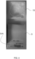
- Figure 4 shows another example of a package box 3 and a related, in this case empty plastic cup 13.
- the optical element 11 is disposed in the plastic cup 13 and both are disposed within the package box 3 made of carton. It is clear that for environmental reasons, that once the optical element 11 is unpacked, in the plastic parts on the one side and the carton parts on the other side need to be separated.
- the cups of different suppliers may be made of different types of plastic and that it would be interesting to differentiate and sort out the different types of plastic.
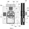
- figure 5 now presents a simplified scheme of an apparatus 100 for unpacking optical elements 11 disposed in a package box 3 which is closed.
- Figure 6 shows a synoptic view of different in particular control and interface aspects of apparatus 100.
- the apparatus 100 comprises in particular
- the apparatus further may comprise a second interface 116 (see figure 6 ) to exchange data with a job database 128 of the above cited LMSsystem (Lens Manufacturing System) containing data information related to lenses to be manufactured and a control unit 118 for comparing that the optical element 11 contained in a package box 3 complies with a lens manufacturing job to be carried out.
- LMSsystem Lis Manufacturing System
- the later comprises further a rotating plate 120 having several reception places 121 for receiving package boxes 3 and disposed at a regular angular interval, for example 90° to each other.
- Each reception place 121 is equipped with blocking members B which is configured to position and to immobilize a package box 3.
- the rotating plate 120 in this case defines for example four positions designated by roman numbers I, II, III, IV at 90°, at least three of them are associated respectively to units 110, 112 and 114 allowing to realize operations that will be described beneath in parallel.
- rotating plate 120 is not mandatory and one may envisage an apparatus where the different units are disposed along a line for example.
- the use of a rotating plate 120 allows having a compact footprint of the apparatus 100.
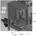
- the apparatus 100 which is linked to a conveyor 122 configured to convey transportation boxes 1 and is part of a not shown global conveyor system between different processing stations.
- the conveyor system is for example controlled by a lens manufacturing system "LMS".
- a transportation box 1 with two closed package boxes 3 is conveyed to a park position 124 of the apparatus 100 which is materialized in the figure 5 by a hashed line.
- a scanner 126 situated on the side of the conveyor opposite to the apparatus 100 scans for example both codes 7-A and 7-B of the job reference paper 5. This allows the LMS system to know which transportation box 1 is at park position 124 and contains package boxes 3 ready to be unpacked.
- the specific job(s) is for example memorized in above cited job database 128 of the LMS system.
- the apparatus 100 comprises a package identification unit 102 which is located and configured in a way that before a package box 3 is accepted in the apparatus 100 and unpacked, it is checked that the package boxes 3 in the transportation box 1 contain the optical elements 11 that are necessary and sufficient for realizing the lenses according to the specific job(s) present on the job reference paper 5.
- the transportation box 1 will be conveyed to a non-shown wait position where an operator can check what is going on.
- the apparatus 100 comprises to this extent a first suction unit 130 configured to take out one package box 3 out of the transportation box 1 and to present the package box to reader 104 for identification of the package box.
- a light emission cone 104-E of reader 104 is also drawn.
- the first suction unit 130 is configured to rotate the package box at most 3 times at 90° in order to try to read with reader 104 the identification code 9-A.
- the concerned package box 3 is put back in the transportation box 1 and conveyed to the wait position.
- the apparatus will first check through first interface 106 and via a communication channel in database 108 the parameters related to the dimensions and identity of package boxes 3, to the orientation of an optical element 11 within a package box 3, to the presence or not of a plastic cup 13 within a package box 3.
- the closed package box 3 belongs to a specific set of package boxes 3 that can be unpacked by apparatus 100. Furthermore, through second interface 116, it will be checked that the optical element 11 contained in the inspected package box 3 by reader 104 corresponds to the job data registered on the job reference paper 5. If either of these checks is negative, the whole transportation box 1 is sorted out in a wait position.
- the package identification unit 102 is in addition configured to determine the relative position of the optical element 11 within the package box 3 in taking into account the orientation of the bar-code or QR-code 9-A as determined by the reader 104.
- the closed package box 3 is transferred to reception place 121 at position I of rotating plate 120.
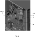
- the apparatus 100 comprises a robotized gripper 132 which is configured to take a package box from the first suction unit 130 and to place a package box 3 which is closed, in a way that the optical face to be processed (in general concave face 11-B) of the optical element 11 is oriented upwards.
- a robotized gripper 132 which is configured to take a package box from the first suction unit 130 and to place a package box 3 which is closed, in a way that the optical face to be processed (in general concave face 11-B) of the optical element 11 is oriented upwards.
- the robotized gripper 132 comprises mobile clamping fingers 134 (see for example figure 8 ) and is in addition configured to measure the width of the package box 3.
- the apparatus 100 then also checks if the width of the package box 3 corresponds to the attended width as memorized in the database 108. If the width does not correspond, then the concerned package box 3 is put back in the transportation box 1 and conveyed to the wait position.
- the control system of apparatus 100 commands rotation of plate 120 of 90° in order that the package box 3 is positioned in position II which correspond to the working zone of the laser cutting unit 110.
- the laser cutting unit 110 comprises a laser (for example a continuous infrared laser) 136, a mirror 138 and a laser beam scanning unit 140 which allows to direct the laser to different locations where the package box 3 has to be cut and to adapt the focus of the laser beam 142 which shall be located on the top side of the package box 3.
- a laser for example a continuous infrared laser
- the laser cutting unit 110 comprises furthermore an optical height sensor 144 configured to measure the height of a package box 3.
- the package box 3 may be a little bit damaged and for example squeezed.
- the apparatus 100 also comprises a third interface 146 to communicate via a communication channel with cutting pattern database 148.
- databases 108, 128 and 148 may be separate databases memorized on separated devices, or two or even three of these databases may be programmed as a unique database. These databases may be at the manufacturing facility or also for example in a cloud.
- interfaces 106, 116 and 146 may be realized as one interface or two interfaces.
- the measurement of the package box height allows to adjust precisely the focus of the laser beam 142 to get the best laser cutting conditions.
- the laser cutting unit 110 may send a laser beam in order to cut the top part of the package box 3 according to a dedicated cutting pattern supplied by the third interface 146 and associated to the identified package box 3.
- the package box 3 is represented with a continuous outer square line materializing the border or edge 150.
- Lines 152 represent laser cutting lines.
- the cutting patterns comprise for example at least one full cut line 152-F.
- Some cutting patterns comprise in addition at least one intermitted cut line 152-1 which can serve as a hinge during opening of the package box 3. This is the case in figures 10-B, 10-C (part of a circle) and figure 10-D .
- the cutting pattern of figure 10-D is for example well adapted when no plastic cup 13 is present in the package box 3.
- a protection shield (not shown) surrounds the laser and the package box 3 in order to protect from possible laser light that may be scattered.
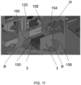
- the rotating plate 120 moves the cut package box 3 from position II to position III in the working zone of the opening and take out unit 112 comprising in particular a pivotable suction unit 154 and a take-out suction unit 156.
- the pivotable suction unit 154 is configured to get in contact with the top of the package box 3.
- the apparatus 100 is configured to control the pivotable suction unit 154 to get in contact with the top or cover face of the package box 3 and to suck this top face and to pull on the top face and to pivot. This will open the package box 3.
- the opening and take out unit 112 comprises a specific a hold-down device 156 for holding down the package box 3 during sucking operation.
- the hold-down device 156 may be formed by upward walls 158 which can get into contact with lateral sides of the package box 3 and 90° angled metal strips 160 that are arranged on the upwards walls 158 and get into contact with the peripheral part of the top face of the package box 3.
- the take-out suction unit 161 (see figure 12 ) will get into contact with the concave face of the optical element 11, suck and drag the optical element 11 out of the package box 3.
- the 90° angled metal strips 160 are dimensioned in width, such that when the optical element 11 is dragged out of the package box 3, a possible plastic cup 13 inside the package box 3 is also fixed and not dragged out.
- the robotized gripper 132 takes the optical element 11 by the edges and transfers it to the concerned transportation box 1.
- the apparatus 100 is configured to rotate rotating plate 120 in position IV to be in the working zone of the waste management unit 114.
- the waste management unit 114 comprises a mobile suction device 162 configured to take, if present, a plastic cup 13 out of the package box 3 and to evacuate it in a first dedicated waste container 164 and to evacuate then the empty package box 3 in a second dedicated waste container 166.
- the mobile suction device can realize a lift and swiveling movement in order to transfer from position IV a cup 13 if present and the package box 3 into the dedicated waste containers 164 or 166.
- the apparatus 100 is configured to rotate rotating plate 120 about 90° in order that the empty reception place 121 is rotation to position I again.
- the plastic cups 13 may be made of different type of plastic for certain suppliers (for example polystyrol and PET), with a specific need of waste treatment.
- the apparatus 100 may be adapted with more than one waste container for plastic, for example two waste containers or a container splitted into several, separate compartments for different types of plastics can be used.
- the apparatus 100 can unpack closed package boxes safely and with high speed. Waste management is quite efficiently realized. Laser cutting allows precise opening and does not generate for example small particles or dust that prevent good processing of the optical elements 11 once unpacked.
Landscapes
- Engineering & Computer Science (AREA)
- Mechanical Engineering (AREA)
- Physics & Mathematics (AREA)
- Artificial Intelligence (AREA)
- Toxicology (AREA)
- General Health & Medical Sciences (AREA)
- Electromagnetism (AREA)
- Computer Vision & Pattern Recognition (AREA)
- General Physics & Mathematics (AREA)
- Theoretical Computer Science (AREA)
- Robotics (AREA)
- Health & Medical Sciences (AREA)
- Packages (AREA)
- Eyeglasses (AREA)
- Laser Beam Processing (AREA)
Priority Applications (5)
| Application Number | Priority Date | Filing Date | Title |
|---|---|---|---|
| EP21205436.5A EP4173979A1 (de) | 2021-10-29 | 2021-10-29 | Vorrichtung zum auspacken eines optischen elements und zugehöriges verfahren |
| CN202280083686.8A CN118647550A (zh) | 2021-10-29 | 2022-10-12 | 用于取出光学元件的设备及相关方法 |
| PCT/EP2022/078341 WO2023072591A1 (en) | 2021-10-29 | 2022-10-12 | Apparatus for unpacking an optical element and related method |
| US18/704,735 US20250011028A1 (en) | 2021-10-29 | 2022-10-12 | Apparatus for unpacking an optical element and related method |
| EP22809645.9A EP4422977A1 (de) | 2021-10-29 | 2022-10-12 | Vorrichtung zum auspacken eines optischen elements und zugehöriges verfahren |
Applications Claiming Priority (1)
| Application Number | Priority Date | Filing Date | Title |
|---|---|---|---|
| EP21205436.5A EP4173979A1 (de) | 2021-10-29 | 2021-10-29 | Vorrichtung zum auspacken eines optischen elements und zugehöriges verfahren |
Publications (1)
| Publication Number | Publication Date |
|---|---|
| EP4173979A1 true EP4173979A1 (de) | 2023-05-03 |
Family
ID=78414444
Family Applications (2)
| Application Number | Title | Priority Date | Filing Date |
|---|---|---|---|
| EP21205436.5A Withdrawn EP4173979A1 (de) | 2021-10-29 | 2021-10-29 | Vorrichtung zum auspacken eines optischen elements und zugehöriges verfahren |
| EP22809645.9A Pending EP4422977A1 (de) | 2021-10-29 | 2022-10-12 | Vorrichtung zum auspacken eines optischen elements und zugehöriges verfahren |
Family Applications After (1)
| Application Number | Title | Priority Date | Filing Date |
|---|---|---|---|
| EP22809645.9A Pending EP4422977A1 (de) | 2021-10-29 | 2022-10-12 | Vorrichtung zum auspacken eines optischen elements und zugehöriges verfahren |
Country Status (4)
| Country | Link |
|---|---|
| US (1) | US20250011028A1 (de) |
| EP (2) | EP4173979A1 (de) |
| CN (1) | CN118647550A (de) |
| WO (1) | WO2023072591A1 (de) |
Cited By (2)
| Publication number | Priority date | Publication date | Assignee | Title |
|---|---|---|---|---|
| WO2025021885A2 (de) | 2023-07-24 | 2025-01-30 | Schneider Gmbh & Co. Kg | Vorrichtung und verfahren zum entpacken eines optischen werkstücks sowie verwendung |
| DE102023123387A1 (de) | 2023-07-24 | 2025-01-30 | Schneider Gmbh & Co. Kg | Vorrichtung und Verfahren zum Entpacken eines optischen Werkstücks sowie Verwendung |
Citations (6)
| Publication number | Priority date | Publication date | Assignee | Title |
|---|---|---|---|---|
| US20040235397A1 (en) | 2003-05-02 | 2004-11-25 | Oswin Lack | Container for and use of the latter in a production center for manufacturing individual spectacle lenses on prescription |
| WO2007067947A2 (en) * | 2005-12-09 | 2007-06-14 | Cornerstone Automation Systems, Inc. | Automated box opening apparatus |
| US20140182742A1 (en) * | 2012-11-29 | 2014-07-03 | Board Of Regents, The University Of Texas System | Robotic infusion mixer and transportable cartridge |
| WO2019123241A1 (en) * | 2017-12-22 | 2019-06-27 | Simac Tech S.R.L. | Deboxing station |
| US20200339298A1 (en) * | 2019-04-23 | 2020-10-29 | Walmart Apollo, Llc | System and method for opening containers |
| US20210130026A1 (en) | 2019-11-06 | 2021-05-06 | OptoTech AG | Method for unpacking a workpiece, unpacking apparatus and a processing apparatus having an unpacking apparatus of this kind |
-
2021
- 2021-10-29 EP EP21205436.5A patent/EP4173979A1/de not_active Withdrawn
-
2022
- 2022-10-12 US US18/704,735 patent/US20250011028A1/en active Pending
- 2022-10-12 CN CN202280083686.8A patent/CN118647550A/zh active Pending
- 2022-10-12 WO PCT/EP2022/078341 patent/WO2023072591A1/en not_active Ceased
- 2022-10-12 EP EP22809645.9A patent/EP4422977A1/de active Pending
Patent Citations (6)
| Publication number | Priority date | Publication date | Assignee | Title |
|---|---|---|---|---|
| US20040235397A1 (en) | 2003-05-02 | 2004-11-25 | Oswin Lack | Container for and use of the latter in a production center for manufacturing individual spectacle lenses on prescription |
| WO2007067947A2 (en) * | 2005-12-09 | 2007-06-14 | Cornerstone Automation Systems, Inc. | Automated box opening apparatus |
| US20140182742A1 (en) * | 2012-11-29 | 2014-07-03 | Board Of Regents, The University Of Texas System | Robotic infusion mixer and transportable cartridge |
| WO2019123241A1 (en) * | 2017-12-22 | 2019-06-27 | Simac Tech S.R.L. | Deboxing station |
| US20200339298A1 (en) * | 2019-04-23 | 2020-10-29 | Walmart Apollo, Llc | System and method for opening containers |
| US20210130026A1 (en) | 2019-11-06 | 2021-05-06 | OptoTech AG | Method for unpacking a workpiece, unpacking apparatus and a processing apparatus having an unpacking apparatus of this kind |
Cited By (2)
| Publication number | Priority date | Publication date | Assignee | Title |
|---|---|---|---|---|
| WO2025021885A2 (de) | 2023-07-24 | 2025-01-30 | Schneider Gmbh & Co. Kg | Vorrichtung und verfahren zum entpacken eines optischen werkstücks sowie verwendung |
| DE102023123387A1 (de) | 2023-07-24 | 2025-01-30 | Schneider Gmbh & Co. Kg | Vorrichtung und Verfahren zum Entpacken eines optischen Werkstücks sowie Verwendung |
Also Published As
| Publication number | Publication date |
|---|---|
| WO2023072591A1 (en) | 2023-05-04 |
| CN118647550A (zh) | 2024-09-13 |
| US20250011028A1 (en) | 2025-01-09 |
| EP4422977A1 (de) | 2024-09-04 |
Similar Documents
| Publication | Publication Date | Title |
|---|---|---|
| US11535412B2 (en) | Method for unpacking a workpiece, unpacking apparatus and a processing apparatus having an unpacking apparatus of this kind | |
| US20250011028A1 (en) | Apparatus for unpacking an optical element and related method | |
| US8490781B2 (en) | Transport container system for prescription spectacle lens production and method for transporting spectacle lenses and/or spectacle lens blanks | |
| EP0839603B1 (de) | Linsenbearbeitungszentrum | |
| CN114406626B (zh) | 一种中厚板试样自动化加工方法 | |
| EP2266753A1 (de) | Sperrstück zum Halten eines optischen Werkstücks, insbesondere eines Brillenglases, zu dessen Bearbeitung und Verfahren zur Herstellung von Brillengläsern entsprechend einer Vorgabe | |
| US20230278154A1 (en) | Method for Automated Positioning of a Blank in a Processing Machine | |
| CN109625734B (zh) | 一种暂存区智能控制方法 | |
| CN110450287A (zh) | 一种石材自动化生产方法 | |
| JP2002036083A (ja) | 眼鏡レンズ用レイアウト・ブロック・加工装置 | |
| KR100197091B1 (ko) | 웨이퍼 모깎기 장치 및 방법 | |
| US12459072B2 (en) | Apparatus and method for lens processing and processing device and measuring device for lenses | |
| JP2021509881A (ja) | 小包識別装置及び小包仕分け装置 | |
| CN109752864B (zh) | 用于根据处方单生产各个眼镜镜片的方法 | |
| CN110100209A (zh) | 用于标记工件的方法、对应的生产站和对应的装备方法 | |
| JP2022505346A (ja) | 仕分け工程を支援するために加工片の図解を表示するための方法 | |
| CN112340109A (zh) | 一种封装基板包装前自动分叉机装置及分叉方法 | |
| EP3936280A1 (de) | Transportträger für ein automatisiertes linsenherstellungsverfahren und zugehörige herstellungsanlage | |
| US6612789B2 (en) | Compact disc shaping apparatus and method | |
| JP4181563B2 (ja) | レンズホルダおよびそのホルダを使用した眼鏡レンズの加工方法 | |
| CN203318817U (zh) | 一种半自动贴标生产线 | |
| CN212576907U (zh) | 一种包装体内外码扫描分拨盘机构 | |
| JP4477548B2 (ja) | レンズ用レイアウト・ブロック装置およびその装置を用いた乱視用眼鏡レンズの加工方法 | |
| CN113495475B (zh) | 用于钟表指针的包装件 | |
| WO2024171543A1 (ja) | 搬送システム |
Legal Events
| Date | Code | Title | Description |
|---|---|---|---|
| PUAI | Public reference made under article 153(3) epc to a published international application that has entered the european phase |
Free format text: ORIGINAL CODE: 0009012 |
|
| STAA | Information on the status of an ep patent application or granted ep patent |
Free format text: STATUS: THE APPLICATION HAS BEEN PUBLISHED |
|
| AK | Designated contracting states |
Kind code of ref document: A1 Designated state(s): AL AT BE BG CH CY CZ DE DK EE ES FI FR GB GR HR HU IE IS IT LI LT LU LV MC MK MT NL NO PL PT RO RS SE SI SK SM TR |
|
| P01 | Opt-out of the competence of the unified patent court (upc) registered |
Effective date: 20230525 |
|
| STAA | Information on the status of an ep patent application or granted ep patent |
Free format text: STATUS: THE APPLICATION IS DEEMED TO BE WITHDRAWN |
|
| 18D | Application deemed to be withdrawn |
Effective date: 20231104 |