EP4173850A1 - Pneumatic tire - Google Patents
Pneumatic tire Download PDFInfo
- Publication number
- EP4173850A1 EP4173850A1 EP21827872.9A EP21827872A EP4173850A1 EP 4173850 A1 EP4173850 A1 EP 4173850A1 EP 21827872 A EP21827872 A EP 21827872A EP 4173850 A1 EP4173850 A1 EP 4173850A1
- Authority
- EP
- European Patent Office
- Prior art keywords
- regions
- ridges
- decorative
- decorative elements
- pneumatic tire
- Prior art date
- Legal status (The legal status is an assumption and is not a legal conclusion. Google has not performed a legal analysis and makes no representation as to the accuracy of the status listed.)
- Pending
Links
Images




Classifications
-
- B—PERFORMING OPERATIONS; TRANSPORTING
- B60—VEHICLES IN GENERAL
- B60C—VEHICLE TYRES; TYRE INFLATION; TYRE CHANGING; CONNECTING VALVES TO INFLATABLE ELASTIC BODIES IN GENERAL; DEVICES OR ARRANGEMENTS RELATED TO TYRES
- B60C13/00—Tyre sidewalls; Protecting, decorating, marking, or the like, thereof
- B60C13/001—Decorating, marking or the like
Definitions
- the present invention relates to a pneumatic tire and particularly relates to a pneumatic tire that can provide inconspicuous unevenness of a sidewall portion, improved decorativeness and visibility of a sidewall portion, and reduced drawing time at the time of designing the tire.
- a serration formed of a large number of ridges is formed on a sidewall portion (see, for example, Patent Documents 1 and 2).
- the size and curvature of the serration is changed according to a tire size, and then the serration is annularly disposed along a tire circumferential direction.
- such changes may take a large amount of drawing time at the time of designing the tire.
- An object of the present invention is to provide a pneumatic tire that can provide inconspicuous unevenness of a sidewall portion, improved decorativeness and visibility of the sidewall portion, and reduced drawing time at the time of designing the tire.
- a pneumatic tire includes a decorative portion on an outer surface of a sidewall portion.
- the decorative portion includes a plurality of decorative elements arranged in a step-like manner along reference lines parallel to each other, each of the decorative elements forms a hexagon in which three regions forming a parallelogram are disposed sharing adjacent sides of the three regions, a plurality of ridges extending in the same direction is formed in each of the regions of each of the decorative elements, and inclination directions of the ridges are different from one another in the three regions forming each of the decorative elements.
- the decorative portion in a pneumatic tire including a decorative portion on an outer surface of a sidewall portion, includes a plurality of decorative elements arranged in a step-like manner along reference lines parallel to each other, each of the decorative elements forms a hexagon in which three regions forming a parallelogram are disposed sharing adjacent sides of the three regions, a plurality of ridges extending in the same direction is formed in each of the regions of each of the decorative elements, and inclination directions of the ridges are different from one another in the three regions forming each of the decorative elements.
- the hexagonal decorative element has an optical illusion effect, allowing the decorativeness of the sidewall portion to be improved.
- a difference in contrast of light reflection caused by sparsity or density between the pattern portion in which the hexagonal decorative elements are gathered and a flat surface around a brand logo in the decorative portion increases attention to the sidewall portion and can improve the visibility of the sidewall portion (particularly the brand logo).
- the plurality of decorative elements is arranged along the reference lines parallel to each other, changing the size and curvature of the decoration in accordance with the tire size is unnecessary unlike the related art, and the above-described effects can be sufficiently obtained without such changes. This can reduce drawing time of the sidewall portion at the time of designing the tire.
- each of the regions of the decorative elements is preferably separated by a boundary portion formed of a protrusion portion or a recess portion, and the ridges in each of the regions of the decorative elements terminate at the boundary portion. This clarifies the boundary between each of the regions of the decorative elements and can effectively improve the decorativeness and visibility of the sidewall portion.
- An intersection angle between the ridges is preferably from 30° to 90°. This can effectively improve the unevenness of the sidewall portion as well as the decorativeness and visibility of the sidewall portion.
- a height of the ridges is preferably from 0.1 mm to 0.3 mm. This can effectively improve the unevenness of the sidewall portion as well as the decorativeness and visibility of the sidewall portion.
- a width of the boundary portion is preferably from 0.5 mm to 1.5 mm. This can effectively improve the decorativeness and visibility of the sidewall portion.
- a height or a depth of the boundary portion is preferably from 0.1 mm to 0.5 mm. This can effectively improve the decorativeness and visibility of the sidewall portion.
- FIGS. 1 to 3 illustrate an example of a pneumatic tire according to an embodiment of the present invention.
- a decorative portion 10 having an annular shape in the tire circumferential direction is formed on an outer surface of a sidewall portion 1 of the pneumatic tire.
- the decorative portion 10 includes a display portion 11 in which a manufacturer name of the tire or a brand logo are formed and a pattern portion 12 in which a plurality of decorative elements 20 is gathered to form a pattern.
- the display portion 11 and the pattern portion 12 are alternately arranged in the tire circumferential direction.
- ridges 31 to 33 which will be described below, are formed in the pattern portion 12, the ridges 31 to 33 are omitted in FIG. 1 to make a pattern according to an embodiment of the present invention visually easy to understand.
- the plurality of decorative elements 20 have the same shape in the pattern portion 12. Further, the plurality of decorative elements 20 is arranged in a step-like manner along a direction that is inclined with respect to the tire circumferential direction. The plurality of decorative elements 20 arranged in a step-like manner is continuously disposed in a plurality of rows in the tire radial direction. Thus disposing the plurality of decorative elements 20 in a step-like manner to form a row of stepped patterns, and further disposing a plurality of the rows of stepped patterns adjacently in the tire radial direction forms patterns of a step group including the plurality of the rows of stepped patterns on the pattern portion 12.
- a decorative element 20 includes three regions 21 to 23 that form a parallelogram.
- parallelogram in an embodiment of the present invention means a figure including a so-called parallelogram, a rhomboid, and a square.
- FIG. 2(b) illustrates an example in which the region 21 is a square and the regions 22 and 23 are parallelograms.
- the regions 21 to 23 are disposed sharing adjacent sides (boundary portions 25 described below).
- the decorative element 20 forms a hexagon as a whole. This hexagon is a figure formed by six sides and vertices when a contour line of the decorative element 20 formed of the three regions 21 to 23 in a plan view is considered.
- each decorative element 20 each forms a parallelogram in a plan view, and the combination of these regions 21 to 23 visually forms a cube shape.
- a cube shape hexagonal decorative element 20
- Such a cube shape is actually a flat shape but exerts an optical illusion effect by which a three-dimensional shape appears to be formed.
- the plurality of decorative elements 20 is arranged along reference lines L parallel to each other.
- the reference lines L are lines formed by connecting one corresponding point of each of the plurality of decorative elements 20 continuously arranged in a step-like manner and are, for example, lines formed by connecting one corner portion of the region 21 (square) as illustrated in FIG. 2(a) .
- the plurality of decorative elements 20 is disposed along the reference lines L, the plurality of decorative elements 20 is continuously arranged in a step-like manner along a direction that is inclined with respect to the tire circumferential direction but is not annularly disposed along the tire circumferential direction. Such a disposition of the decorative elements 20 enables all the decorative elements 20 disposed in the pattern portion 12 to have the same shape.
- the size and curvature of the decorative elements are changed according to the tire size, and the decorative elements are annularly disposed in the tire circumferential direction.
- the change of the size and curvature of the decorative elements causes the plurality of decorative elements not to be arranged along parallel reference lines.
- the decorative element located on the inner side in the tire radial direction and the decorative element located on the outer side in the tire radial direction are different in size, and all the decorative elements do not have the same shape.
- a plurality of ridges 31 to 33 extending in the same direction in each region is formed.
- the ridges 31 to 33 are formed protruding from the outer surface of the sidewall portion 1.
- the ridges 31 to 33 basically have the same height and width.
- the number of ridges 31 to 33 formed in each of the regions 21 to 23 may be the same or may be different.
- the ridges 31 to 33 are equally spaced within each region.
- the inclination directions of the ridges 31 to 33 disposed in the adjacent regions are different from one another.
- the ridges 31 in the region 21 and the ridges 32 in the region 22 extend in directions crossing each other
- the ridges 31 in the region 21 and the ridges 33 in the region 23 extend in directions crossing each other
- the ridges 32 in the region 22 and the ridges 33 in the region 23 extend in directions crossing each other. That is, one decorative element 20 has three inclination directions.
- the regions 21 to 23 are separated by the boundary portion 25 formed of a protrusion portion.
- the boundary portion 25 forms a side that is shared by the regions 21 to 23.
- the boundary portion 25 is formed protruding from the outer surface of the sidewall portion 1. All the ridges 31 to 33 in each of the regions 21 to 23 terminate at the boundary portion 25. Note that even in a case in which the boundary portion 25 is not formed in the decorative element 20, the ridges 31 to 33 in each of the regions 21 to 23 are not connected to one another.
- the decorative portion 10 includes a plurality of decorative elements 20 arranged in a step-like manner along reference lines L parallel to each other, each of the decorative elements 20 forms a hexagon in which the three regions 21 to 23 forming a parallelogram are disposed sharing adjacent sides of the three region s, a plurality of ridges 31 to 33 extending in the same direction is formed in each of the regions 21 to 23 of each of the decorative elements 20, and inclination directions of the ridges 31 to 33 are different from one another in the three regions 21 to 23 forming each of the decorative elements 20.
- This can make unevenness of the sidewall portion 1 inconspicuous.
- the hexagonal decorative element 20 has an optical illusion effect, the decorativeness of the sidewall portion 1 can be improved.
- a difference in contrast of light reflection caused by sparsity or density between the pattern portion 12 in which the hexagonal decorative elements 20 are gathered and a flat surface around a brand logo in the decorative portion 10 increases attention to the sidewall portion 1 and can improve the visibility of the sidewall portion 1 (particularly the brand logo).
- the plurality of decorative elements 20 is arranged along the reference lines L parallel to each other, changing the size and curvature of the decoration in accordance with the tire size is unnecessary unlike the related art, and the above-described effects can be sufficiently obtained without such changes. This can reduce the drawing time of the sidewall portion 1 at the time of designing the tire.
- each of the regions 21 to 23 of the decorative element 20 is separated by the boundary portion 25, and the ridges 31 to 33 in each of the regions 21 to 23 of the decorative element 20 terminate at the boundary portion 25. This clarifies a boundary between each of the regions 21 to 23 of the decorative element 20 and can effectively improve the decorativeness and visibility of the sidewall portion 1.
- a width W of the boundary portion 25 (see FIG. 3 ) is preferably from 0.5 mm to 1.5 mm and more preferably from 0.7 mm to 1.1 mm.
- Appropriately setting the width W of the boundary portion 25 in this manner clarifies the boundary between each of the regions 21 to 23 of the decorative element 20 and can effectively improve the decorativeness and visibility of the sidewall portion 1.
- the width W of the boundary portion 25 of less than 0.5 mm makes the boundary between each of the regions 21 to 23 of the decorative element 20 unclear and cannot sufficiently obtain the effect of improving the decorativeness and visibility of the sidewall portion 1.
- the width W of the boundary portion 25 of greater than 1.5 mm makes the boundary portion 25 excessively conspicuous and cannot obtain good visibility.
- a heightH of the boundary portion 25 is preferably from 0.1 mm to 0.5 mm and more preferably from 0.2 mm to 0.4 mm. Appropriately setting the height H the boundary portion 25 in this manner clarifies the boundary between each of the regions 21 to 23 of the decorative element 20 and can effectively improve the decorativeness and visibility of the sidewall portion 1.
- the height H of the boundary portion 25 of less than 0.1 mm makes the boundary between each of the regions 21 to 23 of the decorative element 20 unclear and cannot sufficiently obtain the effect of improving the decorativeness and visibility of the sidewall portion 1.
- the height H of the boundary portion 25 of greater than 0.5 mm makes the boundary portion 25 excessively conspicuous and cannot obtain good visibility.
- intersection angles ⁇ a to ⁇ c (see FIG. 2(b) ) of the ridges 31 to 33 are preferably from 30° to 90°.
- the intersection angles ⁇ a to ⁇ c mean an angle on the acute angle side of the ridges 31 to 33 formed in the adjacent regions 21 to 23 of the decorative element 20.
- the intersection angle ⁇ a between the ridge 31 in the region 21 and the ridge 32 in the region 22 is 90°
- the intersection angle ⁇ b between the ridge 31 in the region 21 and the ridge 33 in the region 23 is 45°
- the intersection angle ⁇ c between the ridge 32 in the region 22 and the ridge 33 in the region 23 is 45°.
- a height h of the ridges 31 to 33 is preferably from 0.1 mm to 0.3 mm. Furthermore, the height h of each of the ridges 31 to 33 is preferably lower than the height H of the boundary portion 25. Appropriately setting the height h of the ridges 31 to 33 in this manner can effectively improve the unevenness of the sidewall portion 1 and can effectively improve the decorativeness and visibility of the sidewall portion 1.
- the height h of the ridges 31 to 33 of less than 0.1 mm cannot sufficiently obtain the effect of improving unevenness of the sidewall portion 1.
- the height h of the ridges 31 to 33 of greater than 0.3 mm makes the ridges 31 to 33 excessively conspicuous and cannot obtain good visibility.
- FIG. 4 illustrates one region of the decorative element formed on the sidewall portion of a modified example of the pneumatic tire according to the embodiment of the present invention.
- the regions 21 to 23 of the decorative element 20 are separated by the boundary portion 25 formed of a protrusion portion.
- the regions are separated by a boundary portion 26 formed of a recess portion.
- the pneumatic tire according to the embodiment illustrated in FIG. 4 has the same structure as the pneumatic tire of FIGS. 1 to 3 except that the boundary portion 26 formed of a recess portion is formed in the pattern portion 12.
- the boundary portion 26 is recessed from the outer surface of the sidewall portion 1.
- a depth D of the boundary portion 26 is preferably from 0.1 mm to 0.5 mm and more preferably from 0.2 mm to 0.4 mm.
- FIGS. 5 and 6 each illustrate another modified example of the pneumatic tire according to the embodiment of the present invention.
- FIG. 1 in the pattern portion 12, two rows of stepped patterns (the plurality of decorative elements 20 continuously arranged in a step-like manner) are disposed in the tire radial direction.
- FIG. 5 one row of stepped patterns is disposed in the tire radial direction
- FIG. 6 three rows of stepped patterns are disposed in the tire radial direction.
- the pneumatic tires of the embodiments of FIGS. 5 and 6 both have the same structure as the pneumatic tire of FIGS. 1 to 3 except that the number of rows of stepped patterns in the tire radial direction is different.
- the number of rows of stepped patterns in the tire radial direction is preferably 1 to 3 rows and is more preferably 2 rows.
- the number of rows of stepped patterns in the tire radial direction is the maximum number of the decorative element 20 in the tire radial direction disposed in the pattern portion 12, targeting at the hexagonal decorative element 20 whose entirety is contained within the pattern portion 12.
- the ridges 31 to 33 are formed in the pattern portion 12, but the ridges 31 to 33 are omitted in FIGS. 5 and 6 to make a pattern according to an embodiment of the present invention visually easy to understand.
- the tires according to Conventional Example and Examples 1 to 3 were manufactured.
- the pneumatic tires have a tire size of 195/60R16 and have the decorative portion on the outer surface of the sidewall portion.
- the tires are set for the pattern of the pattern portion, the width of the boundary portion, and the number of rows of the stepped pattern in the tire radial direction, as indicated in Table 1.
- Example 7 the pattern of the pattern portion illustrated in FIG. 7 is employed, and only a plurality of ridges having a height of 0.2 mm is disposed in the pattern portion.
- Example 1 the pattern of the pattern portion illustrated in FIG. 1 is employed.
- Example 2 the pattern of the pattern portion illustrated in FIG. 5 is employed.
- Example 3 the pattern of the pattern portion illustrated in FIG. 6 is employed.
- each region of the decorative element is separated by the boundary portion formed of a protrusion portion, the ridges of each region of the decorative element had a structure in which the ridges terminate at the boundary portion, the height of the ridges is set to 0.2 mm, and the height of the boundary portion is set to 0.3 mm.
- Pattern Portion Decorativeness
- Examples 1 to 3 had improved the difficulty in identifying unevenness, the decorativeness of the pattern portion, the visibility of the display portion, and drawing time of pattern portion compared with those of Conventional Example.
- the decorative elements formed in the pattern portion were well balanced in size compared with those of Examples 2 and 3.
Landscapes
- Engineering & Computer Science (AREA)
- Mechanical Engineering (AREA)
- Tires In General (AREA)
Abstract
Description
- The present invention relates to a pneumatic tire and particularly relates to a pneumatic tire that can provide inconspicuous unevenness of a sidewall portion, improved decorativeness and visibility of a sidewall portion, and reduced drawing time at the time of designing the tire.
- To make unevenness of the sidewall portion inconspicuous, in a pneumatic tire, a serration formed of a large number of ridges is formed on a sidewall portion (see, for example,
Patent Documents 1 and 2). In disposing the serration on the sidewall portion, typically, the size and curvature of the serration is changed according to a tire size, and then the serration is annularly disposed along a tire circumferential direction. Unfortunately, such changes may take a large amount of drawing time at the time of designing the tire. -
- Patent Document 1:
JP2013-35313 A - PatentDocument2:
WO 2018/162308 - An object of the present invention is to provide a pneumatic tire that can provide inconspicuous unevenness of a sidewall portion, improved decorativeness and visibility of the sidewall portion, and reduced drawing time at the time of designing the tire.
- To achieve the object described above, a pneumatic tire according to an embodiment of the present invention includes a decorative portion on an outer surface of a sidewall portion. In the pneumatic tire, the decorative portion includes a plurality of decorative elements arranged in a step-like manner along reference lines parallel to each other, each of the decorative elements forms a hexagon in which three regions forming a parallelogram are disposed sharing adjacent sides of the three regions, a plurality of ridges extending in the same direction is formed in each of the regions of each of the decorative elements, and inclination directions of the ridges are different from one another in the three regions forming each of the decorative elements.
- According to an embodiment of the present invention, in a pneumatic tire including a decorative portion on an outer surface of a sidewall portion, the decorative portion includes a plurality of decorative elements arranged in a step-like manner along reference lines parallel to each other, each of the decorative elements forms a hexagon in which three regions forming a parallelogram are disposed sharing adjacent sides of the three regions, a plurality of ridges extending in the same direction is formed in each of the regions of each of the decorative elements, and inclination directions of the ridges are different from one another in the three regions forming each of the decorative elements. This can improve poor appearance of the sidewall portion. In particular, the hexagonal decorative element has an optical illusion effect, allowing the decorativeness of the sidewall portion to be improved. In addition, a difference in contrast of light reflection caused by sparsity or density between the pattern portion in which the hexagonal decorative elements are gathered and a flat surface around a brand logo in the decorative portion increases attention to the sidewall portion and can improve the visibility of the sidewall portion (particularly the brand logo). Furthermore, since the plurality of decorative elements is arranged along the reference lines parallel to each other, changing the size and curvature of the decoration in accordance with the tire size is unnecessary unlike the related art, and the above-described effects can be sufficiently obtained without such changes. This can reduce drawing time of the sidewall portion at the time of designing the tire.
- In a pneumatic tire according to an embodiment of the present invention, preferably, each of the regions of the decorative elements is preferably separated by a boundary portion formed of a protrusion portion or a recess portion, and the ridges in each of the regions of the decorative elements terminate at the boundary portion. This clarifies the boundary between each of the regions of the decorative elements and can effectively improve the decorativeness and visibility of the sidewall portion.
- An intersection angle between the ridges is preferably from 30° to 90°. This can effectively improve the unevenness of the sidewall portion as well as the decorativeness and visibility of the sidewall portion.
- A height of the ridges is preferably from 0.1 mm to 0.3 mm. This can effectively improve the unevenness of the sidewall portion as well as the decorativeness and visibility of the sidewall portion.
- A width of the boundary portion is preferably from 0.5 mm to 1.5 mm. This can effectively improve the decorativeness and visibility of the sidewall portion.
- A height or a depth of the boundary portion is preferably from 0.1 mm to 0.5 mm. This can effectively improve the decorativeness and visibility of the sidewall portion.
-
-
FIG. 1 is a side view illustrating an example of a pneumatic tire according to an embodiment of the present invention. -
FIGS. 2(a) and (b) are enlarged side views illustrating a main portion of the pneumatic tire ofFIG. 1 .FIG. 2(a) illustrates a pattern portion in which a plurality of decorative elements is gathered.FIG. 2(b) schematically illustrates one decorative element. -
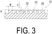
FIG. 3 is a cross-sectional view illustrating one region of a decorative element formed on a sidewall portion of the pneumatic tire ofFIG. 1 . -
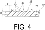
FIG. 4 is a cross-sectional view illustrating a region of a decorative element formed on a sidewall portion of a modified example of a pneumatic tire according to an embodiment of the present invention. -
FIG. 5 is a side view illustrating another modified example of a pneumatic tire according to an embodiment of the present invention. -
FIG. 6 is a side view illustrating another modified example of a pneumatic tire according to an embodiment of the present invention. -
FIG. 7 is a side view illustrating a known pneumatic tire. - Configurations of the present invention will be described in detail below with reference to the accompanying drawings.
FIGS. 1 to 3 illustrate an example of a pneumatic tire according to an embodiment of the present invention. - As illustrated in
FIG. 1 , adecorative portion 10 having an annular shape in the tire circumferential direction is formed on an outer surface of asidewall portion 1 of the pneumatic tire. Thedecorative portion 10 includes adisplay portion 11 in which a manufacturer name of the tire or a brand logo are formed and apattern portion 12 in which a plurality ofdecorative elements 20 is gathered to form a pattern. Thedisplay portion 11 and thepattern portion 12 are alternately arranged in the tire circumferential direction. Althoughridges 31 to 33, which will be described below, are formed in thepattern portion 12, theridges 31 to 33 are omitted inFIG. 1 to make a pattern according to an embodiment of the present invention visually easy to understand. - As illustrated in
FIG. 2(a) , the plurality ofdecorative elements 20 have the same shape in thepattern portion 12. Further, the plurality ofdecorative elements 20 is arranged in a step-like manner along a direction that is inclined with respect to the tire circumferential direction. The plurality ofdecorative elements 20 arranged in a step-like manner is continuously disposed in a plurality of rows in the tire radial direction. Thus disposing the plurality ofdecorative elements 20 in a step-like manner to form a row of stepped patterns, and further disposing a plurality of the rows of stepped patterns adjacently in the tire radial direction forms patterns of a step group including the plurality of the rows of stepped patterns on thepattern portion 12. - As illustrated in
FIG. 2(b) , adecorative element 20 includes threeregions 21 to 23 that form a parallelogram. Here, "parallelogram" in an embodiment of the present invention means a figure including a so-called parallelogram, a rhomboid, and a square.FIG. 2(b) illustrates an example in which theregion 21 is a square and theregions regions 21 to 23 are disposed sharing adjacent sides (boundary portions 25 described below). By disposing the threeregions 21 to 23 adjacently in this way, thedecorative element 20 forms a hexagon as a whole. This hexagon is a figure formed by six sides and vertices when a contour line of thedecorative element 20 formed of the threeregions 21 to 23 in a plan view is considered. - The three
regions 21 to 23 forming eachdecorative element 20 each forms a parallelogram in a plan view, and the combination of theseregions 21 to 23 visually forms a cube shape. Such a cube shape (hexagonal decorative element 20) is actually a flat shape but exerts an optical illusion effect by which a three-dimensional shape appears to be formed. - Further, the plurality of
decorative elements 20 is arranged along reference lines L parallel to each other. The reference lines L are lines formed by connecting one corresponding point of each of the plurality ofdecorative elements 20 continuously arranged in a step-like manner and are, for example, lines formed by connecting one corner portion of the region 21 (square) as illustrated inFIG. 2(a) . When the plurality ofdecorative elements 20 is disposed along the reference lines L, the plurality ofdecorative elements 20 is continuously arranged in a step-like manner along a direction that is inclined with respect to the tire circumferential direction but is not annularly disposed along the tire circumferential direction. Such a disposition of thedecorative elements 20 enables all thedecorative elements 20 disposed in thepattern portion 12 to have the same shape. - On the other hand, in a known pneumatic tire in which a plurality of decorative elements having a specific shape is regularly disposed along the tire circumferential direction or the tire radial direction, typically, the size and curvature of the decorative elements are changed according to the tire size, and the decorative elements are annularly disposed in the tire circumferential direction. The change of the size and curvature of the decorative elements causes the plurality of decorative elements not to be arranged along parallel reference lines. Further, the decorative element located on the inner side in the tire radial direction and the decorative element located on the outer side in the tire radial direction are different in size, and all the decorative elements do not have the same shape.
- In the
regions 21 to 23 forming each of thedecorative elements 20, a plurality ofridges 31 to 33 extending in the same direction in each region is formed. Theridges 31 to 33 are formed protruding from the outer surface of thesidewall portion 1. Theridges 31 to 33 basically have the same height and width. The number ofridges 31 to 33 formed in each of theregions 21 to 23 may be the same or may be different. Preferably, theridges 31 to 33 are equally spaced within each region. - Further, the inclination directions of the
ridges 31 to 33 disposed in the adjacent regions are different from one another. Specifically, theridges 31 in theregion 21 and theridges 32 in theregion 22 extend in directions crossing each other, theridges 31 in theregion 21 and theridges 33 in theregion 23 extend in directions crossing each other, and theridges 32 in theregion 22 and theridges 33 in theregion 23 extend in directions crossing each other. That is, onedecorative element 20 has three inclination directions. - In such a
decorative element 20, theregions 21 to 23 are separated by theboundary portion 25 formed of a protrusion portion. In other words, theboundary portion 25 forms a side that is shared by theregions 21 to 23. Further, theboundary portion 25 is formed protruding from the outer surface of thesidewall portion 1. All theridges 31 to 33 in each of theregions 21 to 23 terminate at theboundary portion 25. Note that even in a case in which theboundary portion 25 is not formed in thedecorative element 20, theridges 31 to 33 in each of theregions 21 to 23 are not connected to one another. - In the pneumatic tire described above, the
decorative portion 10 includes a plurality ofdecorative elements 20 arranged in a step-like manner along reference lines L parallel to each other, each of thedecorative elements 20 forms a hexagon in which the threeregions 21 to 23 forming a parallelogram are disposed sharing adjacent sides of the three region s, a plurality ofridges 31 to 33 extending in the same direction is formed in each of theregions 21 to 23 of each of thedecorative elements 20, and inclination directions of theridges 31 to 33 are different from one another in the threeregions 21 to 23 forming each of thedecorative elements 20. This can make unevenness of thesidewall portion 1 inconspicuous. In particular, since the hexagonaldecorative element 20 has an optical illusion effect, the decorativeness of thesidewall portion 1 can be improved. In addition, a difference in contrast of light reflection caused by sparsity or density between thepattern portion 12 in which the hexagonaldecorative elements 20 are gathered and a flat surface around a brand logo in thedecorative portion 10 increases attention to thesidewall portion 1 and can improve the visibility of the sidewall portion 1 (particularly the brand logo). Furthermore, since the plurality ofdecorative elements 20 is arranged along the reference lines L parallel to each other, changing the size and curvature of the decoration in accordance with the tire size is unnecessary unlike the related art, and the above-described effects can be sufficiently obtained without such changes. This can reduce the drawing time of thesidewall portion 1 at the time of designing the tire. - Furthermore, each of the
regions 21 to 23 of thedecorative element 20 is separated by theboundary portion 25, and theridges 31 to 33 in each of theregions 21 to 23 of thedecorative element 20 terminate at theboundary portion 25. This clarifies a boundary between each of theregions 21 to 23 of thedecorative element 20 and can effectively improve the decorativeness and visibility of thesidewall portion 1. - In the pneumatic tire described above, a width W of the boundary portion 25 (see
FIG. 3 ) is preferably from 0.5 mm to 1.5 mm and more preferably from 0.7 mm to 1.1 mm. Appropriately setting the width W of theboundary portion 25 in this manner clarifies the boundary between each of theregions 21 to 23 of thedecorative element 20 and can effectively improve the decorativeness and visibility of thesidewall portion 1. - Here, the width W of the
boundary portion 25 of less than 0.5 mm makes the boundary between each of theregions 21 to 23 of thedecorative element 20 unclear and cannot sufficiently obtain the effect of improving the decorativeness and visibility of thesidewall portion 1. On the contrary, the width W of theboundary portion 25 of greater than 1.5 mm makes theboundary portion 25 excessively conspicuous and cannot obtain good visibility. - Further, a heightH of the boundary portion 25 (see
FIG. 3 ) is preferably from 0.1 mm to 0.5 mm and more preferably from 0.2 mm to 0.4 mm. Appropriately setting the height H theboundary portion 25 in this manner clarifies the boundary between each of theregions 21 to 23 of thedecorative element 20 and can effectively improve the decorativeness and visibility of thesidewall portion 1. - Here, the height H of the
boundary portion 25 of less than 0.1 mm makes the boundary between each of theregions 21 to 23 of thedecorative element 20 unclear and cannot sufficiently obtain the effect of improving the decorativeness and visibility of thesidewall portion 1. On the contrary, the height H of theboundary portion 25 of greater than 0.5 mm makes theboundary portion 25 excessively conspicuous and cannot obtain good visibility. - In the pneumatic tire described above, intersection angles θa to θc (see
FIG. 2(b) ) of theridges 31 to 33 are preferably from 30° to 90°. At this time, the intersection angles θa to θc mean an angle on the acute angle side of theridges 31 to 33 formed in theadjacent regions 21 to 23 of thedecorative element 20. InFIG. 2(b) , the intersection angle θa between theridge 31 in theregion 21 and theridge 32 in theregion 22 is 90°, the intersection angle θb between theridge 31 in theregion 21 and theridge 33 in theregion 23 is 45°, and the intersection angle θc between theridge 32 in theregion 22 and theridge 33 in theregion 23 is 45°. Appropriately setting the intersection angles θa to θc of theridges 31 to 33 in this manner effectively improves the unevenness of thesidewall portion 1 and can effectively improve the decorativeness and visibility of thesidewall portion 1. - Further, a height h of the
ridges 31 to 33 (seeFIG. 3 ) is preferably from 0.1 mm to 0.3 mm. Furthermore, the height h of each of theridges 31 to 33 is preferably lower than the height H of theboundary portion 25. Appropriately setting the height h of theridges 31 to 33 in this manner can effectively improve the unevenness of thesidewall portion 1 and can effectively improve the decorativeness and visibility of thesidewall portion 1. - Here, the height h of the
ridges 31 to 33 of less than 0.1 mm cannot sufficiently obtain the effect of improving unevenness of thesidewall portion 1. On the contrary, the height h of theridges 31 to 33 of greater than 0.3 mm makes theridges 31 to 33 excessively conspicuous and cannot obtain good visibility. -
FIG. 4 illustrates one region of the decorative element formed on the sidewall portion of a modified example of the pneumatic tire according to the embodiment of the present invention. InFIG. 3 , theregions 21 to 23 of thedecorative element 20 are separated by theboundary portion 25 formed of a protrusion portion. InFIG. 4 , the regions are separated by aboundary portion 26 formed of a recess portion. The pneumatic tire according to the embodiment illustrated inFIG. 4 has the same structure as the pneumatic tire ofFIGS. 1 to 3 except that theboundary portion 26 formed of a recess portion is formed in thepattern portion 12. Theboundary portion 26 is recessed from the outer surface of thesidewall portion 1. Further, a depth D of the boundary portion 26 (seeFIG. 4 ) is preferably from 0.1 mm to 0.5 mm and more preferably from 0.2 mm to 0.4 mm. -
FIGS. 5 and6 each illustrate another modified example of the pneumatic tire according to the embodiment of the present invention. InFIG. 1 , in thepattern portion 12, two rows of stepped patterns (the plurality ofdecorative elements 20 continuously arranged in a step-like manner) are disposed in the tire radial direction. However, inFIG. 5 , one row of stepped patterns is disposed in the tire radial direction, and inFIG. 6 , three rows of stepped patterns are disposed in the tire radial direction. The pneumatic tires of the embodiments ofFIGS. 5 and6 both have the same structure as the pneumatic tire ofFIGS. 1 to 3 except that the number of rows of stepped patterns in the tire radial direction is different. To improve the balance of the cube shape (hexagonal decorative element 20), in thepattern portion 12, the number of rows of stepped patterns in the tire radial direction is preferably 1 to 3 rows and is more preferably 2 rows. Here, the number of rows of stepped patterns in the tire radial direction is the maximum number of thedecorative element 20 in the tire radial direction disposed in thepattern portion 12, targeting at the hexagonaldecorative element 20 whose entirety is contained within thepattern portion 12. Note that theridges 31 to 33 are formed in thepattern portion 12, but theridges 31 to 33 are omitted inFIGS. 5 and6 to make a pattern according to an embodiment of the present invention visually easy to understand. - The tires according to Conventional Example and Examples 1 to 3 were manufactured. The pneumatic tires have a tire size of 195/60R16 and have the decorative portion on the outer surface of the sidewall portion. The tires are set for the pattern of the pattern portion, the width of the boundary portion, and the number of rows of the stepped pattern in the tire radial direction, as indicated in Table 1.
- In Conventional Example, the pattern of the pattern portion illustrated in
FIG. 7 is employed, and only a plurality of ridges having a height of 0.2 mm is disposed in the pattern portion. In Example 1, the pattern of the pattern portion illustrated inFIG. 1 is employed. In Example 2, the pattern of the pattern portion illustrated inFIG. 5 is employed. In Example 3, the pattern of the pattern portion illustrated inFIG. 6 is employed. Additionally, in Examples 1 to 3, each region of the decorative element is separated by the boundary portion formed of a protrusion portion, the ridges of each region of the decorative element had a structure in which the ridges terminate at the boundary portion, the height of the ridges is set to 0.2 mm, and the height of the boundary portion is set to 0.3 mm. - For these test tires, difficulty in recognizing the unevenness, decorativeness of the pattern portion, visibility of the display portion, and drawing time of the pattern portion were evaluated using test methods described below, and the results are indicated in Table 1.
- For each test tire, a tester visually recognized the unevenness of the sidewall portion and evaluated the difficulty in recognizing the unevenness. Evaluation results are expressed as index values with the value of Conventional Example being defined as 100. Largerindex values indicate that recognition of the unevenness is more difficult, and the unevenness is less conspicuous.
- For each test tire, a tester visually recognized the sidewall portion, and evaluated the decorativeness of the pattern portion. Evaluation results are expressed as index values with the value of Conventional Example being defined as 100. Larger index values indicate superior decorativeness.
- For each test tire, a tester visually recognized the sidewall portion, and evaluated the visibility of the brand logo of the display portion. Evaluation results are expressed as index values with the value of Conventional Example being defined as 100. Larger index values indicate superior visibility of the brand logo.
- For each test tire, time (minutes) required to draw the pattern portion of the sidewall portion was measured. Evaluation results are expressed as index values with the value of Conventional Example being defined as 100. Smaller index values indicate shorter drawing time.
Table 1 Conventional Example Example 1 Example 2 Example 3 Pattern of pattern portion FIG. 7 FIG. 1 FIG. 5 FIG. 6 Width of boundary portion (mm) - 0.9 1.5 0.6 Number of rows of stepped pattern in tire radial direction - 2 1 3 Difficulty in recognizing unevenness 100 105 105 105 Decorativeness of pattern portion 100 115 105 110 Visibility of display portion 100 110 105 115 Drawing time of pattern portion 100 85 80 90 - As can be seen from Table 1, Examples 1 to 3 had improved the difficulty in identifying unevenness, the decorativeness of the pattern portion, the visibility of the display portion, and drawing time of pattern portion compared with those of Conventional Example. In particular, in Example 1, the decorative elements formed in the pattern portion were well balanced in size compared with those of Examples 2 and 3.
-
- 1 Sidewall portion
- 10 Decorative portion
- 20 Decorative element
- 21 to 23 Region
- 25, 26 Boundary portion
- 31 to 33 Ridge
Claims (6)
- A pneumatic tire, comprisinga decorative portion on an outer surface of a sidewall portion,the decorative portion comprising a plurality of decorative elements arranged in a step-like manner along reference lines parallel to each other,each of the decorative elements forming a hexagon in which three regions forming a parallelogram are disposed sharing adjacent sides of the three regions,a plurality of ridges extending in the same direction being formed in each of the regions of each of the decorative elements, andinclination directions of the ridges being different from one another in the three regions forming each of the decorative elements.
- The pneumatic tire according to claim 1, whereineach of the regions of the decorative elements is separated by a boundary portion formed of a protrusion portion or a recess portion, andthe ridges in each of the regions of the decorative elements terminate at the boundary portion.
- The pneumatic tire according to claim 1 or 2, wherein an intersection angle between the ridges is from 30° to 90°.
- The pneumatic tire according to any one of claims 1 to 3, wherein a height of the ridges is from 0.1 mm to 0.3 mm.
- The pneumatic tire according to claim 2, wherein a width of the boundary portion is from 0.5 mm to 1.5 mm.
- The pneumatic tire according to claim 2 or 5, wherein a height or a depth of the boundary portion is from 0.1 mm to 0.5 mm.
Applications Claiming Priority (2)
| Application Number | Priority Date | Filing Date | Title |
|---|---|---|---|
| JP2020108616A JP7421102B2 (en) | 2020-06-24 | 2020-06-24 | pneumatic tires |
| PCT/JP2021/023934 WO2021261553A1 (en) | 2020-06-24 | 2021-06-24 | Pneumatic tire |
Publications (2)
| Publication Number | Publication Date |
|---|---|
| EP4173850A1 true EP4173850A1 (en) | 2023-05-03 |
| EP4173850A4 EP4173850A4 (en) | 2024-07-17 |
Family
ID=79281315
Family Applications (1)
| Application Number | Title | Priority Date | Filing Date |
|---|---|---|---|
| EP21827872.9A Pending EP4173850A4 (en) | 2020-06-24 | 2021-06-24 | TIRE |
Country Status (5)
| Country | Link |
|---|---|
| US (1) | US12617242B2 (en) |
| EP (1) | EP4173850A4 (en) |
| JP (1) | JP7421102B2 (en) |
| CN (1) | CN115697726B (en) |
| WO (1) | WO2021261553A1 (en) |
Families Citing this family (7)
| Publication number | Priority date | Publication date | Assignee | Title |
|---|---|---|---|---|
| JP2019104385A (en) * | 2017-12-12 | 2019-06-27 | 株式会社ブリヂストン | Decorative body |
| DE102022202881A1 (en) * | 2022-03-24 | 2023-09-28 | Continental Reifen Deutschland Gmbh | Vehicle tires |
| US12485707B2 (en) * | 2022-04-04 | 2025-12-02 | The Goodyear Tire & Rubber Company | High contrast patterns for sidewall or tread |
| DE102022203403A1 (en) * | 2022-04-06 | 2023-10-12 | Continental Reifen Deutschland Gmbh | Vehicle tires |
| TWI819741B (en) * | 2022-08-09 | 2023-10-21 | 正新橡膠工業股份有限公司 | Tire and its structure for enhancing visual contrast of tire edge |
| EP4385764B1 (en) * | 2022-12-13 | 2025-10-08 | The Goodyear Tire & Rubber Company | Tire comprising a pattern providing a high contrast |
| JP7671890B1 (en) * | 2024-02-21 | 2025-05-02 | Toyo Tire株式会社 | Pneumatic tire and mold for molding pneumatic tire |
Family Cites Families (13)
| Publication number | Priority date | Publication date | Assignee | Title |
|---|---|---|---|---|
| JP5230229B2 (en) | 2007-04-05 | 2013-07-10 | 東洋ゴム工業株式会社 | Pneumatic tire |
| EP2502758B1 (en) * | 2009-11-19 | 2014-11-12 | Bridgestone Corporation | Tire |
| JP5364556B2 (en) | 2009-12-15 | 2013-12-11 | 株式会社ブリヂストン | tire |
| JP4911332B2 (en) * | 2010-09-08 | 2012-04-04 | 横浜ゴム株式会社 | Pneumatic tire and its vulcanization mold |
| JP5621611B2 (en) * | 2011-01-18 | 2014-11-12 | 横浜ゴム株式会社 | Pneumatic tire |
| JP5310805B2 (en) * | 2011-08-03 | 2013-10-09 | 横浜ゴム株式会社 | Pneumatic tire |
| US9919567B2 (en) * | 2012-02-17 | 2018-03-20 | Bridgestone Corporation | Tire and tire manufacturing method |
| JP5789274B2 (en) | 2013-01-16 | 2015-10-07 | 住友ゴム工業株式会社 | Pneumatic tire |
| JP6467261B2 (en) | 2015-03-27 | 2019-02-06 | 住友ゴム工業株式会社 | Pneumatic tire |
| JP6848502B2 (en) * | 2017-02-14 | 2021-03-24 | 横浜ゴム株式会社 | Pneumatic tires |
| FR3063455B1 (en) * | 2017-03-06 | 2021-11-26 | Michelin & Cie | PNEUMATIC WITH A TEXTURE ON A SIDE |
| JP6990578B2 (en) * | 2017-12-25 | 2022-01-12 | Toyo Tire株式会社 | Pneumatic tires |
| JP2019119268A (en) | 2017-12-28 | 2019-07-22 | 住友ゴム工業株式会社 | tire |
-
2020
- 2020-06-24 JP JP2020108616A patent/JP7421102B2/en active Active
-
2021
- 2021-06-24 CN CN202180036778.6A patent/CN115697726B/en active Active
- 2021-06-24 EP EP21827872.9A patent/EP4173850A4/en active Pending
- 2021-06-24 US US18/002,404 patent/US12617242B2/en active Active
- 2021-06-24 WO PCT/JP2021/023934 patent/WO2021261553A1/en not_active Ceased
Also Published As
| Publication number | Publication date |
|---|---|
| CN115697726A (en) | 2023-02-03 |
| US20230234402A1 (en) | 2023-07-27 |
| CN115697726B (en) | 2026-03-13 |
| WO2021261553A1 (en) | 2021-12-30 |
| EP4173850A4 (en) | 2024-07-17 |
| US12617242B2 (en) | 2026-05-05 |
| JP2022006410A (en) | 2022-01-13 |
| JP7421102B2 (en) | 2024-01-24 |
Similar Documents
| Publication | Publication Date | Title |
|---|---|---|
| US12617242B2 (en) | Pneumatic tire | |
| US10532614B2 (en) | Tire | |
| US8573273B2 (en) | Pneumatic tire | |
| EP3412477B1 (en) | Tire | |
| JP4947225B1 (en) | Pneumatic tire | |
| WO2011062241A1 (en) | Tire | |
| EP3409509B1 (en) | Tire | |
| CN110382261A (en) | The tire in textured portion is set on side wall | |
| US11597240B2 (en) | Decorative body | |
| EP3489040A1 (en) | Tire | |
| CN104339988A (en) | Pneumatic tire | |
| US12485707B2 (en) | High contrast patterns for sidewall or tread | |
| JP2020097300A (en) | Pneumatic tire | |
| JP2015168431A (en) | tire | |
| WO2019111856A1 (en) | Tire | |
| EP3192675B1 (en) | Pneumatic tire | |
| US20100154473A1 (en) | Round brilliant cut diamond and its incision method | |
| RU2805454C1 (en) | Air tire | |
| JP2016175457A (en) | tire | |
| JP7168525B2 (en) | pneumatic tire | |
| JP2005053248A (en) | Tire | |
| US20200298630A1 (en) | Decorative body | |
| WO2022195960A1 (en) | Tire | |
| US11479061B2 (en) | Tire | |
| CN221469235U (en) | Bear diamond with equal section |
Legal Events
| Date | Code | Title | Description |
|---|---|---|---|
| STAA | Information on the status of an ep patent application or granted ep patent |
Free format text: STATUS: THE INTERNATIONAL PUBLICATION HAS BEEN MADE |
|
| PUAI | Public reference made under article 153(3) epc to a published international application that has entered the european phase |
Free format text: ORIGINAL CODE: 0009012 |
|
| STAA | Information on the status of an ep patent application or granted ep patent |
Free format text: STATUS: REQUEST FOR EXAMINATION WAS MADE |
|
| 17P | Request for examination filed |
Effective date: 20221212 |
|
| AK | Designated contracting states |
Kind code of ref document: A1 Designated state(s): AL AT BE BG CH CY CZ DE DK EE ES FI FR GB GR HR HU IE IS IT LI LT LU LV MC MK MT NL NO PL PT RO RS SE SI SK SM TR |
|
| DAV | Request for validation of the european patent (deleted) | ||
| DAX | Request for extension of the european patent (deleted) | ||
| RAP3 | Party data changed (applicant data changed or rights of an application transferred) |
Owner name: THE YOKOHAMA RUBBER CO., LTD. |
|
| A4 | Supplementary search report drawn up and despatched |
Effective date: 20240617 |
|
| RIC1 | Information provided on ipc code assigned before grant |
Ipc: B60C 13/00 20060101AFI20240611BHEP |
|
| RAP3 | Party data changed (applicant data changed or rights of an application transferred) |
Owner name: THE YOKOHAMA RUBBER CO., LTD. |
|
| STAA | Information on the status of an ep patent application or granted ep patent |
Free format text: STATUS: EXAMINATION IS IN PROGRESS |
|
| 17Q | First examination report despatched |
Effective date: 20250519 |