EP4173566A1 - Bettzeug-detektionsvorrichtung - Google Patents
Bettzeug-detektionsvorrichtung Download PDFInfo
- Publication number
- EP4173566A1 EP4173566A1 EP22198425.5A EP22198425A EP4173566A1 EP 4173566 A1 EP4173566 A1 EP 4173566A1 EP 22198425 A EP22198425 A EP 22198425A EP 4173566 A1 EP4173566 A1 EP 4173566A1
- Authority
- EP
- European Patent Office
- Prior art keywords
- sensor
- acquisition
- panels
- cover
- support device
- Prior art date
- Legal status (The legal status is an assumption and is not a legal conclusion. Google has not performed a legal analysis and makes no representation as to the accuracy of the status listed.)
- Pending
Links
Images


Classifications
-
- A—HUMAN NECESSITIES
- A61—MEDICAL OR VETERINARY SCIENCE; HYGIENE
- A61B—DIAGNOSIS; SURGERY; IDENTIFICATION
- A61B5/00—Measuring for diagnostic purposes; Identification of persons
- A61B5/08—Detecting, measuring or recording devices for evaluating the respiratory organs
- A61B5/0816—Measuring devices for examining respiratory frequency
-
- A—HUMAN NECESSITIES
- A47—FURNITURE; DOMESTIC ARTICLES OR APPLIANCES; COFFEE MILLS; SPICE MILLS; SUCTION CLEANERS IN GENERAL
- A47C—CHAIRS; SOFAS; BEDS
- A47C23/00—Spring mattresses with rigid frame or forming part of the bedstead, e.g. box springs; Divan bases; Slatted bed bases
- A47C23/06—Spring mattresses with rigid frame or forming part of the bedstead, e.g. box springs; Divan bases; Slatted bed bases using wooden springs, e.g. of slat type ; Slatted bed bases
- A47C23/062—Slat supports
-
- A—HUMAN NECESSITIES
- A47—FURNITURE; DOMESTIC ARTICLES OR APPLIANCES; COFFEE MILLS; SPICE MILLS; SUCTION CLEANERS IN GENERAL
- A47C—CHAIRS; SOFAS; BEDS
- A47C31/00—Details or accessories for chairs, beds, or the like, not provided for in other groups of this subclass, e.g. upholstery fasteners, mattress protectors, stretching devices for mattress nets
- A47C31/12—Means, e.g. measuring means for adapting chairs, beds or mattresses to the shape or weight of persons
- A47C31/123—Means, e.g. measuring means for adapting chairs, beds or mattresses to the shape or weight of persons for beds or mattresses
-
- A—HUMAN NECESSITIES
- A61—MEDICAL OR VETERINARY SCIENCE; HYGIENE
- A61B—DIAGNOSIS; SURGERY; IDENTIFICATION
- A61B5/00—Measuring for diagnostic purposes; Identification of persons
- A61B5/103—Detecting, measuring or recording devices for testing the shape, pattern, colour, size or movement of the body or parts thereof, for diagnostic purposes
- A61B5/11—Measuring movement of the entire body or parts thereof, e.g. head or hand tremor, mobility of a limb
- A61B5/1102—Ballistocardiography
-
- A—HUMAN NECESSITIES
- A61—MEDICAL OR VETERINARY SCIENCE; HYGIENE
- A61B—DIAGNOSIS; SURGERY; IDENTIFICATION
- A61B5/00—Measuring for diagnostic purposes; Identification of persons
- A61B5/103—Detecting, measuring or recording devices for testing the shape, pattern, colour, size or movement of the body or parts thereof, for diagnostic purposes
- A61B5/11—Measuring movement of the entire body or parts thereof, e.g. head or hand tremor, mobility of a limb
- A61B5/113—Measuring movement of the entire body or parts thereof, e.g. head or hand tremor, mobility of a limb occurring during breathing
-
- A—HUMAN NECESSITIES
- A61—MEDICAL OR VETERINARY SCIENCE; HYGIENE
- A61B—DIAGNOSIS; SURGERY; IDENTIFICATION
- A61B5/00—Measuring for diagnostic purposes; Identification of persons
- A61B5/68—Arrangements of detecting, measuring or recording means, e.g. sensors, in relation to patient
- A61B5/6887—Arrangements of detecting, measuring or recording means, e.g. sensors, in relation to patient mounted on external non-worn devices, e.g. non-medical devices
- A61B5/6892—Mats
-
- A—HUMAN NECESSITIES
- A47—FURNITURE; DOMESTIC ARTICLES OR APPLIANCES; COFFEE MILLS; SPICE MILLS; SUCTION CLEANERS IN GENERAL
- A47C—CHAIRS; SOFAS; BEDS
- A47C19/00—Bedsteads
- A47C19/02—Parts or details of bedsteads not fully covered in a single one of the following subgroups, e.g. bed rails, post rails
- A47C19/021—Bedstead frames
-
- A—HUMAN NECESSITIES
- A47—FURNITURE; DOMESTIC ARTICLES OR APPLIANCES; COFFEE MILLS; SPICE MILLS; SUCTION CLEANERS IN GENERAL
- A47C—CHAIRS; SOFAS; BEDS
- A47C23/00—Spring mattresses with rigid frame or forming part of the bedstead, e.g. box springs; Divan bases; Slatted bed bases
- A47C23/06—Spring mattresses with rigid frame or forming part of the bedstead, e.g. box springs; Divan bases; Slatted bed bases using wooden springs, e.g. of slat type ; Slatted bed bases
- A47C23/061—Slat structures
-
- A—HUMAN NECESSITIES
- A61—MEDICAL OR VETERINARY SCIENCE; HYGIENE
- A61B—DIAGNOSIS; SURGERY; IDENTIFICATION
- A61B2562/00—Details of sensors; Constructional details of sensor housings or probes; Accessories for sensors
- A61B2562/04—Arrangements of multiple sensors of the same type
- A61B2562/043—Arrangements of multiple sensors of the same type in a linear array
-
- A—HUMAN NECESSITIES
- A61—MEDICAL OR VETERINARY SCIENCE; HYGIENE
- A61B—DIAGNOSIS; SURGERY; IDENTIFICATION
- A61B5/00—Measuring for diagnostic purposes; Identification of persons
- A61B5/48—Other medical applications
- A61B5/4806—Sleep evaluation
Definitions
- the invention relates to systems and apparatus that can be placed in bedding to collect data on the sleep of the user or users of the bedding in question.
- the document EP2873368 describes a device to be placed under or on the mattress, in order to detect by ballistocardiography at least the movements, the cardiac and respiratory rhythms (by detection of the movements or even micro-movements) of an individual resting on the mattress, with a view to monitoring the individual's sleep.
- the document EP3508187 describes a similar device, with an inflatable pocket, which aims to mitigate sensitivity difficulties linked to the rigidity of the mattress. To overcome this difficulty, it has in particular been proposed to put a rigid structure separate from the mattress to distribute the variable forces on the device. This structure is placed between the mattress and the inflatable pocket. Such a structure is not convenient to use and lowers the handling of the device (packing, unpacking, storage, etc.).
- the support device is configured so that, in a configuration for use of the acquisition device in bedding, it rests on bed base elements so that the support device is interposed between the bed base elements and the sensor .
- the bed base elements can be discontinuous, such as slats, for example.
- Substantially continuous support is thus provided to the sensor receiving the mechanical waves generated by a user through the bedding.
- the mechanical waves originate in particular from the beating of the user's heart, from his breathing or from other movements of his body.
- the senor is prevented from descending between the slats and getting stuck there. It also prevents the sensor from collapsing locally and loss of sensitivity for detecting mechanical waves (especially the weaker ones of the heart and breathing).
- the sensor can be of different technologies, namely a motion and/or pressure sensor, such as a pneumatic, piezoelectric or deformation sensor, such as a deformation gauge, or even another technology.
- a motion and/or pressure sensor such as a pneumatic, piezoelectric or deformation sensor, such as a deformation gauge, or even another technology.
- the support device placed under the sensor, provides adequate support to maximize the efficiency, sensitivity and accuracy of the sensor.
- the structure which makes up the panel has a rigidity equivalent to a material having a Young's modulus greater than 1 GPa. It should be noted that the panel(s) present(s) however a certain flexibility in order to be able to conform to the general geometry of the slats of the bed base which themselves present a flexibility in reaction to a weight undergone (i.e. to an individual resting on the mattress).
- the thickness of the acquisition portion is small, for example less than 10 mm or even less than 5 mm.
- the acquisition portion of the device can thus be easily inserted and interposed between the mattress and the bed base, without protruding substantially into the mattress, or damaging or durably deforming the mattress.
- the acquisition device functions correctly with a mattress of any thickness on top of it.
- the acquisition device can integrate an electronic unit, to format and/or process raw data delivered by the sensor. This is achieved without substantial extra thickness.
- the acquisition portion extends along a longitudinal direction (X) and the support device comprises a plurality of rigid panels arranged side by side along the longitudinal axis of the acquisition portion. Two adjacent panels can be interconnected by a folding zone allowing folding of the support device.
- the fold has an axis parallel to a direction orthogonal to the longitudinal direction (X) (called the transverse direction (Y)).
- the folding zones allow the acquisition portion to conform to the geometry of the bed base, and to follow the elasticity of the slats knowing that the slats do not flex uniformly, eg according to the distribution of the weight applied to the mattress.
- 'next to' is meant here: adjacent or slightly distant. In other words, the panels follow each other along the longitudinal axis, touching each other or being separated by a space.
- the term 'plate' or 'wafer' could be used.
- the panel can be solid or perforated (for example latticework).
- each of the folding zones can be formed as a hinge zone, for example parallel to the transverse direction (Y). It is thus possible to obtain a compact folded shape, with several zones of hinges, either in the form of a winding, or in the form of an accordion.
- the panels are integrated into a sheath, for example a flexible sheath, which extends along the longitudinal direction (X), the zones of the flexible sheath which are devoid of panels can form bending zones.
- the flexible sheath is a simple way to hold the panels in place relative to each other and to the sensor. The holding in place must be understood excluding the folding movement.
- the flexible sheath can be made of a continuous or discontinuous material, e.g. perforated like a net.
- the flexible sheath forms a plurality of housings, the panels being inserted into the housings, for example one panel per housing.
- the housings are arranged one after the other along the longitudinal direction (X). Between two housings there is a junction zone, which forms a bending zone as described above.
- a simple and easy-to-implement solution is thus formed for assembling the panels in the flexible sheath.
- the sheath is sewn or sealed so that the panels are no longer accessible. The sheath prevents the user from coming into contact with the rigid panels (risk of cutting or other). It also provides a more comfortable touch.
- each of the panels has a generally rectangular shape and has a constant thickness, for example less than 3 mm, or even 2 mm, or even 1 mm. The thickness may depend on the material.
- Each panel is lightweight and inexpensive to manufacture.
- the senor has a sensor width (LY) along a transverse direction (Y) and each rigid panel extends, along the transverse direction, over substantially the entire width of the sensor.
- substantially is meant at least 80%, or even 90%, of the sensor width of the sensor.
- the acquisition device can further comprise a cover enveloping at least the acquisition portion.
- the cover thus protects the sensor.
- the cover is separate from the flexible sheath.
- the flexible sheath maintains the assembly of the rigid panels, and the cover comes to cover the assembly which also includes the sensor.
- part of the cover acts as a flexible sheath.
- the flexible sheath as described above forms part of the cover which protects the sensor.
- a single piece of fabric equipped with seams acts as a flexible sheath and a cover enveloping the acquisition portion.
- the cover and the sheath are embodied by a single piece, for example of fabric, which performs the two functions, i.e. the placement and maintenance of the panels as well as the enveloping protection.
- the cover may comprise an upper face, intended to be against the mattress and a lower face, intended to be against the bed base elements, the cover being configured to receive the sensor between the upper face and the lower face, and wherein the flexible sheath forms the underside of the cover.
- the acquisition device may further comprise attachment means (or at least one attachment).
- the attachment means can extend, directly or indirectly (for example from the cover) from the acquisition portion, on either side of the acquisition portion, in particular along the transverse direction Y .
- attachment means can be in the form of straps fitted with Velcro TM hook velvet surface.
- the attachment means may be detachably attached to the acquisition device, in particular to the cover. There is thus a certain freedom to position the attachment means with respect to the acquisition portion and to the slats of the bed base.
- the senor can comprise a pneumatic chamber. It is a well-controlled, reliable and durable solution.
- the pneumatic chamber can be fitted with jumpers. Such bridges limit the bulging of the pneumatic chamber when it is inflated.
- an electronic unit may also be provided, which in particular makes it possible to process raw data delivered by the sensor.
- the electronic unit can comprise for example a transducer, a signal conditioner, or even a wireless communication coupling module.
- the electronic unit can be mounted in a box, located at one longitudinal end of the device. The box and the sensor are then close to each other along the longitudinal direction (X).
- the electronic unit can be powered by a local electric battery.
- the acquisition device can include a connection cable to be powered from an external power supply.
- the senor is a pneumatic sensor, which can be coupled to a pump and a discharge valve.
- the pneumatic chamber is inflated for the acquisition phases and can be deflated for the storage phases.
- the pump and the discharge valve can be mounted in a box, for example the box housing the electronic unit.
- the acquisition device comprises a visual marking which indicates to the user in which direction the acquisition device is installed.
- the visual marker and the support device can each be on an opposite side of the sensor.
- the visual marking can be a logo, a shape, the position of the box (for example with respect to a sheet of the sensor), etc.
- the visual marking can indicate the face of the acquisition device which must be against the mattress: therefore, the support device is on the other side.
- the acquisition device can be configured to be folded up in a configuration for storing the device.
- the device can thus take a form of small overall size to facilitate its delivery, storage or storage.
- a kit comprising at least all the elements described above and making it possible to assemble an acquisition device as described above.
- the sensor and the support device may be delivered in separate boxes or else be placed side by side in a box. The user must then arrange the elements correctly.
- the acquisition device includes a removable cover which does not incorporate the support device, the sensor and the support device may be, on delivery, outside the cover.
- an assembly comprising a bed frame element and an acquisition device as described above, in which the bed frame element comprises two slats having a length (L7) which extends along the direction longitudinal (X) and spaced apart by an inter-slat distance (L3) along the transverse direction (Y), and in which the width (LY) of the sensor is greater than the inter-slat distance and/or each rigid panel extends along the transverse direction (Y) over a width greater than the inter-slat distance, preferably greater than the inter-slat distance and the width of a slat (or even two slats).
- the support device is configured so that, in a configuration for use of the device in the bedding, it rests on bed base elements so that the support element is between the bed base elements and the sensor.
- the bed base elements can be discontinuous, for example slats.
- the cover comprises an upper face, intended to be against the mattress and a lower face, intended to be against the bed base elements, the sensor being able to be received inside the cover between the upper face and the lower face.
- the lower face can form a sheath inside which is located the at least one rigid panel.
- the sheath may comprise two sections essentially parallel to each other, which define between them a housing inside which the at least one rigid panel is located.
- the underside forms a sheath which comprises a plurality of separate housings, each housing comprising a rigid panel.
- the acquisition device is proposed without the aforementioned support device but with the attachment or attachments.
- an apparatus for acquiring physiological data from a living being configured to be installed in bedding, the acquisition apparatus comprising an acquisition portion which comprises a sensor intended to pick up mechanical waves transiting in the bedding, and fastening means which can extend, directly or indirectly (for example from the cover) from the acquisition portion, on either side of the acquisition portion, in particular along the transverse direction (Y) to attach acquisition portion to the bedstead elements.
- a bedding base 10 has been shown in part.
- This is a slatted base which comprises two side beams 17 and slats 7 transverse to the beams 17, the slats 7 being supported at least at their two ends by the longitudinal members 17.
- the dimension called “width” of the bed or width of the bed base, marked L7, can be 90 cm, 120 cm, 140 cm, 160 cm. Other dimensions are not excluded. Note that two box springs can be joined side by side for large bed widths.
- bed base element 10 To designate slats or any other part of a bed base on which the mattress rests.
- the spacing between the slats is L3 and the width of the slats is L1.
- An acquisition device 1 is installed on the slats.
- a 90 mattress (shown in dash-and-dot lines only at the figure 9 ) is then installed above the acquisition device 1. It is noted that the characteristics of the mattress can be arbitrary, for example as regards its thickness or its flexibility.
- the acquisition device can work for any type of mattress.
- FIG. 12 illustrates in perspective an acquisition device according to an exemplary embodiment.
- two acquisition devices can be installed, for example one for each occupant.
- the bed under consideration may be a conventional domestic bed.
- the invention also relates to beds of the medical bed type. In both cases, a function of partial inclination of the bed base element can be provided.
- a longitudinal direction X is defined which is understood with respect to the length of the acquisition device 1 while a transverse direction Y is understood with respect to the width of the acquisition device.
- the longitudinal X and transverse Y directions are typically mutually orthogonal. This XY reference is therefore different with respect to the usual directions relating to the bedding itself.
- the acquisition device 1 comprises an acquisition portion 1A capable of capturing the mechanical waves generated by a living being positioned on the mattress, as discussed elsewhere.
- the acquisition portion appears as a thin layer.
- the acquisition device 1 can comprise auxiliary elements, for example an electronic unit 9 and/or a pneumatic unit, which will be discussed later.
- the auxiliary elements can be housed in a box 11 attached, on one side of the web, to one longitudinal end of the latter.
- the user generates mechanical biological signals by the movement of his internal organs or by bodily movement, voluntary or reflex. Movements induced by breathing are part of these movements, including the mechanical manifestation of snoring. Movements induced by the heartbeat are among these movements. These waves pass through the mattress 90, whatever its thickness or its consistency, and are received by the acquisition portion 1A, in particular the sensor 5.
- the acquisition portion 1A is thin and is, in normal use, interposed between the slats and the mattress.
- the acquisition portion comprises a sensor 5.
- the sensor can be a motion sensor or a pressure sensor (one not necessarily excluding the other).
- the sensor can be a sensor of the pneumatic type or of the piezoelectric type, a strain sensor (strain gauge for example).
- strain gauge strain gauge for example
- the sensor 5 is arranged in the acquisition portion 1A of the acquisition device 1.
- the acquisition portion 1A comprises a support device SP, intended to be placed in normal use between the sensor 5 and the bed frame element 10.
- the support device SP comes directly or indirectly into contact with the sensor 5 to serve as a support.
- each slat 7 extends along an axis XL parallel to the longitudinal axis X of the acquisition device (i.e. of the acquisition portion).
- the transverse direction denoted Y of the acquisition portion corresponds to the usual longitudinal direction of the bed.
- the slats can be single or double, i.e. in double thickness, i.e. two superimposed slats.
- the slats can be flat or curved. Often, each slat has a curvature that forms a slight bump in the middle of the box spring. This curvature is canceled or even reversed by a load applied to the slat.
- Each slat has a certain flexibility to contribute to the comfort of the user using the bed.
- Each slat 7 deforms elastically substantially in proportion to the weight which is applied against it.
- the gap L3 between the slats can be of the same order as the width of the slats L1. In some configurations, L3 is greater or less than L1. The spacing of the slats may or may not be constant over the entire bed base.
- the width of the slats L1 is in practice between 5 cm and 15 cm most often around 10 cm.
- LY is clearly greater than L1 or L3.
- the senor 5 is installed astride at least two slats 7. In some cases, it can rest on three or more slats.
- the width LY of the sensor 5 can be between 10 cm and 50 cm.
- the length LX of the sensor 5 can be between 40 cm and 60 cm.
- the length of the L7 slats can in practice be between 80 cm and 120 cm.
- the support device SP comprises one or more rigid panels 2.
- the number of rigid panels 2 is between 6 and 10; however any number is within the scope of the invention without excluding a single rigid panel configuration. You can have between 3 and 20 panels, or even between 5 and 15 panels.
- the rigid panels 2 can be arranged adjacently along the longitudinal direction X.
- the acquisition portion 1A bears against the slats or more generally bed base elements which may be discontinuous. At least 80% of the surface of the sensor 5 is arranged on the support device SP, preferably 90%.
- the support device SP is configured, in use, to be interposed between the bed frame elements 10 and the sensor 5. It thus provides, even in the case of discontinuous bed base, a substantially continuous support to the sensor receiving the mechanical waves generated through the bedding by a user lying on the mattress. The sensitivity of the sensor to mechanical waves is thus improved and no longer depends on the type of bed base element.
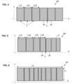
- the support device SP can provide a folding zone 3 between two adjacent panels.
- the folding zone 3 can allow a folding with an axis parallel to the transverse direction Y.
- the support device comprises N panels
- N-1 folding zones are provided, the folds possibly being substantially parallel to each other.
- the folding direction can be the same on all the folding zones or alternatively in the manner of an accordion, the two possibilities being illustrated below.
- picture 2 The amplitude of the possible folding of each folding zone can be symmetrical or not.
- the support device comprises a plurality of panels 2a, 2b contiguous and interconnected by a mechanical hinge (or articulation) acting as a folding zone 3.
- the articulation can be done along the axis X3 which is parallel in the transverse direction Y.
- the panel(s) 2 are integrated into a flexible sheath 6 (or envelope).
- the panels can be arranged one to the other along the longitudinal direction X.
- the panels can be contiguous as previously described or alternatively adjacent but not contiguous.
- the zones of the flexible sheath devoid of panels can then serve as bending zones 3.
- the flexible sheath 6 notably comprises an upper face and a lower face.
- the flexible sheath can be made of woven or non-woven fabric.
- the use of a polymer plastic film can be envisaged.
- the use of a fabric based on biodegradable natural fibers is also considered.
- the sheath 6 can be a continuous fabric or a mesh fabric or even a net. Locally, the thickness of the sheath is very small, the fabric or equivalent has considerable flexibility on bending; there can also be a certain longitudinal elasticity of the material.
- the flexible sheath 6 can form a single housing which receives the panel or the plurality of panels.
- the flexible sheath 6 comprises a plurality of housings 24, typically separated by a junction zone 26.
- the panels are inserted into the housings. According to one configuration, there is one panel per slot.
- the housings 24 can be arranged next to each other along the longitudinal direction (X), separated from each other by at least one junction zone 26, or even by a junction zone 26 between each pair of adjacent panels 2.
- the junction zone 26 acts as a folding zone 3, which can be orthogonal to the longitudinal direction.
- the upper face and the lower face of the flexible sheath 6 can be joined locally to thus form the housings. More precisely, a seam connects the upper face of the sheath to the lower face of the sheath in the junction zone 26. This ensures a spacing between the two adjacent panels which allows a folding of significant amplitude, or even almost a superposition of two adjacent panels (for example greater than 160°).
- the acquisition device 1 may further comprise a cover 8 enveloping at least the acquisition portion 1A.
- Said cover 8 can also perform the flexible sheath function or can be completely separate from the independent flexible sheath, as shown in figure 8 .
- the sheath is then housed inside the cover, so as to be positioned between the bed base elements and the sensor.
- the cover 8 comprises an upper face 8A, intended to be against the mattress and a lower face 8B, 8C, intended to be against the bed base elements.
- the sensor is then received inside the cover between the upper face and the lower face.
- the lower face comprises the sheath as described previously.
- a piece of fabric is arranged in three sections on a surface corresponding at least to the surface of the sensor.
- the upper face 8A is intended to cover at least the sensor 5.
- the lower face 8B is intended to be interposed between the panels of the support device SP and the bed base elements.
- the intermediate panel 8C is interposed between the sensor 5 and the panels of the support device.
- Connection seams 27 can be made on the outer edge.
- Intermediate seams 26 can be made to delimit and form housings receiving the panels 2.
- the figure 11 there may be multiple panels or pads in each slot.
- the wafers of the same housing can see their relative position change, for example for a complete snail-like winding of the acquisition portion.
- Each panel has in the examples a generally rectangular shape, of small thickness (for example between 1 and 3 mm).
- the dimensions of the panels along the transverse axis Y are substantially equivalent to the width of the sensor LY, so that substantially the entire sensor rests on the support device.
- substantially equivalent or substantially it is meant that said dimension of the panels is equal to at least 80%, even 90% or even 95%, of the width of the sensor LY.
- the width L2i is minimum in the middle and the panels are increasingly wide going towards the ends.
- plastic material can be used to make the rigid panels, for example PVC, polyethylene, polypropylene, ABS.
- a natural material such as wood is also possible.
- the acquisition device 1 may further comprise at least one attachment 4 (hereinafter referred to as attachment means) extending from the acquisition portion on either side of the acquisition portion.
- attachment means are presented as retention straps.
- the acquisition device 1 does not include the support device but includes the attachment 4.
- the fastening means are formed as strips of fabric or strips of fabric.
- the material can be a polymer plastic or a fabric of synthetic or natural fibers.
- the length of these strips L4 is sufficient to go around a slat, or even around a slat and twice the gap width L3 between the slats.
- the length of the strips L4 is between 30 cm and 60 cm.
- a Velcro hook zone on part of the strap.
- a velcro velvet area so that the strap can be attached to itself and its path allows at least one slat 7 to be rolled up.
- the strap makes a loop around a slat and comes back to attach to itself.
- the end of the strap can be attached to an intermediate portion of the strap (see right part picture 3 ); another possibility is that an end zone of the strap is attached to the cover (see left part picture 3 ).
- each of the straps is detachably associated with the cover 8.
- a Velcro TM type system can be used to attach the strap to an edge zone of the cover.
- laces may be provided as attachment means.
- a clothing belt-type locking buckle may be provided on each strap.
- the acquisition device may further comprise an electronic unit 9, which may be housed in a box 11.
- this electronic unit there may be provided a formatting and/or data processing circuit raw delivered by the sensor.
- a wireless communication coupler may also be provided.
- the acquisition device may further comprise a local power supply battery.
- the acquisition device may include a cable 96, in particular for the power supply of the device.
- the end of the cable is equipped with a 98 connector (eg micro-USB).
- the acquisition device can be equipped in its electronic unit with a wireless communication coupler 92 configured to transmit or even transmit and receive data in cooperation with a remote unit 94 (smartphone or remote server) .
- a wireless communication coupler 92 configured to transmit or even transmit and receive data in cooperation with a remote unit 94 (smartphone or remote server) .
- BlueTooth or BlueTooh Low Emission protocols, and/or Wi-Fi can be used.
- the box 11 can be housed next to the acquisition portion 1A, along the longitudinal direction X.
- the box can be mounted on the sheet forming the sensor 5.
- the cover 8 is then dimensioned so as to accommodate the box and the acquisition portion.
- the acquisition device can have a length of between 50cm and 1m, or even between 50 and 80cm, or even between 60 and 70cm.
- the acquisition device may have a width comprised between 10 and 30 cm, or even between 15 and 25 cm, or even between 18 and 23 cm.
- the cover defining the exterior of the acquisition device it has the same dimensions.
- the general shape of the acquisition device can be rectangular, with a thickness between 0.4cm and 2cm, or even between 0.4cm and 1cm, or even around 5mm.
- the mass of the acquisition device can be less than 500g.
Landscapes
- Health & Medical Sciences (AREA)
- Life Sciences & Earth Sciences (AREA)
- Surgery (AREA)
- Public Health (AREA)
- Animal Behavior & Ethology (AREA)
- Biophysics (AREA)
- Pathology (AREA)
- Engineering & Computer Science (AREA)
- Biomedical Technology (AREA)
- Heart & Thoracic Surgery (AREA)
- General Health & Medical Sciences (AREA)
- Molecular Biology (AREA)
- Veterinary Medicine (AREA)
- Physics & Mathematics (AREA)
- Medical Informatics (AREA)
- Physiology (AREA)
- Dentistry (AREA)
- Oral & Maxillofacial Surgery (AREA)
- Pulmonology (AREA)
- Cardiology (AREA)
- Mattresses And Other Support Structures For Chairs And Beds (AREA)
- Invalid Beds And Related Equipment (AREA)
- Measurement Of The Respiration, Hearing Ability, Form, And Blood Characteristics Of Living Organisms (AREA)
- Measuring And Recording Apparatus For Diagnosis (AREA)
Applications Claiming Priority (1)
| Application Number | Priority Date | Filing Date | Title |
|---|---|---|---|
| FR2111494A FR3128621A1 (fr) | 2021-10-28 | 2021-10-28 | Appareil de detection pour literie |
Publications (1)
| Publication Number | Publication Date |
|---|---|
| EP4173566A1 true EP4173566A1 (de) | 2023-05-03 |
Family
ID=80225587
Family Applications (1)
| Application Number | Title | Priority Date | Filing Date |
|---|---|---|---|
| EP22198425.5A Pending EP4173566A1 (de) | 2021-10-28 | 2022-09-28 | Bettzeug-detektionsvorrichtung |
Country Status (3)
| Country | Link |
|---|---|
| US (1) | US20230148760A1 (de) |
| EP (1) | EP4173566A1 (de) |
| FR (1) | FR3128621A1 (de) |
Citations (5)
| Publication number | Priority date | Publication date | Assignee | Title |
|---|---|---|---|---|
| US4320766A (en) * | 1979-03-13 | 1982-03-23 | Instrumentarium Oy | Apparatus in medicine for the monitoring and or recording of the body movements of a person on a bed, for instance of a patient |
| EP2873368A1 (de) | 2013-11-18 | 2015-05-20 | Withings | Sensorvorrichtung für Betten zur Überwachung des Schlafs |
| EP3508187A1 (de) | 2018-01-08 | 2019-07-10 | Withings | Vorrichtung und zugehörige verfahren zur erkennung einer variablen kraft |
| WO2021008737A1 (en) * | 2019-07-12 | 2021-01-21 | Withings | Sleep sensing and monitoring device |
| EP3828598A1 (de) * | 2018-09-19 | 2021-06-02 | Mitsui Chemicals, Inc. | Vorrichtung zur detektion eines menschlichen körpers, bettvorrichtung und system zur erfassung eines menschlichen körpers |
-
2021
- 2021-10-28 FR FR2111494A patent/FR3128621A1/fr active Pending
-
2022
- 2022-09-28 EP EP22198425.5A patent/EP4173566A1/de active Pending
- 2022-10-05 US US17/960,525 patent/US20230148760A1/en active Pending
Patent Citations (5)
| Publication number | Priority date | Publication date | Assignee | Title |
|---|---|---|---|---|
| US4320766A (en) * | 1979-03-13 | 1982-03-23 | Instrumentarium Oy | Apparatus in medicine for the monitoring and or recording of the body movements of a person on a bed, for instance of a patient |
| EP2873368A1 (de) | 2013-11-18 | 2015-05-20 | Withings | Sensorvorrichtung für Betten zur Überwachung des Schlafs |
| EP3508187A1 (de) | 2018-01-08 | 2019-07-10 | Withings | Vorrichtung und zugehörige verfahren zur erkennung einer variablen kraft |
| EP3828598A1 (de) * | 2018-09-19 | 2021-06-02 | Mitsui Chemicals, Inc. | Vorrichtung zur detektion eines menschlichen körpers, bettvorrichtung und system zur erfassung eines menschlichen körpers |
| WO2021008737A1 (en) * | 2019-07-12 | 2021-01-21 | Withings | Sleep sensing and monitoring device |
Also Published As
| Publication number | Publication date |
|---|---|
| FR3128621A1 (fr) | 2023-05-05 |
| US20230148760A1 (en) | 2023-05-18 |
Similar Documents
| Publication | Publication Date | Title |
|---|---|---|
| EP2873368B1 (de) | Sensorvorrichtung für Betten zur Überwachung des Schlafs | |
| FR2861570A1 (fr) | Feuille de capteur | |
| FR2543420A1 (fr) | Dispositif de soulagement et de confort de posture, comportant deux coussins solidarisables | |
| CA2972637A1 (fr) | Ceinture pour femme enceinte | |
| CH625689A5 (de) | ||
| BE1009689A6 (fr) | Coussin de relaxation. | |
| EP4173566A1 (de) | Bettzeug-detektionsvorrichtung | |
| FR2474435A1 (fr) | Appareil de sauvetage du type enveloppe | |
| CH673937A5 (de) | ||
| WO2022079393A1 (fr) | Dispositif conçu pour equiper un masque respiratoire et collecter les donnees respiratoires d'un porteur | |
| FR2559056A1 (fr) | Dispositif de transfert destine notamment au transfert de patients en milieu hospitalier et ensemble comportant un tel dispositif | |
| EP2552283B1 (de) | Klappbare und transportierbare vorrichtung zum halten der sitzenden stellung | |
| WO2004086325A2 (fr) | Dispositif de mesure d’au moins une information physiologique a membrane souple, module capteur et procede de fabrication correspondants | |
| FR2461492A1 (fr) | Siege pour leve-malade | |
| FR3074677A1 (fr) | Ensemble de vetements et dispositifs de mesures de parametres de posture corporelle d'un individu | |
| EP1067849B1 (de) | Gürtel für kochhose | |
| EP3302375B1 (de) | Hilfe zur haltungsverbesserung | |
| FR2773692A1 (fr) | Procede et appui-tete lateral amovible pour maintenir lateralement la tete d'une personne assise dans un fauteuil | |
| FR2612755A1 (fr) | Canape lit | |
| EP0554428A1 (de) | In ein reisebett umwandelbarer rucksack | |
| CN212995506U (zh) | 一种具有人体工程学弧度的坐垫 | |
| FR2967659A1 (fr) | Dispositif pour dispenser un fluide a pression sensiblement constante | |
| FR2624711A1 (fr) | Dispositif portable pour rigidifier un ensemble sommier/matelas d'un lit | |
| WO2023208839A1 (fr) | Elément de literie à maintien évolué | |
| FR3127808A1 (fr) | Dispositif de détection de la posture d’un individu en position assise, coussin d’assise et système de détection incluant un tel dispositif |
Legal Events
| Date | Code | Title | Description |
|---|---|---|---|
| PUAI | Public reference made under article 153(3) epc to a published international application that has entered the european phase |
Free format text: ORIGINAL CODE: 0009012 |
|
| STAA | Information on the status of an ep patent application or granted ep patent |
Free format text: STATUS: REQUEST FOR EXAMINATION WAS MADE |
|
| 17P | Request for examination filed |
Effective date: 20220928 |
|
| AK | Designated contracting states |
Kind code of ref document: A1 Designated state(s): AL AT BE BG CH CY CZ DE DK EE ES FI FR GB GR HR HU IE IS IT LI LT LU LV MC MK MT NL NO PL PT RO RS SE SI SK SM TR |