EP4173545B1 - Shoe care apparatus - Google Patents
Shoe care apparatus Download PDFInfo
- Publication number
- EP4173545B1 EP4173545B1 EP21858465.4A EP21858465A EP4173545B1 EP 4173545 B1 EP4173545 B1 EP 4173545B1 EP 21858465 A EP21858465 A EP 21858465A EP 4173545 B1 EP4173545 B1 EP 4173545B1
- Authority
- EP
- European Patent Office
- Prior art keywords
- supporter
- rail
- supply
- shutter
- door
- Prior art date
- Legal status (The legal status is an assumption and is not a legal conclusion. Google has not performed a legal analysis and makes no representation as to the accuracy of the status listed.)
- Active
Links
Images








Classifications
-
- A—HUMAN NECESSITIES
- A47—FURNITURE; DOMESTIC ARTICLES OR APPLIANCES; COFFEE MILLS; SPICE MILLS; SUCTION CLEANERS IN GENERAL
- A47L—DOMESTIC WASHING OR CLEANING; SUCTION CLEANERS IN GENERAL
- A47L23/00—Cleaning footwear
- A47L23/02—Shoe-cleaning machines, with or without applicators for shoe polish
-
- A—HUMAN NECESSITIES
- A43—FOOTWEAR
- A43D—MACHINES, TOOLS, EQUIPMENT OR METHODS FOR MANUFACTURING OR REPAIRING FOOTWEAR
- A43D3/00—Lasts
- A43D3/14—Stretching or spreading lasts; Boot-trees; Fillers; Devices for maintaining the shape of the shoe
- A43D3/1408—Devices for heating or drying shoes
-
- A—HUMAN NECESSITIES
- A47—FURNITURE; DOMESTIC ARTICLES OR APPLIANCES; COFFEE MILLS; SPICE MILLS; SUCTION CLEANERS IN GENERAL
- A47L—DOMESTIC WASHING OR CLEANING; SUCTION CLEANERS IN GENERAL
- A47L23/00—Cleaning footwear
- A47L23/18—Devices for holding footwear during cleaning or shining; Holding devices with stretching effect
-
- A—HUMAN NECESSITIES
- A47—FURNITURE; DOMESTIC ARTICLES OR APPLIANCES; COFFEE MILLS; SPICE MILLS; SUCTION CLEANERS IN GENERAL
- A47L—DOMESTIC WASHING OR CLEANING; SUCTION CLEANERS IN GENERAL
- A47L23/00—Cleaning footwear
- A47L23/20—Devices or implements for drying footwear, also with heating arrangements
-
- A—HUMAN NECESSITIES
- A47—FURNITURE; DOMESTIC ARTICLES OR APPLIANCES; COFFEE MILLS; SPICE MILLS; SUCTION CLEANERS IN GENERAL
- A47L—DOMESTIC WASHING OR CLEANING; SUCTION CLEANERS IN GENERAL
- A47L23/00—Cleaning footwear
- A47L23/20—Devices or implements for drying footwear, also with heating arrangements
- A47L23/205—Devices or implements for drying footwear, also with heating arrangements with heating arrangements
-
- F—MECHANICAL ENGINEERING; LIGHTING; HEATING; WEAPONS; BLASTING
- F26—DRYING
- F26B—DRYING SOLID MATERIALS OR OBJECTS BY REMOVING LIQUID THEREFROM
- F26B21/00—Arrangements for supplying or controlling air or other gases for drying solid materials or objects
- F26B21/006—Arrangements for supplying or controlling air or other gases for drying solid materials or objects with the air or gases passing through hollow spaces or cores within the materials or objects to be dried, e.g. tubes, pipes or bottles
- F26B21/008—Arrangements for supplying or controlling air or other gases for drying solid materials or objects with the air or gases passing through hollow spaces or cores within the materials or objects to be dried, e.g. tubes, pipes or bottles the objects being flexible, e.g. inflatable tubes or sausage casings
-
- F—MECHANICAL ENGINEERING; LIGHTING; HEATING; WEAPONS; BLASTING
- F26—DRYING
- F26B—DRYING SOLID MATERIALS OR OBJECTS BY REMOVING LIQUID THEREFROM
- F26B21/00—Arrangements for supplying or controlling air or other gases for drying solid materials or objects
- F26B21/20—Circulating air or gases in closed cycles, e.g. wholly within the drying enclosure
- F26B21/202—Circulating air or gases in closed cycles, e.g. wholly within the drying enclosure with means for changing the flow pattern, e.g. by reversing gas flow or by moving the materials or objects through subsequent compartments, at least two of which have a different flow direction
- F26B21/208—Circulating air or gases in closed cycles, e.g. wholly within the drying enclosure with means for changing the flow pattern, e.g. by reversing gas flow or by moving the materials or objects through subsequent compartments, at least two of which have a different flow direction by air valves, movable baffles or nozzle arrangements
-
- F—MECHANICAL ENGINEERING; LIGHTING; HEATING; WEAPONS; BLASTING
- F26—DRYING
- F26B—DRYING SOLID MATERIALS OR OBJECTS BY REMOVING LIQUID THEREFROM
- F26B21/00—Arrangements for supplying or controlling air or other gases for drying solid materials or objects
- F26B21/30—Controlling, e.g. regulating, parameters of gas supply
-
- F—MECHANICAL ENGINEERING; LIGHTING; HEATING; WEAPONS; BLASTING
- F26—DRYING
- F26B—DRYING SOLID MATERIALS OR OBJECTS BY REMOVING LIQUID THEREFROM
- F26B21/00—Arrangements for supplying or controlling air or other gases for drying solid materials or objects
- F26B21/30—Controlling, e.g. regulating, parameters of gas supply
- F26B21/33—Humidity
- F26B21/333—Humidity by condensing the moisture in the drying medium, which may be recycled, e.g. using a heat pump cycle
Definitions
- the present invention relates to a shoe care apparatus, and more particularly, to a shoe care apparatus including a blowing flow path.
- Shoes are worn on the feet when walking or exercising, and the shoes may be contaminated by soil or dirt, and may also be contaminated by sweat. Therefore, it is required to periodically wash the shoes for the comfortable use.
- a degree of contamination is typically greater than that of clothes and thus it is difficult to wash the shoes and the clothes together.
- shoes include various parts such as an upper, a midsole, an outsole, an insole, a tongue, a heel cup, and a heeltap.
- various materials may be applied to each part.
- a relatively hard material may be applied to a midsole, an outsole, and/or a heel cup
- a relatively soft material may be applied to an insole and a heel tab.
- Shoes have a relatively complex structure, and thus it is not easy to care for the shoes with a conventional clothes care apparatus.
- JP S59 204 B2 discloses a shoe care cabinet having a valve arrangement for opening and closing a supply port to supply air to shoes in the cabinet.
- the present invention is directed to providing a shoe care apparatus capable of preventing foreign substances from entering a blow duct.
- the present invention is directed to providing a shoe care apparatus capable of having an increased usability.
- a shoe care apparatus may open and close a blow duct depending on whether a supporter is mounted or not, thereby preventing foreign substances from entering the blow duct.
- a shoe care apparatus may automatically open and close a blow duct depending on whether a supporter is mounted, and thus the convenience of use may be increased.
- shoe care apparatus 1 for caring for shoes is described as an example, but the shoe care apparatus 1 according to one embodiment of the present invention may be used to care for clothes and/or miscellaneous goods other than shoes.
- a direction along the X-axis may be defined as a left and right direction
- a direction along the Y-axis may be defined as a front and rear direction
- a direction along the-Z axis may be defined as an up and down direction.
- a shoe care apparatus 1 may include a cabinet 10 forming an exterior and a cabinet door 20 rotatably coupled to the cabinet 10.
- the cabinet 10 may have a rectangular parallelepiped shape with an open front surface.
- a cabinet opening 10a may be formed in an open front surface of the cabinet 10.
- the cabinet door 20 may be rotatably coupled to the cabinet 10 to open and close a care chamber 30 formed inside the cabinet 10.
- the cabinet door 20 may be coupled to the cabinet 10 through a hinge 23.
- the cabinet door 20 may include a hanger 21 arranged on one surface that faces the inside of the care chamber when the cabinet door 20 closes the care chamber 30. At least one hanger 21 may be provided.
- the hanger 21 may be provided to allow a supporter 50, which is described later, to be hung thereon, thereby easily storing the supporter 50.
- the use of the hanger 21 is not limited thereto, and may be used to store other components.
- the cabinet door 20 may further include an input device 22 arranged on a front surface of the shoe care apparatus 1.
- a user can set various care courses through the input device 22 based on the type of shoes for which to be cared.
- the cabinet 10 may include an outer case 11 and an inner case 12 disposed inside the outer case 11.
- the inner case 12 may form the care chamber 30.
- the care chamber 30 may be provided to accommodate a plurality of shoes.
- a machine room 40 in which a heat exchanger 47 for dehumidifying or heating air inside the care chamber 30 is arranged, may be provided in the cabinet 10.
- the supporter 50 configured to support shoes may be provided inside the care chamber 30.
- the supporter 50 may be installed on one side of the care chamber 30.
- FIGS. 2 and 3 illustrate that the supporter 50 is located on the right side of the care chamber 30, but the position of the supporter 50 is not limited thereto.
- the supporter 50 may be located on the left side or on the rear inner side of the care chamber 30.
- the supporter 50 may be detachably provided in the cabinet 10. At least one supporter 50 may be provided.
- the supporter 50 may be formed in a shape that may be inserted into a shoe.
- a drain pan 48 detachably provided to the cabinet 10 may be installed at a lower portion of the cabinet 10.
- the drain pan 48 may be disposed under the care chamber 30.
- the drain pan 48 may be provided to easily collect condensed water generated by the heat exchanger 47.
- the drain pan 48 may be provided under the machine room 40.
- the machine room 40 may be located at the lower end of the cabinet 10.
- the machine room 40 may be provided under the care chamber 30.
- the heat exchanger 47 may be configured to dehumidify and/or heat the air inside the care chamber 30 as needed.
- the heat exchanger 47 may be configured to supply hot dry air to the inside of the care chamber 30.
- the heat exchanger 47 may include an evaporator 42 and a condenser 43 through which a refrigerant circulates.
- the heat exchanger 47 may be configured to dehumidify and/or heat the air.
- the evaporator 42 may condense and remove moisture from the surrounding air.
- the refrigerant passing through the evaporator 42 becomes a high-temperature and high-pressure state while passing through the compressor 41.
- the condenser 43 may heat the surrounding air by releasing latent heat toward the surrounding air.
- Air introduced into the machine room 40 through a fan 44 may be dehumidified and heated by passing through the evaporator 42 and the condenser 43.
- the fan 44 may be provided as a centrifugal fan that sucks air in a rotation axis direction and discharges air in a radial direction.
- the type of fan 44 is not limited thereto, and may be provided as an axial flow fan or a mixed flow fan.
- connection flow path 46a through which air passing through the evaporator 42, the condenser 43, and the blower fan 44 flows, may be formed in the machine room 40.
- the connection flow path 46a may be formed by a connection duct 46.
- the connection duct 46 may communicate with the care chamber 30.
- the shoe care apparatus 1 may further include a water tank (not shown), a steam generator (not shown) configured to generate steam by receiving water from the water tank, and a steam spraying device (not shown) configured to receive steam from the steam generator and spray the steam.
- a water tank not shown
- a steam generator not shown
- a steam spraying device not shown
- the water tank may be disposed under the care chamber 30. Water in the water tank may be supplied to the steam generator and used to form steam. The water tank may be installed to be detached from the cabinet 10 to facilitate water replenishment.
- the steam generator may be disposed in the machine room 40.
- the steam generator may generate steam and guide the steam to the steam spraying device.
- the steam generator may be connected to the steam spraying device through a steam supply pipe (not shown).
- the shoe care apparatus 1 may further include a deodorizer 45.
- the deodorizer 45 may be disposed within the machine room 40.
- the deodorizer 45 may be disposed in the connection duct 46 to remove odors from the air passing through the care chamber 30.
- the deodorizer 45 is illustrated as being located on the left side of the blower fan 44, but is not limited thereto. Alternatively, the deodorizer 45 may be located on the right side of the blower fan 44.
- the deodorizer 45 may include a deodorizing filter 45a and a germicidal lamp 45b.
- the deodorizing filter 45a may include a ceramic filter.
- the germicidal lamp 45b may include an ultraviolet lamp.
- the deodorizing filter is not limited thereto, and the deodorizing filter 45a may include various filters as long as a filter is configured to remove odors from the air, and the germicidal lamp 45b may also include various devices as long as a device is configured to sterilize germs.
- At least one plate 90 may be provided in the care chamber 30.
- the plate 90 may be provided to hold shoes.
- a supply port 60 and the supporter 50 may be positioned adjacent to the plate 90.
- the plate 90 may include a duct plate 95.
- the duct plate 95 may include an internal flow path 96 as shown in FIG. 3 .
- the heated air passing through the internal flow path 96 may be sprayed toward shoes from a spray port 95a of the duct plate 95 and a spray port 97a of a circular duct 97, respectively.
- the heated air may pass through the internal flow path 96 and be discharged to the care chamber 30 through a plate outlet 98.
- the supply port 60 and a return port 31 may be provided in the care chamber 30.
- the supply port 60 may be located on a side wall of the inner case 12. Particularly, the supply port 60 may be formed on the left surface, in which the supporter 50 is located, of the care chamber 30. However, the position of the supply port 60 is not limited thereto, and may be formed on the right side of the care chamber 30 as long as the position corresponds to the position of the supporter 50. At least one supply port 60 may be formed, and shoes may be dried by supplying heated air into the care chamber 30.
- the shape of the supply port 60 may be approximately circular. However, the shape of the supply port 60 is not limited thereto, and as long as the supply port is provided to supply heated air into the care chamber 30 so as to dry shoes, the support port 60 may have various shapes such as squares and polygons.
- the return port 31 may be disposed at the front end of the bottom surface of the care chamber 30. However, the position of the return port 31 is not limited thereto, and may also be disposed at the rear end and/or the side end of the bottom surface of the care chamber 30. Air drying shoes in the care chamber 30 may be returned to the connection duct 46 to be described later through the return port 31. A return hole 31a and a return grille 31b may be provided in the return port 31.
- connection duct 46 may be provided to communicate with a supply duct 70 and the return port 31 of the care chamber 30. One end of the connection duct 46 may communicate with the supply duct 70 and the other end may communicate with the return port 31.
- the air introduced through the return port 31 may be dehumidified and/or heated while passing through the connection duct 46, and then the dehumidified and/or heated air may be discharged back to the care chamber 30 through the supply duct 70 and the supply port 60.
- the supply duct 70 may be provided to extend vertically between the outer case 11 and the inner case 12 of the cabinet 10.
- the supply duct 70 may be located on one side, to which the supporter 50 is mounted, of the cabinet 10.
- One end of the supply duct 70 may communicate with the connection duct 46.
- the supply duct 70 may be provided to communicate with the supply port 60.
- the supply duct 70 may form a guide flow path 71 provided to guide heated air to the supply port 60.
- FIG. 4 is an enlarged view of part B of FIG. 2 .
- FIG. 5 is an exploded view of the supporter rail of FIG. 4 .
- FIG. 6 is a view illustrating a state in which a supporter of FIG. 2 starts to be mounted on the supporter rail.
- FIG. 7 is a view illustrating a state in which the supporter of FIG. 6 opens a supply door while being mounted on the supporter rail.
- FIG. 8 is a view illustrating a state in which the supporter of FIG. 7 completely opens the supply door while being completely mounted on the supporter rail.
- the supporter rail 100 may include a rail body 101 fixed to the inner case 12.
- the rail body 101 may include a fixer 105 coupled to a fixing member (not shown) and fixed to the inner case 12.
- a guide rail 103 may be formed on the supporter rail 100 to guide the supporter 50 when the supporter 50 is mounted on or separated from the supporter rail 100.
- the guide rail 103 may protrude from the supporter supporting member 102.
- the guide rail 103 may extend along a direction in which the supporter 50 is mounted on the supporter rail 100 or a direction in which the supporter 50 is separated from the supporter rail 100.
- the supporter rail 100 may include the supply door 106.
- the supply door 106 may be rotatably coupled to the rail body 101.
- the supply door 106 may include a door shaft 108 rotatably coupled to the rail body 101.
- the supply door 106 may be configured to open and close the rail opening 101a.
- the supporter rail 100 may include an elastic body 109 provided to elastically bias the supply door 106 to a direction of closing the rail opening 101a.
- the elastic body 109 may press the supply door 106 to the direction of closing the rail opening 101a.
- the elastic body 109 may be provided as a spring.
- the trigger 107 may include a first member 107a in which a pressure by the supporter 50 starts when the supporter 50 is mounted.
- the first member 107a may be more inclined, with respect to a direction away from the supply door 106, as the supporter is along a direction of being mounted to the supporter rail. Accordingly, when the supporter 50 is mounted on the supporter rail 100, the supply door 106 may be gradually opened as the supporter 50 presses the first member 107a of the trigger 107 and moves.
- the trigger 107 may include a second member 107b that extends further from the supply door 106 than the first member 107a.
- the second member 107b may be disposed to be pressed by the supporter 50 when the supporter 50 is completely mounted to the supporter rail 100.
- the second member 107b of the trigger 107 may be provided to further open the supply door 106 than when the supporter 50 presses the first member 107a.
- FIGS. 6 to 8 An operation of the supply door 106 according to one embodiment of the present invention will be described with reference to FIGS. 6 to 8 .
- the supporter 50 may include a guide 52 into which the guide rail 103 is inserted.
- the guide 52 may include a member extending along a direction in which the supporter 50 is mounted on the supporter rail 100.
- the supporter 50 may include a pressing member 51 provided to press the trigger 107.
- the pressing member 51 may be inserted into the supporter supporting member 102.
- the pressing member 51 presses the first member 107a of the trigger 107. Accordingly, the supply door 106 is rotated by a predetermined angle and opens the rail opening 101a.
- the pressing member 51 presses the second member 107b of the trigger 107. Accordingly, the supply door 106 is further rotated by a predetermined angle and completely opens the rail opening 101a. Accordingly, the supply port 60 may be opened.
- the pressing member 51 releases the pressure of the trigger 107.
- the elastic body 109 applies an elastic force to the supply door 106 to the direction in which the supply door 106 closes the rail opening 101a. Accordingly, the supply door 106 is rotated to a position to close the rail opening 101a as the supporter 50 is separated from the supporter rail 100. Therefore, the supply port 60 may be closed.
- the supporter rail 100 may discharge the air, which is guided through the guide flow path 71, to the care chamber 30 through the supporter 50 when the supporter 50 is mounted. Further, the supporter rail 100 may prevent foreign substances from entering the guide flow path 71 when the supporter 50 is separated.
- FIG. 9 is an exploded view of a supporter rail according to another embodiment of the present invention.
- a supporter rail 200 according to another embodiment of the present invention will be described with reference to FIG. 9 .
- the same reference numerals are assigned to the same components as those of the supporter rail 100 shown in FIGS. 4 and 5 , and detailed descriptions thereof may be omitted.
- the supporter rail 200 may include a supply door 206 rotatably coupled to the rail body 101.
- the supply door 206 may include a door shaft 208 rotatably coupled to the rail body 101.
- the supply door 206 may include a trigger 207 provided to be pressed by the supporter 50 so as to gradually open the supply door 206.
- the trigger 207 may include a first member 207a primarily opening the supply door 206 and a second member 207b secondarily opening the supply door 206.
- the supply door 206 may include a weight member 209.
- the weight member 209 may be located at a lower end of the supply door 206.
- the weight member 209 may be provided to rotate the supply door 206 to a direction of closing the rail opening 101a when the supporter 50 is separated from the supporter rail 200. Accordingly, the supply port 60 may be closed.
- the weight member 209 may be provided to have a heavier weight than other parts of the supply door 206.
- the supporter rail 200 may discharge the air, which is guided through the guide flow path 71, to the care chamber 30 through the supporter 50 when the supporter 50 is mounted. Further, the supporter rail 200 may prevent foreign substances from entering the guide flow path 71 when the supporter 50 is separated.
- FIG. 10 is a view of a supporter rail according to still another embodiment of the present invention.
- FIG. 11 is an exploded view of the supporter rail of FIG. 10 .
- FIG. 12 is a view illustrating a state in which the supporter of FIG. 10 starts to be mounted on the supporter rail.
- FIG. 13 is a view illustrating a state in which the supporter of FIG. 12 opens a first shutter of a supply door while being mounted on the supporter rail.
- FIG. 14 is a view illustrating a state in which the supporter of FIG. 13 completely opens a second shutter of the supply door while being completely mounted on the supporter rail.
- FIG. 15 is a view illustrating a state in which the supporter of FIG.
- FIG. 16 is a view illustrating a state in which the supporter of FIG. 15 is moved to a direction, in which the second shutter is closed, as being moved to the direction, in which the first shutter of the supporter rail is closed while being separated from the supporter rail.
- a supporter rail 300 according to still another embodiment of the present invention will be described with reference to FIGS. 10 to 16 .
- the same reference numerals are assigned to the same components as those of the embodiment shown in FIGS. 4 and 5 , and detailed descriptions thereof may be omitted.
- the supporter rail 300 may include a supply door 306 configured to open and close the rail opening 101a of the rail body 101.
- the supply door 306 may be slidably coupled to the rail body 101.
- the rail body 101 may include a door supporting member 309 provided to slidably support the supply door 306.
- the supply door 306 may include a first shutter 310 and a second shutter 320.
- the first shutter 310 may be slidably coupled to the second shutter 320.
- the first shutter 310 may include a first shutter body 311 and a lever 312 protruding from the first shutter body 311 to interfere with the supporter 50 when the supporter 50 is coupled.
- the lever 312 may penetrate the rail opening 101a and extend to a space between the supporter supporting member 102.
- the second shutter 320 may be slidably coupled to the first shutter 310.
- the second shutter 320 may include the second shutter body 321.
Landscapes
- Engineering & Computer Science (AREA)
- Mechanical Engineering (AREA)
- General Engineering & Computer Science (AREA)
- Drying Of Solid Materials (AREA)
- Support Devices For Sliding Doors (AREA)
- Drawers Of Furniture (AREA)
Description
- The present invention relates to a shoe care apparatus, and more particularly, to a shoe care apparatus including a blowing flow path.
- Shoes are worn on the feet when walking or exercising, and the shoes may be contaminated by soil or dirt, and may also be contaminated by sweat. Therefore, it is required to periodically wash the shoes for the comfortable use. However, because shoes include a part that directly touches the floor, a degree of contamination is typically greater than that of clothes and thus it is difficult to wash the shoes and the clothes together.
- In addition, unlike general clothes, shoes include various parts such as an upper, a midsole, an outsole, an insole, a tongue, a heel cup, and a heeltap. Further, according to the purpose of each part, various materials may be applied to each part. For example, a relatively hard material may be applied to a midsole, an outsole, and/or a heel cup, and a relatively soft material may be applied to an insole and a heel tab. Shoes have a relatively complex structure, and thus it is not easy to care for the shoes with a conventional clothes care apparatus.
- In addition, as the size of the resell market for limited edition shoes has recently increased, consumers' interest in the limited-edition shoes is increased, and there is a growing need of a device for easy care for the limited-edition shoes.
-
JP S59 204 B2 - The present invention is directed to providing a shoe care apparatus capable of preventing foreign substances from entering a blow duct.
- Further, the present invention is directed to providing a shoe care apparatus capable of having an increased usability.
- According to the invention, there is provided a shoe care apparatus according to
claim 1. Preferred features are set out in the dependent claims. - A shoe care apparatus may open and close a blow duct depending on whether a supporter is mounted or not, thereby preventing foreign substances from entering the blow duct.
- A shoe care apparatus may automatically open and close a blow duct depending on whether a supporter is mounted, and thus the convenience of use may be increased.
-
-
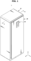
FIG. 1 is a diagram illustrating a shoe care apparatus according to an embodiment of the invention. -
FIG. 2 is a view illustrating a state in which a cabinet door of the shoe care apparatus shown inFIG. 1 is opened. -
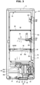
FIG. 3 is a sectional view taken along line A-A' ofFIG. 1 . -
FIG. 4 is an enlarged view of part B ofFIG. 2 . -
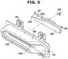
FIG. 5 is an exploded view of a supporter rail ofFIG. 4 . -
FIG. 6 is a view illustrating a state in which a supporter ofFIG. 2 starts to be mounted on the supporter rail. -
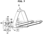
FIG. 7 is a view illustrating a state in which the supporter ofFIG. 6 opens a supply door while being mounted on the supporter rail. -
FIG. 8 is a view illustrating a state in which the supporter ofFIG. 7 completely opens the supply door while being completely mounted on the supporter rail. -
FIG. 9 is an exploded view of a supporter rail according to another embodiment of the invention. -
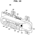
FIG. 10 is a view of a supporter rail according to still another embodiment of the invention. -
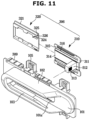
FIG. 11 is an exploded view of the supporter rail ofFIG. 10 . -
FIG. 12 is a view illustrating a state in which a supporter ofFIG. 10 starts to be mounted on the supporter rail. -
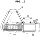
FIG. 13 is a view illustrating a state in which the supporter ofFIG. 12 opens a first shutter of a supply door while being mounted on the supporter rail. -
FIG. 14 is a view illustrating a state in which the supporter ofFIG. 13 completely opens a second shutter of the supply door while being completely mounted on the supporter rail. -
FIG. 15 is a view illustrating a state in which the supporter ofFIG. 14 is moved to a direction, in which the first shutter of the supporter rail is closed, while being separated from the supporter rail. -
FIG. 16 is a view illustrating a state in which the supporter ofFIG. 15 is moved to a direction, in which the second shutter is closed, as being moved to the direction, in which the first shutter of the supporter rail is closed while being separated from the supporter rail. -
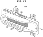
FIG. 17 is a view of a supporter rail according to still another embodiment of the invention. - Embodiments described in the disclosure and configurations shown in the drawings are merely examples of the embodiments of the invention.
- In addition, the same reference numerals or signs shown in the drawings of the disclosure indicate elements or components performing substantially the same function. Shapes and sizes of elements in the drawings may be exaggerated for clear description.
- Also, the terms used herein are used to describe the embodiments and are not intended to limit and / or restrict the invention, which is defined by the claims. The singular forms "a," "an" and "the" are intended to include the plural forms as well, unless the context clearly indicates otherwise. In this disclosure, the terms "including", "having", and the like are used to specify features, numbers, steps, operations, elements, components, or combinations thereof, but do not preclude the presence or addition of one or more of the features, elements, steps, operations, elements, components, or combinations thereof.
- It will be understood that, although the terms first, second, third, etc., may be used herein to describe various elements, but elements are not limited by these terms. These terms are only used to distinguish one element from another element. For example, without departing from the scope of the invention, a first element may be termed as a second element, and a second element may be termed as a first element. The term of "and / or" includes a plurality of combinations of relevant items or any one item among a plurality of relevant items.
- The invention will be described more fully hereinafter with reference to the accompanying drawings. For convenience of description, a shoe care apparatus for caring for shoes is described as an example, but the
shoe care apparatus 1 according to one embodiment of the present invention may be used to care for clothes and/or miscellaneous goods other than shoes. -
FIG. 1 is a diagram illustrating a shoe care apparatus according to one embodiment of the present invention.FIG. 2 is a view illustrating a state in which a cabinet door of the shoe care apparatus shown inFIG. 1 is opened.FIG. 3 is a sectional view taken along line A-A' ofFIG. 1 . - Referring to
FIG. 1 , a direction along the X-axis may be defined as a left and right direction, a direction along the Y-axis may be defined as a front and rear direction, and a direction along the-Z axis may be defined as an up and down direction. - Referring to
FIGS. 1 to 3 , ashoe care apparatus 1 according to one embodiment of the present invention may include acabinet 10 forming an exterior and acabinet door 20 rotatably coupled to thecabinet 10. - The
cabinet 10 may have a rectangular parallelepiped shape with an open front surface. A cabinet opening 10a may be formed in an open front surface of thecabinet 10. Thecabinet door 20 may be rotatably coupled to thecabinet 10 to open and close acare chamber 30 formed inside thecabinet 10. Thecabinet door 20 may be coupled to thecabinet 10 through ahinge 23. - The
cabinet door 20 may include ahanger 21 arranged on one surface that faces the inside of the care chamber when thecabinet door 20 closes thecare chamber 30. At least onehanger 21 may be provided. Thehanger 21 may be provided to allow asupporter 50, which is described later, to be hung thereon, thereby easily storing thesupporter 50. The use of thehanger 21 is not limited thereto, and may be used to store other components. - The
cabinet door 20 may further include aninput device 22 arranged on a front surface of theshoe care apparatus 1. A user can set various care courses through theinput device 22 based on the type of shoes for which to be cared. - The
cabinet 10 may include anouter case 11 and aninner case 12 disposed inside theouter case 11. Theinner case 12 may form thecare chamber 30. Thecare chamber 30 may be provided to accommodate a plurality of shoes. - A
machine room 40, in which aheat exchanger 47 for dehumidifying or heating air inside thecare chamber 30 is arranged, may be provided in thecabinet 10. - The
supporter 50 configured to support shoes may be provided inside thecare chamber 30. Thesupporter 50 may be installed on one side of thecare chamber 30.FIGS. 2 and3 illustrate that thesupporter 50 is located on the right side of thecare chamber 30, but the position of thesupporter 50 is not limited thereto. Alternatively, thesupporter 50 may be located on the left side or on the rear inner side of thecare chamber 30. Thesupporter 50 may be detachably provided in thecabinet 10. At least onesupporter 50 may be provided. Thesupporter 50 may be formed in a shape that may be inserted into a shoe. - A
drain pan 48 detachably provided to thecabinet 10 may be installed at a lower portion of thecabinet 10. Thedrain pan 48 may be disposed under thecare chamber 30. Thedrain pan 48 may be provided to easily collect condensed water generated by theheat exchanger 47. - The
drain pan 48 may be provided under themachine room 40. Themachine room 40 may be located at the lower end of thecabinet 10. Themachine room 40 may be provided under thecare chamber 30. - The
heat exchanger 47 may be configured to dehumidify and/or heat the air inside thecare chamber 30 as needed. - The
heat exchanger 47 may be configured to supply hot dry air to the inside of thecare chamber 30. Theheat exchanger 47 may include anevaporator 42 and acondenser 43 through which a refrigerant circulates. Theheat exchanger 47 may be configured to dehumidify and/or heat the air. - As the refrigerant passing through the
evaporator 42 absorbs latent heat from the surrounding air, theevaporator 42 may condense and remove moisture from the surrounding air. The refrigerant passing through theevaporator 42 becomes a high-temperature and high-pressure state while passing through thecompressor 41. As the high-temperature and high-pressure refrigerant is condensed by passing through thecondenser 43, thecondenser 43 may heat the surrounding air by releasing latent heat toward the surrounding air. Air introduced into themachine room 40 through afan 44 may be dehumidified and heated by passing through theevaporator 42 and thecondenser 43. - The
fan 44 may be provided as a centrifugal fan that sucks air in a rotation axis direction and discharges air in a radial direction. However, the type offan 44 is not limited thereto, and may be provided as an axial flow fan or a mixed flow fan. - A
connection flow path 46a, through which air passing through theevaporator 42, thecondenser 43, and theblower fan 44 flows, may be formed in themachine room 40. Theconnection flow path 46a may be formed by aconnection duct 46. Theconnection duct 46 may communicate with thecare chamber 30. - The
shoe care apparatus 1 may further include a water tank (not shown), a steam generator (not shown) configured to generate steam by receiving water from the water tank, and a steam spraying device (not shown) configured to receive steam from the steam generator and spray the steam. - The water tank may be disposed under the
care chamber 30. Water in the water tank may be supplied to the steam generator and used to form steam. The water tank may be installed to be detached from thecabinet 10 to facilitate water replenishment. - The steam generator may be disposed in the
machine room 40. The steam generator may generate steam and guide the steam to the steam spraying device. The steam generator may be connected to the steam spraying device through a steam supply pipe (not shown). - The
shoe care apparatus 1 may further include adeodorizer 45. Thedeodorizer 45 may be disposed within themachine room 40. Thedeodorizer 45 may be disposed in theconnection duct 46 to remove odors from the air passing through thecare chamber 30. InFIG. 3 , thedeodorizer 45 is illustrated as being located on the left side of theblower fan 44, but is not limited thereto. Alternatively, thedeodorizer 45 may be located on the right side of theblower fan 44. - The
deodorizer 45 may include adeodorizing filter 45a and agermicidal lamp 45b. Thedeodorizing filter 45a may include a ceramic filter. Thegermicidal lamp 45b may include an ultraviolet lamp. However, the deodorizing filter is not limited thereto, and thedeodorizing filter 45a may include various filters as long as a filter is configured to remove odors from the air, and thegermicidal lamp 45b may also include various devices as long as a device is configured to sterilize germs. - At least one
plate 90 may be provided in thecare chamber 30. Theplate 90 may be provided to hold shoes. Asupply port 60 and thesupporter 50 may be positioned adjacent to theplate 90. - The
plate 90 may include aduct plate 95. Theduct plate 95 may include aninternal flow path 96 as shown inFIG. 3 . The heated air passing through theinternal flow path 96 may be sprayed toward shoes from aspray port 95a of theduct plate 95 and aspray port 97a of acircular duct 97, respectively. In addition, the heated air may pass through theinternal flow path 96 and be discharged to thecare chamber 30 through aplate outlet 98. - The
supply port 60 and areturn port 31 may be provided in thecare chamber 30. - The
supply port 60 may be located on a side wall of theinner case 12. Particularly, thesupply port 60 may be formed on the left surface, in which thesupporter 50 is located, of thecare chamber 30. However, the position of thesupply port 60 is not limited thereto, and may be formed on the right side of thecare chamber 30 as long as the position corresponds to the position of thesupporter 50. At least onesupply port 60 may be formed, and shoes may be dried by supplying heated air into thecare chamber 30. The shape of thesupply port 60 may be approximately circular. However, the shape of thesupply port 60 is not limited thereto, and as long as the supply port is provided to supply heated air into thecare chamber 30 so as to dry shoes, thesupport port 60 may have various shapes such as squares and polygons. - The
return port 31 may be disposed at the front end of the bottom surface of thecare chamber 30. However, the position of thereturn port 31 is not limited thereto, and may also be disposed at the rear end and/or the side end of the bottom surface of thecare chamber 30. Air drying shoes in thecare chamber 30 may be returned to theconnection duct 46 to be described later through thereturn port 31. Areturn hole 31a and areturn grille 31b may be provided in thereturn port 31. - The
connection duct 46 may be provided to communicate with asupply duct 70 and thereturn port 31 of thecare chamber 30. One end of theconnection duct 46 may communicate with thesupply duct 70 and the other end may communicate with thereturn port 31. The air introduced through thereturn port 31 may be dehumidified and/or heated while passing through theconnection duct 46, and then the dehumidified and/or heated air may be discharged back to thecare chamber 30 through thesupply duct 70 and thesupply port 60. - The
supply duct 70 may be provided to extend vertically between theouter case 11 and theinner case 12 of thecabinet 10. Thesupply duct 70 may be located on one side, to which thesupporter 50 is mounted, of thecabinet 10. One end of thesupply duct 70 may communicate with theconnection duct 46. Thesupply duct 70 may be provided to communicate with thesupply port 60. Thesupply duct 70 may form aguide flow path 71 provided to guide heated air to thesupply port 60. - A
supporter rail 100 detachably supporting thesupporter 50 may be provided in thecare chamber 30. - The
supporter 50 may be detachably mounted on thesupporter rail 100 provided on one side of theinner case 12. Particularly, thesupporter 50 and thesupporter rail 100 may be located on the right side of thecare chamber 30. - The
supporter 50 may be mounted on thesupporter rail 100 along the front and rear direction. Thesupporter 50 may be disposed to allow a lateral side of the shoe, which is mounted thereon, to face the front of theshoe care apparatus 1. - Because the
supporter 50 is separated from thecare chamber 30, a space in thecare chamber 30 may be secured for caring for relatively long shoes. -
FIG. 4 is an enlarged view of part B ofFIG. 2 .FIG. 5 is an exploded view of the supporter rail ofFIG. 4 .FIG. 6 is a view illustrating a state in which a supporter ofFIG. 2 starts to be mounted on the supporter rail.FIG. 7 is a view illustrating a state in which the supporter ofFIG. 6 opens a supply door while being mounted on the supporter rail.FIG. 8 is a view illustrating a state in which the supporter ofFIG. 7 completely opens the supply door while being completely mounted on the supporter rail. - Referring to
FIGS. 4 and5 , thesupporter rail 100 may include arail body 101 fixed to theinner case 12. Therail body 101 may include afixer 105 coupled to a fixing member (not shown) and fixed to theinner case 12. - The
rail body 101 may include arail opening 101a formed to communicate with thesupply port 60. Therail opening 101a may be formed to pass through therail body 101. Therail opening 101a may be opened and closed by asupply door 106. - The
supporter rail 100 may include asupporter supporting member 102 formed to support thesupporter 50 when thesupporter 50 is mounted. Thesupporter supporting member 102 may protrude from therail body 101. - A
guide rail 103 may be formed on thesupporter rail 100 to guide thesupporter 50 when thesupporter 50 is mounted on or separated from thesupporter rail 100. Theguide rail 103 may protrude from thesupporter supporting member 102. Theguide rail 103 may extend along a direction in which thesupporter 50 is mounted on thesupporter rail 100 or a direction in which thesupporter 50 is separated from thesupporter rail 100. - The
supporter rail 100 may include thesupply door 106. Thesupply door 106 may be rotatably coupled to therail body 101. Thesupply door 106 may include adoor shaft 108 rotatably coupled to therail body 101. Thesupply door 106 may be configured to open and close therail opening 101a. - The
supporter rail 100 may include anelastic body 109 provided to elastically bias thesupply door 106 to a direction of closing therail opening 101a. Theelastic body 109 may press thesupply door 106 to the direction of closing therail opening 101a. Theelastic body 109 may be provided as a spring. - The
supply door 106 may include atrigger 107 formed to interfere with thesupporter 50 when thesupporter 50 is mounted on thesupporter rail 100. Thetrigger 107 may be pressed by thesupporter 50 to a direction in which thesupply door 106 is opened when thesupporter 50 is mounted. Thetrigger 107 may extend along a direction in which air is discharged from thesupply door 106. - The
trigger 107 may include afirst member 107a in which a pressure by thesupporter 50 starts when thesupporter 50 is mounted. Thefirst member 107a may be more inclined, with respect to a direction away from thesupply door 106, as the supporter is along a direction of being mounted to the supporter rail. Accordingly, when thesupporter 50 is mounted on thesupporter rail 100, thesupply door 106 may be gradually opened as thesupporter 50 presses thefirst member 107a of thetrigger 107 and moves. - The
trigger 107 may include asecond member 107b that extends further from thesupply door 106 than thefirst member 107a. Thesecond member 107b may be disposed to be pressed by thesupporter 50 when thesupporter 50 is completely mounted to thesupporter rail 100. Thesecond member 107b of thetrigger 107 may be provided to further open thesupply door 106 than when thesupporter 50 presses thefirst member 107a. - An operation of the
supply door 106 according to one embodiment of the present invention will be described with reference toFIGS. 6 to 8 . - Referring to
FIG. 6 , thesupporter 50 may include aguide 52 into which theguide rail 103 is inserted. Theguide 52 may include a member extending along a direction in which thesupporter 50 is mounted on thesupporter rail 100. Thesupporter 50 may include a pressingmember 51 provided to press thetrigger 107. The pressingmember 51 may be inserted into thesupporter supporting member 102. - Referring to
FIG. 7 , as thesupporter 50 is inserted into thesupporter rail 100, the pressingmember 51 presses thefirst member 107a of thetrigger 107. Accordingly, thesupply door 106 is rotated by a predetermined angle and opens therail opening 101a. - Referring to
FIG. 8 , as thesupporter 50 is completely mounted on thesupporter rail 100, the pressingmember 51 presses thesecond member 107b of thetrigger 107. Accordingly, thesupply door 106 is further rotated by a predetermined angle and completely opens therail opening 101a. Accordingly, thesupply port 60 may be opened. - When the
supporter 50 is separated from thesupporter rail 100, the pressingmember 51 releases the pressure of thetrigger 107. Theelastic body 109 applies an elastic force to thesupply door 106 to the direction in which thesupply door 106 closes therail opening 101a. Accordingly, thesupply door 106 is rotated to a position to close therail opening 101a as thesupporter 50 is separated from thesupporter rail 100. Therefore, thesupply port 60 may be closed. - With this configuration, the
supporter rail 100 according to one embodiment of the present invention may discharge the air, which is guided through theguide flow path 71, to thecare chamber 30 through thesupporter 50 when thesupporter 50 is mounted. Further, thesupporter rail 100 may prevent foreign substances from entering theguide flow path 71 when thesupporter 50 is separated. -
FIG. 9 is an exploded view of a supporter rail according to another embodiment of the present invention. - A
supporter rail 200 according to another embodiment of the present invention will be described with reference toFIG. 9 . However, the same reference numerals are assigned to the same components as those of thesupporter rail 100 shown inFIGS. 4 and5 , and detailed descriptions thereof may be omitted. - Referring to
FIG. 9 , thesupporter rail 200 according to another embodiment of the present invention may include asupply door 206 rotatably coupled to therail body 101. Thesupply door 206 may include adoor shaft 208 rotatably coupled to therail body 101. Thesupply door 206 may include atrigger 207 provided to be pressed by thesupporter 50 so as to gradually open thesupply door 206. Thetrigger 207 may include afirst member 207a primarily opening thesupply door 206 and a second member 207b secondarily opening thesupply door 206. - Unlike the
supply door 106 according to the embodiment shown inFIGS. 4 and5 , thesupply door 206 according to the embodiment shown inFIG. 9 may include aweight member 209. Theweight member 209 may be located at a lower end of thesupply door 206. - The
weight member 209 may be provided to rotate thesupply door 206 to a direction of closing therail opening 101a when thesupporter 50 is separated from thesupporter rail 200. Accordingly, thesupply port 60 may be closed. Theweight member 209 may be provided to have a heavier weight than other parts of thesupply door 206. - With this configuration, the
supporter rail 200 according to another embodiment of the present invention may discharge the air, which is guided through theguide flow path 71, to thecare chamber 30 through thesupporter 50 when thesupporter 50 is mounted. Further, thesupporter rail 200 may prevent foreign substances from entering theguide flow path 71 when thesupporter 50 is separated. -
FIG. 10 is a view of a supporter rail according to still another embodiment of the present invention.FIG. 11 is an exploded view of the supporter rail ofFIG. 10 .FIG. 12 is a view illustrating a state in which the supporter ofFIG. 10 starts to be mounted on the supporter rail.FIG. 13 is a view illustrating a state in which the supporter ofFIG. 12 opens a first shutter of a supply door while being mounted on the supporter rail.FIG. 14 is a view illustrating a state in which the supporter ofFIG. 13 completely opens a second shutter of the supply door while being completely mounted on the supporter rail.FIG. 15 is a view illustrating a state in which the supporter ofFIG. 14 is moved to a direction, in which the first shutter of the supporter rail is closed, while being separated from the supporter rail.FIG. 16 is a view illustrating a state in which the supporter ofFIG. 15 is moved to a direction, in which the second shutter is closed, as being moved to the direction, in which the first shutter of the supporter rail is closed while being separated from the supporter rail. - A
supporter rail 300 according to still another embodiment of the present invention will be described with reference toFIGS. 10 to 16 . The same reference numerals are assigned to the same components as those of the embodiment shown inFIGS. 4 and5 , and detailed descriptions thereof may be omitted. - Referring to
FIGS. 10 and11 , thesupporter rail 300 according to still another embodiment of the present invention may include asupply door 306 configured to open and close therail opening 101a of therail body 101. Thesupply door 306 may be slidably coupled to therail body 101. Therail body 101 may include adoor supporting member 309 provided to slidably support thesupply door 306. Thesupply door 306 may include afirst shutter 310 and asecond shutter 320. - The
first shutter 310 may be slidably coupled to thesecond shutter 320. Thefirst shutter 310 may include afirst shutter body 311 and alever 312 protruding from thefirst shutter body 311 to interfere with thesupporter 50 when thesupporter 50 is coupled. Thelever 312 may penetrate therail opening 101a and extend to a space between thesupporter supporting member 102. - A
magnetic material 313 may be provided on thelever 312. Themagnetic material 313 may have magnetism capable of sticking to amagnet 59 provided on thesupporter 50. Alternatively, a magnet may be provided on thelever 312 and a magnetic material may be provided on thesupporter 50. - The
first shutter body 311 may include afirst insertion member 314, afirst hook 315, and aguide slit 316. - The
first insertion member 314 may be slidably inserted into aninsertion space 324 of asecond shutter body 321. Thefirst hook 315 may be provided to interfere with asecond hook 325 of thesecond shutter body 321. As thefirst hook 315 interferes with thesecond hook 325, thefirst shutter 310 may be prevented from being separated from thesecond shutter 320. Asecond insertion member 326 of thesecond shutter body 321 may be slidably inserted into the guide slit 316. - The
second shutter 320 may be slidably coupled to thefirst shutter 310. Thesecond shutter 320 may include thesecond shutter body 321. - The
second shutter body 321 may include theinsertion space 324, thesecond hook 325, and thesecond insertion member 326. - The
first insertion member 314 of thefirst shutter body 311 may be slidably inserted into theinsertion space 324. One side of theinsertion space 324 into which thefirst insertion member 314 is inserted may be opened and the other side of theinsertion space 324 may be closed. Accordingly, theinsertion space 324 may be provided to prevent thefirst shutter body 311 from being separated from thesecond shutter body 321. When thefirst shutter body 311 moves in the direction of being separated from thesecond shutter body 321, thesecond hook 325 may support thefirst hook 315 so as to prevent thefirst shutter body 311 from being separated from thesecond shutter body 321. Thesecond insertion member 326 may be slidably inserted into the guide slit 316 of thefirst shutter body 311. - With this configuration, the
supply door 306 may sequentially open therail openings 101a. - An operation of the
supporter rail 300 according to still another embodiment of the present invention will be described with reference toFIGS. 12 to 16 . - Referring to
FIG. 12 , thesupporter 50 may include themagnet 59 positioned adjacent to the pressingmember 51. - Referring to
FIG. 13 , when thesupporter 50 is coupled to therail body 101, the pressingmember 51 of thesupporter 50 presses thelever 312 of thefirst shutter 310, and moves thefirst shutter 310 to allow therail opening 101a to be opened. Thefirst shutter 310 slides relative to thesecond shutter 320. Thesecond shutter 320 maintains a stopped state. - Referring to
FIG. 14 , as thesupporter 50 is completely mounted on therail body 101, thefirst shutter 310 may move thesecond shutter 320 to completely open therail opening 101a. Accordingly, thesupply port 60 may be opened. As thefirst insertion member 314 of thefirst shutter body 311 presses the closed one end of theinsertion space 324 of thesecond shutter body 321, thesecond shutter 320 is moved together with thefirst shutter 310. Because thefirst shutter 310 is provided to overlap thesecond shutter 320, thesupply door 306 according to still another embodiment of the present invention may reduce a space occupied when therail opening 101a is opened. - Referring to
FIG. 15 , when thesupporter 50 starts to be separated from therail body 101, thefirst shutter 310 may be moved to the direction of closing therail opening 101a as themagnetic material 313 is pulled by a magnetic force of themagnet 59 provided on thesupporter 50. That is, thefirst shutter 310 may be moved together with thesupporter 50 by the attraction caused by the magnetic force generated between the pressingmember 51 of thesupporter 50 and thelever 312. - Referring to
FIG. 16 , as thesupporter 50 is moved to be completely separated from therail body 101, thefirst shutter 310 may move thesecond shutter 320, thereby completely closing therail opening 101a. As thefirst hook 315 of thefirst shutter body 311 is hooked to thesecond hook 325 of thesecond shutter body 321, thesecond shutter 320 may be moved together with thefirst shutter 310, which is moved by the magnetic force of themagnet 59 of thesupporter 50, to the direction of closing therail opening 101a. Accordingly, thesupply port 60 may be closed. - With this configuration, the
supporter rail 300 according to still another embodiment of the present invention may discharge the air, which is guided through theguide flow path 71, to thecare chamber 30 through thesupporter 50 when thesupporter 50 is mounted. Further, thesupporter rail 300 may prevent foreign substances from entering theguide flow path 71 when thesupporter 50 is separated. -
FIG. 17 is a view of a supporter rail according to still another embodiment of the present invention. - Referring to
FIG. 17 , asupporter rail 400 according to still another embodiment of the present invention will be described. However, the same references are assigned to the same components as those of the embodiment shown inFIGS. 4 and5 , and detailed descriptions thereof may be omitted. - Referring to
FIG. 17 , asupporter rail 400 according to still another embodiment of the present invention may include amesh member 406 positioned in therail opening 101a. Themesh member 406 may be provided to prevent foreign substances from entering theguide flow path 71 through therail opening 101a and at the same time, provided to discharge the air, which is guided through theguide flow path 71, to the care chamber through thesupporter 50. Themesh member 406 may be formed to prevent foreign substances having a predetermined size or larger from passing therethrough. - With this configuration, the
supporter rail 400 according to still another embodiment of the present invention may discharge the air, which is guided through theguide flow path 71, to thecare chamber 30 through thesupporter 50 when thesupporter 50 is mounted. Further, thesupporter rail 400 may prevent foreign substances from entering theguide flow path 71 when thesupporter 50 is separated. - While the present invention has been particularly described with reference to exemplary embodiments, it should be understood by those of skilled in the art that various changes in form and details may be made without departing from the scope of the present invention as defined by the claims.
Claims (14)
- A shoe care apparatus (1), comprising:a cabinet (10) forming a care chamber (30) and including a supply port (60);a supply duct (70) provided to supply air to the care chamber through the supply port (60);a supporter rail (100) including a guide rail (103); anda supporter (50) to support a shoe, and being detachably mountable to the supporter rail (100, 200) in the care chamber,wherein the supporter rail (100, 200) and supporter (50) are configured so that:the supply port (60) is opened in response to the supporter being guided by the guide rail (103) and mounted to the supporter rail, and the supporter (50) receives the air supplied through the supply port, andthe supply port (60) is closed in response to the supporter (50) being guided by the guide rail (103) and separated from the supporter rail (100).
- The shoe care apparatus of claim 1, wherein
the supporter rail (100, 200) includes:a rail body (101) fixed to the cabinet, anda supply door (106, 206) coupled to the rail body so as to be rotatable to open the supply port and close the supply port. - The shoe care apparatus of claim 2, wherein
the supporter rail (100) further includes:
an elastic body (109) provided to apply an elastic force to the supply door in a direction to close the supply port. - The shoe care apparatus of claim 2, wherein
the supply door (106, 206) includes:
a weight member (209) arranged on a lower end of the supply door so as to rotate the supply door in a direction to close the supply port. - The shoe care apparatus of claim 2, wherein
the supporter rail further includes:
a trigger (107, 207) provided to be pressed by the supporter (50) so as to rotate the supply door in a direction to open the supply port in response to the supporter being mounted to the supporter rail. - The shoe care apparatus of claim 5, wherein
the trigger includes:
a member (107a, 207a) formed to extend from the supply door in a direction in which air is discharged from the supply port, and to be inclined in a direction along which the supporter moves while being mounted to the supporter rail (100, 200). - The shoe care apparatus of claim 5, wherein
the trigger (107, 207) is arranged at a rear end of the supply door with respect to a direction along which the supporter moves while being mounted to the supporter rail. - The shoe care apparatus of claim 5, wherein
the trigger (107, 207) includes:a first member (107a, 207a), anda second member (107b, 207b) formed to protrude further from the supply door than the first member. - The shoe care apparatus of claim 1, wherein the supporter rail (100) includes:a rail body (101) fixed to the cabinet, anda supply door (306) coupled to the rail body so as to be slidable to open the supply port and close the supply port.
- The shoe care apparatus of claim 9, wherein
the supply door (206) includes:a first shutter (310) including a lever (312) provided to be pressed by the supporter in response to mounting the supporter to the supporter rail, anda second shutter (320) slidably coupled to the first shutter. - The shoe care apparatus of claim 10, wherein
the supporter (50) includes:a pressing member (51) provided to press the lever, anda magnet (59) or a magnetic material disposed in the pressing member,wherein a magnetic material or a magnet is provided in the lever (312) to apply an attractive force between the lever and the pressing member. - The shoe care apparatus of claim 10, wherein
the first shutter (310) includes a hook (315) provided to interfere with a portion of the second shutter (320) to prevent the first shutter from being separated from the second shutter when the supporter is being separated from the supporter rail. - The shoe care apparatus of claim 10, wherein
the first shutter (310) is provided to overlap the second shutter (320) in response to the supply port being opened as the supporter is mounted on the supporter rail. - The shoe care apparatus of claim 9, wherein
the rail body (101) includes a door supporting member (309) provided to support the supply door (306) so as to be slidable.
Applications Claiming Priority (2)
| Application Number | Priority Date | Filing Date | Title |
|---|---|---|---|
| KR1020200105219A KR102758276B1 (en) | 2020-08-21 | 2020-08-21 | Shoe care apparatus |
| PCT/KR2021/008065 WO2022039377A1 (en) | 2020-08-21 | 2021-06-28 | Shoe care apparatus |
Publications (4)
| Publication Number | Publication Date |
|---|---|
| EP4173545A1 EP4173545A1 (en) | 2023-05-03 |
| EP4173545A4 EP4173545A4 (en) | 2023-11-22 |
| EP4173545C0 EP4173545C0 (en) | 2025-03-12 |
| EP4173545B1 true EP4173545B1 (en) | 2025-03-12 |
Family
ID=80323511
Family Applications (1)
| Application Number | Title | Priority Date | Filing Date |
|---|---|---|---|
| EP21858465.4A Active EP4173545B1 (en) | 2020-08-21 | 2021-06-28 | Shoe care apparatus |
Country Status (4)
| Country | Link |
|---|---|
| US (1) | US12653372B2 (en) |
| EP (1) | EP4173545B1 (en) |
| KR (1) | KR102758276B1 (en) |
| WO (1) | WO2022039377A1 (en) |
Families Citing this family (2)
| Publication number | Priority date | Publication date | Assignee | Title |
|---|---|---|---|---|
| WO2020007121A1 (en) * | 2018-07-06 | 2020-01-09 | 林承传 | Extendable and retractable shoe drying machine |
| KR20250007254A (en) * | 2023-07-05 | 2025-01-14 | 엘지전자 주식회사 | Shoe holder and shoes care device including the same |
Family Cites Families (22)
| Publication number | Priority date | Publication date | Assignee | Title |
|---|---|---|---|---|
| US3793744A (en) * | 1972-06-12 | 1974-02-26 | Y Saita | Device for drying shoes |
| US4136464A (en) * | 1977-10-12 | 1979-01-30 | Alexander Hay | Boot drying apparatus |
| JPS59204B2 (en) * | 1979-05-31 | 1984-01-05 | 松下電工株式会社 | shoe rack |
| JPH07269895A (en) | 1994-03-31 | 1995-10-20 | Aisin Seiki Co Ltd | Dehumidifying storage device |
| KR0175866B1 (en) | 1995-12-23 | 1999-10-01 | 김광호 | Protecting apparatus for absorbing gate of airconditioner |
| JP3767301B2 (en) | 2000-02-16 | 2006-04-19 | 三菱電機株式会社 | Drying equipment |
| JP2002136466A (en) | 2000-11-02 | 2002-05-14 | Toshiba Tec Corp | Shoe dryer |
| KR200270578Y1 (en) | 2001-12-26 | 2002-04-12 | 김중언 | The drying machine of shoes |
| KR100529801B1 (en) | 2002-10-10 | 2005-11-22 | 영진전문대학 산학협력단 | Shoes sterilization capture device |
| KR200427783Y1 (en) * | 2006-07-11 | 2006-09-29 | (주) 크렌즈 | Shoe Sterilization Deodorizer with Air Blocking Function |
| KR20070000354U (en) * | 2007-03-02 | 2007-03-22 | 권기락 | Shoe dryer |
| RU2520044C2 (en) * | 2009-06-23 | 2014-06-20 | Электролюкс Хоум Продактс Корпорейшн Н.В. | Dishwashing machine, in particular, household dishwashing machine |
| JP5458449B1 (en) | 2012-10-30 | 2014-04-02 | 美賀子 堂城 | Heating / cooling distribution vehicle equipped with a magnetic shutter opening / closing mechanism |
| KR20140107876A (en) | 2013-02-28 | 2014-09-05 | 김인전 | Sterilizing and drying apparatus for shoes |
| KR102365494B1 (en) | 2014-09-29 | 2022-02-21 | 주식회사 피코그램 | a water purifier |
| KR20160117978A (en) * | 2015-04-01 | 2016-10-11 | 이정율 | The dryer |
| KR200481915Y1 (en) | 2016-03-21 | 2016-11-25 | 주식회사 중화정밀 | A drying apparatus for shoes |
| KR20180001463U (en) | 2016-11-08 | 2018-05-16 | 씨원 주식회사 | Shoes drying device |
| KR102166463B1 (en) | 2018-09-17 | 2020-10-15 | 강정수 | Circular placement mounting shoe dryer |
| JP2021040909A (en) | 2019-09-10 | 2021-03-18 | 三星電子株式会社Samsung Electronics Co.,Ltd. | Shoe dryer and its control method |
| KR102756975B1 (en) | 2019-12-30 | 2025-01-21 | 삼성전자주식회사 | Shoe care apparatus |
| WO2021261767A1 (en) * | 2020-06-24 | 2021-12-30 | 엘지전자 주식회사 | Shoe management apparatus |
-
2020
- 2020-08-21 KR KR1020200105219A patent/KR102758276B1/en active Active
-
2021
- 2021-06-28 EP EP21858465.4A patent/EP4173545B1/en active Active
- 2021-06-28 WO PCT/KR2021/008065 patent/WO2022039377A1/en not_active Ceased
-
2023
- 2023-02-08 US US18/107,254 patent/US12653372B2/en active Active
Also Published As
| Publication number | Publication date |
|---|---|
| US12653372B2 (en) | 2026-06-16 |
| KR102758276B1 (en) | 2025-01-23 |
| WO2022039377A1 (en) | 2022-02-24 |
| EP4173545A1 (en) | 2023-05-03 |
| EP4173545C0 (en) | 2025-03-12 |
| EP4173545A4 (en) | 2023-11-22 |
| US20230180994A1 (en) | 2023-06-15 |
| KR20220023468A (en) | 2022-03-02 |
Similar Documents
| Publication | Publication Date | Title |
|---|---|---|
| KR102756975B1 (en) | Shoe care apparatus | |
| US11319664B2 (en) | Clothes care apparatus | |
| US12502050B2 (en) | Shoe care apparatus | |
| US20230180994A1 (en) | Shoe care apparatus | |
| KR101155002B1 (en) | Fabric treating apparatus | |
| US12203207B2 (en) | Clothes care apparatus | |
| KR20130053216A (en) | Cloth treating apparatus and controlling method for the same | |
| KR20140108454A (en) | Laundry Treating Apparatus | |
| KR102789424B1 (en) | Clothes care apparatus | |
| EP4249668B1 (en) | Clothing treatment apparatus | |
| JP5098986B2 (en) | Washing and drying machine | |
| KR20230085556A (en) | Electronic device for caring shoes or with clothes and a control method therefor | |
| US12024811B2 (en) | Air inlet assembly and laundry treatment apparatus including the same | |
| US20240148230A1 (en) | Shoe care apparatus | |
| KR200357805Y1 (en) | a clothes chest | |
| KR20240143506A (en) | Clothes care apparatus | |
| US20240426044A1 (en) | Garment processing device | |
| KR20210146198A (en) | Clothes holder and clothes care apparatus having the same | |
| JP3172370B2 (en) | Dryer |
Legal Events
| Date | Code | Title | Description |
|---|---|---|---|
| STAA | Information on the status of an ep patent application or granted ep patent |
Free format text: STATUS: THE INTERNATIONAL PUBLICATION HAS BEEN MADE |
|
| PUAI | Public reference made under article 153(3) epc to a published international application that has entered the european phase |
Free format text: ORIGINAL CODE: 0009012 |
|
| STAA | Information on the status of an ep patent application or granted ep patent |
Free format text: STATUS: REQUEST FOR EXAMINATION WAS MADE |
|
| 17P | Request for examination filed |
Effective date: 20230130 |
|
| AK | Designated contracting states |
Kind code of ref document: A1 Designated state(s): AL AT BE BG CH CY CZ DE DK EE ES FI FR GB GR HR HU IE IS IT LI LT LU LV MC MK MT NL NO PL PT RO RS SE SI SK SM TR |
|
| A4 | Supplementary search report drawn up and despatched |
Effective date: 20231025 |
|
| RIC1 | Information provided on ipc code assigned before grant |
Ipc: F26B 21/08 20060101ALI20231019BHEP Ipc: A47B 61/04 20060101ALI20231019BHEP Ipc: F26B 21/00 20060101ALI20231019BHEP Ipc: A47L 23/02 20060101ALI20231019BHEP Ipc: A43D 3/14 20060101ALI20231019BHEP Ipc: F26B 21/06 20060101ALI20231019BHEP Ipc: F26B 21/02 20060101ALI20231019BHEP Ipc: A47L 23/18 20060101ALI20231019BHEP Ipc: A47L 23/20 20060101AFI20231019BHEP |
|
| DAV | Request for validation of the european patent (deleted) | ||
| DAX | Request for extension of the european patent (deleted) | ||
| GRAP | Despatch of communication of intention to grant a patent |
Free format text: ORIGINAL CODE: EPIDOSNIGR1 |
|
| STAA | Information on the status of an ep patent application or granted ep patent |
Free format text: STATUS: GRANT OF PATENT IS INTENDED |
|
| INTG | Intention to grant announced |
Effective date: 20241017 |
|
| GRAS | Grant fee paid |
Free format text: ORIGINAL CODE: EPIDOSNIGR3 |
|
| GRAA | (expected) grant |
Free format text: ORIGINAL CODE: 0009210 |
|
| STAA | Information on the status of an ep patent application or granted ep patent |
Free format text: STATUS: THE PATENT HAS BEEN GRANTED |
|
| AK | Designated contracting states |
Kind code of ref document: B1 Designated state(s): AL AT BE BG CH CY CZ DE DK EE ES FI FR GB GR HR HU IE IS IT LI LT LU LV MC MK MT NL NO PL PT RO RS SE SI SK SM TR |
|
| REG | Reference to a national code |
Ref country code: GB Ref legal event code: FG4D |
|
| REG | Reference to a national code |
Ref country code: CH Ref legal event code: EP |
|
| REG | Reference to a national code |
Ref country code: DE Ref legal event code: R096 Ref document number: 602021027634 Country of ref document: DE |
|
| REG | Reference to a national code |
Ref country code: IE Ref legal event code: FG4D |
|
| U01 | Request for unitary effect filed |
Effective date: 20250326 |
|
| U07 | Unitary effect registered |
Designated state(s): AT BE BG DE DK EE FI FR IT LT LU LV MT NL PT RO SE SI Effective date: 20250401 |
|
| PG25 | Lapsed in a contracting state [announced via postgrant information from national office to epo] |
Ref country code: RS Free format text: LAPSE BECAUSE OF FAILURE TO SUBMIT A TRANSLATION OF THE DESCRIPTION OR TO PAY THE FEE WITHIN THE PRESCRIBED TIME-LIMIT Effective date: 20250612 |
|
| PG25 | Lapsed in a contracting state [announced via postgrant information from national office to epo] |
Ref country code: ES Free format text: LAPSE BECAUSE OF FAILURE TO SUBMIT A TRANSLATION OF THE DESCRIPTION OR TO PAY THE FEE WITHIN THE PRESCRIBED TIME-LIMIT Effective date: 20250312 |
|
| PG25 | Lapsed in a contracting state [announced via postgrant information from national office to epo] |
Ref country code: NO Free format text: LAPSE BECAUSE OF FAILURE TO SUBMIT A TRANSLATION OF THE DESCRIPTION OR TO PAY THE FEE WITHIN THE PRESCRIBED TIME-LIMIT Effective date: 20250612 |
|
| PG25 | Lapsed in a contracting state [announced via postgrant information from national office to epo] |
Ref country code: HR Free format text: LAPSE BECAUSE OF FAILURE TO SUBMIT A TRANSLATION OF THE DESCRIPTION OR TO PAY THE FEE WITHIN THE PRESCRIBED TIME-LIMIT Effective date: 20250312 |
|
| PG25 | Lapsed in a contracting state [announced via postgrant information from national office to epo] |
Ref country code: GR Free format text: LAPSE BECAUSE OF FAILURE TO SUBMIT A TRANSLATION OF THE DESCRIPTION OR TO PAY THE FEE WITHIN THE PRESCRIBED TIME-LIMIT Effective date: 20250613 |
|
| U20 | Renewal fee for the european patent with unitary effect paid |
Year of fee payment: 5 Effective date: 20250624 |
|
| PG25 | Lapsed in a contracting state [announced via postgrant information from national office to epo] |
Ref country code: SM Free format text: LAPSE BECAUSE OF FAILURE TO SUBMIT A TRANSLATION OF THE DESCRIPTION OR TO PAY THE FEE WITHIN THE PRESCRIBED TIME-LIMIT Effective date: 20250312 |
|
| PG25 | Lapsed in a contracting state [announced via postgrant information from national office to epo] |
Ref country code: PL Free format text: LAPSE BECAUSE OF FAILURE TO SUBMIT A TRANSLATION OF THE DESCRIPTION OR TO PAY THE FEE WITHIN THE PRESCRIBED TIME-LIMIT Effective date: 20250312 |
|
| PG25 | Lapsed in a contracting state [announced via postgrant information from national office to epo] |
Ref country code: CZ Free format text: LAPSE BECAUSE OF FAILURE TO SUBMIT A TRANSLATION OF THE DESCRIPTION OR TO PAY THE FEE WITHIN THE PRESCRIBED TIME-LIMIT Effective date: 20250312 |
|
| PG25 | Lapsed in a contracting state [announced via postgrant information from national office to epo] |
Ref country code: SK Free format text: LAPSE BECAUSE OF FAILURE TO SUBMIT A TRANSLATION OF THE DESCRIPTION OR TO PAY THE FEE WITHIN THE PRESCRIBED TIME-LIMIT Effective date: 20250312 |
|
| PG25 | Lapsed in a contracting state [announced via postgrant information from national office to epo] |
Ref country code: IS Free format text: LAPSE BECAUSE OF FAILURE TO SUBMIT A TRANSLATION OF THE DESCRIPTION OR TO PAY THE FEE WITHIN THE PRESCRIBED TIME-LIMIT Effective date: 20250712 |
|
| PLBE | No opposition filed within time limit |
Free format text: ORIGINAL CODE: 0009261 |
|
| STAA | Information on the status of an ep patent application or granted ep patent |
Free format text: STATUS: NO OPPOSITION FILED WITHIN TIME LIMIT |
|
| REG | Reference to a national code |
Ref country code: CH Ref legal event code: L10 Free format text: ST27 STATUS EVENT CODE: U-0-0-L10-L00 (AS PROVIDED BY THE NATIONAL OFFICE) Effective date: 20260121 |
|
| REG | Reference to a national code |
Ref country code: CH Ref legal event code: H13 Free format text: ST27 STATUS EVENT CODE: U-0-0-H10-H13 (AS PROVIDED BY THE NATIONAL OFFICE) Effective date: 20260127 |
|
| PG25 | Lapsed in a contracting state [announced via postgrant information from national office to epo] |
Ref country code: MC Free format text: LAPSE BECAUSE OF FAILURE TO SUBMIT A TRANSLATION OF THE DESCRIPTION OR TO PAY THE FEE WITHIN THE PRESCRIBED TIME-LIMIT Effective date: 20250312 |
|
| 26N | No opposition filed |
Effective date: 20251215 |
|
| PG25 | Lapsed in a contracting state [announced via postgrant information from national office to epo] |
Ref country code: IE Free format text: LAPSE BECAUSE OF NON-PAYMENT OF DUE FEES Effective date: 20250628 |
|
| PG25 | Lapsed in a contracting state [announced via postgrant information from national office to epo] |
Ref country code: CH Free format text: LAPSE BECAUSE OF NON-PAYMENT OF DUE FEES Effective date: 20250630 |
|
| PGFP | Annual fee paid to national office [announced via postgrant information from national office to epo] |
Ref country code: GB Payment date: 20260526 Year of fee payment: 6 |
|
| U20 | Renewal fee for the european patent with unitary effect paid |
Year of fee payment: 6 Effective date: 20260624 |
|
| PG25 | Lapsed in a contracting state [announced via postgrant information from national office to epo] |
Ref country code: CY Free format text: LAPSE BECAUSE OF FAILURE TO SUBMIT A TRANSLATION OF THE DESCRIPTION OR TO PAY THE FEE WITHIN THE PRESCRIBED TIME-LIMIT Effective date: 20250312 |