EP4173501A1 - Non-combustion type suction device - Google Patents
Non-combustion type suction device Download PDFInfo
- Publication number
- EP4173501A1 EP4173501A1 EP20942769.9A EP20942769A EP4173501A1 EP 4173501 A1 EP4173501 A1 EP 4173501A1 EP 20942769 A EP20942769 A EP 20942769A EP 4173501 A1 EP4173501 A1 EP 4173501A1
- Authority
- EP
- European Patent Office
- Prior art keywords
- ceramic substrate
- porous ceramic
- glass layer
- pattern
- suction device
- Prior art date
- Legal status (The legal status is an assumption and is not a legal conclusion. Google has not performed a legal analysis and makes no representation as to the accuracy of the status listed.)
- Withdrawn
Links
- 238000002485 combustion reaction Methods 0.000 title claims abstract description 31
- 239000000919 ceramic Substances 0.000 claims abstract description 124
- 239000000758 substrate Substances 0.000 claims abstract description 117
- 239000011521 glass Substances 0.000 claims abstract description 110
- 238000010438 heat treatment Methods 0.000 claims abstract description 106
- 239000000443 aerosol Substances 0.000 claims abstract description 92
- 230000004308 accommodation Effects 0.000 claims abstract description 4
- 239000011148 porous material Substances 0.000 claims description 34
- 241000208125 Nicotiana Species 0.000 claims description 16
- 235000002637 Nicotiana tabacum Nutrition 0.000 claims description 16
- 239000000843 powder Substances 0.000 claims description 15
- 239000000796 flavoring agent Substances 0.000 claims description 14
- 235000019634 flavors Nutrition 0.000 claims description 14
- BQCADISMDOOEFD-UHFFFAOYSA-N Silver Chemical compound [Ag] BQCADISMDOOEFD-UHFFFAOYSA-N 0.000 claims description 12
- KDLHZDBZIXYQEI-UHFFFAOYSA-N Palladium Chemical compound [Pd] KDLHZDBZIXYQEI-UHFFFAOYSA-N 0.000 claims description 11
- 229910052751 metal Inorganic materials 0.000 claims description 11
- 239000002184 metal Substances 0.000 claims description 11
- 239000004332 silver Substances 0.000 claims description 11
- PXHVJJICTQNCMI-UHFFFAOYSA-N Nickel Chemical compound [Ni] PXHVJJICTQNCMI-UHFFFAOYSA-N 0.000 claims description 10
- VYPSYNLAJGMNEJ-UHFFFAOYSA-N Silicium dioxide Chemical compound O=[Si]=O VYPSYNLAJGMNEJ-UHFFFAOYSA-N 0.000 claims description 10
- GWEVSGVZZGPLCZ-UHFFFAOYSA-N Titan oxide Chemical compound O=[Ti]=O GWEVSGVZZGPLCZ-UHFFFAOYSA-N 0.000 claims description 10
- MCMNRKCIXSYSNV-UHFFFAOYSA-N Zirconium dioxide Chemical compound O=[Zr]=O MCMNRKCIXSYSNV-UHFFFAOYSA-N 0.000 claims description 10
- BASFCYQUMIYNBI-UHFFFAOYSA-N platinum Chemical compound [Pt] BASFCYQUMIYNBI-UHFFFAOYSA-N 0.000 claims description 10
- PNEYBMLMFCGWSK-UHFFFAOYSA-N aluminium oxide Inorganic materials [O-2].[O-2].[O-2].[Al+3].[Al+3] PNEYBMLMFCGWSK-UHFFFAOYSA-N 0.000 claims description 9
- 229910052709 silver Inorganic materials 0.000 claims description 7
- 229910052782 aluminium Inorganic materials 0.000 claims description 6
- XAGFODPZIPBFFR-UHFFFAOYSA-N aluminium Chemical compound [Al] XAGFODPZIPBFFR-UHFFFAOYSA-N 0.000 claims description 6
- OKTJSMMVPCPJKN-UHFFFAOYSA-N Carbon Chemical compound [C] OKTJSMMVPCPJKN-UHFFFAOYSA-N 0.000 claims description 5
- RYGMFSIKBFXOCR-UHFFFAOYSA-N Copper Chemical compound [Cu] RYGMFSIKBFXOCR-UHFFFAOYSA-N 0.000 claims description 5
- 229910052581 Si3N4 Inorganic materials 0.000 claims description 5
- 229910052799 carbon Inorganic materials 0.000 claims description 5
- 229910052802 copper Inorganic materials 0.000 claims description 5
- 239000010949 copper Substances 0.000 claims description 5
- KZHJGOXRZJKJNY-UHFFFAOYSA-N dioxosilane;oxo(oxoalumanyloxy)alumane Chemical compound O=[Si]=O.O=[Si]=O.O=[Al]O[Al]=O.O=[Al]O[Al]=O.O=[Al]O[Al]=O KZHJGOXRZJKJNY-UHFFFAOYSA-N 0.000 claims description 5
- PCHJSUWPFVWCPO-UHFFFAOYSA-N gold Chemical compound [Au] PCHJSUWPFVWCPO-UHFFFAOYSA-N 0.000 claims description 5
- 229910052737 gold Inorganic materials 0.000 claims description 5
- 239000010931 gold Substances 0.000 claims description 5
- 229910052863 mullite Inorganic materials 0.000 claims description 5
- 229910052759 nickel Inorganic materials 0.000 claims description 5
- 229910052697 platinum Inorganic materials 0.000 claims description 5
- 229910001925 ruthenium oxide Inorganic materials 0.000 claims description 5
- WOCIAKWEIIZHES-UHFFFAOYSA-N ruthenium(iv) oxide Chemical compound O=[Ru]=O WOCIAKWEIIZHES-UHFFFAOYSA-N 0.000 claims description 5
- HBMJWWWQQXIZIP-UHFFFAOYSA-N silicon carbide Chemical compound [Si+]#[C-] HBMJWWWQQXIZIP-UHFFFAOYSA-N 0.000 claims description 5
- 229910010271 silicon carbide Inorganic materials 0.000 claims description 5
- 239000000377 silicon dioxide Substances 0.000 claims description 5
- HQVNEWCFYHHQES-UHFFFAOYSA-N silicon nitride Chemical compound N12[Si]34N5[Si]62N3[Si]51N64 HQVNEWCFYHHQES-UHFFFAOYSA-N 0.000 claims description 5
- 229910052725 zinc Inorganic materials 0.000 claims description 5
- 239000011701 zinc Substances 0.000 claims description 5
- 229910003445 palladium oxide Inorganic materials 0.000 claims description 4
- 229910001923 silver oxide Inorganic materials 0.000 claims description 4
- ZOXJGFHDIHLPTG-UHFFFAOYSA-N Boron Chemical compound [B] ZOXJGFHDIHLPTG-UHFFFAOYSA-N 0.000 claims description 2
- HCHKCACWOHOZIP-UHFFFAOYSA-N Zinc Chemical compound [Zn] HCHKCACWOHOZIP-UHFFFAOYSA-N 0.000 claims description 2
- 229910052788 barium Inorganic materials 0.000 claims description 2
- DSAJWYNOEDNPEQ-UHFFFAOYSA-N barium atom Chemical compound [Ba] DSAJWYNOEDNPEQ-UHFFFAOYSA-N 0.000 claims description 2
- 229910052796 boron Inorganic materials 0.000 claims description 2
- 238000000889 atomisation Methods 0.000 description 59
- 239000010408 film Substances 0.000 description 38
- 238000010304 firing Methods 0.000 description 19
- 239000007788 liquid Substances 0.000 description 17
- 230000008595 infiltration Effects 0.000 description 16
- 238000001764 infiltration Methods 0.000 description 16
- 230000002093 peripheral effect Effects 0.000 description 15
- 239000002775 capsule Substances 0.000 description 13
- 238000009423 ventilation Methods 0.000 description 13
- 239000000463 material Substances 0.000 description 12
- 239000011230 binding agent Substances 0.000 description 10
- 230000007423 decrease Effects 0.000 description 10
- 239000005388 borosilicate glass Substances 0.000 description 9
- 229920005989 resin Polymers 0.000 description 9
- 239000011347 resin Substances 0.000 description 9
- 238000005245 sintering Methods 0.000 description 8
- 238000012360 testing method Methods 0.000 description 8
- 230000000052 comparative effect Effects 0.000 description 7
- 230000035939 shock Effects 0.000 description 7
- DNIAPMSPPWPWGF-UHFFFAOYSA-N Propylene glycol Chemical compound CC(O)CO DNIAPMSPPWPWGF-UHFFFAOYSA-N 0.000 description 6
- 239000000853 adhesive Substances 0.000 description 6
- 230000001070 adhesive effect Effects 0.000 description 6
- 238000004519 manufacturing process Methods 0.000 description 6
- 238000000034 method Methods 0.000 description 6
- 239000003960 organic solvent Substances 0.000 description 6
- 238000005192 partition Methods 0.000 description 6
- 238000003860 storage Methods 0.000 description 6
- XLYOFNOQVPJJNP-UHFFFAOYSA-N water Substances O XLYOFNOQVPJJNP-UHFFFAOYSA-N 0.000 description 6
- 238000005259 measurement Methods 0.000 description 5
- PEDCQBHIVMGVHV-UHFFFAOYSA-N Glycerine Chemical compound OCC(O)CO PEDCQBHIVMGVHV-UHFFFAOYSA-N 0.000 description 4
- 238000004891 communication Methods 0.000 description 4
- 239000008263 liquid aerosol Substances 0.000 description 4
- 230000008569 process Effects 0.000 description 4
- 229920000742 Cotton Polymers 0.000 description 3
- 238000005452 bending Methods 0.000 description 3
- 239000004020 conductor Substances 0.000 description 3
- 239000002003 electrode paste Substances 0.000 description 3
- 238000001125 extrusion Methods 0.000 description 3
- 239000004088 foaming agent Substances 0.000 description 3
- 238000003780 insertion Methods 0.000 description 3
- 230000037431 insertion Effects 0.000 description 3
- 210000001161 mammalian embryo Anatomy 0.000 description 3
- 230000007246 mechanism Effects 0.000 description 3
- 230000000149 penetrating effect Effects 0.000 description 3
- 238000007639 printing Methods 0.000 description 3
- 229920002050 silicone resin Polymers 0.000 description 3
- 239000002689 soil Substances 0.000 description 3
- 238000001179 sorption measurement Methods 0.000 description 3
- 239000000126 substance Substances 0.000 description 3
- 230000009471 action Effects 0.000 description 2
- 239000012153 distilled water Substances 0.000 description 2
- 238000002474 experimental method Methods 0.000 description 2
- 235000011187 glycerol Nutrition 0.000 description 2
- WABPQHHGFIMREM-UHFFFAOYSA-N lead(0) Chemical compound [Pb] WABPQHHGFIMREM-UHFFFAOYSA-N 0.000 description 2
- 238000000691 measurement method Methods 0.000 description 2
- 238000002844 melting Methods 0.000 description 2
- 230000008018 melting Effects 0.000 description 2
- 239000000203 mixture Substances 0.000 description 2
- SWELZOZIOHGSPA-UHFFFAOYSA-N palladium silver Chemical compound [Pd].[Ag] SWELZOZIOHGSPA-UHFFFAOYSA-N 0.000 description 2
- 238000003825 pressing Methods 0.000 description 2
- 235000019640 taste Nutrition 0.000 description 2
- 239000010409 thin film Substances 0.000 description 2
- 239000013585 weight reducing agent Substances 0.000 description 2
- 238000007088 Archimedes method Methods 0.000 description 1
- 244000025254 Cannabis sativa Species 0.000 description 1
- 230000005540 biological transmission Effects 0.000 description 1
- 229910010293 ceramic material Inorganic materials 0.000 description 1
- 238000010344 co-firing Methods 0.000 description 1
- 238000010586 diagram Methods 0.000 description 1
- 238000001035 drying Methods 0.000 description 1
- 230000000694 effects Effects 0.000 description 1
- 230000005611 electricity Effects 0.000 description 1
- 238000011156 evaluation Methods 0.000 description 1
- 239000002657 fibrous material Substances 0.000 description 1
- 239000003205 fragrance Substances 0.000 description 1
- 230000020169 heat generation Effects 0.000 description 1
- 238000004898 kneading Methods 0.000 description 1
- 239000000155 melt Substances 0.000 description 1
- QSHDDOUJBYECFT-UHFFFAOYSA-N mercury Chemical compound [Hg] QSHDDOUJBYECFT-UHFFFAOYSA-N 0.000 description 1
- 229910052753 mercury Inorganic materials 0.000 description 1
- 238000002156 mixing Methods 0.000 description 1
- 238000012986 modification Methods 0.000 description 1
- 230000004048 modification Effects 0.000 description 1
- 229910052763 palladium Inorganic materials 0.000 description 1
- 239000002245 particle Substances 0.000 description 1
- 239000002994 raw material Substances 0.000 description 1
- 239000012508 resin bead Substances 0.000 description 1
- 229920006395 saturated elastomer Polymers 0.000 description 1
- 229910052710 silicon Inorganic materials 0.000 description 1
- 125000006850 spacer group Chemical group 0.000 description 1
- 238000004544 sputter deposition Methods 0.000 description 1
- 238000013519 translation Methods 0.000 description 1
- 239000001993 wax Substances 0.000 description 1
Images








Classifications
-
- A—HUMAN NECESSITIES
- A24—TOBACCO; CIGARS; CIGARETTES; SIMULATED SMOKING DEVICES; SMOKERS' REQUISITES
- A24F—SMOKERS' REQUISITES; MATCH BOXES; SIMULATED SMOKING DEVICES
- A24F40/00—Electrically operated smoking devices; Component parts thereof; Manufacture thereof; Maintenance or testing thereof; Charging means specially adapted therefor
- A24F40/40—Constructional details, e.g. connection of cartridges and battery parts
- A24F40/46—Shape or structure of electric heating means
-
- A—HUMAN NECESSITIES
- A24—TOBACCO; CIGARS; CIGARETTES; SIMULATED SMOKING DEVICES; SMOKERS' REQUISITES
- A24F—SMOKERS' REQUISITES; MATCH BOXES; SIMULATED SMOKING DEVICES
- A24F40/00—Electrically operated smoking devices; Component parts thereof; Manufacture thereof; Maintenance or testing thereof; Charging means specially adapted therefor
- A24F40/40—Constructional details, e.g. connection of cartridges and battery parts
- A24F40/42—Cartridges or containers for inhalable precursors
-
- A—HUMAN NECESSITIES
- A24—TOBACCO; CIGARS; CIGARETTES; SIMULATED SMOKING DEVICES; SMOKERS' REQUISITES
- A24F—SMOKERS' REQUISITES; MATCH BOXES; SIMULATED SMOKING DEVICES
- A24F40/00—Electrically operated smoking devices; Component parts thereof; Manufacture thereof; Maintenance or testing thereof; Charging means specially adapted therefor
- A24F40/40—Constructional details, e.g. connection of cartridges and battery parts
- A24F40/44—Wicks
-
- A—HUMAN NECESSITIES
- A24—TOBACCO; CIGARS; CIGARETTES; SIMULATED SMOKING DEVICES; SMOKERS' REQUISITES
- A24F—SMOKERS' REQUISITES; MATCH BOXES; SIMULATED SMOKING DEVICES
- A24F40/00—Electrically operated smoking devices; Component parts thereof; Manufacture thereof; Maintenance or testing thereof; Charging means specially adapted therefor
- A24F40/10—Devices using liquid inhalable precursors
Definitions
- the present invention relates to a non-combustion suction device.
- a non-combustion suction device (hereinafter sometimes simply referred to as a suction device) that tastes a flavor by aspirating an aerosol atomized by heating has been known.
- a suction device that includes a cartridge in which an atomizable content (for example, an aerosol source) is stored and a power supply unit in which a storage battery is mounted.
- Patent Document 1 describes an aerosol generator that generates an aerosol.
- the heating part provided with a resistor pattern and a pair of electrode patterns connected to the resistor pattern on one surface of the porous ceramic substrate is known.
- a resistance heating element and a lead wire are embedded inside an insulating ceramic substrate, and the material and the film thickness of the resistance heating element and the lead wire are optimized (See Patent Document 2).
- a heating part using a dense ceramic substrate it is difficult to continuously supply the aerosol source, and good atomization efficiency cannot be obtained.
- a porous body is used as a substrate or a heating element, an aerosol source is directly and continuously supplied to the heating part by a capillary phenomenon, and the aerosol source infiltrated into the porous body is quickly atomized.
- the porous heating element described in Patent Document 3 the porous heating element is constituted with a porous body whose main raw material is aluminum and the porous body itself is an electric resistance heating element that generates heat.
- the porous body itself must be a conductive substance, and particularly when used for the purpose of atomizing the liquid, there is a problem that it is difficult to achieve both chemical resistance and mechanical strength against the liquid depending on the application.
- a heating element on one surface of an insulating porous body such as ceramics.
- an insulating porous body such as ceramics.
- multiple types of ceramic materials can be used for the porous body, and increasing the material selectivity of the substrate.
- the electric resistance heating element formed on the uneven surface of the porous body is not uniform in thickness and locally differs, there are problems that the thermal shock resistance is low and the adhesive strength between the substrate and the electric resistance heating element is low.
- the present invention has been made in view of the above circumstances, and an object of the present invention is to provide a non-combustion suction device including a heating part that can obtain high atomization efficiency and durability when used for the purpose of atomizing a liquid.
- the ratio of porosity to tortuosity of the porous ceramic substrate is 21 or more.
- a resistor pattern is provided at a surface of the porous ceramic substrate via a glass layer.
- the glass layer is formed in at least a part of the surface at which the resistor pattern to be provided.
- the ratio of porosity to tortuosity of the porous ceramic substrate may be 26 or more.
- the heating part is provided with pores having a high porosity and a small bend, high atomization performance can be obtained.
- the ratio of porosity to tortuosity is less than 26, the porosity may be too low or the pores may have many bends, resulting in insufficient infiltration of the aerosol source, making it difficult to obtain sufficient atomization performance.
- the porous ceramic substrate may have an average porosity of 40% by volume to 71% by volume. This facilitates the infiltration of the aerosol source into the porous ceramic substrate, thus the atomization efficiency of the aerosol source, that is, the atomization performance is improved.
- the porosity exceeds 71% by volume, it becomes difficult to obtain sufficient durability of the heating part due to peeling of the glass layer, the resistor pattern, or the electrode pattern.
- the porosity is less than 40% by volume, it becomes difficult to obtain sufficient atomization performance.
- the tortuosity coefficient of the pores of the porous ceramic substrate may be 2.0 or less.
- the heating part has pores with a small bend, high atomization performance can be obtained.
- the coefficient of tortuosity exceeds 2.0, the infiltration resistance of the aerosol source may increase and the infiltration of the aerosol source may become insufficient, making it difficult to obtain sufficient atomization performance.
- the porous ceramic substrate may have an average pore size of 0.15 ⁇ m to 72 ⁇ m. This facilitates the infiltration of the aerosol source into the porous ceramic substrate by the capillary action, so that the atomization efficiency of the aerosol source, that is, the atomization performance is improved.
- the average pore size is less than 0.15 ⁇ m, the infiltration resistance of the aerosol source increases and the infiltration of the aerosol source becomes insufficient.
- the capillary force may decrease due to the capillary phenomenon and the infiltration of the aerosol source may become insufficient, which makes it difficult to obtain sufficient atomization performance.
- the glass layer may have a thickness of 3 ⁇ m to 90 ⁇ m.
- the thickness of the glass layer is less than 3 ⁇ m, the resistance value of the resistor pattern varies and the manufacturing yield decreases.
- the thickness of the glass layer exceeds 90 ⁇ m, the heat conduction from the resistor pattern to the porous ceramic substrate decreases, and it becomes difficult to obtain sufficient atomization performance.
- the glass layer may be composed of a sintered body of a thick film glass paste provided on one surface of the porous ceramic substrate
- the resistor pattern may be composed of a sintered body of a thick film resistor paste provided on the glass layer
- the electrode pattern may be formed of a sintered body of a thick film conductive paste provided on the glass layer.
- the porous ceramic substrate may be mainly composed of at least one of alumina, zirconia, mullite, silica, titania, silicon nitride, silicon carbide, and carbon
- the resistor pattern may be a thick film sintered body containing glass, and a metal powder of at least on of silver, palladium, and ruthenium oxide.
- the electrode pattern may be a thick film sintered body containing glass, and a metal powder of at least one of copper, nickel, aluminum, silver, platinum, and gold
- the glass layer may be a thick film sintered body containing at least one of Ba, B, and Zn. Since the glass layer and the resistor pattern and the electrode pattern on the glass layer are formed by the thick film sintered body on one surface of the porous ceramic substrate, the thermal shock resistance and the adhesion are improved, and the strength and durability are obtained.
- one surface of the porous ceramic substrate may be a longitudinal-shape surface
- the pair of electrode patterns may be arranged at both end portions of the longitudinal-shape surface.
- one ends of the pair of U-shaped portions may be connected to each other and the other end may be connected to each of the pair of electrode patterns.
- the resistor pattern has a shape in which one ends of the pair of U-shaped portions are connected to each other and the tip ends extending from the other ends are connected to the pair of electrode patterns, respectively.
- the suction port part may be provided with a flavor source container.
- the flavor can be added to the aerosol by arranging the flavor source in the suction port part.
- the flavor source container may contain a tobacco component.
- the tobacco flavor can be added to the aerosol by including the tobacco component in the flavor source.
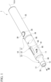
- FIG. 1 is a perspective view of a suction device.
- the suction device 1 shown in FIG. 1 is a so-called non-combustion suction device, in which a user tastes the flavor of tobacco by inhaling aerosol atomized by heating through a tobacco (tobacco capsule).
- the suction device 1 includes a main body unit 10, and a cartridge 11 and a tobacco capsule 12 that are detachably attached to the main body unit 10.
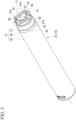
- FIG. 2 is an exploded perspective view of the suction device 1.
- the main body unit 10 includes a power supply unit 21, a holding unit 22, and a mouthpiece 23.
- the power supply unit 21, the holding unit 22, and the mouthpiece 23 are each formed in a tubular shape with the axis O as a central axis, and are arranged in line with the axis O.
- the power supply unit 21 and the holding unit 22 are detachably connected, and the holding unit 22 and the mouthpiece 23 are detachably connected.
- the direction along the axis O is referred to as the axial direction.
- a direction from the mouthpiece 23 toward the power supply unit 21 in the axial direction is called the non-suction side
- a direction from the power supply unit 21 toward the mouthpiece 23 is called the suction side.
- a direction intersecting the axis O in a plan view seen from the axial direction may be referred to as a radial direction
- a direction around the axis O may be referred to as a circumferential direction.
- "direction" means two directions, and when indicating one of the "directions", it is referred to as "side".
- FIG. 3 is a perspective view of the power supply unit 21.
- the power supply unit 21 includes a cylindrical housing 31, a storage battery unit (not shown) housed in the housing 31, and a pin electrode 33.
- the housing 31 has an exterior cylindrical portion 35, an interposition member 36, and a connecting mechanism 37.
- the exterior tubular portion 35 is formed in a cylindrical shape with the axis O as the central axis.
- the interposition member 36 is formed in a cylindrical shape with the axis O as the central axis.
- the interposition member 36 is fitted into the exterior tubular portion 35 from the holding unit 22 side in the axial direction.
- a button exposure hole 38 is formed in the vicinity of the end portion of the outer tubular portion 35 on the holding unit 22 side in the axial direction.
- the button exposure hole 38 penetrates the exterior tubular portion 35 in the radial direction.
- a button 39 is housed in the button exposure hole 38.
- the button 39 is configured to be movable in the radial direction.
- the button 39 presses a switch element (not shown) of the storage battery unit as it moves inward in the radial direction.
- a temperature of the resistor pattern 142 of the heating part 104 rises.
- the aerosol source is atomized to generate aerosol.
- the configuration of the heating part 104 will be described later.
- the surface of the button 39 is exposed on the outer peripheral surface of the exterior tubular portion 35 through the button exposure hole 38.
- the button 39 is not limited to the one that moves in the radial direction, but may be one that slides in the axial direction, for example. Further, the suction device 1 may be operated by a touch sensor or the like instead of the button 39.
- FIG. 4 is a plan view of the power supply unit 21 viewed from the holding unit 22 side in the axial direction.
- the connecting mechanism 37 includes a connection cap 40, a first connecting member 41, and an annular piece 42.
- connection cap 40 is formed of an elastic resin material such as silicone resin.
- the connection cap 40 includes a base portion 45, a flange portion (not shown) protruding outward in the radial direction at an end portion of the base portion 45 on the side opposite to the holding unit 22 in the axial direction, and a surrounding convex portion 46.
- the base portion 45 is formed in a cylindrical shape with the axis O as the central axis.
- An electrode insertion hole 47 through which the pin electrode 33 is inserted is formed in the base portion 45.
- the electrode insertion hole 47 penetrates the base portion 45 in the axial direction and communicates with the inside of the housing 31.
- the pin electrode 33 protrudes from the base portion 45 toward the holding unit 22 side in the axial direction through the electrode insertion hole 47.
- the surrounding convex portion 46 protrudes in the axial direction from the end surface of the base portion 45 that faces the holding unit 22 side in the axial direction.
- the surrounding convex portion 46 is formed in a substantially annular shape extending along the outer peripheral edge of the base portion 45.
- the surrounding convex portion 46 surrounds the pin electrode 33 at a position separated from the pin electrode 33 to the outside in the radial direction.
- the surrounding convex portion 46 has a notch portion 46a formed in a part of the ring shape of the surrounding convex portion 46.
- Three notch portions 46a are formed evenly at intervals of 120 degree in the circumferential direction.
- the notch portion 46a functions as a circulation path of air.
- the surrounding convex portion 46 may be located radially inside the outer peripheral edge of the base portion 45 as long as the surrounding convex portion 46 surrounds the pin electrode 33.
- the surrounding convex portion 46 is not limited to the annular shape, and may have a polygonal shape or the like.
- the number and position of the notch portions 46a may be changed as appropriate.
- meaning of the "surrounding" in the surrounding convex portion is not limited to the one that extends intermittently, but also includes the one that extends continuously.
- the surrounding convex portion 46 is formed in a continuous annular shape, it is necessary to separately form an air flow path.
- the surrounding convex portion 46 in the present embodiment can be appropriately modified as long as it surrounds the pin electrode 33.
- the surrounding convex portion 46 is formed in a triangular shape that is sharpened toward the holding unit 22 side in the axial direction in a longitudinal sectional view along the axial direction.
- the protruding height of the surrounding convex portion 46 from the base portion 45 is lower than that of the pin electrode 33.
- the protruding height of the surrounding convex portion 46 may be higher than that of the pin electrode 33.
- the vertical cross-sectional shape of the surrounding convex portion 46 is not limited to the triangular shape.
- the first connecting member 41 includes a base cylindrical portion (not shown) arranged in the housing 31, a vertical engaging convex portion (first vertical engaging convex portion 51a to third vertical engaging convex portion 51c), and a lateral engaging convex portion 52.
- An end portion of the base tubular portion on the holding unit 22 side in the axial direction surrounds the periphery of the connection cap 40.
- An outer flange portion 55 protruding outward in the radial direction is formed at an end portion of the base tubular portion on the side of the holding unit 22 in the axial direction.
- the vertical engaging convex portions 51a to 51c protrude from the outer flange portion 55 toward the holding unit 22 side (suction side) in the axial direction.
- a plurality of the vertical engaging convex portions 51a to 51c are formed at intervals in the circumferential direction.
- each of the vertical engaging convex portions 51a to 51c is evenly arranged in the circumferential direction at intervals of 120 degree.
- the vertical engaging convex portion may be single or plural. Further, the pitch of the vertical engaging convex portions 51a to 51c can be changed appropriately. In this case, the plurality of vertical engaging protrusions 51a to 51c may be arranged unevenly.
- the vertical engaging convex portions 51a to 51c are arranged so that the above-described pin electrodes 33 are not arranged on the virtual straight lines La to Lc connecting the axis O and the center of each of the vertical engaging convex portions 51a to 51c in the circumferential direction.
- the pin electrodes 33 are arranged at a position that is line-symmetric with respect to the virtual straight line La that connects the first vertical engaging convex portion 51a and the axis O. That is, the virtual straight line T1 connecting the pin electrodes 33 and the virtual straight line La are orthogonal to each other, and the distances from the virtual straight line La to the pin electrodes 33 are equal to each other.
- tip ends of the longitudinal engaging convex portions 51a to 51c located on the holding unit 22 side in the axial direction are located on the holding unit 22 side in the axial direction with respect to the tip ends of the pin electrodes 33.
- the vertical engaging convex portions 51a to 51c are formed in a rectangular shape as viewed from the side in the radial direction.
- the surface facing inward in the radial direction is an inclined surface whose thickness in the radial direction gradually decreases toward the holding unit 22 side in the axial direction. This inclined surface functions as a guide for smoothly guiding the vertical engaging convex portions 51a to 51c to the engaging recess 180 of the cartridge 11 described later.
- the lateral engaging convex portion 52 protrudes outward in the radial direction from the outer flange portion 55.
- the lateral engaging convex portion 52 is formed in a rectangular shape in a plan view as seen in the axial direction.
- a plurality of lateral engaging convex portions 52 are formed at intervals in the circumferential direction.
- the four lateral engaging convex portions 52 are evenly arranged at 90 degree intervals in the circumferential direction.
- the one lateral engaging convex portion 52 is arranged at the same position in the circumferential direction as the first vertical engaging convex portion 51a.
- the lateral engaging convex portion 52 may be singular or plural. Further, the pitch of the lateral engaging convex portions 52 may be changed appropriately. In this case, the plurality of lateral engaging convex portions 52 may be arranged unevenly.
- the annular piece 42 is formed in a thin annular shape.
- the above-described base cylinder portion is inserted into the annular piece 42 from the holding unit 22 side in the axial direction.
- a flexure portion 56 is formed in a part of the annular piece 42 in the circumferential direction.
- the flexure portion 56 is formed in an arch shape that bulges outward in the radial direction.
- the flexure portion 56 is configured to be elastically deformable in the radial direction.
- the flexure portion 56 is positioned radially inward of the radially outer end surface of the lateral engaging convex portion 52.
- a plurality of the flexure portions 56 described above are formed at intervals in the circumferential direction.
- the flexure portion 56 is arranged at the same position in the circumferential direction as the pair of lateral engaging convex portions 52 that are opposed to each other in the radial direction (left-right direction) among the lateral engaging convex portions 52.
- the number of the flexure portions 56 may be changed appropriately.
- the flexure portion 56 may be formed corresponding to each lateral engaging convex portion 52, or may be formed corresponding to only one lateral engaging convex portion 52.
- FIG. 5 is an exploded perspective view of the holding unit 22.
- the holding unit 22 is detachably attached to the power supply unit 21 and the mouthpiece 23.
- the holding unit 22 includes a container holding cylinder 60, a transparent cylinder 61, a second connecting member 62, and a sleeve 63.
- the container holding cylinder 60 is formed in a cylindrical shape with the axis O as the central axis.
- An observation hole 65 is formed in the central portion of the container holding cylinder 60 in the axial direction.
- the observation hole 65 penetrates the container holding cylinder 60 in the radial direction.
- the observation hole 65 is formed in an oval shape having the axial direction as the longitudinal direction.
- the observation holes 65 are formed in a pair in the portions of the container holding cylinder 60 that face each other in the radial direction. The number, position, shape, and the like of the observation holes 65 can be changed as appropriate.
- a ventilation port 66 is formed in a portion of the container holding cylinder 60, and is located closer to the power supply unit 21 side (anti-suction port side) than the observation hole 65.
- the ventilation port 66 penetrates the container holding cylinder 60 in the radial direction.
- the ventilation port 66 communicates the inside and outside of the holding unit 22.
- the ventilation ports 66 are formed in a pair in portions of the container holding cylinder 60 so as to face each other in the radial direction (the front and back directions). The number, position, shape, and the like of the ventilation ports 66 can be changed as appropriate.
- the transparent cylinder 61 is formed of a material having light transparency.
- the transparent cylinder 61 is inserted into the container holding cylinder 60.
- the transparent cylinder 61 is arranged on the mouthpiece 23 side (suction side) in the axial direction with respect to the ventilation port 66, and covers the observation hole 65 from the inside in the radial direction. That is, the user can visually recognize an inside of the holding unit 22 through the observation hole 65 and the transparent cylinder 61.
- the holding unit 22 may have a configuration that does not have the observation hole 65 and the transparent cylinder 61.
- the second connecting member 62 is locked to the above-described first connecting member 41 when the holding unit 22 is connected to the power supply unit 21.
- the second connecting member 62 includes a fitting cylinder 70, a guide cylinder 71, and a locking piece 72.
- the fitting cylinder 70 is formed in a cylindrical shape with the axis O as the central axis.
- the fitting cylinder 70 is fitted into a portion, where is located closer to the power supply unit 21 in the axial direction than the transparent cylinder 61, of the container holding cylinder 60.
- the guide cylinder 71 is arranged coaxially with the fitting cylinder 70.
- the guide cylinder 71 extends from the fitting cylinder 70 toward the mouthpiece 23 side in the axial direction.
- the guide cylinder 71 is formed in a tapered cylinder shape whose inner diameter gradually increases toward the mouthpiece 23 side in the axial direction.
- the outer diameter of the guide cylinder 71 is smaller than the outer diameter of the fitting cylinder 70.
- An escape portion 74 is formed in the guide cylinder 71 at a position where it overlaps with the above-described ventilation port 66 when viewed from the side in the radial direction.
- the escape portion 74 is formed, for example, in a U-shape that opens toward the mouthpiece 23 side in the axial direction.
- the ventilation port 66 opens into the holding unit 22 through the escape portion 74.
- the escape portion 74 may have any shape as long as at least a part of the ventilation port 66 is exposed in the holding unit 22. In a case in which the guide cylinder 71 and the ventilation port 66 are arranged at different positions in the axial direction, the guide cylinder 71 may not have the escape portion 74.
- FIG. 6 is a perspective view showing a connection structure of the first connecting member 41 and the second connecting member 62.
- the locking piece 72 protrudes from the fitting cylinder 70 toward the power supply unit 21 in the axial direction.
- the locking piece 72 is formed in an L shape in a side view as seen from the radial direction.
- the locking piece 72 has a vertically extending portion 80 and a horizontally extending portion 81.
- the vertically extending portion 80 protrudes from the fitting cylinder 70 toward the power supply unit 21 side in the axial direction.
- the horizontally extending portion 81 extends in a cantilever manner from an end part of the vertically extending portion 80 on the power supply unit 21 side in the axial direction toward one side in the circumferential direction.
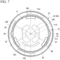
- FIG. 7 is a plan view of the holding unit 22 and the cartridge 11 as viewed from the power supply unit 21 side in the axial direction.
- an engaging recess 85 that is recessed outward in the radial direction is formed at one end portion in the circumferential direction in the horizontally extending portion 81.
- the engaging recess 85 is formed in a semicircular shape outward in the radial direction.
- a plurality of the locking pieces 72 described above are formed at intervals in the circumferential direction.
- the locking pieces 72 are evenly arranged at 90 degree intervals in the circumferential direction.
- An engaging groove 83 into which the above-described lateral engaging convex portion 52 is inserted is defined between the locking pieces 72 adjacent to each other in the circumferential direction.
- the engaging groove 83 is formed in an L shape in a side view.
- the power supply unit 21 and the holding unit 22 are detachable by connecting the locking piece 72 and the lateral engaging convex portion 52. That is, in order to connect the power supply unit 21 and the holding unit 22, after inserting the lateral engaging convex portion 52 in the engaging groove 83 in the axial direction, the power supply unit 21 and the holding unit 22 are relatively rotated around the axis O. Then, the lateral engaging convex portion 52 axially engages between the horizontally extending portion 81 and the fitting cylinder 70. In the process in which the power supply unit 21 and the holding unit 22 relatively rotate about the axis O, the flexure portion 56 of the annular piece 42 fits into the engaging recess 85.
- the flexure portion 56 engages with the engaging recess 85 in the circumferential direction.
- the power supply unit 21 and the holding unit 22 are assembled to each other in a state in which they are positioned in the axial direction and the circumferential direction.
- the engaging groove 83 of the present embodiment is formed in a taper shape between the fitting cylinder 70 and the horizontally extending portion 81 such that the width in the axial direction becomes gradually narrower from the other side to the one side in the circumferential direction.
- an end surface of the horizontally extending portion 81 facing the mouthpiece 23 side in the axial direction is an inclined surface gradually extending toward the power supply unit 21 side in the axial direction from the other side toward the one side in the circumferential direction.
- the lateral engaging convex portion 52 is formed in a taper shape in which the width in the axial direction gradually decreases from one side toward the other side in the circumferential direction. Specifically, an end surface of the above-described lateral engaging convex portion 52 facing the side opposite to the axial holding unit 22 is inclined so as to gradually extend toward the mouthpiece 23 side in the axial direction from one side to the other side in the circumferential direction.
- the sleeve 63 is press-fitted into a portion, where is located closer to the mouthpiece 23 side in the axial direction than the transparent cylinder 61, of the container holding cylinder 60 by press fitting or the like.
- the transparent cylinder 61 described above is axially held between the second connecting member 62 and the sleeve 63.
- a female screw portion 63a is formed on the inner peripheral surface of the sleeve 63.
- FIG. 8 is an exploded perspective view of the mouthpiece 23 corresponding to the line VIII-VIII in FIG. 1 .
- the mouthpiece 23 includes a mouthpiece body 90 and an anti-slip member (a first anti-slip member 91 and a second anti-slip member 92).
- the mouthpiece 23 is formed with a suction port 23a capable of accommodating the tobacco capsule 12.
- the mouthpiece body 90 is formed in a multi-stage tubular shape with the axis O as the central axis.
- a male screw portion 90a is formed at an end portion of the mouthpiece body 90 on the side of the holding unit 22 in the axial direction.
- the male screw portion 90a of the mouthpiece body 90 is screwed to be detachably attached to the female screw portion 63a of the sleeve 63 described above.
- the mouthpiece body 90 may be configured to be attached to and detached from the sleeve 63 by a method other than screwing, for example, fitting or the like.
- An abutting flange 93 is formed on a portion, where is axially opposite to the holding unit 22 with respect to the male screw portion 90a, of the mouthpiece body 90.
- the abutting flange 93 is formed in an annular shape protruding outward in the radial direction.
- the abutting flange 93 abuts the holding unit 22 in the axial direction when the mouthpiece 23 is attached to the holding unit 22.
- An outer diameter of the abutting flange 93 is gradually reduced as it is separated from the holding unit 22 in the axial direction.
- a partition portion 94 that partitions an inside of the mouthpiece body 90 in the axial direction is formed at the end of the mouthpiece body 90 on the side of the holding unit 22 in the axial direction.
- a through hole 95 penetrating the partition portion 94 in the axial direction is formed in the partition portion 94 at a position overlapping the axis O.
- the through hole 95 has, for example, an oval shape with one longitudinal direction in the radial direction.
- the plan view shape of the through hole 95 may be a perfect circle, a polygon, or the like.
- the first anti-slip member 91 is integrally formed of a resin material such as silicone resin.
- the first anti-slip member 91 includes a ring portion 96, a fitting protrusion 97, and a contact protrusion 98.
- the ring portion 96 is fitted in the mouthpiece body 90 from the holding unit 22 side in the axial direction.
- the first anti-slip member 91 is axially positioned with respect to the mouthpiece body 90 by the ring portion 96 abutting the partition portion 94 in the axial direction.
- a communication hole 96a is formed in the center of the ring portion 96. The communication hole 96a connects the inside of the holding unit 22 and the inside of the mouthpiece body 90 through the through hole 95 described above.
- the fitting protrusions 97 are formed in a pair on the inner peripheral edge of the ring portion 96 at positions radially opposite to each other with the communication hole 96a interposed therebetween.
- the fitting protrusions 97 protrude from the ring portion 96 in the axial direction to the side opposite to the holding unit 22.
- the fitting protrusions 97 are fitted to both end portions of the through hole 95 in the radial direction.
- the first anti-slip member 91 is positioned in the circumferential direction with respect to the mouthpiece body 90.
- the configuration in which the fitting protrusion 97 is fitted in the through hole 95 is described, but the fitting protrusion 97 may be fitted into a hole different from the through hole 95.
- the contact protrusion 98 protrudes from the ring portion 96 toward the holding unit 22 side in the axial direction.
- the contact protrusion 98 is formed in a circular shape centered on the axis O. In the present embodiment, the contact projections 98 are formed in two concentric circles.
- the first anti-slip member 91 may not have the contact protrusion 98.
- the second anti-slip member 92 is an integrally formed of a resin material such as silicone resin.
- the second anti-slip member 92 is fitted in the mouthpiece body 90 from the side opposite to the axial holding unit 22.
- the second anti-slip member 92 is axially positioned with respect to the mouthpiece body 90 by being abutted against the partition portion 94 in the axial direction.
- the tobacco capsule 12 is detachably mounted in the mouthpiece body 90 from the side opposite to the holding unit 22 in the axial direction.
- the tobacco capsule 12 includes a capsule portion 77 and a filter portion 78.
- the tobacco capsule 12 is configured as a flavor source container.
- the capsule portion 77 is formed in a bottomed cylindrical shape with the axis O as the central axis such that a bottom wall portion (not shown) closing an inner opening space of the capsule portion 77 on the holding unit 22 side in the axial direction.
- a mesh opening that penetrates the bottom wall portion in the axial direction is formed in the bottom wall portion of the capsule portion 77.
- the filter portion 78 is fitted in the capsule portion 77 from the side opposite to the holding unit 22 in the axial direction.
- tobacco leaves are enclosed in the space defined by the capsule portion 77 and the filter portion 78.
- a flavor source other than tobacco leaf may be enclosed.
- the cartridge 11 stores a liquid aerosol source and atomizes the liquid aerosol source.
- the cartridge 11 is housed in the transparent cylinder 61 of the holding unit 22.
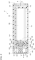
- FIG. 9 is a sectional view taken along the axial direction (axis line Q) of the cartridge 11.
- FIG. 10 is an exploded perspective view of the cartridge 11.
- the cartridge 11 includes a bottomed cylindrical tank 101, a substantially columnar shape gasket 102 housed in the tank 101, a substantially plate-shaped mesh body 103, a heating part 104, an atomization container 105, a heating part holder 106 that closes an opening 110 of the tank 101, and an end cap 107 that is attached to the tank 101 on an opposite side to the heating part holder 106 in the axial direction.
- FIG. 11 is a perspective view of the tank 101 viewed from the opening 110 side.
- ribs 112 are formed on the inner peripheral wall 111 of the tank 101.
- Four ribs 112 are formed at substantially equal intervals in the circumferential direction.
- the ribs 112 are formed along the axis line Q direction of the inner peripheral wall 111 of the tank 101.
- the rib 112 is provided between a bottom plate 113 provided near the end of the tank 101 on the mouthpiece 23 side and a part slightly before the end (tip end) on the opening 110 side.
- the ribs 112 are formed in a rectangular shape when viewed from the axis line Q direction. The shape and the number of ribs 112 may be changed as appropriate.
- the tank 101 is made of a light-transmissive material, and the remaining amount of the aerosol source contained therein can be visually confirmed.
- An aerosol passage pipe 114 is formed on the inner peripheral wall 111 of the tank 101 along the axis line Q direction.
- the aerosol channel pipe 114 is formed from an end portion of the opening 110 to the bottom plate 113.
- a through hole 115 penetrating the bottom plate 113 is formed in the bottom plate 113 of the tank 101.
- the inside of the aerosol flow path pipe 114 and the through hole 115 are in communication with each other.
- the aerosol flow path pipe 114 and the through hole 115 become a flow path (arrow in FIG. 9 ) of atomized aerosol.
- the axis line Q coincides with the axis O of the main body unit 10 when the cartridge 11 is housed in the transparent cylinder 61.
- the axis line Q is an axis line that is common to each part that constitutes the cartridge 11.
- the axis line Q is not limited to the axis line Q of the tank 101, but is used in the description of each part constituting the cartridge 11.
- FIG. 12 is a perspective view of the gasket 102.
- the gasket 102 is formed in a substantially columnar shape having an outer diameter substantially equal to the inner diameter of the tank 101.
- the gasket 102 is housed in the tank 101.
- a concave groove 121 into which the aerosol channel pipe 114 is capable of being inserted is formed on the peripheral edge of the main body 120 of the gasket 102.
- the concave groove 121 is formed over the entire length in the axis line Q direction, and is formed in a substantially arc shape along the outer shape of the aerosol flow channel tube 114.
- a flange portion 122 is formed on the outer peripheral edge of one surface 120a of the body portion 120 on the mouthpiece 23 side such that the flange portion 122 rises from the one surface 120a to the mouthpiece 23 side.
- the concave groove 121 may be aligned with the position of the aerosol flow path pipe 114 and inserted in the axis line Q direction.
- the gasket 102 is inserted to a position where the flange portion 122 of the gasket 102 abuts on the rib 112 of the tank 101.
- the gasket 102 is held at the position where it abuts against the rib 112.
- the outer peripheral surface of the gasket 102 is in contact with the inner peripheral wall 111 of the tank 101.
- the recessed groove 121 of the gasket 102 is in contact with the outer peripheral surface of the aerosol flow channel tube 114.
- the mesh body 103 is held on the other surface 120b of the main body 120 on the power supply unit 21 side.
- a concave portion 123 capable of accommodating the mesh body 103 is formed substantially in the center of the other surface 120b.
- the mesh body 103 is positioned and the posture of the mesh body 103 is maintained. That is, the mesh body 103 is configured to be fitted in the recess 123.
- a through hole 124, through which an aerosol source can flow, is formed in the bottom surface 123a of the recess 123 and in the radial center of the gasket 102. Two through holes 124 are formed in parallel in a rectangular shape when viewed from the axis line Q direction.
- the mesh body 103 is a porous member having a liquid absorbing property.
- the mesh body 103 is formed of, for example, a cotton fiber material.
- the mesh body 103 is formed in substantially the same shape as the recess 123 of the gasket 102.
- the inside of the tank 101 is partitioned into a liquid storage chamber 130 defined on the mouthpiece 23 side of the mesh body 103 and an opening chamber 131 on the power supply unit 21 side of the mesh body 103.
- a liquid aerosol source is stored in the liquid storage chamber 130.
- the opening chamber 131 is a chamber for atomizing the aerosol source sucked up by the mesh body 103.
- a first surface 103a of the mesh body 103 on the mouthpiece 23 side is in contact with the bottom surface 123a of the gasket 102.
- a second surface 103b of the mesh body 103 on the power supply unit 21 side is exposed to the opening chamber 131.
- the heating part 104 is provided so as to be connected to the second surface 103b of the mesh body 103 exposed in the opening chamber 131.
- FIG. 13 is a plan view of the heating part 104 viewed from the power supply unit 21 side.
- the heating part 104 is for atomizing a liquid aerosol source.
- the heating part 104 is housed in the opening chamber 131.
- the heating part 104 includes a substantially rectangular parallelepiped porous ceramic substrate 140.
- the porous ceramic substrate 140 is configured as a main body of the heating part 104. The shape and thickness of the porous ceramic substrate 140 may be changed appropriately.
- One surface 140a of the porous ceramic substrate 140 on the mouthpiece 23 side is in contact with the second surface 103b of the mesh body 103. As a result, the aerosol source absorbed by the mesh body 103 is sucked up into the porous ceramic substrate 140.
- a pair of electrode patterns 141 is provided on the heat generating surface 140b, which is the other surface of the porous ceramic substrate 140 on the power supply unit 21 side.
- the pair of electrode patterns 141 have a strip shape along substantially both sides in the radial direction of the heat generating surface 140b having a long shape.
- the heat generating surface 140b is provided with a resistor pattern 142 that connects the pair of electrode patterns 141.
- the resistor pattern 142 has a meandering curved shape when viewed from the direction of the axis line Q. Both end portions of the resistor pattern 142 are connected to the pair of electrode patterns 141, respectively, and are configured to be electrically conductive.
- the resistor pattern 142 In the resistor pattern 142, one ends of a pair of U-shaped arcs are connected to each other, and the other ends are connected to the pair of electrode patterns 141, respectively.
- the resistor pattern 142 is configured to be able to raise its temperature to a predetermined temperature when electricity flows through the electrode pattern 141. A temperature of the resistor pattern 142 rises to an appropriate temperature at which aerosol is generated.
- the shape of the resistor pattern 142 is arbitrary and may not be a meandering curved shape.
- the pair of electrode patterns 141 and the resistor pattern 142 are arranged on the glass layer 143 formed on the heat generating surface 140b.
- a liquid supply channel 145 is formed on the porous ceramic substrate 140.
- the liquid supply channel 145 is a flow path through which a liquid (aerosol source) flows.
- the liquid is configured to be capable of proceeding in the liquid supply channel 145 by, for example, a capillary phenomenon.
- the liquid supply channel 145 causes the aerosol source to flow from one surface 140a toward the heat generating surface 140b.
- the manufacturing method of the heating part 104 will be described in detail below.
- FIG. 14 is a perspective view of the atomization container 105.
- the atomization container 105 is formed in a multistage cylindrical shape with the axis line Q as the central axis.
- the main body part 150 of the atomizing container 105 has a first cylinder portion 151 on the mouthpiece 23 side, the outer diameter of which is substantially the same as the inner diameter of the tank 101, and a second cylinder portion 152 on the power supply unit 21 side, the outer diameter of which is substantially the same as the outer diameter of the tank 101.
- the atomization container 105 is arranged so as to close the opening 110 of the tank 101.
- the first tubular portion 151 is housed in the tank 101.
- a concave groove 153 into which the aerosol flow path tube 114 can be inserted is formed on the peripheral edge of the first tubular portion 151.
- the recessed groove 153 is formed over the entire length of the first tubular portion 151 in the axis line Q direction, and is formed in a substantially arc shape along the outer shape of the aerosol flow channel pipe 114.
- a through hole 154, through which the heating part 104 can be inserted, is formed in the center of the first tubular portion 151 in the radial direction.
- the through hole 154 is formed to have substantially the same shape as the outer shape of the heating part 104.
- the heating surface 140b of the heating part 104 is configured to be exposed to the power supply unit 21 side (opening chamber 131).
- the second tubular portion 152 is continuously provided on the power supply unit 21 side of the tank 101.
- the step surface 152a between the first cylinder portion 151 and the second cylinder portion 152 abuts on the end surface of the tank 101 on the power supply unit 21 side, whereby the tank 101 and the atomization container 105 are positioned.
- a through hole 157 is formed in the center of the second tubular portion 152 in the radial direction so as to penetrate in the axis line Q direction.
- the through hole 157 communicates with the through hole 154 of the first tubular portion 151.
- the through hole 157 communicates with the groove 153.
- the through hole 157 communicates with the aerosol flow path pipe 114.
- the through hole 157 of the second tubular portion 152 is formed in a size that allows the power supply bypass portion 161 provided in the heating part holder 106 to be inserted therethrough.
- the space S defined by the through hole 154 of the first tubular portion 151 and the through hole 157 of the second tubular portion 152 is configured as an aerosol generating portion.
- the aerosol generated in the space S passes through the aerosol flow path tube 114 and is guided to the mouthpiece 23 side (arrow in FIG. 9 ).
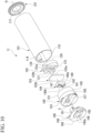
- FIG. 15 is a perspective view of the heating part holder 106.
- the heating part holder 106 includes a disc-shaped main body portion 160 having the axis line Q as the central axis, and a power supply bypass portion 161 provided in the main body portion 160.
- the main body portion 160 is formed in a disc shape, and is configured to be capable of contacting the end surface of the second tubular portion 152 of the atomization container 105 on the power supply unit 21 side.
- the main body portion 160 is formed with a through hole 162 penetrating in the axis line Q direction.
- the through hole 162 communicates with the through hole 157 of the atomization container 105. Air is taken into the cartridge 11 through the through hole 162. More specifically, when the user inhales from the mouthpiece 23, the inside of the suction device 1 has a negative pressure. Then, air is taken into the suction device 1 from the ventilation port 66 of the holding unit 22.
- the air taken in from the ventilation port 66 is guided from the outside of the surrounding convex portion 46 to the inside of the surrounding convex portion 46 through the notch portion 46a. After that, the air flows into the cartridge 11 through the through hole 162 of the main body 160, and flows in the aerosol flow pipe 114 together with the aerosol generated near the heating part 104.
- the power supply bypass portion 161 has a pair of electrode plates 165 and 165.
- the electrode plate 165 is formed by bending a metal plate material.
- the electrode plate 165 includes a pin electrode connecting portion 166 exposed on a surface 160a of the main body portion 160 on the power supply unit 21 side, an extending portion 167 provided continuously with the pin electrode connecting portion 166 and extending in the axis line Q direction, and a heating part connecting portion 168 folded back at the end of the portion 167 on the mouthpiece 23 side and extending in the radial direction.
- a spacer 169 is arranged between the pair of electrode plates 165.
- the pin electrode connecting portion 166 contacts the pin electrode 33 of the power supply unit 21 and is electrically connected. Further, when the heating part holder 106 is attached to the tank 101, the heating part connecting portion 168 contacts the electrode pattern 141 of the heating part 104 and is electrically connected.
- three engaging recesses 180 facing the power supply unit 21 are formed on peripheral walls of the atomization container 105 and the heating part holder 106.
- the three engaging recesses 180 are arranged at equal intervals in the circumferential direction (120degree intervals in the circumferential direction).
- the engaging recesses 180 are formed so that the outside in the radial direction and the end on the power supply unit 21 side are opened.
- a tapered flat chamfer is formed in which the circumferential width of the engaging recess 180 gradually increases toward the end portion.
- the vertical engaging convex portions 51a to 51c of the first connecting member 41 are inserted into the three engaging recesses 180 formed in this way. Thereby, the cartridge 11 and the first connecting member 41 are connected, and the cartridge 11 and the first connecting member 41 are positioned in the circumferential direction.
- the end cap 107 is a substantially annular plate-shaped member attached to the end portion of the tank 101 on the suction port side.
- a through hole 171 is formed at the center of the end cap 107 in the radial direction.
- the flow of air in the cartridge 11 (flow of aerosol) will be described with reference to FIG. 9 .
- the air is guided into the opening chamber 131 (space S).
- the aerosol source (liquid) guided near the heat generating surface 140b of the heating part 104 changes into an aerosol (gas) as the resistor pattern 142 heats up.
- the aerosol generated in the vicinity of the heat generating surface 140b is introduced into the aerosol flow path pipe 114 of the tank 101 from the through hole 157 of the atomizing container 105 together with the air taken in the opening chamber 131 (space S).
- the aerosol passes from the aerosol flow path tube 114 through the through hole 115 of the bottom plate 113, and flows from the through hole 171 of the end cap 107 to the mouthpiece 23.
- the user can suck the aerosol together with the air from the suction port 23a of the mouthpiece 23.
- the configuration of the heating part 104 will be described in detail. Note that, in the following embodiments, the drawings are appropriately simplified or modified, and the dimensional ratios and shapes of the respective parts are not necessarily drawn accurately.
- FIG. 13 is a plan view showing the heating part (porous ceramic heating element) 104.
- the heating part 104 includes a porous ceramic substrate 140 formed in a rectangular parallelepiped shape having, for example, a long side of 6.0 mm, a short side of 3.0 mm, and a thickness of 3.0 mm, a glass layer 143 fixed by sintering to a heat generating surface 140b that is one surface of the porous ceramic substrate 140 and functions as a heating surface, and a resistor pattern 142 and an electrode pattern 141, which are respectively fixed on the glass layer 143 by sintering.
- the heat generating surface 140b of the porous ceramic substrate 140 has a rectangular shape and functions as an atomizing surface of a predetermined liquid that has infiltrated into the heating part 104 by a capillary phenomenon.
- the porous ceramic substrate 140 is a porous inorganic sintered body containing alumina, zirconia, mullite, silica, titania, silicon nitride, silicon carbide, or carbon, as a main component, and has, for example, continuous ventilation holes having an average pore size of 0.15 ⁇ m to 500 ⁇ m, preferably 1.5 ⁇ m to 72 ⁇ m.
- the porous inorganic sintered body has a ratio of porosity to tortuosity (ratio of porosity to tortuosity coefficient) of, for example, 21 or more, preferably 26 or more, and an average porosity of, for example, 30% by volume to 90% by volume, preferably 40% by volume to 71% by volume.
- the glass layer 143 is made of a glass containing Ba, B, Zn, Si, for example, borosilicate glass, and the glass layer 143 has a softening point lower than the firing temperature of the porous ceramic substrate 140 and equal to or higher than the firing temperatures of the resistor pattern 142 and the electrode pattern 141.
- the glass layer 143 is a dense glass film fixed to the heating surface 140b of the porous ceramic substrate 140 by sintering with a thickness of, for example, 100 ⁇ m or less, preferably 3.0 ⁇ m to 90 ⁇ m.
- the glass layer 143 is formed in the same pattern as the later-described resistor pattern 142 and the electrode pattern 141 or a slightly larger pattern, and has substantially the same area as the resistor pattern 142 and the electrode pattern 141.
- the resistor pattern 142 is a heating element, in which metal powder of silver, palladium, ruthenium oxide, or the like is bound by a thick film glass having a melting point below a thick film firing temperature described later, to have a thickness of 8 ⁇ m to 21 ⁇ m and a value of 1 Q to 3 ⁇ , preferably 1.1 Q to 2.7 Q. It is a thick film resistor that is fixed on the glass layer 143 by sintering in an S-shaped pattern on the heating surface 140b of the porous ceramic substrate 140.
- the resistor pattern 142 has a pair of U-shaped portions, one end of which is connected to each other to form an S-shape.
- the resistor pattern 142 is formed on the heat generating surface 140b of the porous ceramic substrate 140 so as to have a size of 5% to 30%, preferably 13% to 21%, with respect to the entire heat generating surface 140b.
- the pair of electrode patterns 141 have the same conductivity as that of a conductor by bonding metal powders such as aluminum, nickel, copper, silver, platinum, and gold with a thick film glass having a melting point equal to or lower than a thick film firing temperature described later. It is a thick film conductor that has a rectangular shape and is fixed on the glass layer 143 by sintering at both end portions of the heat generating surface 140b of the porous ceramic substrate 140.
- the pair of electrode patterns 141 are connected to the resistor pattern 142 by overlapping the tip ends of the pair of U-shaped portions extending in an arc shape from the other ends to the electrode pattern 141 side.
- the pair of electrode patterns 141 are formed on the heat generating surface 140b of the porous ceramic substrate 140 so as to have a size of 5% to 20% with respect to the entire heat generating surface 140b.
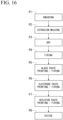
- FIG. 16 shows the manufacturing process of the heating part 104.
- the material of the porous ceramic substrate 140 such as alumina powder, inorganic binder, foaming agent, organic binder, water, wax, or the like are compounded and mixed at a predetermined mixing ratio so as to have a predetermined porosity of, for example, 30% to 90%.
- the mixture is kneaded using a kneader to obtain clay-like embryo soil.
- the foaming agent is, for example, resin beads.
- the embryo soil is molded into a plate-shaped green sheet having a predetermined thickness of about 4 mm by using a vacuum extrusion molding machine. Further, a groove for division is formed on the green sheet by pressing a linear blade.
- the green sheet obtained in the extrusion molding step P2 is dried in the drying step P3 and then fired in the firing step P4 at a firing temperature of, for example, 1300°C to 1500°C.
- a firing temperature of, for example, 1300°C to 1500°C.
- a thick film glass paste containing, for example, borosilicate glass powder, a resin binder, an organic solvent, or the like is screen-printed at a plurality of locations on the ceramic plate obtained in the firing step P4 in the pattern of the glass layer 143 shown in FIG. 13 .
- it is fired at a temperature lower than the firing temperature of the ceramic plate, for example, 800°C to 1000°C.
- the resin binder, the organic solvent, or the like in the thick film glass paste disappear, and at the same time, the borosilicate glass melts and the glass layer 143 is fixed on the ceramic plate by sintering.
- a thick film electrode paste containing silver (Ag) powder, a small amount of borosilicate glass, a resin binder, an organic solvent, or the like is screen-printed on the glass layer 143 at a plurality of positions on the ceramic plate obtained in the firing step P4 in the pattern of the electrode pattern 141 shown in FIG. 13 .
- the glass layer 143 is fired at a firing temperature equal to or lower than the firing temperature, for example, a thick film firing temperature of 700°C to 900°C.
- the resin binder, the organic solvent, or the like in the electrode paste, that is, the conductor paste disappears, and at the same time, the borosilicate glass is melted and the silver powder is bonded by the molten borosilicate glass, so that the electrode pattern 141 is fixed on the glass layer 143 on the ceramic plate by sintering.
- a thick film resistance paste which includes silver-palladium (Ag - Pd) powder, borosilicate glass, a resin binder, an organic solvent, or the like and has a sheet resistance of 100 to 200 mQ/sq for example, is screen-printed in the pattern of the resistor pattern 142 shown in FIG. 13 on each of the glass layer 143 and the electrode pattern 141 on the ceramic plate obtained in the firing step P4. After that, it is fired at a firing temperature lower than the firing temperature of the glass layer 143, for example, a thick film firing temperature of 700° C to 900° C.
- the resin binder, the organic solvent, and the like in the thick film resistor paste disappear, and at the same time, the borosilicate glass is melted and the silver-palladium powder is bonded by the molten borosilicate glass, whereby the resistor pattern 142 is fixed on the glass layer 143 and the electrode pattern 141 on the ceramic plate by sintering.
- the resistor pattern 142 may be formed by co-firing with the electrode pattern 141.
- the ceramic plate to which the glass layer 143, the resistor pattern 142, and the electrode pattern 141 are fixed at a plurality of positions is broken along the dividing groove, so that a plurality of heating parts 104 is obtained.
- an alumina substrate made of a dense alumina body having a porosity of 0% by volume and having no conductivity via a glass layer having a thickness of 20 ⁇ m, an electrode pattern having an area of 13% with respect to the heating surface, and a resistor pattern having a thickness of 10 ⁇ m and a resistance value of 2 ⁇ and having an area of 15% with respect to the heating surface were formed similarly to that shown in FIG. 13 , thereby one kind of comparative product 1 was prepared as shown in FIG. 17 .
- an electrically conductive porous ceramic substrate having an average pore size of 3.3 ⁇ m and a porosity of 65% by volume, and a porous ceramic substrate having no electrical conductivity, without using the glass layer, an electrode pattern having an area of 13% with respect to the heat generating surface and a resistor pattern having a thickness of 10 ⁇ m and a resistance value of 2 ⁇ and having an area of 15% with respect to the heat generating surface 140b were formed in the same manner as shown in FIG. 13 , thereby two kinds of comparative products 2a and 2b were prepared as shown in FIG. 17 .
- non-conductive porous ceramic substrates having an average pore size of 1.5 ⁇ m, 3.3 ⁇ m, 4.2 ⁇ m, 5.1 ⁇ m, 72 ⁇ m, and 0.15 ⁇ m and a porosity of 65% by volume, via a glass layer 143 having a thickness of 20 ⁇ m, resistor patterns each having a thickness of 10 ⁇ m and a resistance value of 2 ⁇ or 1.3 ⁇ and having an area of 15% with respect to the heating surface were formed in the same manner as shown in FIG. 13 , thereby six kinds of example products 3a, 1, 3b, 3c, 3d, 3e were prepared as shown in FIG. 17 .
- a non-conductive porous ceramic substrate having a porosity of 65% by volume and an average pore size of 3.3 ⁇ m via a glass layer having a thickness of 20 ⁇ m, an electrode pattern with an area of 13% with respect to the heating surface, and three kinds of resistor patterns having a thickness of 8 ⁇ m, 17 ⁇ m, and 21 ⁇ m and a resistance value of 1.5 ⁇ and having an area of 15% with respect to the heat generating surface 140b were respectively formed in the same manner as shown in FIG. 13 , thereby three kinds of example products 5a, 5b, and 5c were formed as shown in FIG. 3 .
- resistor patterns having a thickness of 10 ⁇ m and a resistance value of 1.3 ⁇ were respectively formed in the same manner as shown in FIG. 13 , thereby seven kinds of example products 7a, 7b, 7c, 7d, 7e, 7f, and 7g were prepared as shown in FIG. 17 .
- the cross-sectional shape (profile) of the glass layer 143 in the width direction is measured by using a laser microscope, and the average height difference from the surface of the porous ceramic substrate 140 at the central portion 50% with respect to the total width dimension in the cross-sectional shape was calculated as the thickness of the glass layer.
- the heating cycle performed for the measurement of the atomization characteristics is repeated 100 times, the presence or absence of peeling of the glass layer, the resistor pattern, and the electrode pattern on the porous ceramic substrate is inspected using an 80x stereoscopic microscope. Thereby, the presence or absence of peeling was judged, and those without peeling were evaluated as "O", and those with peeling were evaluated as "X".
- the porosity of the ceramic substrate was measured by the Archimedes method.
- the porosity P was calculated by measuring the saturated water weight W aw , the dry weight W air , and the water weight W aq , respectively, and substituting them from the following equation (1) representing the porosity P.
- P W aw ⁇ W air / W aw ⁇ W aq
- the range satisfying the criteria required for the product, for example, satisfying both the atomization amount of 3 mg or more and the absence of peeling in 100 heating cycles was that the porosity of the porous ceramic substrate is 40% to 71% by volume, the average pore size of the porous ceramic substrate is 0.15 ⁇ m to 72 ⁇ m, the ratio of the width of the glass layer to the width dimension of the resistor pattern was 100% to 300%, and glass layer thickness was 3.0 ⁇ m to 90 ⁇ m.
- the standard of the atomization amount obtained for the product is 3 mg or more and the ratio of porosity to tortuosity is 21 or more, the standard of the atomization amount is satisfied. More preferably, the ratio of porosity to tortuosity is 26 or more.
- the resistor pattern 142 is provided on the glass layer 143.
- a glass layer 143 and a pair of electrode patterns 141 connected to the resistor pattern 142 are provided on the heating surface 140b of the porous ceramic substrate 140.
- the resistor pattern 142 generates heat by supplying a current between the pair of electrode patterns 141.
- the ratio of porosity to tortuosity of the porous ceramic substrate 140 is 21 or more.
- the glass layer 143 is provided on at least a surface of the heat generation surface of the porous ceramic substrate 140, which is below the resistor pattern 142.
- the aerosol source that has infiltrated into the porous ceramic substrate 140 is atomized from the surface of the heating surface 140b of the porous ceramic substrate 140 that is not covered by the glass layer 143 by heating the resistor pattern 142. Therefore, since the porous ceramic substrate 140 does not need conductivity, there is no limitation on the material and the substrate material selectivity is high. Also, by selecting a porous ceramic substrate material according to the application, it is possible to achieve both chemical resistance to an aerosol source and mechanical strength.
- the resistor pattern 142 is formed on the heat generating surface 140b, which is one surface of the porous ceramic substrate 140, via the glass layer 143 formed in a part of the heat generating surface 140b including at least the resistor pattern 142. Thereby, the thermal shock resistance and adhesive strength of the resistor pattern 142 functioning as an electric resistance heating element can be obtained, and high atomization efficiency and high durability performance can be obtained.
- the ratio of porosity to tortuosity of the porous ceramic substrate 140 is 26 or more.
- the porous ceramic substrate 140 has pores having a high porosity and a small bend, high atomization performance can be obtained.
- the ratio of porosity to tortuosity is less than 26, the porosity may be too low or the bending of the pores may be large, resulting in insufficient infiltration of the aerosol source, which may result in insufficient atomization performance.
- the porous ceramic substrate 140 has an average porosity of 40% by volume or more and 71% by volume or less. This facilitates the infiltration of the aerosol source into the porous ceramic substrate 140, so that the atomization efficiency of the aerosol source, that is, the atomization performance is improved.
- the porosity of the porous ceramic substrate 140 exceeds 70% by volume, the durability of the heating part 104 may not be sufficiently obtained due to peeling of the glass layer 143, the resistor pattern 142, or the electrode pattern 141.
- the porosity is less than 41.5% by volume, the atomization performance may not be sufficiently obtained.
- the tortuosity coefficient of pores of the porous ceramic substrate 140 is 2.0 or less. Therefore, since the heating part 104 has pores with a small bend, high atomization performance can be obtained. In a case in which the tortuosity coefficient exceeds 2.0, the infiltration resistance of the aerosol source increases, the infiltration of the aerosol source becomes insufficient, and the atomization performance may not be sufficiently obtained.
- the porous ceramic substrate 140 has an average pore size of 0.15 ⁇ m or more and 72 ⁇ m or less. This facilitates the infiltration of the aerosol source into the porous ceramic substrate 140 by the capillary action, so that the atomization efficiency of the aerosol source, that is, the atomization performance is improved.
- the average pore size is less than 0.15 nm
- the infiltration resistance of the aerosol source may increase and the infiltration of the aerosol source may be insufficient.
- the capillary force due to the capillary phenomenon decreases. Thereby, the infiltration of the aerosol source may be insufficient, and the atomization performance may not be sufficiently obtained.
- the glass layer 143 has a thickness of 3 ⁇ m to 90 ⁇ m.
- the thickness of the glass layer 143 is less than 3 ⁇ m, the resistance value of the resistor pattern varies and the manufacturing yield decreases, and in a case in which it exceeds 90 ⁇ m, the heat conduction from the resistor pattern 142 to the porous ceramic substrate 140 decreases, and atomization performance may not be obtained sufficiently.
- the glass layer 143 is made of a sintered body of a thick film glass paste provided on the heating surface 140b which is one surface of the porous ceramic substrate 140.
- the resistor pattern 142 is made of a sintered body of a thick film resistor paste provided on the glass layer 143
- the electrode pattern 141 is composed of a sintered body of a thick film conductive paste provided on the glass layer 143.
- the thickness of the glass layer 143 is less than 3 ⁇ m, the resistance value of the resistor pattern 142 varies and the manufacturing yield decreases, and in a case in which it exceeds 90 ⁇ m, the heat conduction from the resistor pattern 142 to the porous ceramic substrate 140 decreases and the atomization performance may not be sufficiently obtained.
- the porous ceramic substrate 140 contains alumina, zirconia, mullite, silica, titania, silicon nitride, silicon carbide, or carbon as a main component.
- the resistor pattern 142 is a thick film sintered body containing glass and metal powder of any one of silver, palladium and ruthenium oxide.
- the electrode pattern 141 is a thick film sintered body containing glass and metal powder of any one of copper, nickel, aluminum, silver, platinum, and gold.
- the glass layer 143 is a thick film sintered body containing any of Ba, B, and Zn.
- the glass layer 143, and the resistor pattern 142 and the electrode pattern 141 on the glass layer 143 are formed by the thick film sintered body on the heat generating surface 140b which is one surface of the porous ceramic substrate 140. Therefore, thermal shock resistance and adhesive strength are obtained, and durability is obtained.
- the heating surface 140b which is one surface of the porous ceramic substrate 140, is a longitudinal-shape surface, and the pair of electrode patterns 141 are arranged at both end portions of the longitudinal-shape surface.
- the resistor pattern 142 one ends of a pair of U-shaped portions are connected to each other, and the ends extending in an arc shape from the other end to the electrode pattern 141 side are connected to each of the pair of electrode patterns 141.
- the resistor pattern 142 has a shape in which one ends of the pair of U-shaped portions are connected to each other and the other ends are connected to each of the pair of electrode patterns 141, so that heat is locally concentrated and the entire resistor pattern 142 uniformly generates heat, thereby atomization efficiency of the aerosol source, that is, atomization performance is improved.
- the aerosol source is a mixed liquid of glycerin, propylene glycol, and distilled water in a ratio of 5:5:1, but other ratios may be used, and other liquids such as fragrances may be further added.
- the resistor pattern 142 has a resistance value of about 1 S2 or more and 3 ⁇ or less, but it may be changed to another body in relation to power transmission.
- the resistor pattern 142 of the above-described embodiment is an S-shaped pattern, it may be a pattern of another shape such as a sine wave pattern or a rectangular pattern.
- the glass layer 143 is formed in the same pattern as the resistor pattern 142 and the electrode pattern 141 or a slightly larger pattern, but it is not necessarily the same pattern as the resistor pattern 142 and the electrode pattern 141. It may be a pattern larger than and different from the resistor pattern 142 and the electrode pattern 141 as long as the atomization performance of atomizing the aerosol source is satisfied and the resistor pattern 142 can be supported.
- the pair of electrode patterns 141 is formed on the glass layer 143 at both end portions of the heat generating surface 140b of the porous ceramic substrate 140, the pair of electrode patterns 141 need not necessarily be at both end portions. Moreover, the electrode pattern 141 does not necessarily have to be formed on the glass layer 143.
- the glass layer 143, the resistor pattern 142, and the electrode pattern 141 are made of thick films on the heat-generating surface 140b of the porous ceramic substrate 140, but at least one of the resistor pattern 142 and the electrode pattern 141 may be formed of a thin film using sputtering.
- a ceramic layer may be provided instead of the glass layer 143. That is, a thin film such as a glass layer or a ceramic layer may be provided.
Landscapes
- Resistance Heating (AREA)
- Disinfection, Sterilisation Or Deodorisation Of Air (AREA)
Abstract
Description
- The present invention relates to a non-combustion suction device.
- Conventionally, a non-combustion suction device (hereinafter sometimes simply referred to as a suction device) that tastes a flavor by aspirating an aerosol atomized by heating has been known. As this kind of suction device, there is, for example, the suction device that includes a cartridge in which an atomizable content (for example, an aerosol source) is stored and a power supply unit in which a storage battery is mounted.
- In the suction device, a heating part generates heat by the electric power supplied from the storage battery. As a result, the contents in the cartridge are atomized. The user can suck the atomized aerosol together with the air through a suction port part. For example,
Patent Document 1 describes an aerosol generator that generates an aerosol. - Here, the heating part provided with a resistor pattern and a pair of electrode patterns connected to the resistor pattern on one surface of the porous ceramic substrate is known. As an example for improving the durability performance for the heating part, it is proposed that a resistance heating element and a lead wire are embedded inside an insulating ceramic substrate, and the material and the film thickness of the resistance heating element and the lead wire are optimized (See Patent Document 2). However, for the purpose to atomize the aerosol source, a heating part using a dense ceramic substrate, it is difficult to continuously supply the aerosol source, and good atomization efficiency cannot be obtained.
-
- [Patent Document 1]
Published Japanese Translation No.2004-524073 of the PCT International Publication - [Patent Document 2]
Japanese Unexamined Patent Application, First Publication No. 2000-340349 - [Patent Document 3]
Japanese Patent Publication No. 5685152 - On the other hand, in order to obtain good atomization efficiency, it has been proposed that a porous body is used as a substrate or a heating element, an aerosol source is directly and continuously supplied to the heating part by a capillary phenomenon, and the aerosol source infiltrated into the porous body is quickly atomized. For example, the porous heating element described in
Patent Document 3. According to this porous heating element, the porous heating element is constituted with a porous body whose main raw material is aluminum and the porous body itself is an electric resistance heating element that generates heat. - According to the above-described porous heating element, the porous body itself must be a conductive substance, and particularly when used for the purpose of atomizing the liquid, there is a problem that it is difficult to achieve both chemical resistance and mechanical strength against the liquid depending on the application.
- It is also conceivable to form a heating element on one surface of an insulating porous body such as ceramics. In this case, multiple types of ceramic materials can be used for the porous body, and increasing the material selectivity of the substrate. However, since the electric resistance heating element formed on the uneven surface of the porous body is not uniform in thickness and locally differs, there are problems that the thermal shock resistance is low and the adhesive strength between the substrate and the electric resistance heating element is low.
- The present invention has been made in view of the above circumstances, and an object of the present invention is to provide a non-combustion suction device including a heating part that can obtain high atomization efficiency and durability when used for the purpose of atomizing a liquid.
-
- (1) For achieving the above described purpose, a non-combustion suction device according to an aspect of the present invention incudes: a power supply part; an accommodation part capable of accommodating an aerosol source; a heating part configured to atomize the aerosol source; and a suction port part formed with a suction port configured to suck an aerosol made from the aerosol source atomized. The heating part includes: a porous ceramic substrate; a resistor pattern provided on one surface of the porous ceramic substrate; and a pair of electrode patterns connected to the resistor pattern and provided on the one surface of the porous ceramic substrate. In the heating part, the resister pattern generates heat by supplying a current between the pair of electrode patterns. The porous ceramic substrate has a ratio of porosity to tortuosity of 21 or more, and a glass layer is provided on at least in part of the one surface of the porous ceramic substrate, the part of the of the one surface including at least the resister pattern, and the resister pattern being provided on the glass layer. The aerosol source infiltrated in the porous ceramic substrate is heated by the resistor pattern and is discharged as the aerosol.
- (2) In the non-combustion suction device according to the above aspect (1), the ratio of porosity to tortuosity of the porous ceramic substrate may be 26 or more.
- (3) In the non-combustion suction device according to the above aspect (1) or (2), the porous ceramic substrate may have an average porosity of 40 % by volume to 71% by volume.
- (4) In the non-combustion suction device according to any one of the above aspects (1) to (3), a tortuosity coefficient of pores of the porous ceramic substrate may be 2.0 or less.
- (5) In the non-combustion suction device according to any one of the above aspects (1) to (4), the porous ceramic substrate may have an average pore size of 0.15 µm to 72 µm.
- (6) In the non-combustion suction device according to any one of the above aspects (1) to (5), the glass layer may have a thickness of 3 µm to 90 µm.
- (7) In the non-combustion suction device according to any one of the above aspects (1) to (6), the glass layer may be composed of a sintered body of a thick film glass paste on the one surface of the porous ceramic substrate. The resistor pattern may be composed of a sintered body of a thick film resistor paste on the glass layer. The electrode pattern may be composed of a sintered body of a thick film conductive paste provided on the glass layer.
- (8) In the non-combustion suction device according to any one of the above aspects (1) to (7), the porous ceramic substrate may contain at least one of alumina, zirconia, mullite, silica, titania, silicon nitride, silicon carbide, and carbon, as a main component. The resistor pattern may be a thick film sintered body containing glass, and a metal powder of at least one of silver, palladium, and ruthenium oxide. The electrode pattern may be a thick film sintered body containing grass, and a metal powder of at least one of copper, nickel, aluminum, silver, platinum, and gold. The glass layer may be a thick film sintered body containing at least one of barium, boron, and zinc.
- (9) In the non-combustion suction device according to any one of the above aspects (1) to (8), a surface of the porous ceramic substrate may be a longitudinal-shape surface. The pair of electrode patterns may be arranged at both end portions of the longitudinal-shape surface. In the resistor pattern, one ends of a pair of U-shaped arcs may be connected to each other and each of the other ends of the pair of U-shaped arcs may be connected to each of the pair of electrode patterns.
- (10) In the non-combustion suction device according to any one of the above aspects (1) to (9), the suction port part may include a flavor source container.
- (11) In the non-combustion suction device according to any one of the above aspects (1) to (10), the flavor source container may contain a tobacco component.
- According to the non-combustion suction device of the present invention, the ratio of porosity to tortuosity of the porous ceramic substrate is 21 or more. A resistor pattern is provided at a surface of the porous ceramic substrate via a glass layer. The glass layer is formed in at least a part of the surface at which the resistor pattern to be provided. Thereby, the thermal shock resistance and adhesive strength of the electric resistance heating element are improved, and high durability performance can be obtained. Further, since the aerosol source that has infiltrated into the porous ceramic substrate is atomized by heating with the resistor pattern, high atomization efficiency can be obtained.
- Here, more preferably, the ratio of porosity to tortuosity of the porous ceramic substrate may be 26 or more. Thereby, since the heating part is provided with pores having a high porosity and a small bend, high atomization performance can be obtained. In a case in which the ratio of porosity to tortuosity is less than 26, the porosity may be too low or the pores may have many bends, resulting in insufficient infiltration of the aerosol source, making it difficult to obtain sufficient atomization performance.
- Preferably, the porous ceramic substrate may have an average porosity of 40% by volume to 71% by volume. This facilitates the infiltration of the aerosol source into the porous ceramic substrate, thus the atomization efficiency of the aerosol source, that is, the atomization performance is improved. In a case in which the porosity exceeds 71% by volume, it becomes difficult to obtain sufficient durability of the heating part due to peeling of the glass layer, the resistor pattern, or the electrode pattern. In a case in which the porosity is less than 40% by volume, it becomes difficult to obtain sufficient atomization performance.
- Preferably, the tortuosity coefficient of the pores of the porous ceramic substrate may be 2.0 or less. Thereby, since the heating part has pores with a small bend, high atomization performance can be obtained. In a case in which the coefficient of tortuosity exceeds 2.0, the infiltration resistance of the aerosol source may increase and the infiltration of the aerosol source may become insufficient, making it difficult to obtain sufficient atomization performance.
- Preferably, the porous ceramic substrate may have an average pore size of 0.15 µm to 72 µm. This facilitates the infiltration of the aerosol source into the porous ceramic substrate by the capillary action, so that the atomization efficiency of the aerosol source, that is, the atomization performance is improved. In a case in which the average pore size is less than 0.15 µm, the infiltration resistance of the aerosol source increases and the infiltration of the aerosol source becomes insufficient. In a case in which the average pore size exceeds 72 µm, the capillary force may decrease due to the capillary phenomenon and the infiltration of the aerosol source may become insufficient, which makes it difficult to obtain sufficient atomization performance.
- Preferably, the glass layer may have a thickness of 3 µm to 90 µm. In a case in which the thickness of the glass layer is less than 3 µm, the resistance value of the resistor pattern varies and the manufacturing yield decreases. In a case in which the thickness of the glass layer exceeds 90 µm, the heat conduction from the resistor pattern to the porous ceramic substrate decreases, and it becomes difficult to obtain sufficient atomization performance.
- Preferably, the glass layer may be composed of a sintered body of a thick film glass paste provided on one surface of the porous ceramic substrate, the resistor pattern may be composed of a sintered body of a thick film resistor paste provided on the glass layer, and the electrode pattern may be formed of a sintered body of a thick film conductive paste provided on the glass layer. Thereby, since the glass layer and the resistor pattern and the electrode pattern on the glass layer are formed by the thick film on one surface of the porous ceramic substrate, thermal shock resistance and adhesive strength is obtained, and durability is obtained.
- Preferably, the porous ceramic substrate may be mainly composed of at least one of alumina, zirconia, mullite, silica, titania, silicon nitride, silicon carbide, and carbon, and the resistor pattern may be a thick film sintered body containing glass, and a metal powder of at least on of silver, palladium, and ruthenium oxide. The electrode pattern may be a thick film sintered body containing glass, and a metal powder of at least one of copper, nickel, aluminum, silver, platinum, and gold, and the glass layer may be a thick film sintered body containing at least one of Ba, B, and Zn. Since the glass layer and the resistor pattern and the electrode pattern on the glass layer are formed by the thick film sintered body on one surface of the porous ceramic substrate, the thermal shock resistance and the adhesion are improved, and the strength and durability are obtained.
- Preferably, one surface of the porous ceramic substrate may be a longitudinal-shape surface, the pair of electrode patterns may be arranged at both end portions of the longitudinal-shape surface. In the resistor pattern, one ends of the pair of U-shaped portions may be connected to each other and the other end may be connected to each of the pair of electrode patterns. The resistor pattern has a shape in which one ends of the pair of U-shaped portions are connected to each other and the tip ends extending from the other ends are connected to the pair of electrode patterns, respectively. Thereby, the heat is not locally concentrated and the entire resistor pattern is uniformly heated, and the atomization efficiency of the aerosol source, that is, the atomization performance is improved.
- Preferably, the suction port part may be provided with a flavor source container. The flavor can be added to the aerosol by arranging the flavor source in the suction port part.
- Preferably, the flavor source container may contain a tobacco component. The tobacco flavor can be added to the aerosol by including the tobacco component in the flavor source.
-
-
FIG. 1 is a perspective view of a suction device according to an embodiment. -
FIG. 2 is an exploded perspective view of the suction device according to the embodiment. -
FIG. 3 is a perspective view of a power supply unit according to the embodiment. -
FIG. 4 is a plan view of the power supply unit according to the embodiment as seen from the holding unit side in the axial direction. -
FIG. 5 is an exploded perspective view of the holding unit according to the embodiment. -
FIG. 6 is a perspective view showing a connection structure of a first connecting member and a second connecting member according to the embodiment. -
FIG. 7 is a plan view of the holding unit and the cartridge according to the embodiment as seen from the power supply unit side in the axial direction. -
FIG. 8 is an exploded perspective view of the mouthpiece corresponding to the line VIII-VIII inFIG. 1 . -
FIG. 9 is a sectional view taken along the axial direction of the cartridge according to the embodiment. -
FIG. 10 is an exploded perspective view of the cartridge according to the embodiment. -
FIG. 11 is a perspective view of the tank according to the embodiment as seen from the opening side. -
FIG. 12 is a perspective view of a gasket according to the embodiment. -
FIG. 13 is a plan view of the heating part according to the embodiment. -
FIG. 14 is a perspective view of a heating part holder according to the embodiment. -
FIG. 15 is a perspective view of a cap according to the embodiment. -
FIG. 16 is a process diagram showing a main part of a manufacturing process of the heating part inFIG. 13 -
FIG. 17 is a chart showing the contents of test products used in the atomization experiment conducted by the present inventors and the experimental results, wherein the test products in which one of porosity, average pore size, glass layer thickness, resistor pattern area, resistor pattern thickness, resistor pattern resistance value, and electrode pattern area is changed. -
FIG. 18 is a table showing the contents and experimental results of the test products used in the atomization experiments conducted by the inventors of the present invention with respect to the test products in which the width of the glass layer and the width with respect to the resistor pattern match. -
FIG. 19 is a graph showing the relationship between the porosity and the atomization amount, which is derived from the data shown inFIG. 18 . -
FIG. 20 is a graph showing the relationship between the degree of curvature and the atomization amount, which is derived from the data shown inFIG. 18 . -
FIG. 21 is a graph showing the relationship between the ratio of porosity to tortuosity and the atomization amount, which is derived from the data shown inFIG. 18 . - An embodiment of the present invention will be described with reference to the drawings.
-
FIG. 1 is a perspective view of a suction device. - The
suction device 1 shown inFIG. 1 is a so-called non-combustion suction device, in which a user tastes the flavor of tobacco by inhaling aerosol atomized by heating through a tobacco (tobacco capsule). - The
suction device 1 includes amain body unit 10, and acartridge 11 and atobacco capsule 12 that are detachably attached to themain body unit 10. -
FIG. 2 is an exploded perspective view of thesuction device 1. - As shown in
FIG. 2 , themain body unit 10 includes apower supply unit 21, a holdingunit 22, and amouthpiece 23. Thepower supply unit 21, the holdingunit 22, and themouthpiece 23 are each formed in a tubular shape with the axis O as a central axis, and are arranged in line with the axis O. Thepower supply unit 21 and the holdingunit 22 are detachably connected, and the holdingunit 22 and themouthpiece 23 are detachably connected. - In the following description, the direction along the axis O is referred to as the axial direction. In this case, a direction from the
mouthpiece 23 toward thepower supply unit 21 in the axial direction is called the non-suction side, and a direction from thepower supply unit 21 toward themouthpiece 23 is called the suction side. In addition, a direction intersecting the axis O in a plan view seen from the axial direction may be referred to as a radial direction, and a direction around the axis O may be referred to as a circumferential direction. In this specification, "direction" means two directions, and when indicating one of the "directions", it is referred to as "side". -
FIG. 3 is a perspective view of thepower supply unit 21. - As shown in
FIGS. 2 and3 , thepower supply unit 21 includes acylindrical housing 31, a storage battery unit (not shown) housed in thehousing 31, and apin electrode 33. - As shown in
FIGS. 2 and3 , thehousing 31 has an exteriorcylindrical portion 35, aninterposition member 36, and a connectingmechanism 37. - The exterior
tubular portion 35 is formed in a cylindrical shape with the axis O as the central axis. Theinterposition member 36 is formed in a cylindrical shape with the axis O as the central axis. Theinterposition member 36 is fitted into the exteriortubular portion 35 from the holdingunit 22 side in the axial direction. - A
button exposure hole 38 is formed in the vicinity of the end portion of the outertubular portion 35 on the holdingunit 22 side in the axial direction. Thebutton exposure hole 38 penetrates the exteriortubular portion 35 in the radial direction. Abutton 39 is housed in thebutton exposure hole 38. Thebutton 39 is configured to be movable in the radial direction. Thebutton 39 presses a switch element (not shown) of the storage battery unit as it moves inward in the radial direction. By pressing thebutton 39 and turning on the power, a temperature of theresistor pattern 142 of theheating part 104 rises. As a result, the aerosol source is atomized to generate aerosol. The configuration of theheating part 104 will be described later. The surface of thebutton 39 is exposed on the outer peripheral surface of the exteriortubular portion 35 through thebutton exposure hole 38. Thebutton 39 is not limited to the one that moves in the radial direction, but may be one that slides in the axial direction, for example. Further, thesuction device 1 may be operated by a touch sensor or the like instead of thebutton 39. -
FIG. 4 is a plan view of thepower supply unit 21 viewed from the holdingunit 22 side in the axial direction. - As shown in
FIGS. 2 to 4 , the connectingmechanism 37 includes aconnection cap 40, a first connectingmember 41, and anannular piece 42. - The
connection cap 40 is formed of an elastic resin material such as silicone resin. Theconnection cap 40 includes abase portion 45, a flange portion (not shown) protruding outward in the radial direction at an end portion of thebase portion 45 on the side opposite to the holdingunit 22 in the axial direction, and a surroundingconvex portion 46. - As shown in
FIG. 4 , thebase portion 45 is formed in a cylindrical shape with the axis O as the central axis. Anelectrode insertion hole 47 through which thepin electrode 33 is inserted is formed in thebase portion 45. Theelectrode insertion hole 47 penetrates thebase portion 45 in the axial direction and communicates with the inside of thehousing 31. Thepin electrode 33 protrudes from thebase portion 45 toward the holdingunit 22 side in the axial direction through theelectrode insertion hole 47. - The surrounding
convex portion 46 protrudes in the axial direction from the end surface of thebase portion 45 that faces the holdingunit 22 side in the axial direction. The surroundingconvex portion 46 is formed in a substantially annular shape extending along the outer peripheral edge of thebase portion 45. The surroundingconvex portion 46 surrounds thepin electrode 33 at a position separated from thepin electrode 33 to the outside in the radial direction. Further, the surroundingconvex portion 46 has anotch portion 46a formed in a part of the ring shape of the surroundingconvex portion 46. Threenotch portions 46a are formed evenly at intervals of 120 degree in the circumferential direction. Thenotch portion 46a functions as a circulation path of air. The surroundingconvex portion 46 may be located radially inside the outer peripheral edge of thebase portion 45 as long as the surroundingconvex portion 46 surrounds thepin electrode 33. The surroundingconvex portion 46 is not limited to the annular shape, and may have a polygonal shape or the like. The number and position of thenotch portions 46a may be changed as appropriate. In the present embodiment, meaning of the "surrounding" in the surrounding convex portion is not limited to the one that extends intermittently, but also includes the one that extends continuously. However, in a case in which the surroundingconvex portion 46 is formed in a continuous annular shape, it is necessary to separately form an air flow path. The surroundingconvex portion 46 in the present embodiment can be appropriately modified as long as it surrounds thepin electrode 33. - The surrounding
convex portion 46 is formed in a triangular shape that is sharpened toward the holdingunit 22 side in the axial direction in a longitudinal sectional view along the axial direction. The protruding height of the surroundingconvex portion 46 from thebase portion 45 is lower than that of thepin electrode 33. The protruding height of the surroundingconvex portion 46 may be higher than that of thepin electrode 33. The vertical cross-sectional shape of the surroundingconvex portion 46 is not limited to the triangular shape. - The first connecting
member 41 includes a base cylindrical portion (not shown) arranged in thehousing 31, a vertical engaging convex portion (first vertical engagingconvex portion 51a to third vertical engagingconvex portion 51c), and a lateral engagingconvex portion 52. - An end portion of the base tubular portion on the holding
unit 22 side in the axial direction surrounds the periphery of theconnection cap 40. Anouter flange portion 55 protruding outward in the radial direction is formed at an end portion of the base tubular portion on the side of the holdingunit 22 in the axial direction. - As shown in
FIGS. 3 and4 , the vertical engagingconvex portions 51a to 51c protrude from theouter flange portion 55 toward the holdingunit 22 side (suction side) in the axial direction. A plurality of the vertical engagingconvex portions 51a to 51c are formed at intervals in the circumferential direction. In the present embodiment, each of the vertical engagingconvex portions 51a to 51c is evenly arranged in the circumferential direction at intervals of 120 degree. The vertical engaging convex portion may be single or plural. Further, the pitch of the vertical engagingconvex portions 51a to 51c can be changed appropriately. In this case, the plurality of vertical engagingprotrusions 51a to 51c may be arranged unevenly. - As shown in
FIG. 4 , in each of the above-described vertical engagingconvex portions 51a to 51c, the vertical engagingconvex portions 51a to 51c are arranged so that the above-describedpin electrodes 33 are not arranged on the virtual straight lines La to Lc connecting the axis O and the center of each of the vertical engagingconvex portions 51a to 51c in the circumferential direction. Specifically, thepin electrodes 33 are arranged at a position that is line-symmetric with respect to the virtual straight line La that connects the first vertical engagingconvex portion 51a and the axis O. That is, the virtual straight line T1 connecting thepin electrodes 33 and the virtual straight line La are orthogonal to each other, and the distances from the virtual straight line La to thepin electrodes 33 are equal to each other. - As shown in
FIG. 3 , tip ends of the longitudinal engagingconvex portions 51a to 51c located on the holdingunit 22 side in the axial direction are located on the holdingunit 22 side in the axial direction with respect to the tip ends of thepin electrodes 33. The vertical engagingconvex portions 51a to 51c are formed in a rectangular shape as viewed from the side in the radial direction. At the end portions of the longitudinal engagingconvex portions 51a to 51c on the side of the holdingunit 22 in the axial direction, the surface facing inward in the radial direction is an inclined surface whose thickness in the radial direction gradually decreases toward the holdingunit 22 side in the axial direction. This inclined surface functions as a guide for smoothly guiding the vertical engagingconvex portions 51a to 51c to theengaging recess 180 of thecartridge 11 described later. - As shown in
FIGS. 3 and4 , the lateral engagingconvex portion 52 protrudes outward in the radial direction from theouter flange portion 55. The lateral engagingconvex portion 52 is formed in a rectangular shape in a plan view as seen in the axial direction. A plurality of lateral engagingconvex portions 52 are formed at intervals in the circumferential direction. In this embodiment, the four lateral engagingconvex portions 52 are evenly arranged at 90 degree intervals in the circumferential direction. In the present embodiment, the one lateral engagingconvex portion 52 is arranged at the same position in the circumferential direction as the first vertical engagingconvex portion 51a. The lateral engagingconvex portion 52 may be singular or plural. Further, the pitch of the lateral engagingconvex portions 52 may be changed appropriately. In this case, the plurality of lateral engagingconvex portions 52 may be arranged unevenly. - The
annular piece 42 is formed in a thin annular shape. The above-described base cylinder portion is inserted into theannular piece 42 from the holdingunit 22 side in the axial direction. As shown inFIG. 3 , aflexure portion 56 is formed in a part of theannular piece 42 in the circumferential direction. Theflexure portion 56 is formed in an arch shape that bulges outward in the radial direction. Theflexure portion 56 is configured to be elastically deformable in the radial direction. Theflexure portion 56 is positioned radially inward of the radially outer end surface of the lateral engagingconvex portion 52. - A plurality of the
flexure portions 56 described above are formed at intervals in the circumferential direction. For example, theflexure portion 56 is arranged at the same position in the circumferential direction as the pair of lateral engagingconvex portions 52 that are opposed to each other in the radial direction (left-right direction) among the lateral engagingconvex portions 52. However, the number of theflexure portions 56 may be changed appropriately. For example, theflexure portion 56 may be formed corresponding to each lateral engagingconvex portion 52, or may be formed corresponding to only one lateral engagingconvex portion 52. -
FIG. 5 is an exploded perspective view of the holdingunit 22. - As shown in
FIG. 5 , the holdingunit 22 is detachably attached to thepower supply unit 21 and themouthpiece 23. Specifically, the holdingunit 22 includes acontainer holding cylinder 60, atransparent cylinder 61, a second connectingmember 62, and asleeve 63. - The
container holding cylinder 60 is formed in a cylindrical shape with the axis O as the central axis. Anobservation hole 65 is formed in the central portion of thecontainer holding cylinder 60 in the axial direction. Theobservation hole 65 penetrates thecontainer holding cylinder 60 in the radial direction. Theobservation hole 65 is formed in an oval shape having the axial direction as the longitudinal direction. The observation holes 65 are formed in a pair in the portions of thecontainer holding cylinder 60 that face each other in the radial direction. The number, position, shape, and the like of the observation holes 65 can be changed as appropriate. - A
ventilation port 66 is formed in a portion of thecontainer holding cylinder 60, and is located closer to thepower supply unit 21 side (anti-suction port side) than theobservation hole 65. Theventilation port 66 penetrates thecontainer holding cylinder 60 in the radial direction. Theventilation port 66 communicates the inside and outside of the holdingunit 22. Theventilation ports 66 are formed in a pair in portions of thecontainer holding cylinder 60 so as to face each other in the radial direction (the front and back directions). The number, position, shape, and the like of theventilation ports 66 can be changed as appropriate. - The
transparent cylinder 61 is formed of a material having light transparency. Thetransparent cylinder 61 is inserted into thecontainer holding cylinder 60. Specifically, in thecontainer holding cylinder 60, thetransparent cylinder 61 is arranged on themouthpiece 23 side (suction side) in the axial direction with respect to theventilation port 66, and covers theobservation hole 65 from the inside in the radial direction. That is, the user can visually recognize an inside of the holdingunit 22 through theobservation hole 65 and thetransparent cylinder 61. The holdingunit 22 may have a configuration that does not have theobservation hole 65 and thetransparent cylinder 61. - The second connecting
member 62 is locked to the above-described first connectingmember 41 when the holdingunit 22 is connected to thepower supply unit 21. Specifically, the second connectingmember 62 includes afitting cylinder 70, aguide cylinder 71, and alocking piece 72. - The
fitting cylinder 70 is formed in a cylindrical shape with the axis O as the central axis. Thefitting cylinder 70 is fitted into a portion, where is located closer to thepower supply unit 21 in the axial direction than thetransparent cylinder 61, of thecontainer holding cylinder 60. - The
guide cylinder 71 is arranged coaxially with thefitting cylinder 70. Theguide cylinder 71 extends from thefitting cylinder 70 toward themouthpiece 23 side in the axial direction. Theguide cylinder 71 is formed in a tapered cylinder shape whose inner diameter gradually increases toward themouthpiece 23 side in the axial direction. The outer diameter of theguide cylinder 71 is smaller than the outer diameter of thefitting cylinder 70. Anescape portion 74 is formed in theguide cylinder 71 at a position where it overlaps with the above-describedventilation port 66 when viewed from the side in the radial direction. Theescape portion 74 is formed, for example, in a U-shape that opens toward themouthpiece 23 side in the axial direction. Theventilation port 66 opens into the holdingunit 22 through theescape portion 74. Theescape portion 74 may have any shape as long as at least a part of theventilation port 66 is exposed in the holdingunit 22. In a case in which theguide cylinder 71 and theventilation port 66 are arranged at different positions in the axial direction, theguide cylinder 71 may not have theescape portion 74. -
FIG. 6 is a perspective view showing a connection structure of the first connectingmember 41 and the second connectingmember 62. - As shown in
FIGS. 5 and6 , the lockingpiece 72 protrudes from thefitting cylinder 70 toward thepower supply unit 21 in the axial direction. The lockingpiece 72 is formed in an L shape in a side view as seen from the radial direction. Specifically, the lockingpiece 72 has a vertically extendingportion 80 and a horizontally extendingportion 81. The vertically extendingportion 80 protrudes from thefitting cylinder 70 toward thepower supply unit 21 side in the axial direction. The horizontally extendingportion 81 extends in a cantilever manner from an end part of the vertically extendingportion 80 on thepower supply unit 21 side in the axial direction toward one side in the circumferential direction. -
FIG. 7 is a plan view of the holdingunit 22 and thecartridge 11 as viewed from thepower supply unit 21 side in the axial direction. - As shown in
FIG. 6 andFIG. 7 , an engagingrecess 85 that is recessed outward in the radial direction is formed at one end portion in the circumferential direction in the horizontally extendingportion 81. The engagingrecess 85 is formed in a semicircular shape outward in the radial direction. - A plurality of the locking
pieces 72 described above are formed at intervals in the circumferential direction. In this embodiment, the lockingpieces 72 are evenly arranged at 90 degree intervals in the circumferential direction. An engaginggroove 83 into which the above-described lateral engagingconvex portion 52 is inserted is defined between the lockingpieces 72 adjacent to each other in the circumferential direction. The engaginggroove 83 is formed in an L shape in a side view. - As shown in
FIG. 6 , thepower supply unit 21 and the holdingunit 22 are detachable by connecting the lockingpiece 72 and the lateral engagingconvex portion 52. That is, in order to connect thepower supply unit 21 and the holdingunit 22, after inserting the lateral engagingconvex portion 52 in the engaginggroove 83 in the axial direction, thepower supply unit 21 and the holdingunit 22 are relatively rotated around the axis O. Then, the lateral engagingconvex portion 52 axially engages between the horizontally extendingportion 81 and thefitting cylinder 70. In the process in which thepower supply unit 21 and the holdingunit 22 relatively rotate about the axis O, theflexure portion 56 of theannular piece 42 fits into the engagingrecess 85. As a result, theflexure portion 56 engages with the engagingrecess 85 in the circumferential direction. As a result, thepower supply unit 21 and the holdingunit 22 are assembled to each other in a state in which they are positioned in the axial direction and the circumferential direction. - The engaging
groove 83 of the present embodiment is formed in a taper shape between thefitting cylinder 70 and the horizontally extendingportion 81 such that the width in the axial direction becomes gradually narrower from the other side to the one side in the circumferential direction. Specifically, an end surface of the horizontally extendingportion 81 facing themouthpiece 23 side in the axial direction is an inclined surface gradually extending toward thepower supply unit 21 side in the axial direction from the other side toward the one side in the circumferential direction. - The lateral engaging
convex portion 52 is formed in a taper shape in which the width in the axial direction gradually decreases from one side toward the other side in the circumferential direction. Specifically, an end surface of the above-described lateral engagingconvex portion 52 facing the side opposite to theaxial holding unit 22 is inclined so as to gradually extend toward themouthpiece 23 side in the axial direction from one side to the other side in the circumferential direction. Thereby, when thepower supply unit 21 and the holdingunit 22 are connected, interference between the horizontally extendingportion 81 and the lateral engagingconvex portion 52 is capable of being suppressed, and the assembling property is capable of being improved. - As shown in
FIG. 5 , thesleeve 63 is press-fitted into a portion, where is located closer to themouthpiece 23 side in the axial direction than thetransparent cylinder 61, of thecontainer holding cylinder 60 by press fitting or the like. Thetransparent cylinder 61 described above is axially held between the second connectingmember 62 and thesleeve 63. Afemale screw portion 63a is formed on the inner peripheral surface of thesleeve 63. -
FIG. 8 is an exploded perspective view of themouthpiece 23 corresponding to the line VIII-VIII inFIG. 1 . - As shown in
FIG. 8 , themouthpiece 23 includes amouthpiece body 90 and an anti-slip member (afirst anti-slip member 91 and a second anti-slip member 92). - The
mouthpiece 23 is formed with asuction port 23a capable of accommodating thetobacco capsule 12. Themouthpiece body 90 is formed in a multi-stage tubular shape with the axis O as the central axis. Amale screw portion 90a is formed at an end portion of themouthpiece body 90 on the side of the holdingunit 22 in the axial direction. Themale screw portion 90a of themouthpiece body 90 is screwed to be detachably attached to thefemale screw portion 63a of thesleeve 63 described above. Themouthpiece body 90 may be configured to be attached to and detached from thesleeve 63 by a method other than screwing, for example, fitting or the like. - An abutting
flange 93 is formed on a portion, where is axially opposite to the holdingunit 22 with respect to themale screw portion 90a, of themouthpiece body 90. The abuttingflange 93 is formed in an annular shape protruding outward in the radial direction. The abuttingflange 93 abuts the holdingunit 22 in the axial direction when themouthpiece 23 is attached to the holdingunit 22. An outer diameter of the abuttingflange 93 is gradually reduced as it is separated from the holdingunit 22 in the axial direction. - A
partition portion 94 that partitions an inside of themouthpiece body 90 in the axial direction is formed at the end of themouthpiece body 90 on the side of the holdingunit 22 in the axial direction. A throughhole 95 penetrating thepartition portion 94 in the axial direction is formed in thepartition portion 94 at a position overlapping the axis O. The throughhole 95 has, for example, an oval shape with one longitudinal direction in the radial direction. The plan view shape of the throughhole 95 may be a perfect circle, a polygon, or the like. - The
first anti-slip member 91 is integrally formed of a resin material such as silicone resin. Thefirst anti-slip member 91 includes aring portion 96, afitting protrusion 97, and acontact protrusion 98. - The
ring portion 96 is fitted in themouthpiece body 90 from the holdingunit 22 side in the axial direction. Thefirst anti-slip member 91 is axially positioned with respect to themouthpiece body 90 by thering portion 96 abutting thepartition portion 94 in the axial direction. Acommunication hole 96a is formed in the center of thering portion 96. Thecommunication hole 96a connects the inside of the holdingunit 22 and the inside of themouthpiece body 90 through the throughhole 95 described above. - The
fitting protrusions 97 are formed in a pair on the inner peripheral edge of thering portion 96 at positions radially opposite to each other with thecommunication hole 96a interposed therebetween. Thefitting protrusions 97 protrude from thering portion 96 in the axial direction to the side opposite to the holdingunit 22. Thefitting protrusions 97 are fitted to both end portions of the throughhole 95 in the radial direction. Thereby, thefirst anti-slip member 91 is positioned in the circumferential direction with respect to themouthpiece body 90. In the present embodiment, the configuration in which thefitting protrusion 97 is fitted in the throughhole 95 is described, but thefitting protrusion 97 may be fitted into a hole different from the throughhole 95. - The
contact protrusion 98 protrudes from thering portion 96 toward the holdingunit 22 side in the axial direction. Thecontact protrusion 98 is formed in a circular shape centered on the axis O. In the present embodiment, thecontact projections 98 are formed in two concentric circles. Thefirst anti-slip member 91 may not have thecontact protrusion 98. - The
second anti-slip member 92 is an integrally formed of a resin material such as silicone resin. Thesecond anti-slip member 92 is fitted in themouthpiece body 90 from the side opposite to theaxial holding unit 22. Thesecond anti-slip member 92 is axially positioned with respect to themouthpiece body 90 by being abutted against thepartition portion 94 in the axial direction. - As shown in
FIG. 2 , thetobacco capsule 12 is detachably mounted in themouthpiece body 90 from the side opposite to the holdingunit 22 in the axial direction. Thetobacco capsule 12 includes acapsule portion 77 and afilter portion 78. Thetobacco capsule 12 is configured as a flavor source container. - The
capsule portion 77 is formed in a bottomed cylindrical shape with the axis O as the central axis such that a bottom wall portion (not shown) closing an inner opening space of thecapsule portion 77 on the holdingunit 22 side in the axial direction. A mesh opening that penetrates the bottom wall portion in the axial direction is formed in the bottom wall portion of thecapsule portion 77. - The
filter portion 78 is fitted in thecapsule portion 77 from the side opposite to the holdingunit 22 in the axial direction. For example, tobacco leaves are enclosed in the space defined by thecapsule portion 77 and thefilter portion 78. A flavor source other than tobacco leaf may be enclosed. - As shown in
FIGS. 1 and2 , thecartridge 11 stores a liquid aerosol source and atomizes the liquid aerosol source. Thecartridge 11 is housed in thetransparent cylinder 61 of the holdingunit 22. -
FIG. 9 is a sectional view taken along the axial direction (axis line Q) of thecartridge 11.FIG. 10 is an exploded perspective view of thecartridge 11. - As shown in
FIGS. 9 and10 , thecartridge 11 includes a bottomedcylindrical tank 101, a substantiallycolumnar shape gasket 102 housed in thetank 101, a substantially plate-shapedmesh body 103, aheating part 104, anatomization container 105, aheating part holder 106 that closes anopening 110 of thetank 101, and anend cap 107 that is attached to thetank 101 on an opposite side to theheating part holder 106 in the axial direction. -
FIG. 11 is a perspective view of thetank 101 viewed from theopening 110 side. - As shown in
FIGS. 9 to 11 ,ribs 112 are formed on the innerperipheral wall 111 of thetank 101. Fourribs 112 are formed at substantially equal intervals in the circumferential direction. Theribs 112 are formed along the axis line Q direction of the innerperipheral wall 111 of thetank 101. Therib 112 is provided between abottom plate 113 provided near the end of thetank 101 on themouthpiece 23 side and a part slightly before the end (tip end) on theopening 110 side. Theribs 112 are formed in a rectangular shape when viewed from the axis line Q direction. The shape and the number ofribs 112 may be changed as appropriate. Thetank 101 is made of a light-transmissive material, and the remaining amount of the aerosol source contained therein can be visually confirmed. - An
aerosol passage pipe 114 is formed on the innerperipheral wall 111 of thetank 101 along the axis line Q direction. Theaerosol channel pipe 114 is formed from an end portion of theopening 110 to thebottom plate 113. A throughhole 115 penetrating thebottom plate 113 is formed in thebottom plate 113 of thetank 101. The inside of the aerosolflow path pipe 114 and the throughhole 115 are in communication with each other. The aerosolflow path pipe 114 and the throughhole 115 become a flow path (arrow inFIG. 9 ) of atomized aerosol. - The axis line Q coincides with the axis O of the
main body unit 10 when thecartridge 11 is housed in thetransparent cylinder 61. The axis line Q is an axis line that is common to each part that constitutes thecartridge 11. In the following, the axis line Q is not limited to the axis line Q of thetank 101, but is used in the description of each part constituting thecartridge 11. -
FIG. 12 is a perspective view of thegasket 102. - As shown in
FIG. 12 , thegasket 102 is formed in a substantially columnar shape having an outer diameter substantially equal to the inner diameter of thetank 101. Thegasket 102 is housed in thetank 101. Aconcave groove 121 into which theaerosol channel pipe 114 is capable of being inserted is formed on the peripheral edge of themain body 120 of thegasket 102. Theconcave groove 121 is formed over the entire length in the axis line Q direction, and is formed in a substantially arc shape along the outer shape of the aerosolflow channel tube 114. Aflange portion 122 is formed on the outer peripheral edge of onesurface 120a of thebody portion 120 on themouthpiece 23 side such that theflange portion 122 rises from the onesurface 120a to themouthpiece 23 side. When thegasket 102 is stored in thetank 101, theconcave groove 121 may be aligned with the position of the aerosolflow path pipe 114 and inserted in the axis line Q direction. Thegasket 102 is inserted to a position where theflange portion 122 of thegasket 102 abuts on therib 112 of thetank 101. Thegasket 102 is held at the position where it abuts against therib 112. With thegasket 102 positioned, the outer peripheral surface of thegasket 102 is in contact with the innerperipheral wall 111 of thetank 101. The recessedgroove 121 of thegasket 102 is in contact with the outer peripheral surface of the aerosolflow channel tube 114. - The
mesh body 103 is held on theother surface 120b of themain body 120 on thepower supply unit 21 side. Aconcave portion 123 capable of accommodating themesh body 103 is formed substantially in the center of theother surface 120b. By accommodating themesh body 103 in therecess 123, themesh body 103 is positioned and the posture of themesh body 103 is maintained. That is, themesh body 103 is configured to be fitted in therecess 123. A throughhole 124, through which an aerosol source can flow, is formed in thebottom surface 123a of therecess 123 and in the radial center of thegasket 102. Two throughholes 124 are formed in parallel in a rectangular shape when viewed from the axis line Q direction. - As shown in
FIG. 10 , themesh body 103 is a porous member having a liquid absorbing property. Themesh body 103 is formed of, for example, a cotton fiber material. Themesh body 103 is formed in substantially the same shape as therecess 123 of thegasket 102. - The inside of the
tank 101 is partitioned into aliquid storage chamber 130 defined on themouthpiece 23 side of themesh body 103 and anopening chamber 131 on thepower supply unit 21 side of themesh body 103. A liquid aerosol source is stored in theliquid storage chamber 130. The openingchamber 131 is a chamber for atomizing the aerosol source sucked up by themesh body 103. - A
first surface 103a of themesh body 103 on themouthpiece 23 side is in contact with thebottom surface 123a of thegasket 102. Asecond surface 103b of themesh body 103 on thepower supply unit 21 side is exposed to theopening chamber 131. Theheating part 104 is provided so as to be connected to thesecond surface 103b of themesh body 103 exposed in theopening chamber 131. -
FIG. 13 is a plan view of theheating part 104 viewed from thepower supply unit 21 side. - As shown in
FIGS. 10 and13 , theheating part 104 is for atomizing a liquid aerosol source. Theheating part 104 is housed in theopening chamber 131. Theheating part 104 includes a substantially rectangular parallelepiped porousceramic substrate 140. The porousceramic substrate 140 is configured as a main body of theheating part 104. The shape and thickness of the porousceramic substrate 140 may be changed appropriately. - One
surface 140a of the porousceramic substrate 140 on themouthpiece 23 side is in contact with thesecond surface 103b of themesh body 103. As a result, the aerosol source absorbed by themesh body 103 is sucked up into the porousceramic substrate 140. - A pair of
electrode patterns 141 is provided on theheat generating surface 140b, which is the other surface of the porousceramic substrate 140 on thepower supply unit 21 side. The pair ofelectrode patterns 141 have a strip shape along substantially both sides in the radial direction of theheat generating surface 140b having a long shape. Theheat generating surface 140b is provided with aresistor pattern 142 that connects the pair ofelectrode patterns 141. Theresistor pattern 142 has a meandering curved shape when viewed from the direction of the axis line Q. Both end portions of theresistor pattern 142 are connected to the pair ofelectrode patterns 141, respectively, and are configured to be electrically conductive. In theresistor pattern 142, one ends of a pair of U-shaped arcs are connected to each other, and the other ends are connected to the pair ofelectrode patterns 141, respectively. Theresistor pattern 142 is configured to be able to raise its temperature to a predetermined temperature when electricity flows through theelectrode pattern 141. A temperature of theresistor pattern 142 rises to an appropriate temperature at which aerosol is generated. The shape of theresistor pattern 142 is arbitrary and may not be a meandering curved shape. The pair ofelectrode patterns 141 and theresistor pattern 142 are arranged on theglass layer 143 formed on theheat generating surface 140b. - A
liquid supply channel 145 is formed on the porousceramic substrate 140. Theliquid supply channel 145 is a flow path through which a liquid (aerosol source) flows. In theliquid supply channel 145, the liquid is configured to be capable of proceeding in theliquid supply channel 145 by, for example, a capillary phenomenon. Theliquid supply channel 145 causes the aerosol source to flow from onesurface 140a toward theheat generating surface 140b. - The manufacturing method of the
heating part 104 will be described in detail below. -
FIG. 14 is a perspective view of theatomization container 105. - As shown in
FIGS. 10 and14 , theatomization container 105 is formed in a multistage cylindrical shape with the axis line Q as the central axis. Themain body part 150 of theatomizing container 105 has afirst cylinder portion 151 on themouthpiece 23 side, the outer diameter of which is substantially the same as the inner diameter of thetank 101, and asecond cylinder portion 152 on thepower supply unit 21 side, the outer diameter of which is substantially the same as the outer diameter of thetank 101. Theatomization container 105 is arranged so as to close theopening 110 of thetank 101. - The first
tubular portion 151 is housed in thetank 101. Aconcave groove 153 into which the aerosolflow path tube 114 can be inserted is formed on the peripheral edge of the firsttubular portion 151. The recessedgroove 153 is formed over the entire length of the firsttubular portion 151 in the axis line Q direction, and is formed in a substantially arc shape along the outer shape of the aerosolflow channel pipe 114. - A through
hole 154, through which theheating part 104 can be inserted, is formed in the center of the firsttubular portion 151 in the radial direction. The throughhole 154 is formed to have substantially the same shape as the outer shape of theheating part 104. When theheating part 104 is arranged in the throughhole 154, theheating surface 140b of theheating part 104 is configured to be exposed to thepower supply unit 21 side (opening chamber 131). - The second
tubular portion 152 is continuously provided on thepower supply unit 21 side of thetank 101. Thestep surface 152a between thefirst cylinder portion 151 and thesecond cylinder portion 152 abuts on the end surface of thetank 101 on thepower supply unit 21 side, whereby thetank 101 and theatomization container 105 are positioned. - A through
hole 157 is formed in the center of the secondtubular portion 152 in the radial direction so as to penetrate in the axis line Q direction. The throughhole 157 communicates with the throughhole 154 of the firsttubular portion 151. The throughhole 157 communicates with thegroove 153. The throughhole 157 communicates with the aerosolflow path pipe 114. The throughhole 157 of the secondtubular portion 152 is formed in a size that allows the powersupply bypass portion 161 provided in theheating part holder 106 to be inserted therethrough. - The space S defined by the through
hole 154 of the firsttubular portion 151 and the throughhole 157 of the secondtubular portion 152 is configured as an aerosol generating portion. The aerosol generated in the space S passes through the aerosolflow path tube 114 and is guided to themouthpiece 23 side (arrow inFIG. 9 ). -
FIG. 15 is a perspective view of theheating part holder 106. - As shown in
FIGS. 10 and15 , theheating part holder 106 includes a disc-shapedmain body portion 160 having the axis line Q as the central axis, and a powersupply bypass portion 161 provided in themain body portion 160. - The
main body portion 160 is formed in a disc shape, and is configured to be capable of contacting the end surface of the secondtubular portion 152 of theatomization container 105 on thepower supply unit 21 side. Themain body portion 160 is formed with a throughhole 162 penetrating in the axis line Q direction. The throughhole 162 communicates with the throughhole 157 of theatomization container 105. Air is taken into thecartridge 11 through the throughhole 162. More specifically, when the user inhales from themouthpiece 23, the inside of thesuction device 1 has a negative pressure. Then, air is taken into thesuction device 1 from theventilation port 66 of the holdingunit 22. The air taken in from theventilation port 66 is guided from the outside of the surroundingconvex portion 46 to the inside of the surroundingconvex portion 46 through thenotch portion 46a. After that, the air flows into thecartridge 11 through the throughhole 162 of themain body 160, and flows in theaerosol flow pipe 114 together with the aerosol generated near theheating part 104. - The power
supply bypass portion 161 has a pair ofelectrode plates electrode plate 165 is formed by bending a metal plate material. Theelectrode plate 165 includes a pinelectrode connecting portion 166 exposed on asurface 160a of themain body portion 160 on thepower supply unit 21 side, an extendingportion 167 provided continuously with the pinelectrode connecting portion 166 and extending in the axis line Q direction, and a heatingpart connecting portion 168 folded back at the end of theportion 167 on themouthpiece 23 side and extending in the radial direction. Aspacer 169 is arranged between the pair ofelectrode plates 165. - When the
cartridge 11 is attached to themain body unit 10, the pinelectrode connecting portion 166 contacts thepin electrode 33 of thepower supply unit 21 and is electrically connected. Further, when theheating part holder 106 is attached to thetank 101, the heatingpart connecting portion 168 contacts theelectrode pattern 141 of theheating part 104 and is electrically connected. - As shown in
FIGS. 2 and10 , three engagingrecesses 180 facing thepower supply unit 21 are formed on peripheral walls of theatomization container 105 and theheating part holder 106. The threeengaging recesses 180 are arranged at equal intervals in the circumferential direction (120degree intervals in the circumferential direction). The engagingrecesses 180 are formed so that the outside in the radial direction and the end on thepower supply unit 21 side are opened. At the end portion of theengaging recess 180 on thepower supply unit 21 side, a tapered flat chamfer is formed in which the circumferential width of theengaging recess 180 gradually increases toward the end portion. The vertical engagingconvex portions 51a to 51c of the first connectingmember 41 are inserted into the threeengaging recesses 180 formed in this way. Thereby, thecartridge 11 and the first connectingmember 41 are connected, and thecartridge 11 and the first connectingmember 41 are positioned in the circumferential direction. - The
end cap 107 is a substantially annular plate-shaped member attached to the end portion of thetank 101 on the suction port side. A throughhole 171 is formed at the center of theend cap 107 in the radial direction. - The flow of air in the cartridge 11 (flow of aerosol) will be described with reference to
FIG. 9 . When air is taken in from the throughhole 162 of theheating part holder 106, the air is guided into the opening chamber 131 (space S). The aerosol source (liquid) guided near theheat generating surface 140b of theheating part 104 changes into an aerosol (gas) as theresistor pattern 142 heats up. The aerosol generated in the vicinity of theheat generating surface 140b is introduced into the aerosolflow path pipe 114 of thetank 101 from the throughhole 157 of theatomizing container 105 together with the air taken in the opening chamber 131 (space S). The aerosol passes from the aerosolflow path tube 114 through the throughhole 115 of thebottom plate 113, and flows from the throughhole 171 of theend cap 107 to themouthpiece 23. The user can suck the aerosol together with the air from thesuction port 23a of themouthpiece 23. - Here, the configuration of the
heating part 104 will be described in detail. Note that, in the following embodiments, the drawings are appropriately simplified or modified, and the dimensional ratios and shapes of the respective parts are not necessarily drawn accurately. -
FIG. 13 is a plan view showing the heating part (porous ceramic heating element) 104. Theheating part 104 includes a porousceramic substrate 140 formed in a rectangular parallelepiped shape having, for example, a long side of 6.0 mm, a short side of 3.0 mm, and a thickness of 3.0 mm, aglass layer 143 fixed by sintering to aheat generating surface 140b that is one surface of the porousceramic substrate 140 and functions as a heating surface, and aresistor pattern 142 and anelectrode pattern 141, which are respectively fixed on theglass layer 143 by sintering. Theheat generating surface 140b of the porousceramic substrate 140 has a rectangular shape and functions as an atomizing surface of a predetermined liquid that has infiltrated into theheating part 104 by a capillary phenomenon. - The porous
ceramic substrate 140 is a porous inorganic sintered body containing alumina, zirconia, mullite, silica, titania, silicon nitride, silicon carbide, or carbon, as a main component, and has, for example, continuous ventilation holes having an average pore size of 0.15 µm to 500 µm, preferably 1.5 µm to 72 µm. The porous inorganic sintered body has a ratio of porosity to tortuosity (ratio of porosity to tortuosity coefficient) of, for example, 21 or more, preferably 26 or more, and an average porosity of, for example, 30% by volume to 90% by volume, preferably 40% by volume to 71% by volume. - The
glass layer 143 is made of a glass containing Ba, B, Zn, Si, for example, borosilicate glass, and theglass layer 143 has a softening point lower than the firing temperature of the porousceramic substrate 140 and equal to or higher than the firing temperatures of theresistor pattern 142 and theelectrode pattern 141. Theglass layer 143 is a dense glass film fixed to theheating surface 140b of the porousceramic substrate 140 by sintering with a thickness of, for example, 100 µm or less, preferably 3.0 µm to 90 µm. Theglass layer 143 is formed in the same pattern as the later-describedresistor pattern 142 and theelectrode pattern 141 or a slightly larger pattern, and has substantially the same area as theresistor pattern 142 and theelectrode pattern 141. - The
resistor pattern 142 is a heating element, in which metal powder of silver, palladium, ruthenium oxide, or the like is bound by a thick film glass having a melting point below a thick film firing temperature described later, to have a thickness of 8 µm to 21 µm and a value of 1 Q to 3 Ω, preferably 1.1 Q to 2.7 Q. It is a thick film resistor that is fixed on theglass layer 143 by sintering in an S-shaped pattern on theheating surface 140b of the porousceramic substrate 140. Theresistor pattern 142 has a pair of U-shaped portions, one end of which is connected to each other to form an S-shape. Theresistor pattern 142 is formed on theheat generating surface 140b of the porousceramic substrate 140 so as to have a size of 5% to 30%, preferably 13% to 21%, with respect to the entireheat generating surface 140b. - The pair of
electrode patterns 141 have the same conductivity as that of a conductor by bonding metal powders such as aluminum, nickel, copper, silver, platinum, and gold with a thick film glass having a melting point equal to or lower than a thick film firing temperature described later. It is a thick film conductor that has a rectangular shape and is fixed on theglass layer 143 by sintering at both end portions of theheat generating surface 140b of the porousceramic substrate 140. The pair ofelectrode patterns 141 are connected to theresistor pattern 142 by overlapping the tip ends of the pair of U-shaped portions extending in an arc shape from the other ends to theelectrode pattern 141 side. The pair ofelectrode patterns 141 are formed on theheat generating surface 140b of the porousceramic substrate 140 so as to have a size of 5% to 20% with respect to the entireheat generating surface 140b. -
FIG. 16 shows the manufacturing process of theheating part 104. InFIG. 16 , in the kneading step P1, the material of the porousceramic substrate 140 such as alumina powder, inorganic binder, foaming agent, organic binder, water, wax, or the like are compounded and mixed at a predetermined mixing ratio so as to have a predetermined porosity of, for example, 30% to 90%. After that, the mixture is kneaded using a kneader to obtain clay-like embryo soil. The foaming agent is, for example, resin beads. Next, in the extrusion molding step P2, the embryo soil is molded into a plate-shaped green sheet having a predetermined thickness of about 4 mm by using a vacuum extrusion molding machine. Further, a groove for division is formed on the green sheet by pressing a linear blade. - Next, the green sheet obtained in the extrusion molding step P2 is dried in the drying step P3 and then fired in the firing step P4 at a firing temperature of, for example, 1300°C to 1500°C. Thereby, the foaming agent, the organic binder, the water, the wax, or the like in the embryo soil disappear, and at the same time, the alumina particles are bound by the inorganic binder, so that a ceramic plate in which a plurality of porous
ceramic substrates 140 are connected is formed. - Next, in the glass paste printing / firing step P5, a thick film glass paste containing, for example, borosilicate glass powder, a resin binder, an organic solvent, or the like is screen-printed at a plurality of locations on the ceramic plate obtained in the firing step P4 in the pattern of the
glass layer 143 shown inFIG. 13 . After that, it is fired at a temperature lower than the firing temperature of the ceramic plate, for example, 800°C to 1000°C. Thereby, the resin binder, the organic solvent, or the like in the thick film glass paste disappear, and at the same time, the borosilicate glass melts and theglass layer 143 is fixed on the ceramic plate by sintering. - In the subsequent electrode paste printing / firing step P6, for example, a thick film electrode paste containing silver (Ag) powder, a small amount of borosilicate glass, a resin binder, an organic solvent, or the like is screen-printed on the
glass layer 143 at a plurality of positions on the ceramic plate obtained in the firing step P4 in the pattern of theelectrode pattern 141 shown inFIG. 13 . After that, theglass layer 143 is fired at a firing temperature equal to or lower than the firing temperature, for example, a thick film firing temperature of 700°C to 900°C. Thereby, the resin binder, the organic solvent, or the like in the electrode paste, that is, the conductor paste disappears, and at the same time, the borosilicate glass is melted and the silver powder is bonded by the molten borosilicate glass, so that theelectrode pattern 141 is fixed on theglass layer 143 on the ceramic plate by sintering. - Subsequently, in the resistance paste printing / firing step P7, for example, a thick film resistance paste, which includes silver-palladium (Ag - Pd) powder, borosilicate glass, a resin binder, an organic solvent, or the like and has a sheet resistance of 100 to 200 mQ/sq for example, is screen-printed in the pattern of the
resistor pattern 142 shown inFIG. 13 on each of theglass layer 143 and theelectrode pattern 141 on the ceramic plate obtained in the firing step P4. After that, it is fired at a firing temperature lower than the firing temperature of theglass layer 143, for example, a thick film firing temperature of 700° C to 900° C. Thereby, the resin binder, the organic solvent, and the like in the thick film resistor paste disappear, and at the same time, the borosilicate glass is melted and the silver-palladium powder is bonded by the molten borosilicate glass, whereby theresistor pattern 142 is fixed on theglass layer 143 and theelectrode pattern 141 on the ceramic plate by sintering. Theresistor pattern 142 may be formed by co-firing with theelectrode pattern 141. - Then, in the dividing step P8, the ceramic plate to which the
glass layer 143, theresistor pattern 142, and theelectrode pattern 141 are fixed at a plurality of positions is broken along the dividing groove, so that a plurality ofheating parts 104 is obtained. - Below, the contents of
comparative products example products 1 to 9 which are test samples produced by the present inventors in the same process as the process shown inFIG. 16 , and the experimental results for them will be described with reference toFIGS. 17 to 21 . - On an alumina substrate made of a dense alumina body having a porosity of 0% by volume and having no conductivity, via a glass layer having a thickness of 20 µm, an electrode pattern having an area of 13% with respect to the heating surface, and a resistor pattern having a thickness of 10 µm and a resistance value of 2Ω and having an area of 15% with respect to the heating surface were formed similarly to that shown in
FIG. 13 , thereby one kind ofcomparative product 1 was prepared as shown inFIG. 17 . - On two kinds of substrates, an electrically conductive porous ceramic substrate having an average pore size of 3.3 µm and a porosity of 65% by volume, and a porous ceramic substrate having no electrical conductivity, without using the glass layer, an electrode pattern having an area of 13% with respect to the heat generating surface and a resistor pattern having a thickness of 10 µm and a resistance value of 2Ω and having an area of 15% with respect to the
heat generating surface 140b were formed in the same manner as shown inFIG. 13 , thereby two kinds ofcomparative products FIG. 17 . - On a non-conductive porous ceramic substrate having a porosity of 65% by volume and an average pore size of 3.3 µm, via a glass layer having a thickness of 20 µm, an electrode pattern having an area of 13% with respect to the heat generating surface and a resistor pattern having a thickness of 10 µm and a resistance value of 2Ω and having an area of 15% with respect to the heat generating surface were formed in the same manner as shown in
FIG. 13 , therebyexample product 1 was prepared. - On three kinds of non-conductive porous ceramic substrates having porosities of 65% by volume, 60% by volume, and 57% by volume, and an average pore size of 1.5 µm, via a glass layer having a thickness of 20 µm, an electrode pattern having an area of 13% with respect to the heating surface and a resistor pattern having a thickness of 10 µm and a resistance value of 2Ω and having an area of 15% with respect to the heating surface were formed in the same manner as shown in
FIG. 13 , thereby three kinds ofexample products FIG. 17 . - On six kinds of non-conductive porous ceramic substrates having an average pore size of 1.5 µm, 3.3 µm, 4.2 µm, 5.1 µm, 72 µm, and 0.15 µm and a porosity of 65% by volume, via a
glass layer 143 having a thickness of 20 µm, resistor patterns each having a thickness of 10 µm and a resistance value of 2Ω or 1.3Ω and having an area of 15% with respect to the heating surface were formed in the same manner as shown inFIG. 13 , thereby six kinds ofexample products FIG. 17 . - On a non-conductive porous ceramic substrate having a porosity of 65% by volume and an average pore size of 3.3 µm, via six kinds of glass layers having thicknesses of 22 µm, 20 µm, 19 µm, 17 µm, 90 µm and 3 µm, an electrode pattern having an area of 13% with respect to the heat generating surface and a resistor pattern having a thickness of 10 µm and a resistance value of 2Ω and having an area of 15% with respect to the heat generating surface were respectively formed in the same manner as shown in
FIG. 13 , thereby six kinds ofexample products FIG. 17 . - On a non-conductive porous ceramic substrate having a porosity of 65% by volume and an average pore size of 3.3 µm, via a glass layer having a thickness of 20 µm, an electrode pattern with an area of 13% with respect to the heating surface, and three kinds of resistor patterns having a thickness of 8 µm, 17 µm, and 21 µm and a resistance value of 1.5Ω and having an area of 15% with respect to the
heat generating surface 140b were respectively formed in the same manner as shown inFIG. 13 , thereby three kinds ofexample products FIG. 3 . - On a non-conductive porous ceramic substrate having a porosity of 65% by volume and an average pore size of 3.3 µm, via a glass layer having a thickness of 20 µm, three kinds of resistor patterns having a thickness of 17 µm and resistance values of 1.5Ω, 2Ω and 2.7Ω were respectively formed in the same manner as shown in
FIG. 13 , thereby three kinds ofexample products FIG. 17 . - On a non-conductive porous ceramic substrate having a porosity of 65% by volume and an average pore size of 3.3 µm, via seven kinds of glass layers having a thickness of 20 µm and width dimensions of 133%, 167%, 200%, 233%, 267%, 300%, and 100% with respect to the width of the resistor pattern, respectively, resistor patterns having a thickness of 10 µm and a resistance value of 1.3 Ω were respectively formed in the same manner as shown in
FIG. 13 , thereby seven kinds ofexample products FIG. 17 . - On a conductive porous ceramic substrate having a porosity of 65% by volume and an average pore size of 3.3 µm, via a glass layer having a thickness of 20 µm, an electrode pattern having an area of 13% with respect to the heat generating surface and a resistor pattern having a thickness of 10 µm and a resistance value of 2Ω and having an area of 15% with respect to the heat generating surface were formed in the same manner as shown in
FIG. 13 , thereby one kind ofexample product 8 was prepared as shown inFIG. 17 . - On a porous ceramic substrate having porosity and average pore size of 66% by volume and 26 µm, 40% by volume and 9.8 µm, 65% by volume and 4.0 µm, 66% by volume and 4.1 µm, 71% by volume and 13 µm, 38% by volume and 1.1 µm, and having no conductivity, via glass layers each having a thickness of 20 µm and a width of 133% with respect to the electrode pattern, six kinds of resistor patterns each having a thickness of 10 µm and resistance values of 1.3Ω, 1.1Ω, 1.4Ω, 1.4Ω, 1.3Ω, 1.4Ω were formed in the same as those shown in
FIG. 13 , thereby five kinds ofexample products comparative product 9 were prepared as shown inFIG. 18 . - The cross-sectional shape (profile) of the
glass layer 143 in the width direction is measured by using a laser microscope, and the average height difference from the surface of the porousceramic substrate 140 at thecentral portion 50% with respect to the total width dimension in the cross-sectional shape was calculated as the thickness of the glass layer. -
- Aerosol source:
Glycerin 45%,Propylene glycol 45%,Distilled water 10% mixture - Measurement method: The lower surface of each test product was brought into contact with cotton impregnated with an aerosol source, and in this state, the aerosol source from the top of the heating element was atomized by applying 21 joules of electrical energy to the resistor pattern by one heating cycle including a period for applying a voltage for 3 seconds between a pair of electrode patterns and a rest period for the voltage application for 27 seconds. Thereby, the weight reduction amount of the cotton when atomization is performed for five heating cycles was measured, and the weight reduction amount per one heating cycle, that is, the atomization amount was calculated.
- After the heating cycle performed for the measurement of the atomization characteristics is repeated 100 times, the presence or absence of peeling of the glass layer, the resistor pattern, and the electrode pattern on the porous ceramic substrate is inspected using an 80x stereoscopic microscope. Thereby, the presence or absence of peeling was judged, and those without peeling were evaluated as "O", and those with peeling were evaluated as "X".
- The porosity of the ceramic substrate was measured by the Archimedes method. The porosity P was calculated by measuring the saturated water weight Waw, the dry weight Wair, and the water weight Waq, respectively, and substituting them from the following equation (1) representing the porosity P.

- Measurement method: The pore volume V, total pore volume Vco, pore size r, and bulk density ρHg of each test product (porous ceramic substrate) were measured using a mercury porosimeter, and the BET specific surface area S was measured using a gas adsorption method in which the specific surface area of a test product is calculated based on the adsorption amount of gas molecules whose adsorption occupation area is known. The bending degree coefficient τ is calculated based on the following equation (2).

- In
FIG. 17 andFIG. 18 , the range satisfying the criteria required for the product, for example, satisfying both the atomization amount of 3 mg or more and the absence of peeling in 100 heating cycles was that the porosity of the porous ceramic substrate is 40% to 71% by volume, the average pore size of the porous ceramic substrate is 0.15 µm to 72 µm, the ratio of the width of the glass layer to the width dimension of the resistor pattern was 100% to 300%, and glass layer thickness was 3.0 µm to 90 µm. - Further, from the data shown in
FIG. 18 , as shown inFIGS. 19 and20 , the relationship between the atomization amount and the porosity, and the relationship between the atomization amount and the tortuosity coefficient were closely related to each other. Also, a close correlation is obtained between the atomization amount and the ratio of porosity to tortuosity as shown inFIG. 21 . In a case in which the standard of the amount of atomization obtained for the product is 2.5 mg or more and the ratio of porosity to tortuosity is 19 or more, the standard of the amount of atomization is satisfied. Further, in a case in which the standard of the atomization amount obtained for the product is 3 mg or more and the ratio of porosity to tortuosity is 21 or more, the standard of the atomization amount is satisfied. More preferably, the ratio of porosity to tortuosity is 26 or more. - According to the
heating part 104 of this embodiment, theresistor pattern 142 is provided on theglass layer 143. Aglass layer 143 and a pair ofelectrode patterns 141 connected to theresistor pattern 142 are provided on theheating surface 140b of the porousceramic substrate 140. In theheating part 104, theresistor pattern 142 generates heat by supplying a current between the pair ofelectrode patterns 141. The ratio of porosity to tortuosity of the porousceramic substrate 140 is 21 or more. Theglass layer 143 is provided on at least a surface of the heat generation surface of the porousceramic substrate 140, which is below theresistor pattern 142. The aerosol source that has infiltrated into the porousceramic substrate 140 is atomized from the surface of theheating surface 140b of the porousceramic substrate 140 that is not covered by theglass layer 143 by heating theresistor pattern 142. Therefore, since the porousceramic substrate 140 does not need conductivity, there is no limitation on the material and the substrate material selectivity is high. Also, by selecting a porous ceramic substrate material according to the application, it is possible to achieve both chemical resistance to an aerosol source and mechanical strength. In addition, theresistor pattern 142 is formed on theheat generating surface 140b, which is one surface of the porousceramic substrate 140, via theglass layer 143 formed in a part of theheat generating surface 140b including at least theresistor pattern 142. Thereby, the thermal shock resistance and adhesive strength of theresistor pattern 142 functioning as an electric resistance heating element can be obtained, and high atomization efficiency and high durability performance can be obtained. - According to the
heating part 104 of this embodiment, the ratio of porosity to tortuosity of the porousceramic substrate 140 is 26 or more. Thereby, since the porousceramic substrate 140 has pores having a high porosity and a small bend, high atomization performance can be obtained. In a case in which the ratio of porosity to tortuosity is less than 26, the porosity may be too low or the bending of the pores may be large, resulting in insufficient infiltration of the aerosol source, which may result in insufficient atomization performance. - Further, according to the
heating part 104 of this embodiment, the porousceramic substrate 140 has an average porosity of 40% by volume or more and 71% by volume or less. This facilitates the infiltration of the aerosol source into the porousceramic substrate 140, so that the atomization efficiency of the aerosol source, that is, the atomization performance is improved. In a case in which the porosity of the porousceramic substrate 140 exceeds 70% by volume, the durability of theheating part 104 may not be sufficiently obtained due to peeling of theglass layer 143, theresistor pattern 142, or theelectrode pattern 141. In a case in which the porosity is less than 41.5% by volume, the atomization performance may not be sufficiently obtained. - According to the
heating part 104 of this embodiment, the tortuosity coefficient of pores of the porousceramic substrate 140 is 2.0 or less. Thereby, since theheating part 104 has pores with a small bend, high atomization performance can be obtained. In a case in which the tortuosity coefficient exceeds 2.0, the infiltration resistance of the aerosol source increases, the infiltration of the aerosol source becomes insufficient, and the atomization performance may not be sufficiently obtained. - According to the
heating part 104 of this embodiment, the porousceramic substrate 140 has an average pore size of 0.15 µm or more and 72 µm or less. This facilitates the infiltration of the aerosol source into the porousceramic substrate 140 by the capillary action, so that the atomization efficiency of the aerosol source, that is, the atomization performance is improved. In a case in which the average pore size is less than 0.15 nm, the infiltration resistance of the aerosol source may increase and the infiltration of the aerosol source may be insufficient. In a case in which the average pore size exceeds 26 nm, the capillary force due to the capillary phenomenon decreases. Thereby, the infiltration of the aerosol source may be insufficient, and the atomization performance may not be sufficiently obtained. - According to the
heating part 104 of this embodiment, theglass layer 143 has a thickness of 3 µm to 90 µm. In a case in which the thickness of theglass layer 143 is less than 3 µm, the resistance value of the resistor pattern varies and the manufacturing yield decreases, and in a case in which it exceeds 90 µm, the heat conduction from theresistor pattern 142 to the porousceramic substrate 140 decreases, and atomization performance may not be obtained sufficiently. - According to the
heating part 104 of the present embodiment, theglass layer 143 is made of a sintered body of a thick film glass paste provided on theheating surface 140b which is one surface of the porousceramic substrate 140. Theresistor pattern 142 is made of a sintered body of a thick film resistor paste provided on theglass layer 143, and theelectrode pattern 141 is composed of a sintered body of a thick film conductive paste provided on theglass layer 143. Thereby, on one surface of the porousceramic substrate 140, aglass layer 143 having a thickness of 3 µm to 90 µm and aresistor pattern 142 and anelectrode pattern 141 on theglass layer 143 are formed by a thick film. Therefore, thermal shock resistance and adhesive strength are obtained, and durability is obtained. In a case in which the thickness of theglass layer 143 is less than 3 µm, the resistance value of theresistor pattern 142 varies and the manufacturing yield decreases, and in a case in which it exceeds 90 µm, the heat conduction from theresistor pattern 142 to the porousceramic substrate 140 decreases and the atomization performance may not be sufficiently obtained. - According to the
heating part 104 of the present embodiment, the porousceramic substrate 140 contains alumina, zirconia, mullite, silica, titania, silicon nitride, silicon carbide, or carbon as a main component. Theresistor pattern 142 is a thick film sintered body containing glass and metal powder of any one of silver, palladium and ruthenium oxide. Theelectrode pattern 141 is a thick film sintered body containing glass and metal powder of any one of copper, nickel, aluminum, silver, platinum, and gold. Theglass layer 143 is a thick film sintered body containing any of Ba, B, and Zn. Theglass layer 143, and theresistor pattern 142 and theelectrode pattern 141 on theglass layer 143 are formed by the thick film sintered body on theheat generating surface 140b which is one surface of the porousceramic substrate 140. Therefore, thermal shock resistance and adhesive strength are obtained, and durability is obtained. - According to the
heating part 104 of the present embodiment, theheating surface 140b, which is one surface of the porousceramic substrate 140, is a longitudinal-shape surface, and the pair ofelectrode patterns 141 are arranged at both end portions of the longitudinal-shape surface. In theresistor pattern 142, one ends of a pair of U-shaped portions are connected to each other, and the ends extending in an arc shape from the other end to theelectrode pattern 141 side are connected to each of the pair ofelectrode patterns 141. In this way, theresistor pattern 142 has a shape in which one ends of the pair of U-shaped portions are connected to each other and the other ends are connected to each of the pair ofelectrode patterns 141, so that heat is locally concentrated and theentire resistor pattern 142 uniformly generates heat, thereby atomization efficiency of the aerosol source, that is, atomization performance is improved. - Although the preferred embodiment of the present invention has been described in detail with reference to the drawings, the present invention is not limited to this and can be implemented in still another embodiment.
- For example, in the above embodiments, the aerosol source is a mixed liquid of glycerin, propylene glycol, and distilled water in a ratio of 5:5:1, but other ratios may be used, and other liquids such as fragrances may be further added.
- Further, in the above-described embodiment, the
resistor pattern 142 has a resistance value of about 1 S2 or more and 3 Ω or less, but it may be changed to another body in relation to power transmission. - Further, although the
resistor pattern 142 of the above-described embodiment is an S-shaped pattern, it may be a pattern of another shape such as a sine wave pattern or a rectangular pattern. - Further, in the above-described embodiment, the
glass layer 143 is formed in the same pattern as theresistor pattern 142 and theelectrode pattern 141 or a slightly larger pattern, but it is not necessarily the same pattern as theresistor pattern 142 and theelectrode pattern 141. It may be a pattern larger than and different from theresistor pattern 142 and theelectrode pattern 141 as long as the atomization performance of atomizing the aerosol source is satisfied and theresistor pattern 142 can be supported. - Further, although the pair of
electrode patterns 141 is formed on theglass layer 143 at both end portions of theheat generating surface 140b of the porousceramic substrate 140, the pair ofelectrode patterns 141 need not necessarily be at both end portions. Moreover, theelectrode pattern 141 does not necessarily have to be formed on theglass layer 143. - Further, in the above-described embodiment, the
glass layer 143, theresistor pattern 142, and theelectrode pattern 141 are made of thick films on the heat-generatingsurface 140b of the porousceramic substrate 140, but at least one of theresistor pattern 142 and theelectrode pattern 141 may be formed of a thin film using sputtering. - In addition, although not illustrated one by one, the present invention is implemented with various modifications within a range not departing from the spirit thereof.
- For example, although the case where the
glass layer 143 is provided in theheating part 104 of the present embodiment has been described, a ceramic layer may be provided instead of theglass layer 143. That is, a thin film such as a glass layer or a ceramic layer may be provided. - It is possible to provide a non-combustion suction device that can obtain high atomization efficiency and high durability.
-
- 1
- Suction device (non-combustion suction device)
- 21
- Power supply unit (power supply part)
- 22
- Holding unit (accommodation part)
- 23
- Mouthpiece (suction port part)
- 23a
- Suction port
- 104
- Heating part
- 140
- Porous ceramic substrate
- 140b
- Heat generating surface (one surface of porous ceramic substrate)
- 141
- Electrode pattern
- 142
- Resistor pattern
- 143
- Glass layer
Claims (11)
- A non-combustion suction device comprising:a power supply part;an accommodation part capable of accommodating an aerosol source;a heating part configured to atomize the aerosol source; anda suction port part formed with a suction port configured to suck an aerosol made from the aerosol source atomized, whereinthe heating part includes:a porous ceramic substrate;a resistor pattern provided on one surface of the porous ceramic substrate, anda pair of electrode patterns connected to the resistor pattern and provided on the one surface of the porous ceramic substrate,the heating part heats the resistor pattern by supplying a current between the pair of electrode patterns,the porous ceramic substrate has a ratio of porosity to tortuosity of 21 or more.a glass layer is provided on at least in part of the one surface of the porous ceramic substrate, the part of the of the one surface including at least the resister pattern, and the resister pattern being provided on the glass layer; andthe aerosol source infiltrated in the porous ceramic substrate is heated by the resistor pattern and is discharged as the aerosol.
- The non-combustion suction device according to claim 1, wherein the ratio of porosity to tortuosity of the porous ceramic substrate is 26 or more.
- The non-combustion suction device according to claim 1 or 2, wherein the porous ceramic substrate has an average porosity of 40 % by volume to 71 % by volume.
- The non-combustion suction device according to any one of claims 1 to 3, wherein a tortuosity coefficient of pores of the porous ceramic substrate is 2.0 or less.
- The non-combustion suction device according to any one of claims 1 to 4,
wherein the porous ceramic substrate has an average pore size of 0.15 µm to 72 µm. - The non-combustion suction device according to any one of claims 1 to 5,
wherein the glass layer has a thickness of 3 µm to 90 µm. - The non-combustion suction device according to claim 1, whereinthe glass layer is composed of a sintered body of a thick film glass paste on the porous ceramic substrate,the resistor pattern is composed of a sintered body of a thick film resistor paste on the glass layer, andthe electrode pattern is composed of a sintered body of a thick film conductive paste provided on the glass layer.
- The non-combustion suction device according to claim 7, whereinthe porous ceramic substrate contains at least one of alumina, zirconia, mullite, silica, titania, silicon nitride, silicon carbide, and carbon, as a main component,the resistor pattern is a thick film sintered body containing glass, and a metal powder of at least one of silver, palladium, and ruthenium oxide, and,the electrode pattern is a thick film sintered body containing glass, and a metal powder of at least one of copper, nickel, aluminum, silver, platinum, and gold, andthe glass layer is a thick film sintered body containing at least one of barium, boron, and zinc.
- The non-combustion suction device according to any one of claims 1 to 8, whereina surface of the porous ceramic substrate is a longitudinal-shape surface,the pair of electrode patterns are arranged at both end portions of the longitudinal-shape surface, and,in the resistor pattern, one ends of a pair of U-shaped arcs are connected to each other and each of the other ends of the pair of U-shaped arcs is connected to each of the pair of electrode patterns.
- The non-combustion suction device according to any one of claims 1 to 9,
wherein the suction port part includes a flavor source container. - The non-combustion suction device according to claim 10, wherein the flavor source container contains a tobacco component.
Applications Claiming Priority (1)
| Application Number | Priority Date | Filing Date | Title |
|---|---|---|---|
| PCT/JP2020/025599 WO2022003802A1 (en) | 2020-06-30 | 2020-06-30 | Non-combustion type suction device |
Publications (1)
| Publication Number | Publication Date |
|---|---|
| EP4173501A1 true EP4173501A1 (en) | 2023-05-03 |
Family
ID=79032650
Family Applications (1)
| Application Number | Title | Priority Date | Filing Date |
|---|---|---|---|
| EP20942769.9A Withdrawn EP4173501A1 (en) | 2020-06-30 | 2020-06-30 | Non-combustion type suction device |
Country Status (4)
| Country | Link |
|---|---|
| US (1) | US11206870B1 (en) |
| EP (1) | EP4173501A1 (en) |
| JP (1) | JP7357792B2 (en) |
| WO (1) | WO2022003802A1 (en) |
Families Citing this family (13)
| Publication number | Priority date | Publication date | Assignee | Title |
|---|---|---|---|---|
| EP4122337A1 (en) * | 2014-02-10 | 2023-01-25 | Philip Morris Products, S.A. | Fluid permeable heater assembly for an aerosol-generating system and method for assembling a fluid permeable heater for an aerosol-generating system |
| CN111466614A (en) * | 2020-04-02 | 2020-07-31 | 深圳麦克韦尔科技有限公司 | Atomizing core, atomizer and electronic atomization device |
| EP4075921B1 (en) * | 2021-04-15 | 2025-10-08 | MAHLE International GmbH | Heat exchanger with thick-film resistor |
| US12021038B2 (en) * | 2021-06-11 | 2024-06-25 | Macom Technology Solutions Holdings, Inc. | Solderable and wire bondable part marking |
| CN117223908B (en) * | 2022-06-06 | 2026-08-04 | 比亚迪精密制造有限公司 | An atomizing core and an electronic atomizing device |
| CN118120971A (en) * | 2022-12-01 | 2024-06-04 | 深圳市合元科技有限公司 | Aerosol generating device and heater for aerosol generating device |
| JP2026511556A (en) * | 2023-03-29 | 2026-04-14 | フィリップ・モーリス・プロダクツ・ソシエテ・アノニム | Ceramic heating element |
| US20240334977A1 (en) * | 2023-04-06 | 2024-10-10 | Kt&G Corporation | Heater assembly and aerosol generating device including the same |
| CN219803343U (en) * | 2023-05-15 | 2023-10-10 | 爱奇迹(香港)有限公司 | Atomizer core and electronic atomizer |
| CN119488171A (en) * | 2023-08-17 | 2025-02-21 | 思摩尔国际控股有限公司 | Atomizer core, atomizer and electronic atomizer device |
| CN220859463U (en) * | 2023-09-15 | 2024-04-30 | 爱奇迹(香港)有限公司 | Aerosol generating device and power supply assembly |
| WO2025185750A1 (en) * | 2024-03-08 | 2025-09-12 | 深圳市合元科技有限公司 | Electronic atomization device |
| CN118077979A (en) * | 2024-04-11 | 2024-05-28 | 爱奇迹创造有限公司 | Atomizer, atomizing device, control method and device, controller, storage medium |
Family Cites Families (12)
| Publication number | Priority date | Publication date | Assignee | Title |
|---|---|---|---|---|
| JPH05283147A (en) * | 1992-03-31 | 1993-10-29 | Toshiba Lighting & Technol Corp | Thick-film resistance heating element |
| JP2000340349A (en) | 1999-05-28 | 2000-12-08 | Kyocera Corp | Ceramic heater |
| US6701921B2 (en) | 2000-12-22 | 2004-03-09 | Chrysalis Technologies Incorporated | Aerosol generator having heater in multilayered composite and method of use thereof |
| JP5685152B2 (en) | 2011-06-17 | 2015-03-18 | 株式会社ネイブヒート | Porous heating element |
| CN104419848B (en) * | 2013-08-30 | 2016-09-28 | 成都易态科技有限公司 | Powder sintered metal porous body, filter element and improve its infiltrative method |
| EP3042577B1 (en) | 2013-09-30 | 2020-02-26 | Japan Tobacco Inc. | Non-burning type flavor inhaler and capsule unit |
| US10194694B2 (en) * | 2016-01-05 | 2019-02-05 | Rai Strategic Holdings, Inc. | Aerosol delivery device with improved fluid transport |
| MX2018014812A (en) * | 2016-05-31 | 2019-03-14 | Corning Inc | Porous article and method of manufacturing the same. |
| CN206403207U (en) * | 2016-12-30 | 2017-08-15 | 深圳市合元科技有限公司 | Atomizing cartridge and electronic cigarette |
| RU2753944C2 (en) * | 2017-03-16 | 2021-08-24 | Вентус Медикал Лимитед | Connection and heater assembly for inhalation device |
| CN210203364U (en) * | 2019-02-27 | 2020-03-31 | 深圳市合元科技有限公司 | Electronic cigarette atomizer and electronic cigarette |
| CN110074469A (en) * | 2019-06-10 | 2019-08-02 | 珠海诗朗豪泰科技有限公司 | Porous ceramics heater element and its manufacturing method |
-
2020
- 2020-06-30 JP JP2022533298A patent/JP7357792B2/en active Active
- 2020-06-30 WO PCT/JP2020/025599 patent/WO2022003802A1/en not_active Ceased
- 2020-06-30 EP EP20942769.9A patent/EP4173501A1/en not_active Withdrawn
- 2020-12-14 US US17/120,824 patent/US11206870B1/en not_active Expired - Fee Related
Also Published As
| Publication number | Publication date |
|---|---|
| US20210401046A1 (en) | 2021-12-30 |
| US11206870B1 (en) | 2021-12-28 |
| WO2022003802A1 (en) | 2022-01-06 |
| JP7357792B2 (en) | 2023-10-06 |
| JPWO2022003802A1 (en) | 2022-01-06 |
Similar Documents
| Publication | Publication Date | Title |
|---|---|---|
| US11206870B1 (en) | Non-combustion suction device | |
| KR102827785B1 (en) | Electronic aerosol provision system | |
| JP7323132B2 (en) | Electronic aerosol delivery system and vaporizer for electronic aerosol delivery system | |
| EP3606366B1 (en) | Vaporizer unit for a personal vaporizer device | |
| CN111182804B (en) | Evaporator units for inhalers, especially for electronic cigarette products | |
| EP3146857B1 (en) | Heating assembly, atomizer and electronic cigarette having same | |
| JP7630432B2 (en) | Heating elements | |
| CN113141678A (en) | Method for manufacturing heating element | |
| JP7209071B2 (en) | Electric heating smoking system with improved heater | |
| CN113768192A (en) | Atomizing core, electronic cigarette and manufacturing method of atomizing core | |
| CN113729305B (en) | Heater assembly for an aerosol generating system | |
| JP7384757B2 (en) | porous ceramic heating element | |
| CN109315024B (en) | Heater assembly for an aerosol-generating system | |
| EP4029390B1 (en) | Atomization assembly and electronic atomization device | |
| CN114587021A (en) | Atomizing core, atomizer and electronic atomization device | |
| CN220777419U (en) | Heating body, atomizing assembly and electronic atomizing device | |
| CN217089633U (en) | Atomizing core and electronic atomization device | |
| CN212279895U (en) | Heating module and electronic smoking set | |
| CN223068002U (en) | Electronic atomization device | |
| KR20240116966A (en) | Resistance heaters and aerosol generating devices for aerosol generating devices | |
| CN223830389U (en) | Atomizer and electronic atomization device | |
| CN121058953A (en) | Electronic atomizing device and control method | |
| CN223929531U (en) | Atomizer and electronic atomization device | |
| CN220712935U (en) | Electronic atomizing device and atomizing assembly for same | |
| CN223830390U (en) | Atomizer and electronic atomization device |
Legal Events
| Date | Code | Title | Description |
|---|---|---|---|
| STAA | Information on the status of an ep patent application or granted ep patent |
Free format text: STATUS: THE INTERNATIONAL PUBLICATION HAS BEEN MADE |
|
| PUAI | Public reference made under article 153(3) epc to a published international application that has entered the european phase |
Free format text: ORIGINAL CODE: 0009012 |
|
| STAA | Information on the status of an ep patent application or granted ep patent |
Free format text: STATUS: REQUEST FOR EXAMINATION WAS MADE |
|
| 17P | Request for examination filed |
Effective date: 20221214 |
|
| AK | Designated contracting states |
Kind code of ref document: A1 Designated state(s): AL AT BE BG CH CY CZ DE DK EE ES FI FR GB GR HR HU IE IS IT LI LT LU LV MC MK MT NL NO PL PT RO RS SE SI SK SM TR |
|
| DAV | Request for validation of the european patent (deleted) | ||
| DAX | Request for extension of the european patent (deleted) | ||
| STAA | Information on the status of an ep patent application or granted ep patent |
Free format text: STATUS: THE APPLICATION HAS BEEN WITHDRAWN |
|
| 18W | Application withdrawn |
Effective date: 20231006 |