EP4173499B1 - Valve system for a hookah - Google Patents
Valve system for a hookah Download PDFInfo
- Publication number
- EP4173499B1 EP4173499B1 EP22203591.7A EP22203591A EP4173499B1 EP 4173499 B1 EP4173499 B1 EP 4173499B1 EP 22203591 A EP22203591 A EP 22203591A EP 4173499 B1 EP4173499 B1 EP 4173499B1
- Authority
- EP
- European Patent Office
- Prior art keywords
- valve
- recess
- water pipe
- pipe
- water
- Prior art date
- Legal status (The legal status is an assumption and is not a legal conclusion. Google has not performed a legal analysis and makes no representation as to the accuracy of the status listed.)
- Active
Links
- XLYOFNOQVPJJNP-UHFFFAOYSA-N water Substances O XLYOFNOQVPJJNP-UHFFFAOYSA-N 0.000 claims description 109
- 239000000779 smoke Substances 0.000 claims description 76
- 238000005253 cladding Methods 0.000 claims description 34
- 241000208125 Nicotiana Species 0.000 claims description 13
- 235000002637 Nicotiana tabacum Nutrition 0.000 claims description 13
- 238000007789 sealing Methods 0.000 claims description 10
- 239000012530 fluid Substances 0.000 claims description 6
- 239000003610 charcoal Substances 0.000 claims description 3
- 239000003570 air Substances 0.000 description 27
- 239000012080 ambient air Substances 0.000 description 9
- 239000007788 liquid Substances 0.000 description 6
- 239000003245 coal Substances 0.000 description 2
- 230000005484 gravity Effects 0.000 description 2
- 206010053648 Vascular occlusion Diseases 0.000 description 1
- 235000019568 aromas Nutrition 0.000 description 1
Images


Classifications
-
- A—HUMAN NECESSITIES
- A24—TOBACCO; CIGARS; CIGARETTES; SIMULATED SMOKING DEVICES; SMOKERS' REQUISITES
- A24F—SMOKERS' REQUISITES; MATCH BOXES; SIMULATED SMOKING DEVICES
- A24F1/00—Tobacco pipes
- A24F1/30—Hookahs
Definitions
- the invention relates to a valve system for a hookah and a hookah according to the preamble of the independent claims.
- Water pipes with valve systems are from the prior art DE 20 2019 106795 U1 , DE 20 2019 001094 U1 and US 4,133,318 A known.
- DE 20 2019 106795 U1 describes a valve system of a water pipe with a first closure element, which can be attached to the water container of the water pipe, and a second closure element, which has a continuous opening for a smoke pipe and at least two smoke hose connections for at least one smoke hose and at least one continuous first recess with a one-sided locking valve locking device with a first valve body and a first valve seat for the air-permeable connection between the water container and the smoke hose connection, characterized by a valve unlocking device with a second recess for the air-permeable connection to the water container, wherein in the second recess a second valve body is arranged in the direction of gravity above a second valve seat and the second recess can be connected in an air-permeable manner via a third recess to the first recess and via a fourth
- Water pipes also called shisha or hookah, usually consist of a water container, the so-called bowl, and a closure head that is attached to the water container.
- a smoke tube is attached to the closure head, at the upper end of which a tobacco head is arranged, on which tobacco is burned or vaporized together with the glowing coal.
- the smoke pipe extends through the closure head into the water tank and opens into the water tank with its lower end below a water level.
- a connection option for at least one smoke hose is provided on the closure head, which opens via a corresponding recess into the air space provided in the water container between the head and the liquid level.
- Known closures are, for example, designed in the manner of a screw or plug-in closure and have connection openings for several smoke hoses.
- connection opening for the smoke hose opens directly or indirectly into the water container via a recess.
- a valve arrangement in the manner of a check valve can be provided in the recess or recesses.
- the valve arrangement can have a valve body subjected to gravity and/or spring force, which can be brought into sealing contact with a valve seat which can be detachably fastened in or on the recess on the front side. By loosening the valve seat, the valve arrangement or at least the valve body can be removed, inserted or replaced as required.
- the associated check valve of the smoke connection is usually removed or bypassed by a valve device.
- the blown-in air escapes through the check valves in the connections of the other smoke hoses.
- Exhaust openings with check valves are also provided, which allow air to pass from the bowl to the ambient air and block the suction of ambient air into the bowl.
- the opening pressure of the check valves of the exhaust openings is lower than the necessary opening pressure of the check valves of the smoke connections.
- the blow-out air exits the blow-out openings on the closure head into the ambient air.
- the smoke pipe can be surrounded by a cladding pipe.
- An open annular space is formed between the cladding tube and the smoke tube.
- the exhaust openings open into the annular space.
- Recesses are made at one or more points in the cladding tube.
- the blow-out air exits these recesses into the ambient air.
- the cladding tube can be designed in several parts from pipe sections and cladding tube outlets. Sheath tubes without recesses and sheath tube vents with recesses can be installed in combination. The type and position of the outflow to the ambient air can be specified due to the different arrangement of the cladding tubes and cladding tube vents.
- the same and different cladding tube vents can be used. Sheathing tubes and sheathing tube vents can be combined in different positions and numbers.
- the cladding tubes and cladding tube vents are positively connected to the smoke pipe and the closure head, preferably screwed in the manner of a tie rod. The disassembly and assembly of the components is not possible easily and safely during operation, as the hot components (tobacco head, smoke tube, cladding tube, cladding tube vent) would have to be dismantled and assembled.
- valve system for a water pipe that is easy to operate and that enables different outflows of blow-out air to the ambient air.
- the valve system should preferably be adjusted by manual intervention and should preferably also be possible while the water pipe is in operation, without components having to be dismantled or assembled.
- the valve system can be combined with the cladding tube.
- a valve system consisting of one or more outflow valves can be combined with the cladding pipe and the smoke pipe. Each outflow valve has several switching positions. If several outflow valves are used, they can be adjusted independently of one another. The number of adjustable variations results from multiplying the number of switching positions of the individual outflow valves.
- One embodiment of the invention relates to a valve system with which the outflow of air from the annular space between the smoke pipe and the cladding pipe can be controlled.
- the valve system is located above the closure head, preferably at the lower and upper ends of the smoke pipe.
- the valve system has several switching positions and can preferably be operated manually, without the need to disassemble and assemble components.
- the valve system for a water pipe has at least one valve device with several switching positions that controls the type and direction of the blow-out air.
- the outflow valves of the valve system are preferably arranged on the cladding tube above the closure head and preferably consist of a valve housing and a valve body.
- the recesses of the outflow valves open into the ambient air from the annular space between the smoke pipe and the cladding pipe.
- the outflow valves have several switching positions.
- the recesses in the outflow valves can be closed or opened. When the recesses are open, the direction of the blow-out air can be varied using several switching positions.
- outflow valves and cladding tube are advantageous for the number of variants. They can then be assembled in several configurations.
- One embodiment of the invention comprises a valve system for a water pipe (99) with a closure head (98) which can be attached to a water container (05) of a water pipe (99).
- the closure head comprises an underside directed towards the water container when the closure head (98) is in the attached state and an upper side opposite the underside and a first recess (26) and a smoke hose connection (19) suitable for establishing a fluid-conducting connection between the water container by means of the first recess (26).
- the valve system also includes a lower smoke pipe (24) attached to the underside of the closure head (98) and an upper smoke pipe (23) attached to the top of the closure head (98) and one attached to the top of the closure head (98) and the upper one Valve housing (02) surrounding the smoke pipe (23) with an outer surface pointing away from the upper smoke pipe and a cladding pipe attached to the valve housing (02) and surrounding the upper smoke pipe (23).
- valve body (12) arranged on the valve housing (02) and surrounding the valve housing (02) with an inner surface directed towards the outer surface of the valve housing (02) and a third recess (15), the valve housing (02 ) and the cladding tube (10) between the upper smoke pipe (23) and the valve housing (02) and the cladding tube (10) form an annular space (32) which is fluidly connected to the second recess (31) and the third recess (15 ) is suitable for establishing a fluid-conducting connection between the annular space (32) and the surroundings of the water pipe and wherein the valve body (12) is designed such that it can also be moved along an outer surface of the valve housing (02) during operation of the water pipe, that it can assume at least one closed position and at least one open position, the valve body (12) closing the third recess (15) towards the surroundings of the water pipe in the closed position and opening the third recess (15) towards the surroundings of the water pipe in the open position that in the event of excess pressure in the water container (5), a
- the valve body (12) is designed such that it can assume a first opening position or a second opening position or a third opening position, the valve body (12) in the first opening position opening the third recess (15) to the surroundings
- the water pipe opens in such a way that fluid escaping through the connection between the water container (5) and the surroundings of the water pipe can escape perpendicular to the recess (15) and perpendicular to the valve housing (02), and the valve body (12) has the third recess in the second opening position (15) opens towards the surroundings of the water pipe in such a way that fluid escaping through the connection between the water container (5) and the surroundings of the water pipe can escape downwards and the valve body (12) in the third opening position opens the third recess (15) to the surroundings
- the water pipe opens in such a way that fluid escaping through the connection between the water container (5) and the area surrounding the water pipe can escape upwards.
- valve body (12) is movable in such a way that it can be displaced vertically along the outer surface of the valve housing (02).
- valve body (12) is movable such that it can be rotated along the outer surface of the valve housing (02).
- valve housing (02) has at least one circumferential groove on its outer surface and the valve body (12) on its inner surface, in which a sealing and locking element (14) is arranged.
- the sealing and locking element (14) is an O-ring.
- valve housings (02) and two valve bodies (12) are arranged vertically one above the other and surrounding the upper smoke pipe.
- a further embodiment comprises a water pipe (99) with a water container (05), a valve system according to one of claims 1 to 9 attached to the water container (05), a smoke hose attached to the smoke hose connection (19) of the closure head (98). (20), a tobacco head (17) attached to the upper smoke pipe (23) and a charcoal plate (18) arranged below the tobacco head (17).
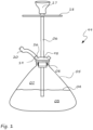
- FIG. 1 The example shown of a water pipe 99 according to the prior art initially has a water container 05 which is filled with water 03 in such a way that an air space 07 remains above the liquid level 04.
- the water container 05 is closed with a closure head 98.
- the closure head 98 is releasably and sealingly connected to the water container 05 by means of a sealing element 08.
- the closure head 98 can be positively connected to the water container 05, for example screwed.
- the closure head 98 can be made in several parts.
- a smoke pipe 06 extends through the closure head 98 and opens into the water 03 with its lower end in the water container 05 below the liquid level 04.
- the smoke pipe 06 is provided with a tobacco head 17 on which glowing coal and the tobacco to be vaporized are held.
- a smoke connection 19 and a smoke hose 20 are arranged on the closure head 98 in a smoke hose connection recess (first recess) 26, which extends through the closure head 98 into the air space 07. If a user now sucks on the smoke hose 20, he creates a negative pressure in the water container 05, more precisely in the air space 07, through which air enriched with the evaporated tobacco aromas flows through Smoke pipe 06 and the water 03 are sucked in and cooled, cleaned, calmed and moistened and supplied to the user through the smoke hose 20.
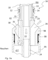
- closure head 98 which is sealingly attached to a water container 05 by means of a sealing element 08.
- the closure head 98 has a through opening 22.
- a two-part smoke pipe 23 and 24 is attached to this opening, the upper smoke pipe 23 being screwed into the upper opening and the lower smoke pipe 24 being screwed into the lower opening.
- a tobacco head 17 is attached to the upper end of the upper smoke pipe 23; the lower smoke pipe 24 opens into the liquid in the water container 05.
- One or more smoke hose connection recesses 26 are arranged in the closure head 98.
- the smoke hose connection recesses 26 open into the inner air space 07.
- valve arrangements (not shown) can be provided in the smoke hose connection recesses 26.
- One or more second recesses 31 are arranged in the closure head 98 for the air-permeable connection between the air space 07 and the outside of the closure head 98.
- a valve arrangement 30 in the form of a check valve is provided in every second recess 31.
- a cladding tube 10 encloses the smoke pipe 23 in such a way that an air-permeable annular space 32 is formed between the smoke pipe 23 and the cladding pipe 10.
- the second recess 31 opens into the annular space 32.
- a third recess 15 creates an air-permeable connection between the annular space 32 and the ambient air.
- the third recess 15 can be arranged in the cladding tube 10 or a cladding tube vent 11.
- the smoke exits the air space 07 via the valve arrangement 30, the second recess 31, the annular space 32 and the third recess 15 into the ambient air.
- a valve device 16 is arranged between the cladding tube 10 and the closure head 98, consisting of a valve housing 02 and a valve body 12.
- the valve housing 02 has one or more third recesses 15.
- the valve body 12 is arranged to be displaceable and / or rotatable relative to the valve housing 02. By changing the position of the valve body 12, several switching positions can be selected.
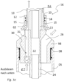
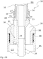
- the valve body 12 can have one or more locking sealing and locking elements 14, for example O-rings made of rubber.
- the valve body 12 can have one or more contours 13 for specifically directing the air flow.
- the valve body 12 may have one or more openings to regulate air flow.
- the openings can have different sizes, e.g. diameters, and shapes.
- the openings can preferably be holes, but for example an oval or angular or slot-like shape is also possible. For example, by rotating the valve body 12, different sizes or shapes can be selected by the user.
- the valve housing 02 of the valve device 16 can be designed in one piece with the cladding tube 10 or as a separate component.
- the Figures 3b to 3e show different switching positions of the valve device 16.
Description
Die Erfindung betrifft ein Ventilsystem für eine Wasserpfeife und eine Wasserpfeife nach dem Oberbegriff der unabhängigen Patentansprüche.The invention relates to a valve system for a hookah and a hookah according to the preamble of the independent claims.
Wasserpfeifen mit Ventilsystemen sind aus dem Stand der Technik beispielsweise aus
Wasserpfeifen, auch Shisha oder Hookah genannt, bestehen üblicherweise aus einem Wasserbehälter, der sogenannten Bowl, und einem Verschlusskopf, der auf dem Wasserbehälter befestigt wird. Am Verschlusskopf ist ein Rauchrohr befestigt, an dessen oberen Ende ein Tabakkopf angeordnet ist, auf dem zusammen mit der glühenden Kohle Tabak verbrannt bzw. verdampft wird. Das Rauchrohr erstreckt sich durch den Verschlusskopf in den Wasserbehälter und mündet mit seinem unteren Ende unterhalb eines Wasserspiegels in den Wasserbehälter. Weiter ist am Verschlusskopf eine Anschlussmöglichkeit für mindestens einen Rauchschlauch vorgesehen, der über eine entsprechende Ausnehmung in den im Wasserbehälter zwischen Kopf und dem Flüssigkeitsspiegel vorgesehenen Luftraum mündet. Beim Ansaugen durch einen Benutzer durch den Rauchschlauch wird in einem im Wasserbehälter vorgesehen Luftraum ein Unterdruck erzeugt, durch den durch das Rauchrohr Tabakrauch angesogen und beim Durchgang durch die Flüssigkeit gereinigt, gekühlt und befeuchtet wird.Water pipes, also called shisha or hookah, usually consist of a water container, the so-called bowl, and a closure head that is attached to the water container. A smoke tube is attached to the closure head, at the upper end of which a tobacco head is arranged, on which tobacco is burned or vaporized together with the glowing coal. The smoke pipe extends through the closure head into the water tank and opens into the water tank with its lower end below a water level. Furthermore, a connection option for at least one smoke hose is provided on the closure head, which opens via a corresponding recess into the air space provided in the water container between the head and the liquid level. When a user sucks in through the smoke hose, a negative pressure is created in an air space provided in the water container Tobacco smoke is sucked in through the smoke pipe and is cleaned, cooled and humidified as it passes through the liquid.
Es ist dabei von Bedeutung, dass der Verschluss den Wasserbehälter vollständig abdichtet, da sonst Nebenluft eingesogen wird und die Wasserpfeife nicht mehr richtig "zieht".It is important that the closure completely seals the water container, otherwise secondary air will be sucked in and the water pipe will no longer "pull" properly.
Bekannte Verschlüsse sind beispielsweise nach Art eines Schraub- oder Steckverschlusses ausgebildet, und haben Anschlussöffnungen für mehrere Rauchschläuche.Known closures are, for example, designed in the manner of a screw or plug-in closure and have connection openings for several smoke hoses.
In bekannter Weise mündet die Anschlussöffnung für den Rauchschlauch mittelbar oder unmittelbar über eine Ausnehmung in den Wasserbehälter. Um insbesondere bei einer Anordnung von mehreren Anschlussöffnungen für jeweils einen Rauchschlauch zu verhindern, dass durch die nicht genutzten Anschlussöffnungen unerwünschte Nebenluft gezogen wird, kann in der Ausnehmung oder den Ausnehmungen jeweils eine Ventilanordnung nach Art eines Rückschlagventils vorgesehen sein. Dabei kann die Ventilanordnung einen schwerkraft- und/oder federkraftbeaufschlagten Ventilkörper aufweisen, der an einen stirnseitig in oder an der Ausnehmung lösbar befestigbaren Ventilsitz zur dichtenden Anlage bringbar ist. Durch Lösen des Ventilsitzes kann die Ventilanordnung bzw. zumindest der Ventilkörper nach Bedarf entfernt, eingesetzt oder getauscht werden.In a known manner, the connection opening for the smoke hose opens directly or indirectly into the water container via a recess. In order to prevent unwanted secondary air from flowing through the unused connection openings, particularly when there are several connection openings for one smoke hose each is pulled, a valve arrangement in the manner of a check valve can be provided in the recess or recesses. The valve arrangement can have a valve body subjected to gravity and/or spring force, which can be brought into sealing contact with a valve seat which can be detachably fastened in or on the recess on the front side. By loosening the valve seat, the valve arrangement or at least the valve body can be removed, inserted or replaced as required.
Um insbesondere während der Benutzung der Wasserpfeife Frischluft in den Luftraum des Wasserbehälters mittels eines der Rauchschläuche einblasen zu können, beispielsweise zur Absenkung der Rauchtemperatur, wird üblicherweise das zugehörige Rückschlagventil des Rauchanschlusses entfernt oder durch eine Ventil-Vorrichtung umgangen. Die eingeblasene Luft entweicht durch die Rückschlagventile der Anschlüsse der weiteren Rauchschläuche. Ebenso sind Ausblasöffnungen mit Rückschlagventilen vorgesehen, die einen Luftdurchgang von der Bowl zur Umgebungsluft ermöglichen und das Ansaugen von Umgebungsluft in die Bowl sperren. Der Öffnungsdruck der Rückschlagventile der Ausblasöffnungen ist geringer als der notwendige Öffnungsdruck der Rückschlagventile der Rauchanschlüsse. Die Ausblasluft tritt aus den Ausblasöffnungen am Verschlusskopf an die Umgebungsluft aus.In order to be able to blow fresh air into the air space of the water container using one of the smoke hoses, particularly while using the water pipe, for example to lower the smoke temperature, the associated check valve of the smoke connection is usually removed or bypassed by a valve device. The blown-in air escapes through the check valves in the connections of the other smoke hoses. Exhaust openings with check valves are also provided, which allow air to pass from the bowl to the ambient air and block the suction of ambient air into the bowl. The opening pressure of the check valves of the exhaust openings is lower than the necessary opening pressure of the check valves of the smoke connections. The blow-out air exits the blow-out openings on the closure head into the ambient air.
Um die Ausblasluft auch an anderen Stellen ausströmen zu lassen um das Ausströmverhalten zu beeinflussen, kann das Rauchrohr von einem Hüllrohr umgeben sein. Zwischen Hüllrohr und Rauchrohr wird ein offener Ringraum gebildet. Die Ausblasöffnungen münden in den Ringraum. An einer oder mehreren Stellen des Hüllrohres sind Ausnehmungen eingebracht. Aus diesen Ausnehmungen tritt die Ausblasluft an die Umgebungsluft. Das Hüllrohr kann mehrteilig aus Rohrabschnitten und Hüllrohrausströmern gestallten sein. Hüllrohre ohne Ausnehmungen und Hüllrohrausströmer mit Ausnehmungen sind kombiniert montierbar. Durch die unterschiedliche Anordnung der Hüllrohre und Hüllrohrausströmer ist die Art und Position der Ausströmung an die Umgebungsluft vorgebbar. Es können gleiche und unterschiedliche Hüllrohrausströmer verwendet werden. Hüllrohre und Hüllrohrausströmer sind in verschiedenen Lagen und Anzahl kombinierbar. Die Hüllrohre und Hüllrohrausströmer sind mit dem Rauchrohr und dem Verschlusskopf formschlüssig verbunden, vorzugsweise verschraubt in Art eines Zugankers. Die Demontage und Montage der Bauteile ist im Betrieb nicht problemlos und sicher möglich, da die heißen Bauteile (Tabakkopf, Rauchrohr, Hüllrohr, Hüllrohrausströmer) demontiert und montiert werden müssten.In order to allow the exhaust air to flow out at other points in order to influence the outflow behavior, the smoke pipe can be surrounded by a cladding pipe. An open annular space is formed between the cladding tube and the smoke tube. The exhaust openings open into the annular space. Recesses are made at one or more points in the cladding tube. The blow-out air exits these recesses into the ambient air. The cladding tube can be designed in several parts from pipe sections and cladding tube outlets. Sheath tubes without recesses and sheath tube vents with recesses can be installed in combination. The type and position of the outflow to the ambient air can be specified due to the different arrangement of the cladding tubes and cladding tube vents. The same and different cladding tube vents can be used. Sheathing tubes and sheathing tube vents can be combined in different positions and numbers. The cladding tubes and cladding tube vents are positively connected to the smoke pipe and the closure head, preferably screwed in the manner of a tie rod. The disassembly and assembly of the components is not possible easily and safely during operation, as the hot components (tobacco head, smoke tube, cladding tube, cladding tube vent) would have to be dismantled and assembled.
Ausgehend von diesem Stand der Technik ist es eine Aufgabe der vorliegenden Erfindung, ein Ventilsystem für eine Wasserpfeife zu liefern, das einfach bedienbar ist und das unterschiedliches Ausströmen von Ausblasluft an die Umgebungsluft ermöglicht. Die Verstellung des Ventilsystems soll vorzugsweise durch manuellen Eingriff erfolgen und vorzugsweise auch im Betrieb der Wasserpfeife möglich sein, ohne das Bauteile demontiert oder montiert werden. Das Ventilsystem ist mit dem Hüllrohr kombinierbar. Es kann ein Ventilsystem bestehend aus ein oder mehreren Ausströmventilen mit dem Hüllrohr und dem Rauchrohr kombiniert werden. Jedes Ausströmventil besitzt mehrere Schaltstellungen. Beim Einsatz mehrerer Ausströmventile sind diese unabhängig voneinander einstellbar. Die Anzahl der einstellbaren Variationen ergibt sich aus der Multiplikation der Schaltstellungsanzahl der einzelnen Ausströmventile.Based on this prior art, it is an object of the present invention to provide a valve system for a water pipe that is easy to operate and that enables different outflows of blow-out air to the ambient air. The valve system should preferably be adjusted by manual intervention and should preferably also be possible while the water pipe is in operation, without components having to be dismantled or assembled. The valve system can be combined with the cladding tube. A valve system consisting of one or more outflow valves can be combined with the cladding pipe and the smoke pipe. Each outflow valve has several switching positions. If several outflow valves are used, they can be adjusted independently of one another. The number of adjustable variations results from multiplying the number of switching positions of the individual outflow valves.
Diese Aufgabe wird durch ein Ventilsystem nach der Lehre des Anspruchs 1 gelöst.This task is solved by a valve system according to the teaching of claim 1.
Vorteilhafte Ausgestaltungen der Erfindung sind Gegenstand der Unteransprüche.Advantageous embodiments of the invention are the subject of the subclaims.
Eine Ausführungsform der Erfindung betrifft ein Ventilsystem, mit dem das Ausströmen von Luft aus dem Ringraum zwischen Rauchrohr und Hüllrohr gesteuert werden kann. Das Ventilsystem sitzt oberhalb des Verschlusskopfes vorzugsweise am unteren und oberen Ende des Rauchrohres. Das Ventilsystem besitzt mehrere Schaltstellungen und ist vorzugsweise manuell bedienbar, ohne das eine Demontage und Montage von Bauteilen notwendig ist.One embodiment of the invention relates to a valve system with which the outflow of air from the annular space between the smoke pipe and the cladding pipe can be controlled. The valve system is located above the closure head, preferably at the lower and upper ends of the smoke pipe. The valve system has several switching positions and can preferably be operated manually, without the need to disassemble and assemble components.
Das Ventilsystem für eine Wasserpfeife gemäß einer Ausführungsform der vorliegenden Erfindung weist mindestens eine Ventileinrichtung mit mehreren Schaltstellungen auf, die Art und Richtung der Ausblasluft steuert.The valve system for a water pipe according to an embodiment of the present invention has at least one valve device with several switching positions that controls the type and direction of the blow-out air.
Die Ausströmventile des Ventilsystems sind vorzugsweise am Hüllrohr oberhalb des Verschlusskopfes angeordnet und bestehen vorzugsweise aus einem Ventilgehäuse und einem Ventilkörper. Die Ausnehmungen der Ausströmventile münden vom Ringraum zwischen Rauchrohr und Hüllrohr in die Umgebungsluft. Die Ausströmventile besitzen mehrere Schaltstellungen. Die Ausnehmungen der Ausströmventile können verschlossen oder geöffnet werden. Bei geöffneten Ausnehmungen kann das Ausströmen der Ausblasluft in der Richtung mittels mehrerer Schaltstellungen variiert werden.The outflow valves of the valve system are preferably arranged on the cladding tube above the closure head and preferably consist of a valve housing and a valve body. The recesses of the outflow valves open into the ambient air from the annular space between the smoke pipe and the cladding pipe. The outflow valves have several switching positions. The recesses in the outflow valves can be closed or opened. When the recesses are open, the direction of the blow-out air can be varied using several switching positions.
Vorteilhaft für die Variantenzahl ist es, Ausströmventile und Hüllrohr als einzelne Bauteile auszuführen. Diese Bauteile sind dann in mehreren Konfigurationen montierbar.It is advantageous for the number of variants to design the outflow valves and cladding tube as individual components. These components can then be assembled in several configurations.
Wenn gleich es für das Wesen der Erfindung ausreicht, wenn ein Ausströmventil vorgesehen ist, ist es in bevorzugten Ausführungsformen von Vorteil, eine Vielzahl von Ausströmventilen vorzusehen.Although it is sufficient for the essence of the invention if one outflow valve is provided, in preferred embodiments it is advantageous to provide a plurality of outflow valves.
Eine Ausführungsform der Erfindung umfasst ein Ventilsystem für eine Wasserpfeife (99) mit einem Verschlusskopf (98), der an einem Wasserbehälter (05) einer Wasserpfeife (99) befestigbar ist. Der Verschlusskopf umfasst eine, im befestigten Zustand des Verschlusskopfes (98) zum Wasserbehälter gerichtete Unterseite und eine der Unterseite gegenüberliegende Oberseite und eine erste Ausnehmung (26) und einen Rauchschlauchanschluss (19) geeignet um mittels der ersten Ausnehmung (26) eine fluidleitende Verbindung zwischen Wasserbehälter (5) und Umgebung der Wasserpfeife herzustellen und eine zweite Ausnehmung (31) mit einem Ausblasventil (30) geeignet um bei Unterdruck im Wasserbehälter (5) eine fluidleitende Verbindung zwischen der zweiten Ausnehmung (31) und dem Wasserbehälter (5) zu schließen und um bei Überdruck im Wasserbehälter (5) eine fluidleitende Verbindung zwischen dem Wasserbehälter und der Ausnehmung (31) zu öffnen. Das Ventilsystem umfasst außerdem ein an der Unterseite des Verschlusskopfes (98) befestigtes unteres Rauchrohr (24) und ein an der Oberseite des Verschlusskopfes (98) befestigtes oberes Rauchrohr (23) und ein, an der Oberseite des Verschlusskopfes (98) befestigtes und das obere Rauchrohr (23) umgebende, Ventilgehäuse (02) mit einer vom oberen Rauchrohr wegweisenden Außenfläche und ein, an dem Ventilgehäuse (02), befestigten und das obere Rauchrohr (23) umgebende, Hüllrohr (10) und einen, an dem Ventilgehäuse (02), angeordneten und das Ventilgehäuse (02) umgebenden, Ventilkörper (12) mit einer zur Außenfläche des Ventilgehäuse (02) gerichteten Innenfläche und einer dritten Ausnehmung (15), wobei das Ventilgehäuse (02) und das Hüllrohr (10) zwischen dem oberen Rauchrohr (23) und dem Ventilgehäuse (02) und dem Hüllrohr (10) einen Ringraum (32) bilden der mit der zweiten Ausnehmung (31) fluidleitend verbunden ist und wobei die dritte Ausnehmung (15) geeignet ist um eine fluidleitende Verbindung zwischen dem Ringraum (32) und der Umgebung der Wasserpfeife herzustellen und wobei der Ventilkörper (12) derart ausgebildet ist, dass er auch im Betrieb der Wasserpfeife entlang einer äußeren Oberfläche des Ventilgehäuses (02) derart bewegbar ist, dass er mindestens eine Schließstellung und mindestens eine Öffnungsstellung einnehmen kann, wobei der Ventilkörper (12) in der Schließstellung die dritte Ausnehmung (15) zur Umgebung der Wasserpfeife hin verschließt und in der Öffnungsstellung die dritte Ausnehmung (15) zur Umgebung der Wasserpfeife hin derart öffnet dass bei Überdruck im Wasserbehälter (5) über die zweite Ausnehmung (31) und den Ringraum (32) und die dritte Ausnehmung (15) eine fluidleitende Verbindung zwischen dem Wasserbehälter (5) und der Umgebung der Wasserpfeife ausgebildet werden kann.One embodiment of the invention comprises a valve system for a water pipe (99) with a closure head (98) which can be attached to a water container (05) of a water pipe (99). The closure head comprises an underside directed towards the water container when the closure head (98) is in the attached state and an upper side opposite the underside and a first recess (26) and a smoke hose connection (19) suitable for establishing a fluid-conducting connection between the water container by means of the first recess (26). (5) and the surrounding area of the water pipe and a second recess (31) with a blow-out valve (30) suitable for closing a fluid-conducting connection between the second recess (31) and the water container (5) when there is negative pressure in the water container (5). in the event of excess pressure in the water container (5), a fluid-conducting connection between the water container and the recess (31) is opened. The valve system also includes a lower smoke pipe (24) attached to the underside of the closure head (98) and an upper smoke pipe (23) attached to the top of the closure head (98) and one attached to the top of the closure head (98) and the upper one Valve housing (02) surrounding the smoke pipe (23) with an outer surface pointing away from the upper smoke pipe and a cladding pipe attached to the valve housing (02) and surrounding the upper smoke pipe (23). (10) and a valve body (12) arranged on the valve housing (02) and surrounding the valve housing (02) with an inner surface directed towards the outer surface of the valve housing (02) and a third recess (15), the valve housing (02 ) and the cladding tube (10) between the upper smoke pipe (23) and the valve housing (02) and the cladding tube (10) form an annular space (32) which is fluidly connected to the second recess (31) and the third recess (15 ) is suitable for establishing a fluid-conducting connection between the annular space (32) and the surroundings of the water pipe and wherein the valve body (12) is designed such that it can also be moved along an outer surface of the valve housing (02) during operation of the water pipe, that it can assume at least one closed position and at least one open position, the valve body (12) closing the third recess (15) towards the surroundings of the water pipe in the closed position and opening the third recess (15) towards the surroundings of the water pipe in the open position that in the event of excess pressure in the water container (5), a fluid-conducting connection can be formed between the water container (5) and the surroundings of the water pipe via the second recess (31) and the annular space (32) and the third recess (15).
In einer weiteren Ausführungsform des Ventilsystems ist der Ventilkörper (12) derart ausgebildet, dass er eine erste Öffnungsstellung oder eine zweite Öffnungsstellung oder eine dritte Öffnungsstellung einnehmen kann, wobei der Ventilkörper (12) in der ersten Öffnungsstellung die dritte Ausnehmung (15) zur Umgebung der Wasserpfeife hin derart öffnet, dass durch die Verbindung zwischen Wasserbehälter (5) und der Umgebung der Wasserpfeife entweichendes Fluid senkrecht zur Ausnehmung (15) und senkrecht zum Ventilgehäuse (02) entweichen kann und wobei der Ventilkörper (12) in der zweiten Öffnungsstellung die dritte Ausnehmung (15) zur Umgebung der Wasserpfeife hin derart öffnet, dass durch die Verbindung zwischen Wasserbehälter (5) und der Umgebung der Wasserpfeife entweichendes Fluid nach unten entweichen kann und wobei der Ventilkörper (12) in der dritten Öffnungsstellung die dritte Ausnehmung (15) zur Umgebung der Wasserpfeife hin derart öffnet, dass durch die Verbindung zwischen Wasserbehälter (5) und der Umgebung der Wasserpfeife entweichendes Fluid nach oben entweichen kann.In a further embodiment of the valve system, the valve body (12) is designed such that it can assume a first opening position or a second opening position or a third opening position, the valve body (12) in the first opening position opening the third recess (15) to the surroundings The water pipe opens in such a way that fluid escaping through the connection between the water container (5) and the surroundings of the water pipe can escape perpendicular to the recess (15) and perpendicular to the valve housing (02), and the valve body (12) has the third recess in the second opening position (15) opens towards the surroundings of the water pipe in such a way that fluid escaping through the connection between the water container (5) and the surroundings of the water pipe can escape downwards and the valve body (12) in the third opening position opens the third recess (15) to the surroundings The water pipe opens in such a way that fluid escaping through the connection between the water container (5) and the area surrounding the water pipe can escape upwards.
In einer weiteren Ausführungsform des Ventilsystems ist der Ventilkörper (12) derart bewegbar ist dass er entlang der Außenfläche des Ventilgehäuses (02) vertikal verschiebbar ist.In a further embodiment of the valve system, the valve body (12) is movable in such a way that it can be displaced vertically along the outer surface of the valve housing (02).
In einer weiteren Ausführungsform des Ventilsystems ist der Ventilkörper (12) derart bewegbar ist dass er entlang der Außenfläche des Ventilgehäuses (02) drehbar ist.In a further embodiment of the valve system, the valve body (12) is movable such that it can be rotated along the outer surface of the valve housing (02).
In einer weiteren Ausführungsform des Ventilsystems weist das Ventilgehäuse (02) auf seiner Außenfläche und der Ventilkörper (12) auf seiner Innenfläche jeweils mindestens eine umlaufende Nut auf in der ein Dicht-und-Rastelement (14) angeordnet ist.In a further embodiment of the valve system, the valve housing (02) has at least one circumferential groove on its outer surface and the valve body (12) on its inner surface, in which a sealing and locking element (14) is arranged.
In einer weiteren Ausführungsform des Ventilsystems ist das Dicht-und-Rastelement (14) ein O-Ring.In a further embodiment of the valve system, the sealing and locking element (14) is an O-ring.
In einer weiteren Ausführungsform des Ventilsystems sind mindestens zwei Ventilgehäuse (02) und zwei Ventilkörper (12) vertikal übereinander und das obere Rauchrohr umgebend angeordnet.In a further embodiment of the valve system, at least two valve housings (02) and two valve bodies (12) are arranged vertically one above the other and surrounding the upper smoke pipe.
Eine weitere Ausführungsform umfasst eine Wasserpfeife (99) mit einem Wasserbehälter (05), einem, an dem Wasserbehälter (05) befestigten, Ventilsystem nach einem der Ansprüche 1 bis 9, einem, an dem Rauschlauchanschluss (19) des Verschlusskopfes (98) befestigten Rauchschlauch (20), einem, an dem oberen Rauchrohr (23) befestigten Tabakkopf (17) und einem unterhalb des Tabakkopfes (17) angeordneten Kohleteller (18).A further embodiment comprises a water pipe (99) with a water container (05), a valve system according to one of claims 1 to 9 attached to the water container (05), a smoke hose attached to the smoke hose connection (19) of the closure head (98). (20), a tobacco head (17) attached to the upper smoke pipe (23) and a charcoal plate (18) arranged below the tobacco head (17).
Im Folgenden wird die Erfindung anhand lediglich Ausführungsbeispiele zeigender Zeichnungen näher erläutert.The invention is explained in more detail below using drawings that only show exemplary embodiments.
Es zeigen:
- Figur 1
- in schematischer nicht maßstäblicher Darstellung den grundsätzlichen Aufbau einer Wasserpfeife
- Figuren 2a und 2b
- ein Ausführungsbeispiel eines Verschlusses mit Hüllrohr und Hüllrohrausströmer.
- Figuren 3a bis 3e
- ein Ausführungsbeispiel eines erfindungsgemäßen Ventil-systems mit einem Ausströmventil mit mehreren Schaltstel-lungen.
- Figur 4
- ein Ausführungsbeispiel eines erfindungsgemäßen Ventil-systems mit zwei Ausströmventilen mit mehreren Schalt-stellungen.
- Figuren 5a und 5b
- ein Ausführungsbeispiel eines erfindungsgemäßen Ventil-systems mit einem Ausströmventil mit mehreren Schaltstel-lungen.
- Figure 1
- in a schematic, not to scale representation of the basic structure of a water pipe
- Figures 2a and 2b
- an embodiment of a closure with cladding tube and cladding tube vent.
- Figures 3a to 3e
- an embodiment of a valve system according to the invention with an outflow valve with several switching positions.
- Figure 4
- an embodiment of a valve system according to the invention with two outflow valves with several switching positions.
- Figures 5a and 5b
- an embodiment of a valve system according to the invention with an outflow valve with several switching positions.
Das in der
Das in den
Der Verschlusskopf 98 weist eine durchgehende Öffnung 22 auf. In diese Öffnung ist ein zweiteiliges Rauchrohr 23 und 24 befestigt, wobei das obere Rauchrohr 23 in die obere Öffnung und das untere Rauchrohr 24 in die untere Öffnung eingeschraubt ist. Am oberen Ende des oberen Rauchrohrs 23 ist ein Tabakkopf 17 angebracht; das untere Rauchrohr 24 mündet in die im Wasserbehälter 05 befindliche Flüssigkeit.The
Im Verschlusskopf 98 sind ein oder mehrere Rauchschlauchanschlussausnehmungen 26 (erste Ausnehmungen), vorzugsweise im Winkel von jeweils etwa 45° zur Rauchrohrachse, angeordnet. Die Rauchschlauchanschluss-ausnehmungen 26 münden in den inneren Luftraum 07.One or more smoke hose connection recesses 26 (first recesses), preferably at an angle of approximately 45° to the smoke pipe axis, are arranged in the
Im Falle mehrerer Rauchschlauchanschlussausnehmungen 26 können in den Rauchschlauchanschlussausnehmungen 26 nicht dargestellte Ventilanordnungen vorgesehen sein.In the case of several smoke hose connection recesses 26, valve arrangements (not shown) can be provided in the smoke hose connection recesses 26.
Im Verschlusskopf 98 sind ein oder mehrere zweite Ausnehmungen 31 zur luftdurchlässigen Verbindung zwischen Luftraum 07 und Außenseite des Verschlusskopfes 98 angeordnet. In jeder zweiten Ausnehmung 31 ist eine Ventilanordnung 30 in Art eines Rückschlagventils vorgesehen.One or more
Ein Hüllrohr 10 umhüllt das Rauchrohr 23 derart, dass zwischen Rauchrohr 23 und Hüllrohr 10 ein luftdurchlässiger Ringraum 32 ausgebildet wird. Die zweite Ausnehmung 31 mündet in den Ringraum 32. Eine dritte Ausnehmung 15 stellt eine luftdurchlässige Verbindung zwischen Ringraum 32 und der Umgebungsluft her. Die dritte Ausnehmung 15 kann im Hüllrohr 10 oder einem Hüllrohrausströmer 11 angeordnet sein.A
Wird Luft in die Rauchschlauchanschlussausnehmungen 26 eingeblasen, tritt der Rauch aus dem Luftraum 07 über die Ventilanordnung 30, die zweite Ausnehmung 31, den Ringraum 32 und die dritte Ausnehmung 15 an die Umgebungsluft aus.If air is blown into the smoke hose connection recesses 26, the smoke exits the
Das in der
Zwischen Hüllrohr 10 und Verschlusskopf 98 ist eine Ventileinrichtung 16 angeordnet, bestehend aus einem Ventilgehäuse 02 und einem Ventilkörper 12. Das Ventilgehäuse 02 hat ein oder mehrere dritte Ausnehmungen 15. Der Ventilkörper 12 ist zum Ventilgehäuse 02 verschiebbar und / oder verdrehbar angeordnet. Durch die Lageänderung des Ventilkörpers 12 sind mehrere Schaltstellungen wählbar. Der Ventilkörper 12 kann ein oder mehrere rastende Dicht-und-Rastelemente 14, beispielsweise O-Ringe aus Gummi, aufweisen. Der Ventilkörper 12 kann ein oder mehrere Konturen 13 zum gezielten Lenken der Luftströmung aufweisen. Der Ventilkörper 12 kann ein oder mehrere Öffnungen aufweisen um die Luftströmung zu regulieren. Die Öffnungen können unterschiedliche Größen, z.B. Durchmesser, und Formen aufweisen. Die Öffnungen können vorzugsweise Löcher sein, aber beispielsweise auch eine ovale oder eckige oder schlitzartige Form ist möglich. Beispielsweise durch Drehung des Ventilkörpers 12 können verschiedene Größen oder Formen durch den Benutzer ausgewählt werden.A
Das Ventilgehäuse 02 der Ventileinrichtung 16 kann einteilig mit dem Hüllrohr 10 oder als separates Bauteil ausgeführt werden.The
Die
Das in den
Das in den
- 0202
- VentilgehäuseValve housing
- 0303
- WasserWater
- 0404
- Flüssigkeitsspiegelliquid level
- 0505
- Wasserbehälter (Bowl)Water container (bowl)
- 0606
- Rauchrohr, mehrteiligSmoke pipe, multi-part
- 0707
- Luftraumairspace
- 0808
- DichtelementSealing element
- 0909
- SperrventilanordnungCheck valve arrangement
- 1010
- Hüllrohrcladding tube
- 1111
- Hüllrohrausströmercladding tube vent
- 12 12'12 12'
- VentilkörperValve body
- 1313
- Konturcontour
- 1414
- Dicht-und-RastelementSealing and locking element
- 1515
- dritte Ausnehmungthird recess
- 16 16'16 16'
- VentileinrichtungValve device
- 1717
- TabakkopfTobacco head
- 1818
- KohletellerCharcoal plate
- 1919
- RauchschlauchanschlussSmoke hose connection
- 2020
- Rauchschlauchsmoke hose
- 2222
- Öffnung für RauchrohrOpening for smoke pipe
- 2323
- Oberes RauchrohrUpper smoke pipe
- 2424
- Unteres RauchrohrLower smoke pipe
- 2626
- erste Ausnehmung (Rauschschlauchanschlussausnehmung)first recess (noise hose connection recess)
- 3030
- AusblasventilBlow-out valve
- 3131
- zweite Ausnehmungsecond recess
- 3232
- RingraumAnnular space
- 9898
- VerschlusskopfBolt head
- 9999
- WasserpfeifeHookah
Claims (10)
- A valve system for a water pipe (99), comprising:a closure head (98) capable of being attached to a water container (5) of a water pipe (99), said closure head including:a bottom side facing the water container when the closure head (98) is attached, anda top side opposing the bottom side, anda first recess (26), anda smoke hose connection (19) being adapted to establish a fluid-conducting connection between the water container (5) and the surroundings of the water pipe by means of the first recess (26), anda second recess (31) having a blow-out valve (30) being adapted to close a fluid-conducting connection between the second recess (31) and the water container (5) when there is a negative pressure in the water container (5), and to open a fluid-conducting connection between the water container (5) and the recess (31) when there is excess pressure in the water container (5),a lower smoke pipe (24) attached to the bottom side of the closure head (98), andan upper smoke pipe (23) attached to the top side of the closure head (98), anda valve housing (02) attached to the top side of the closure head (98) and surrounding the upper smoke pipe (23), having an outer surface facing away from the upper smoke pipe, anda cladding tube (10) attached to the valve housing (02) and surrounding the upper smoke pipe (23), anda valve body (12) arranged on the valve housing (02) and surrounding the valve housing (02), having an inner surface directed towards the outer surface of the valve housing (02) and a third recess (15),wherein the valve housing (02) and the cladding tube (10) form an annular space (32) between the upper smoke tube (23) and the valve housing (02) and the cladding tube (10), said annular space (32) being connected to the second recess (31) in a fluid-conducting manner, andwherein the third recess (15) is adapted to establish a fluid-conducting connection between the annular space (32) and the surroundings of the water pipe, andwherein the valve body (12) is designed such that it is capable of being moved along an outer surface of the valve housing (02) even during operation of the water pipe in such a way for it to be able to assume at least one closed position and at least one open position, said valve body (12), when in the closed position, closing the third recess (15) towards the surroundings of the water pipe and, when in the open position, opening the third recess (15) towards the surroundings of the water pipe in such a way that, in the event of excess pressure in the water container (5), a fluid-conducting connection may be formed between the water container (5) and the surroundings of the water pipe, via the second recess (31) and the annular space (32 ) and the third recess (15).
- The valve system for a water pipe (99) according to claim 1, wherein the valve body (12) is designed in a manner for it to be able to assume either one of a first opening position, a second opening position, or a third opening position,wherein the valve body (12), when in the first opening position, opens the third recess (15) towards the surroundings of the water pipe in a manner for fluid escaping through the connection between the water container (5) and the surroundings of the water pipe to be able to escape perpendicular to the recess (15) and perpendicular to the valve housing (02), andwherein the valve body (12), when in the second opening position, opens the third recess (15) towards the surroundings of the water pipe in a manner for fluid escaping through the connection between the water container (5) and the surroundings of the water pipe to be able to escape downwards, andwherein the valve body (12), when in the third opening position, opens the third recess (15) towards the surroundings of the water pipe in a manner for fluid escaping through the connection between the water container (5) and the surroundings of the water pipe to escape upwards.
- The valve system for a water pipe (99) according to any one of claims 1 or 2, wherein the valve body (12) is capable of being moved such that it is vertically displaceable along the outer surface of the valve housing (02).
- The valve system for a water pipe (99) according to any one of claims 1 to 3, wherein the valve body (12) is capable of being moved to be rotatable along the outer surface of the valve housing (02).
- The valve system for a water pipe (99) according to claim 4, wherein the valve body (12) has at least two openings of different sizes to regulate air flow.
- The valve system for a water pipe (99) according to claim 5, wherein the openings have at least one of a round, an oval, a slot-like or a square shape.
- The valve system for a water pipe (99) according to claim 3, wherein the valve housing (02) on the outer surface thereof and the valve body (12) on the inner surface thereof each have at least one circumferential groove in which a sealing and locking element (14) is arranged.
- The valve system for a water pipe (99) according to claim 7, wherein the sealing and locking element (14) is an O-ring.
- The valve system for a water pipe (99) according to any one of claims 1 to 8, wherein at least two valve housings (02) and two valve bodies (12) are arranged vertically one on top of the other while surrounding the upper smoke pipe.
- The water pipe (99) including a water container (05), a valve system according to any one of claims 1 to 9 which is attached to the water container (05), a smoke hose (20) attached to the smoke hose connection (19) of the closure head (98), a tobacco head (17) attached to the upper smoke pipe (23) and a charcoal plate (18) arranged below the tobacco head (17).
Applications Claiming Priority (1)
| Application Number | Priority Date | Filing Date | Title |
|---|---|---|---|
| DE202021105847.1U DE202021105847U1 (en) | 2021-10-26 | 2021-10-26 | Valve system for a water pipe and water pipe |
Publications (2)
| Publication Number | Publication Date |
|---|---|
| EP4173499A1 EP4173499A1 (en) | 2023-05-03 |
| EP4173499B1 true EP4173499B1 (en) | 2024-03-13 |
Family
ID=78823372
Family Applications (1)
| Application Number | Title | Priority Date | Filing Date |
|---|---|---|---|
| EP22203591.7A Active EP4173499B1 (en) | 2021-10-26 | 2022-10-25 | Valve system for a hookah |
Country Status (3)
| Country | Link |
|---|---|
| EP (1) | EP4173499B1 (en) |
| CN (1) | CN219353045U (en) |
| DE (1) | DE202021105847U1 (en) |
Family Cites Families (3)
| Publication number | Priority date | Publication date | Assignee | Title |
|---|---|---|---|---|
| US4133318A (en) * | 1977-06-20 | 1979-01-09 | Ronald Gross | Water pipe |
| DE202019001094U1 (en) * | 2019-03-06 | 2019-05-01 | Schmidt Innovations GmbH | Valve system for a hookah |
| DE202019106795U1 (en) * | 2019-12-05 | 2019-12-16 | Schmidt Innovations GmbH | Valve system for a hookah |
-
2021
- 2021-10-26 DE DE202021105847.1U patent/DE202021105847U1/en active Active
-
2022
- 2022-10-25 CN CN202222818257.0U patent/CN219353045U/en active Active
- 2022-10-25 EP EP22203591.7A patent/EP4173499B1/en active Active
Also Published As
| Publication number | Publication date |
|---|---|
| CN219353045U (en) | 2023-07-18 |
| DE202021105847U1 (en) | 2021-11-12 |
| EP4173499A1 (en) | 2023-05-03 |
Similar Documents
| Publication | Publication Date | Title |
|---|---|---|
| DE4109337A1 (en) | CAPLESS VEHICLE REFUELING DEVICE | |
| DE102014009231B4 (en) | Shut-off filter apparatus | |
| DE202020104097U1 (en) | Valve system for a water pipe | |
| DE202018101974U1 (en) | Base body for a hookah | |
| EP3303893B1 (en) | Quick-coupling device | |
| DE102005034812A1 (en) | Air intake apparatus for vehicle fuel system, has fuel inlet space partially isolated from outside of vehicle body, such that air which is more pure than air outside of body flows into air intake space and then to air filter | |
| DE202019001094U1 (en) | Valve system for a hookah | |
| DE102013002857A1 (en) | plumbing fixture | |
| DE202019101422U1 (en) | Valve system for a hookah | |
| EP4173499B1 (en) | Valve system for a hookah | |
| DE202017002153U1 (en) | Valve system for a water pipe | |
| DE202019106795U1 (en) | Valve system for a hookah | |
| AT399212B (en) | ADAPTER ARMATURE FOR SELECTIVE CONNECTION OF A RADIATOR | |
| DE202019102325U1 (en) | Valve system for a hookah | |
| DE4210807C2 (en) | Air outlet | |
| DE202017003659U1 (en) | Valve system for a hookah | |
| DE2650655C3 (en) | ||
| EP1657215A1 (en) | Piggable distribution device | |
| DE102021122142B3 (en) | Hookah with selectable smoke outlet location | |
| DE19703082A1 (en) | Through-flow regulator for sick-child incubator system | |
| DE602006000355T2 (en) | Automatic bleed valve | |
| DE202022102444U1 (en) | Valve system for a hookah | |
| DE168230C (en) | ||
| DE202018103364U1 (en) | hookah | |
| DE102013002235A1 (en) | Air intake device for a sanitary shower |
Legal Events
| Date | Code | Title | Description |
|---|---|---|---|
| PUAI | Public reference made under article 153(3) epc to a published international application that has entered the european phase |
Free format text: ORIGINAL CODE: 0009012 |
|
| STAA | Information on the status of an ep patent application or granted ep patent |
Free format text: STATUS: THE APPLICATION HAS BEEN PUBLISHED |
|
| AK | Designated contracting states |
Kind code of ref document: A1 Designated state(s): AL AT BE BG CH CY CZ DE DK EE ES FI FR GB GR HR HU IE IS IT LI LT LU LV MC ME MK MT NL NO PL PT RO RS SE SI SK SM TR |
|
| STAA | Information on the status of an ep patent application or granted ep patent |
Free format text: STATUS: REQUEST FOR EXAMINATION WAS MADE |
|
| 17P | Request for examination filed |
Effective date: 20230710 |
|
| RBV | Designated contracting states (corrected) |
Designated state(s): AL AT BE BG CH CY CZ DE DK EE ES FI FR GB GR HR HU IE IS IT LI LT LU LV MC ME MK MT NL NO PL PT RO RS SE SI SK SM TR |
|
| GRAP | Despatch of communication of intention to grant a patent |
Free format text: ORIGINAL CODE: EPIDOSNIGR1 |
|
| STAA | Information on the status of an ep patent application or granted ep patent |
Free format text: STATUS: GRANT OF PATENT IS INTENDED |
|
| INTG | Intention to grant announced |
Effective date: 20230925 |
|
| GRAS | Grant fee paid |
Free format text: ORIGINAL CODE: EPIDOSNIGR3 |
|
| GRAA | (expected) grant |
Free format text: ORIGINAL CODE: 0009210 |
|
| STAA | Information on the status of an ep patent application or granted ep patent |
Free format text: STATUS: THE PATENT HAS BEEN GRANTED |
|
| AK | Designated contracting states |
Kind code of ref document: B1 Designated state(s): AL AT BE BG CH CY CZ DE DK EE ES FI FR GB GR HR HU IE IS IT LI LT LU LV MC ME MK MT NL NO PL PT RO RS SE SI SK SM TR |
|
| REG | Reference to a national code |
Ref country code: GB Ref legal event code: FG4D Free format text: NOT ENGLISH |
|
| REG | Reference to a national code |
Ref country code: CH Ref legal event code: EP |
|
| REG | Reference to a national code |
Ref country code: DE Ref legal event code: R096 Ref document number: 502022000609 Country of ref document: DE |