EP4171185A1 - Joint d'étanchéité pour matériau d'interface thermique de modules électroniques de puissance - Google Patents
Joint d'étanchéité pour matériau d'interface thermique de modules électroniques de puissance Download PDFInfo
- Publication number
- EP4171185A1 EP4171185A1 EP22202611.4A EP22202611A EP4171185A1 EP 4171185 A1 EP4171185 A1 EP 4171185A1 EP 22202611 A EP22202611 A EP 22202611A EP 4171185 A1 EP4171185 A1 EP 4171185A1
- Authority
- EP
- European Patent Office
- Prior art keywords
- heat exchanger
- gasket
- exchanger assembly
- housing
- power electronics
- Prior art date
- Legal status (The legal status is an assumption and is not a legal conclusion. Google has not performed a legal analysis and makes no representation as to the accuracy of the status listed.)
- Pending
Links
- 239000000463 material Substances 0.000 title claims abstract description 19
- 239000012530 fluid Substances 0.000 claims description 34
- 230000013011 mating Effects 0.000 claims description 7
- 239000004519 grease Substances 0.000 claims description 6
- 239000003507 refrigerant Substances 0.000 claims description 4
- 230000005484 gravity Effects 0.000 claims description 3
- 230000006835 compression Effects 0.000 description 5
- 238000007906 compression Methods 0.000 description 5
- 238000005219 brazing Methods 0.000 description 2
- 230000000295 complement effect Effects 0.000 description 2
- 238000009833 condensation Methods 0.000 description 2
- 230000005494 condensation Effects 0.000 description 2
- 239000013529 heat transfer fluid Substances 0.000 description 2
- 238000000034 method Methods 0.000 description 2
- 238000003466 welding Methods 0.000 description 2
- 229910000838 Al alloy Inorganic materials 0.000 description 1
- 229910000851 Alloy steel Inorganic materials 0.000 description 1
- RYGMFSIKBFXOCR-UHFFFAOYSA-N Copper Chemical compound [Cu] RYGMFSIKBFXOCR-UHFFFAOYSA-N 0.000 description 1
- 229910000881 Cu alloy Inorganic materials 0.000 description 1
- 229910000831 Steel Inorganic materials 0.000 description 1
- 229910052782 aluminium Inorganic materials 0.000 description 1
- XAGFODPZIPBFFR-UHFFFAOYSA-N aluminium Chemical compound [Al] XAGFODPZIPBFFR-UHFFFAOYSA-N 0.000 description 1
- 238000004891 communication Methods 0.000 description 1
- 150000001875 compounds Chemical class 0.000 description 1
- 239000004020 conductor Substances 0.000 description 1
- 238000001816 cooling Methods 0.000 description 1
- 239000010949 copper Substances 0.000 description 1
- 229910052802 copper Inorganic materials 0.000 description 1
- 230000008878 coupling Effects 0.000 description 1
- 238000010168 coupling process Methods 0.000 description 1
- 238000005859 coupling reaction Methods 0.000 description 1
- -1 e.g. Inorganic materials 0.000 description 1
- 239000013536 elastomeric material Substances 0.000 description 1
- 238000001914 filtration Methods 0.000 description 1
- 230000010354 integration Effects 0.000 description 1
- 238000005304 joining Methods 0.000 description 1
- 238000003754 machining Methods 0.000 description 1
- 238000004519 manufacturing process Methods 0.000 description 1
- 229910052751 metal Inorganic materials 0.000 description 1
- 239000002184 metal Substances 0.000 description 1
- 239000007769 metal material Substances 0.000 description 1
- 238000012986 modification Methods 0.000 description 1
- 230000004048 modification Effects 0.000 description 1
- 238000012545 processing Methods 0.000 description 1
- 238000005057 refrigeration Methods 0.000 description 1
- 239000003566 sealing material Substances 0.000 description 1
- 230000035939 shock Effects 0.000 description 1
- 239000007787 solid Substances 0.000 description 1
- 239000010959 steel Substances 0.000 description 1
- 238000012546 transfer Methods 0.000 description 1
- 238000005406 washing Methods 0.000 description 1
- 239000002918 waste heat Substances 0.000 description 1
Images


Classifications
-
- H—ELECTRICITY
- H05—ELECTRIC TECHNIQUES NOT OTHERWISE PROVIDED FOR
- H05K—PRINTED CIRCUITS; CASINGS OR CONSTRUCTIONAL DETAILS OF ELECTRIC APPARATUS; MANUFACTURE OF ASSEMBLAGES OF ELECTRICAL COMPONENTS
- H05K7/00—Constructional details common to different types of electric apparatus
- H05K7/20—Modifications to facilitate cooling, ventilating, or heating
- H05K7/2089—Modifications to facilitate cooling, ventilating, or heating for power electronics, e.g. for inverters for controlling motor
- H05K7/20936—Liquid coolant with phase change
-
- H—ELECTRICITY
- H05—ELECTRIC TECHNIQUES NOT OTHERWISE PROVIDED FOR
- H05K—PRINTED CIRCUITS; CASINGS OR CONSTRUCTIONAL DETAILS OF ELECTRIC APPARATUS; MANUFACTURE OF ASSEMBLAGES OF ELECTRICAL COMPONENTS
- H05K7/00—Constructional details common to different types of electric apparatus
- H05K7/20—Modifications to facilitate cooling, ventilating, or heating
- H05K7/2039—Modifications to facilitate cooling, ventilating, or heating characterised by the heat transfer by conduction from the heat generating element to a dissipating body
- H05K7/20509—Multiple-component heat spreaders; Multi-component heat-conducting support plates; Multi-component non-closed heat-conducting structures
-
- H—ELECTRICITY
- H05—ELECTRIC TECHNIQUES NOT OTHERWISE PROVIDED FOR
- H05K—PRINTED CIRCUITS; CASINGS OR CONSTRUCTIONAL DETAILS OF ELECTRIC APPARATUS; MANUFACTURE OF ASSEMBLAGES OF ELECTRICAL COMPONENTS
- H05K7/00—Constructional details common to different types of electric apparatus
- H05K7/20—Modifications to facilitate cooling, ventilating, or heating
- H05K7/2039—Modifications to facilitate cooling, ventilating, or heating characterised by the heat transfer by conduction from the heat generating element to a dissipating body
- H05K7/20436—Inner thermal coupling elements in heat dissipating housings, e.g. protrusions or depressions integrally formed in the housing
- H05K7/20445—Inner thermal coupling elements in heat dissipating housings, e.g. protrusions or depressions integrally formed in the housing the coupling element being an additional piece, e.g. thermal standoff
-
- H—ELECTRICITY
- H05—ELECTRIC TECHNIQUES NOT OTHERWISE PROVIDED FOR
- H05K—PRINTED CIRCUITS; CASINGS OR CONSTRUCTIONAL DETAILS OF ELECTRIC APPARATUS; MANUFACTURE OF ASSEMBLAGES OF ELECTRICAL COMPONENTS
- H05K7/00—Constructional details common to different types of electric apparatus
- H05K7/20—Modifications to facilitate cooling, ventilating, or heating
- H05K7/2089—Modifications to facilitate cooling, ventilating, or heating for power electronics, e.g. for inverters for controlling motor
- H05K7/20927—Liquid coolant without phase change
Definitions
- the present invention relates to a heat exchange assembly.
- Exemplary embodiments pertain to the art of heat exchangers, and more particularly to an interface for cooling power electronics that are mounted to a heat exchanger.
- Power electronic devices such as motor drives can generate waste heat during operation based on the efficiency of the device. Additionally, when the power electronic devices heat up, their efficiency can degrade adding to the amount of heat they generate. When configured into a refrigeration system, effective thermal integration of these devices can be important aspect to the system's overall efficiency and reliability. Consequently, a goal of the system integrator is to maintain these components within a range of operating temperatures which will maximize the system efficiency. Accordingly, there remains a need in the art for heat exchangers configured to closely integrate with power electronic devices which can maintain optimal temperatures for these components under a variety of load conditions.
- a heat exchanger assembly includes a heat exchanger and a power electronics module mounted to the heat exchanger.
- the power electronics module is thermally coupled to the heat exchanger at a heat sink interface.
- a thermal interface material is arranged between the heat sink interface and a surface of the heat exchanger and a gasket arranged between the heat sink interface and the surface of the heat exchanger.
- the gasket may surround at least a portion of the thermal interface material.
- the gasket may define a boundary that restricts movement of the thermal interface material relative to the heat sink interface and the surface of the heat exchanger.
- the gasket may extend about at least a portion of a periphery of the heat sink interface.
- the gasket may extend about an entire periphery of the heat sink interface.
- the gasket may be compressed to form a seal between the heat sink interface and the surface of the heat exchanger.
- the surface of the heat exchanger may have a substantially planar configuration and the gasket is positioned in overlapping arrangement with the surface.
- the surface of the heat exchanger may have a gasket groove formed therein, the gasket being arranged within the gasket groove.
- the gasket may have a substantially continuous tube-like configuration.
- the gasket may have a substantially planar configuration.
- the thermal interface material may be thermal grease.
- the power electronics module may be mounted in a vertical plane.
- the heat exchanger may comprise: a housing having an inlet and an outlet formed therein; a fluid circuit arranged within the housing and extending between the inlet and the outlet; and a fluid circulating through the fluid circuit.
- the fluid circuit may comprise: an inlet manifold; an outlet manifold; and a plurality of fluid passages connecting the inlet manifold and the outlet manifold.
- At least one of the inlet manifold, the outlet manifold, and the plurality of fluid passages may be formed as a recess formed in the housing.
- the inlet may be disposed below the outlet such that during operation a flow direction of a refrigerant through the inlet manifold and the outlet manifold opposes gravity.
- the housing may comprise a first housing portion and a second housing portion joined along corresponding mating surfaces.
- the first housing portion and the second housing portion may be a plate.
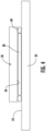
- the heat exchanger 20 includes a housing 22 formed from a heat conductive material, such as a metal material.
- the housing 22 may be formed from any suitable metal, e.g., aluminum, aluminum alloy, steel, steel alloy, copper, copper alloy, or the like.
- the housing 22 is formed from a plurality of housing portions, such as a first housing portion 24, and a second housing portion 26, joined along corresponding mating surfaces to form a seam 28 therebetween.
- first and second housing portions 24, 26 can abut one another along a side and can be joined using any suitable means such as brazing, welding, clamping, compressing, bolting, and the like.
- any suitable means such as brazing, welding, clamping, compressing, bolting, and the like.
- the mating surfaces of the first and second housing portions 24, 26 may be configured to correspond to one another, e.g., to fit together to seal a fluid circuit therebetween (the fluid circuit to be described in more detail below).
- the mating surfaces of the first and second housing portions 24, 26 include precision surfaces formed from a process having highly accurate and precise dimensional control, such as through computer numerical control (CNC) machining process and/or net shape, or near net shape manufacturing process.
- CNC computer numerical control
- a sealing material can be disposed between the first and second housing portions 24, 26 to aide in preventing leakage from the fluid circuit.
- the first and second housing portions 24, 26 can have different thicknesses, measured along the z-axis.
- a thickness of the first housing portion 24 is greater than a thickness of the second housing portion.
- first housing portion 24 and the second housing portion 26 are equal in thickness, or alternatively, where a thickness of the second housing portion 26 is greater than a thickness of the first housing portion 24 are also contemplated.
- each of the first housing portion 24 and the second housing portion 26 is formed as a substantially solid plate.
- one or more of the housing portions 24, 26 has another configuration are also contemplated herein.
- the heat exchanger 20 includes a fluid circuit formed between the first and second housing portions 24, 26.
- the fluid circuit includes a fluid inlet 30 and fluid outlet 32 formed in the housing 22.
- the fluid inlet 30 and the fluid outlet 32 can be any shape, such as in the depth dimension (e.g., in the z-x plane of the attached figure), including the shape of a circle, oval, triangular, square, rectangular, or any simple polygonal shape or portion thereof.
- the perimeter of one or both of the fluid inlet 30 and the fluid outlet 32 can be formed by a recess in at least one or both of the housing portions 24, 26.
- the recess may extend to an edge of a respective housing portion, may be arranged centrally relative to a housing portion, or may overlap with the seam 28 defined between two adjacent housing portions 24, 26.
- the fluid circuit may include a first or inlet manifold 34, a second or outlet manifold 36, and a plurality of fluid passages 38 connecting the first and second manifolds 34, 36.
- the fluid inlet 30 can be configured to connect a first heat transfer fluid (e.g., refrigerant) source, such as a condenser of a vapor compression system for example, to the inlet manifold using any suitable mechanical connection.
- a first heat transfer fluid e.g., refrigerant
- the fluid outlet 32 can be configured to connect a first heat transfer fluid sink, such as an evaporator of a vapor compression system for example, to the outlet manifold using any suitable mechanical connection (e.g., compression coupling, brazing, welding, and the like).
- a first heat transfer fluid sink such as an evaporator of a vapor compression system for example
- the fluid inlet 30 is disposed vertically below the fluid outlet 32 such that during operation of the heat exchanger 20, a flow direction of a refrigerant through the inlet and outlet manifolds 34, 36 opposes gravity.
- One or more of the inlet manifold 34, the outlet manifold 36, and the plurality of fluid passages 38 is formed as a recess in at least one of the first housing portion 24 and the second housing portion 26.
- the inlet manifold 34, the outlet manifold 36, and the plurality of fluid passages 38 are formed as a plurality of connected recesses in at least one housing portion, such as the second housing portion 26 for example.
- the plurality of recesses form the fluid circuit disposed between the first and second housing portions 24, 26 when the housing portions 24, 26 are joined.
- a first housing portion 24 having a plurality of connected recesses can be joined to a flat, second housing portion 26 that does not have any recesses formed therein.
- a first housing portion 24 and a second housing portion 26 can each have a plurality of connected recesses which mirror one another such that when the first and second housing portions 24, 26 are joined, the connected recesses form the fluid circuit.
- the plurality of connected recesses can have any shape in the depth dimension (e.g., as projected onto a z-y plane of the attached figures, into the plate), including semi-circular, semi-oval, triangular, square, rectangular, or any simple polygonal shape or portion thereof.
- the mating surfaces of the first and second housing portions 24, 26 can substantially border the plurality of connected recesses.
- the mating surfaces can include raised or recessed portions, or other engagement features to aid in alignment of the housing portions 24, 26 prior to joining.
- a heat exchanger 20 as described herein can be used, such as in a vapor compression system for example, to cool one or more power electronic modules 50.
- a heat exchanger 20 having one or more power electronics modules 50 mounted thereon may be considered a heat exchanger assembly.
- the term "power electronic module” as used herein can refer to any electronic component which can provide a controlled output power by modulating and/or converting a supplied input power (e.g., a variable frequency drive, power rectifier, power converter, and the like).
- Such a power electronic module 50 can be used to control the speed of a compressor and/or the speed of the fan of a vapor compression system (e.g., chiller) based on various predetermined system conditions.
- one or more power electronic modules 50 are mounted directly to a surface 52 of at least one of the plurality of housing portions, such as first housing portion 24 for example.
- the plurality of power electronics modules 50 are mounted to a vertically oriented surface of the housing 22.
- embodiments where one or more power electronics modules 50 are mounted to a surface of a housing 22 having a non-vertical orientation, such as a horizontal surface for example are also contemplated.
- the power electronic modules 50 may be mounted to the housing 22 of the heat exchanger 20 via one or more fasteners in such a way that facilitates the transfer of thermal energy away from the power electronics module 50.
- the one or more power electronics modules 50 may include a printed circuit board 54 on which various other electrical components (not shown) are mounted (e.g., protection, signal processing, and filtering related components).
- the reliability and life of the one or more power electronics modules 50 can depend upon precluding such electrical components from operating at high temperatures and/or precluding their exposure to thermal shock. Because electrical components inside the power electronics modules 50 can generate a large amount of heat, each of the power electronics modules 50 has a heat sink interface 56 (see FIG. 4 ) which is designed for attachment to a heat sink, such as the heat exchanger 20.
- the heat generated by the power electronics module 50 is at least partially removed through the heat sink interface 56 to keep the one or more power electronics module 50 cooled below its maximum allowable operating temperature (e.g., 150 °C).
- a thermal interface material may be positioned between the heat sink interface 56 of a respective power electronics module 50 and the adjacent surface 52 of the housing 22 configured to receive the power electronics module 50.
- the thermal interface material 58 is a thermal grease or compound having a high thermal conductivity.
- the thermal interface material may include a multiphase material and/or an elastomeric material such as a thermal pad.
- the gravitational forces acting on the thermal grease 58 may cause the thermal grease 58 to move or drip relative to the heat sink interface 56.
- condensation in combination with the gravitational forces may wash the thermal grease 58 away from the heat sink interface 56.
- a gasket 60 is disposed between a portion of the power electronics module 50 and the heat exchanger 20.
- the gasket 60 may extend about at least a portion of the perimeter of the power electronics module 50 at the heat sink interface 56. In the illustrated, non-limiting embodiment, the gasket 60 extends about an entire periphery of the heat sink interface 56. In such embodiments, the dimensions of the gasket 60 are substantially complementary to, or slightly smaller than, the length and width of a respective power electronics module 50.
- the gasket 60 may have a substantially continuous tube-like configuration, or alternatively, may have a substantially planar configuration similar to a washer. However, any suitable configuration of a gasket 60 is contemplated.
- the surface 52 of the heat exchanger 20 configured to receive the power electronics module 50 is generally planar (see FIG. 4 ). As a result, the entirety of the gasket 60 is positioned adjacent to and in overlapping arrangement with the surface 52.
- a gasket groove or recess 62 complementary to the gasket 60 is formed in the surface 52 of the heat exchanger 20. In such embodiments, the gasket 60 is receivable within the gasket groove 62, and therefore only a portion of the gasket 60 protrudes beyond the surface 52 towards the power electronics module 50.
- the gasket 60 When the power electronics module 50 is installed about the surface 52 of the heat exchanger 20, the gasket 60 may be at least partially compressed, thereby forming a seal between the surface 52 of the heat exchanger 20 and a surface of the power electronics module 50 at the heat sink interface 56. Because the gasket 60 extends about at least a portion of the periphery of the heat sink interface 56, the gasket forms a boundary or outer edge to at least a portion of the thermal interface material 58. Accordingly, the seal formed between the power electronics module 50 and the surface 52 of the heat exchanger 20 by the compressed gaskets 60 forms a boundary that restricts movement of the thermal interface material 58 from adjacent to the heat sink interface 56.
- the thermal conductivity between the power electronics module 50 and the heat exchanger 20 is improved, thereby extending the life of the electronic components within the power electronics modules 50.
Landscapes
- Engineering & Computer Science (AREA)
- Microelectronics & Electronic Packaging (AREA)
- Physics & Mathematics (AREA)
- Thermal Sciences (AREA)
- Cooling Or The Like Of Electrical Apparatus (AREA)
- Cooling Or The Like Of Semiconductors Or Solid State Devices (AREA)
Applications Claiming Priority (1)
| Application Number | Priority Date | Filing Date | Title |
|---|---|---|---|
| US202163270888P | 2021-10-22 | 2021-10-22 |
Publications (1)
| Publication Number | Publication Date |
|---|---|
| EP4171185A1 true EP4171185A1 (fr) | 2023-04-26 |
Family
ID=83899824
Family Applications (1)
| Application Number | Title | Priority Date | Filing Date |
|---|---|---|---|
| EP22202611.4A Pending EP4171185A1 (fr) | 2021-10-22 | 2022-10-19 | Joint d'étanchéité pour matériau d'interface thermique de modules électroniques de puissance |
Country Status (3)
| Country | Link |
|---|---|
| US (1) | US20230127088A1 (fr) |
| EP (1) | EP4171185A1 (fr) |
| CN (1) | CN116017930A (fr) |
Citations (3)
| Publication number | Priority date | Publication date | Assignee | Title |
|---|---|---|---|---|
| JP2010092999A (ja) * | 2008-10-07 | 2010-04-22 | Toyota Motor Corp | 放熱構造及び車両用インバータ |
| US8077460B1 (en) * | 2010-07-19 | 2011-12-13 | Toyota Motor Engineering & Manufacturing North America, Inc. | Heat exchanger fluid distribution manifolds and power electronics modules incorporating the same |
| US20160240456A1 (en) * | 2013-12-27 | 2016-08-18 | Mitsubishi Electric Corporation | Semiconductor device |
-
2022
- 2022-10-07 US US17/961,694 patent/US20230127088A1/en active Pending
- 2022-10-19 EP EP22202611.4A patent/EP4171185A1/fr active Pending
- 2022-10-21 CN CN202211291639.0A patent/CN116017930A/zh active Pending
Patent Citations (3)
| Publication number | Priority date | Publication date | Assignee | Title |
|---|---|---|---|---|
| JP2010092999A (ja) * | 2008-10-07 | 2010-04-22 | Toyota Motor Corp | 放熱構造及び車両用インバータ |
| US8077460B1 (en) * | 2010-07-19 | 2011-12-13 | Toyota Motor Engineering & Manufacturing North America, Inc. | Heat exchanger fluid distribution manifolds and power electronics modules incorporating the same |
| US20160240456A1 (en) * | 2013-12-27 | 2016-08-18 | Mitsubishi Electric Corporation | Semiconductor device |
Also Published As
| Publication number | Publication date |
|---|---|
| US20230127088A1 (en) | 2023-04-27 |
| CN116017930A (zh) | 2023-04-25 |
Similar Documents
| Publication | Publication Date | Title |
|---|---|---|
| EP0107706B1 (fr) | Module de refroidissement par tubes de dissipation de chaleur pour des plaques de circuit de grande puissance | |
| EP2031332B1 (fr) | Échangeur de chaleur pour des composants d'électronique de puissance | |
| US10724748B2 (en) | Air-conditioning apparatus | |
| US4712158A (en) | Cooling system for electronic circuit components | |
| US7316263B2 (en) | Cold plate | |
| EP1738128B1 (fr) | Systeme de refroidissement de liquides | |
| WO2011009412A1 (fr) | Ensemble échangeur de chaleur, et machine utilisant cet ensemble | |
| EP4171185A1 (fr) | Joint d'étanchéité pour matériau d'interface thermique de modules électroniques de puissance | |
| US20050225938A1 (en) | Cold plate | |
| WO2015102546A1 (fr) | Enceinte de dispositif refroidi par un liquide | |
| WO2014065696A1 (fr) | Refroidisseur des modules de calcul d'un ordinateur | |
| RU125757U1 (ru) | Охладитель вычислительных модулей компьютера | |
| US20110303403A1 (en) | Flexible Heat Exchanger | |
| EP4175436A1 (fr) | Dissipateur thermique refroidi par réfrigérant pour modules électroniques de puissance | |
| JPWO2016151804A1 (ja) | 電力変換装置 | |
| EP4175434A1 (fr) | Ensemble électronique de puissance refroidi par liquide et air combiné | |
| US11988421B2 (en) | Heat exchanger for power electronics | |
| RU2179768C2 (ru) | Термоэлектрический модуль | |
| EP3575919A1 (fr) | Bloc de dlc destiné à être utilisé dans des composants électroniques et électriques | |
| EP4174433A1 (fr) | Échangeur de chaleur pour électronique de puissance | |
| EP3396288A1 (fr) | Dispositif de réfrigération pour convertisseur de puissance | |
| CN219086060U (zh) | 一种液冷板和电源模块 | |
| CN216873719U (zh) | 一种液冷板 | |
| CN214316098U (zh) | 逆变器冷却系统 | |
| CN215170671U (zh) | 控制器组件及压缩机 |
Legal Events
| Date | Code | Title | Description |
|---|---|---|---|
| PUAI | Public reference made under article 153(3) epc to a published international application that has entered the european phase |
Free format text: ORIGINAL CODE: 0009012 |
|
| STAA | Information on the status of an ep patent application or granted ep patent |
Free format text: STATUS: THE APPLICATION HAS BEEN PUBLISHED |
|
| AK | Designated contracting states |
Kind code of ref document: A1 Designated state(s): AL AT BE BG CH CY CZ DE DK EE ES FI FR GB GR HR HU IE IS IT LI LT LU LV MC ME MK MT NL NO PL PT RO RS SE SI SK SM TR |
|
| P01 | Opt-out of the competence of the unified patent court (upc) registered |
Effective date: 20230527 |
|
| STAA | Information on the status of an ep patent application or granted ep patent |
Free format text: STATUS: REQUEST FOR EXAMINATION WAS MADE |
|
| 17P | Request for examination filed |
Effective date: 20231025 |
|
| RBV | Designated contracting states (corrected) |
Designated state(s): AL AT BE BG CH CY CZ DE DK EE ES FI FR GB GR HR HU IE IS IT LI LT LU LV MC ME MK MT NL NO PL PT RO RS SE SI SK SM TR |
|
| STAA | Information on the status of an ep patent application or granted ep patent |
Free format text: STATUS: EXAMINATION IS IN PROGRESS |
|
| 17Q | First examination report despatched |
Effective date: 20240208 |