EP4170894B1 - Spannungsregelung von hochspannungsgleichstromsystemen - Google Patents
Spannungsregelung von hochspannungsgleichstromsystemen Download PDFInfo
- Publication number
- EP4170894B1 EP4170894B1 EP22202992.8A EP22202992A EP4170894B1 EP 4170894 B1 EP4170894 B1 EP 4170894B1 EP 22202992 A EP22202992 A EP 22202992A EP 4170894 B1 EP4170894 B1 EP 4170894B1
- Authority
- EP
- European Patent Office
- Prior art keywords
- voltage
- generator
- load
- dbr
- regulator
- Prior art date
- Legal status (The legal status is an assumption and is not a legal conclusion. Google has not performed a legal analysis and makes no representation as to the accuracy of the status listed.)
- Active
Links
Images


Classifications
-
- H—ELECTRICITY
- H02—GENERATION; CONVERSION OR DISTRIBUTION OF ELECTRIC POWER
- H02K—DYNAMO-ELECTRIC MACHINES
- H02K19/00—Synchronous motors or generators
- H02K19/16—Synchronous generators
- H02K19/38—Structural association of synchronous generators with exciting machines
-
- H—ELECTRICITY
- H02—GENERATION; CONVERSION OR DISTRIBUTION OF ELECTRIC POWER
- H02P—CONTROL OR REGULATION OF ELECTRIC MOTORS, ELECTRIC GENERATORS OR DYNAMO-ELECTRIC CONVERTERS; CONTROLLING TRANSFORMERS, REACTORS OR CHOKE COILS
- H02P25/00—Arrangements or methods for the control of AC motors characterised by the kind of AC motor or by structural details
- H02P25/02—Arrangements or methods for the control of AC motors characterised by the kind of AC motor or by structural details characterised by the kind of motor
- H02P25/022—Synchronous motors
- H02P25/03—Synchronous motors with brushless excitation
-
- H—ELECTRICITY
- H02—GENERATION; CONVERSION OR DISTRIBUTION OF ELECTRIC POWER
- H02P—CONTROL OR REGULATION OF ELECTRIC MOTORS, ELECTRIC GENERATORS OR DYNAMO-ELECTRIC CONVERTERS; CONTROLLING TRANSFORMERS, REACTORS OR CHOKE COILS
- H02P9/00—Arrangements for controlling electric generators for the purpose of obtaining a desired output
- H02P9/10—Control effected upon generator excitation circuit to reduce harmful effects of overloads or transients, e.g. sudden application of load, sudden removal of load, sudden change of load
-
- H—ELECTRICITY
- H02—GENERATION; CONVERSION OR DISTRIBUTION OF ELECTRIC POWER
- H02P—CONTROL OR REGULATION OF ELECTRIC MOTORS, ELECTRIC GENERATORS OR DYNAMO-ELECTRIC CONVERTERS; CONTROLLING TRANSFORMERS, REACTORS OR CHOKE COILS
- H02P9/00—Arrangements for controlling electric generators for the purpose of obtaining a desired output
- H02P9/14—Arrangements for controlling electric generators for the purpose of obtaining a desired output by variation of field
-
- H—ELECTRICITY
- H02—GENERATION; CONVERSION OR DISTRIBUTION OF ELECTRIC POWER
- H02P—CONTROL OR REGULATION OF ELECTRIC MOTORS, ELECTRIC GENERATORS OR DYNAMO-ELECTRIC CONVERTERS; CONTROLLING TRANSFORMERS, REACTORS OR CHOKE COILS
- H02P2101/00—Special adaptation of control arrangements for generators
- H02P2101/30—Special adaptation of control arrangements for generators for aircraft
Definitions
- aerial and ground vehicles increasingly use electricity to control operations and provide various services.
- different electrical systems are being added to the vehicles to provide additional features.
- previously non-electrical systems are being electrified, like using hybrid-electric propulsion systems instead of traditional propulsion systems.
- Vehicles may include power generators to provide at least a portion of the power used by the various systems.
- US 2009/174188 A1 discloses a three-core synchronous design, wherein a rectifier in the form of a main IGBT/ diode bridge is connected after the generator.
- the POR is always the DC voltage after the rectifier, but an AC voltage loop present in the control scheme is mentioned as playing an important role during load transients for keeping the DC voltage of the POR in a desired range.
- EP 3 772 816 A1 considers the possibility of using either the AC voltage at the output of the generator (input of the rectifier) as POR, or the DC voltage at the output of the rectifier as POR, but in different embodiments.
- US 2011/106007 A1 discloses a POR selector to switch the regulation input, but does it among the DC voltage output of two rectifiers, each of them after the generator, and the switching is based on a failure.
- a system includes a generator that generates alternating current (AC) voltage.
- the system further includes a power converter that converts the AC voltage into regulated direct current (DC) voltage.
- the system includes a voltage regulator.
- Thevoltage regulator includes an AC voltage regulator that regulates the AC voltage generated by the generator.
- the voltage regulator includes a DC voltage regulator that regulates the DC voltage produced by the power converter.
- the voltage regulator includes a regulator selector that selectively activates one of the AC voltage regulator and the DC voltage regulator based on a current from the power converter and at least one of a voltage of the generator and a voltage of the power converter.
- the regulator selector identifies the DC voltage as the point of regulation (POR), namely DC voltage regulator, and selects the AC voltage as the POR, namely AC voltage regulator, based on monitoring HVDC bus voltages and HVDC bus currents. Switching to the AC voltage regulator from the DC voltage regulator based on monitoring HVDC bus voltages and currents stabilizes the generator terminal voltage without oscillations, improves AC line to line peak voltage during the no-load/light load conditions, and improves voltage transients during load-on.
- POR point of regulation
- the GCU 127 may include a rectifier 125 that receives the PMG AC power 113 from the PMG 105 and converts the PMG AC power 113 to DC power.
- a separate DC power input 155 can function as a DC power source.
- the GCU 127 may include a DC controller 123 that is controlled by a controller 121. The GCU 127 may direct the DC controller 123 to provide controllable DC power 115 to a stator of the exciter 107.
- the exciter 107 may supply AC power to the rectifier assemblies 109.
- the output from the rectifier assemblies 109 is DC power supplied to power the main generator 111, where the main generator 111 outputs AC power.
- a system may experience DC POR voltage overshoots during full-load to no-load or full-load to light-load transients.
- the transients caused by the removal or lightening of the load can lead to several issues. For example, when a load is suddenly removed, the DC POR voltage may instantly increase, leading to a DC bus overvoltage because of the load transient.
- the time to discharge the DC bus voltage to a normal voltage is extended because of DC bus capacitance. Extending the time to discharge can lead to the voltage exceeding voltage transient requirements defined in standards like the MIL-Std-704F or other stated design requirements.
- the generator 201 may include a PMG (such as PMG 105 in FIG. 1 ) that generates AC power, which is then converted to DC power for the operation of an exciter (such as exciter 107 in FIG. 1 ).
- the generator 201 may receive DC power through a DC power input 255.
- the voltage regulator 205 may include an FDR 221, which increases the dissipation rate of field energy during load-off transients. Accordingly, the system 200 can overcome the generator voltage instability with the DC POR during voltage buildup under no-load conditions. Also, the system 200 can regulate DC voltage overshoot during full-load to either no-load or light-load transients.
- the function of the voltage regulator 205 may be performed by hardware or through the execution of instructions performed by a processor that receives the various measurements from the system 200.
- the processor may execute portions of the methods described in the present disclosure.
- the processor and/or other computational devices used within the system 200 may be implemented using software, firmware, hardware, or an appropriate combination thereof.
- the processor and other computational devices may be supplemented by, or incorporated in, specially designed application-specific integrated circuits (ASICs) or field programmable gate arrays (FPGAs).
- ASICs application-specific integrated circuits
- FPGAs field programmable gate arrays
- the processors and other computational devices can also include or function with software programs, firmware, or other computer-readable instructions for carrying out various process tasks, calculations, and control functions used in the methods and systems described herein.
- program modules include routines, programs, objects, data components, data structures, algorithms, and the like, which perform particular tasks or implement particular abstract data types.
- FIG. 3 is a schematic diagram of a system 300 that switches the POR between DC voltage regulation and AC voltage regulation based on the monitoring of HVDC bus voltages and HVDC bus currents.
- the system 300 includes a generator system 301.
- the generator system 301 is similar to the generator system 101 regarding the generation of AC electrical power. However, the generator system 301 may generate six-phase or other number of multi-phase AC electrical power in contrast to the three-phase electrical power generated by the generator system 101 in FIG. 1 .
- the generator system 301 includes a rotor 303 that rotates an exciter 307 in relation to an exciter stator 308.
- the exciter 307 may function similarly to the exciter 107 in FIG. 1 .
- the exciter 307 may generate three-phase AC electrical power provided to a rectifier assembly 309.
- the rectifier assembly 309 may function similarly to the rectifier assemblies 109.
- the rectifier assembly 309 provides DC electrical power for driving a generator rotor 310 that rotates in relation to a generator stator 311.
- the generator stator 311 may provide AC power as an output of the generator system 301.
- the system 300 may provide the DC voltage to a load through a DC bus 349.
- the DC bus 349 may include a DC bus capacitor or capacitors 335 and 337 that function similar to the DC bus capacitor 215. Additionally, the DC bus 349 may provide measurements of the DC power to the GCU 325. For example, the DC bus 349 may provide a DC voltage measurement 341 and a DC current measurement 343 to the GCU 325.
- the GCU 325 may then provide DC power distribution control 345 to the DC bus 349 by controlling an output DC contactor (ODCC) 347.
- the GCU 325 may include the functionality of the regulator selector (such as the regulator selector 223 in FIG.
- the GCU 325 may also include the functionality for providing the DC voltage regulation 353 and AC voltage regulation 351.
- the GCU may coordinate the operation of separate devices that provide the DC voltage regulation 353 and the AC voltage regulation 351.
- DC voltage regulation 353 and the AC voltage regulation 351 can be implemented in the same physical unit.
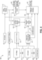
- FIG. 4 is a diagram illustrating a method for power regulation of the systems 200 and 300.
- the method 400 receives five inputs when regulating the voltage produced by systems such as the systems 200 and 300.
- the method 400 receives a DC current 401, a DC voltage 403, an AC voltage 405, an AC current 407, and a DC field current 409.
- the DC current 401 and the DC voltage 403 are the current and voltage produced by the generator system provided by the system to potentially connected loads.
- the AC voltage 405 and the AC current 407 are the voltage and current provided by the generator in the generator system before conversion from AC to DC.
- the DC field current 409 may refer to a DC field current applied to the exciter stator to drive the operation of an exciter.
- the method 400 receives the various inputs and determines how to regulate the voltage between a DC POR and an AC POR. For example, using the DC current 401, the method 400 proceeds at 411, where a load-off transient is detected. Also, using the DC voltage 403, the method 400 proceeds at 413, where DC voltage is fed back to facilitate the DC voltage regulation at the DC POR. For example, the DC voltage regulation may be provided to the GCU, which then regulates the DC voltage. The DC voltage and the outcome of the detection of the load-off transient may be provided to an AC POR or DC POR selection logic at 419.
- the method 400 receives the AC voltage at 415, where the AC voltage is feed back for regulation.
- the AC voltage 405 when the AC voltage 405 is produced by a six-phase generator, the AC voltage 405 includes six voltage measurements. Accordingly, the method 400 may also calculate a composite value for the six voltage measurements.
- the method 400 calculates a root-mean-square (RMS) value for the AC voltages 405.
- the RMS value 417 may also be provided to the AC voltage feedback 415, where the AC voltage feedback 415 uses the RMS value 417 for regulation of the AC voltage produced by the generator.
- the AC voltage feedback 415 may be additionally provided to the AC POR or DC POR selection logic 419.
- the selection logic 419 uses the DC voltage, the detected load-off transient, and the AC voltage feedback to determine whether to regulate the DC voltage or the AC voltage. For example, the selection logic may monitor the AC voltages and the DC bus voltages. When the load-off transient is detected, the selection logic 419 determines that the POR should switch from the DC voltage regulator to the AC voltage regulator. For example, the selection logic 419 determines that there is no load or a light load during a voltage buildup condition and/or steady-state operation and that the GCU should change the POR from the DC voltage regulator to AC voltage regulator. By switching the POR from the DC voltage regulator to the AC voltage regulator, a generator terminal voltage may remain stable without oscillations and maintain a desired AC line-to-line peak voltage during no-load or light-load conditions while improving voltage transients during load-on conditions.
- the method 400 proceeds at 421 with controlling an FDR and a DBR.
- the FDR and DBR may be controlled partly by DBR hardware and partly by a GCU.
- the FDR and DBR control may receive the output from the load-off transient detection and the feedback DC voltage. From the inputs, the FDR and DBR control may detect an overvoltage and turn on the DBR during a load-off transient.
- DBR hardware may include an overvoltage detection circuit during the load-off transient.
- the DBR control is taken over by the GCU.
- the GCU can produce FDR commands 423 and DBR commands 425 to control the operation of both the FDR and the DBR.
- the method 400 proceeds at 427, where a power limit, current limit, and average RMS measurements are calculated for the AC power measurements. For example, power limit, current limit, and average RMS measurements are calculated based on the AC current measurements, an RMS value for the AC current, and an RMS value for the AC voltage.
- the method 400 then proceeds at 431, where a logic selects a regulation loop. For example, using the calculated limits, the average RMS value, and the AC POR or DC POR selection, the system selects the feedback loop in either the AC POR or the DC POR to be regulated.
- the method 400 proceeds at 435, where multiple inputs are provided for use by voltage and current proportional-integral (PI) controllers.
- the voltage and current PI controllers may receive signals from the regulation loop selection logic, the FDR and DBR control, an average RMS current, and a measurement of the DC field current 409 from the exciter. Using the various inputs, the voltage and current PI controllers may provide a signal having a specific duty cycle 437 that drives the rotation of the generator. The voltage and current PI controllers can then control the voltage and current produced by the generator.
- PI proportional-integral
- FIG. 5 is a flowchart diagram of a method 500 for activating either DC voltage regulation or AC voltage regulation for power produced by a generator.
- Method 500 proceeds at 501, where operating conditions of a power generator having an AC generator and a DC converter are monitored.
- the method 500 proceeds at 503, it is determined whether the power generator is regularly operating. As described above, the power generator is regularly operating when providing DC power to a load as compared to light-load or no-load operation (or transitions between operative states).
- the method 500 proceeds at 505, where DC voltage regulation is activated.
- the method 500 proceeds at 507, where AC voltage regulation is activated. Additionally, after activating either the DC voltage regulation or the AC voltage regulation, the method 500 returns to 501 to continue monitoring operating conditions.
Landscapes
- Engineering & Computer Science (AREA)
- Power Engineering (AREA)
- Control Of Eletrric Generators (AREA)
Claims (9)
- System (200), umfassend:einen Generator (201), der dazu konfiguriert ist, Wechselstrom-, AC-, Spannung zu generieren;einen Leistungswandler (203), der dazu konfiguriert ist AC-Spannung in geregelte Gleichstrom-, DC-, Spannung zu wandeln; undeinen Spannungsregler (205), der dazu konfiguriert ist, als eine Generatorsteuereinheit für den Generator (201) zu fungieren, der Spannungsregler (205) umfassend:einen AC-Spannungsregler (351), der dazu konfiguriert ist, die AC-Spannung auf Basis einer AC-Ausgabe des Generators (201) zu regeln;einen DC-Spannungsregler (353), der dazu konfiguriert ist, die DC-Spannung auf Basis einer DC-Ausgabe des Leistungswandlers (203) zu regeln; undeinen Regler-Wahlschalter (223), der dazu konfiguriert ist, den DC-Spannungsregler während des regulären Betriebs, in welchem die DC-Spannung für eine Last (213) bereitgestellt wird, auszuwählen, und den AC-Spannungsregler (351) auszuwählen, wenn mindestens eines aus einem Strom von dem Leistungswandler (203) und einer Spannung von dem Leistungswandler (203) mindestens eines aus einem lastfreien Zustand, einem Leichtlastzustand und einem Übergang anzeigt.
- System (200) nach Anspruch 1, wobei der Regler-Wahlschalter (223) dazu konfiguriert ist, den AC-Spannungsregler (351) auf Basis eines detektierten lastfreien Zustands auszuwählen, wobei der Regler-Wahlschalter (223) dazu konfiguriert ist, den lastfreien Zustand auf Basis der Überwachung des Stroms von dem Leistungswandler (203) zu detektieren, wobei der Spannungsregler (205) dazu konfiguriert ist, die AC-Spannungen des Generators auf eine definierte Referenzspannung während eines Übergangs von einem Lastzustand zu mindestens einem aus einem lastfreien Zustand und einem Leichtlastzustand zu regeln.
- System (200) nach Anspruch 1, wobei der Spannungsregler (205) einen Feldentladewiderstand (FDR) (221) beinhaltet und dazu konfiguriert ist, eine Steuerung eines dynamischen Bremswiderstands (DBR) (216) bereitzustellen, wobei ein Betrieb des DBR (216) zusätzlich durch DBR-Hardware (218) gesteuert wird und die DBR-Hardware (218) zunächst den Betrieb des DBR (217) bei Detektieren eines Entlastungsübergangs steuert, wobei die Steuerung des DBR (217) von der DBR-Hardware (218) auf den Spannungsregler (205) übergeht.
- System (200) nach Anspruch 1, ferner umfassend einen Hochspannungs-DC-Bus (212), wobei der Hochspannungs-DC-Bus (212) dazu konfiguriert ist, die DC-Spannung zur Verwendung durch eine oder mehrere Lasten (213) bereitzustellen.
- System (200) nach Anspruch 1, wobei der Spannungsregler (205) eine Generatorsteuereinheit (325) ist.
- Verfahren, umfassend:Überwachen von Betriebszuständen eines Systems (200), das einen Generator (201), der AC-Spannung generiert, und einen Leistungswandler (203), der AC-Spannung in geregelte DC-Spannung wandelt, aufweist;Ermitteln auf Basis eines Stroms des DC-Busses (212) und der DC-Spannung, ob der Leistungsgenerator (200) regulär in Betrieb ist, wobei der Leistungsgenerator (200) regulär in Betrieb ist, wenn er DC-Spannung für eine Last (213) bereitstellt;im Falle des Ermittelns, dass der Leistungsgenerator (200) regulär in Betrieb ist, Auswählen einer DC-Spannungsregelung, um die DC-Spannung auf Basis einer DC-Ausgabe des Leistungswandlers (203) zu regeln;im Falle des Ermittelns, dass der Leistungsgenerator (200) nicht regulär in Betrieb ist, durch Identifizieren auf Basis mindestens eines aus einem Strom von dem Leistungswandler (203) und einer Spannung von dem Leistungswandler (203), von mindestens einem aus einem lastfreien Zustand, einem Leichtlastzustand und einem Übergang,Auswählen einer AC-Spannungsregelung, um die AC-Spannung auf Basis einer AC-Ausgabe des Generators (201) zu regeln; undSteuern des Betriebs des Generators auf Basis der ausgewählten Spannungsregelung.
- Verfahren nach Anspruch 6, wobei das Identifizieren des lastfreien Zustands auf Basis des Überwachens des Stroms des DC-Busses (212) erfolgt, wobei die AC-Spannungsregelung den Wert der AC-Spannung auf eine definierte Referenzspannung während eines Übergangs von einem Lastzustand in den lastfreien Zustand regelt.
- Verfahren nach Anspruch 6, ferner umfassend das Steuern des Betriebs eines Feldentladewiderstands (FDR) (221) und eines dynamischen Bremswiderstands (DBR) (216).
- Verfahren nach Anspruch 6, wobei eine Generatorsteuereinheit (325) ermittelt, ob der Leistungsgenerator (200) regulär in Betrieb ist.
Applications Claiming Priority (2)
| Application Number | Priority Date | Filing Date | Title |
|---|---|---|---|
| IN202111048163 | 2021-10-22 | ||
| US17/586,512 US11770084B2 (en) | 2021-10-22 | 2022-01-27 | Voltage regulation of high voltage direct current systems |
Publications (2)
| Publication Number | Publication Date |
|---|---|
| EP4170894A1 EP4170894A1 (de) | 2023-04-26 |
| EP4170894B1 true EP4170894B1 (de) | 2024-06-12 |
Family
ID=83902948
Family Applications (1)
| Application Number | Title | Priority Date | Filing Date |
|---|---|---|---|
| EP22202992.8A Active EP4170894B1 (de) | 2021-10-22 | 2022-10-21 | Spannungsregelung von hochspannungsgleichstromsystemen |
Country Status (1)
| Country | Link |
|---|---|
| EP (1) | EP4170894B1 (de) |
Family Cites Families (4)
| Publication number | Priority date | Publication date | Assignee | Title |
|---|---|---|---|---|
| US7508086B2 (en) * | 2006-03-24 | 2009-03-24 | General Electric Company | Aircraft engine starter/generator and controller |
| US8358111B2 (en) * | 2009-12-03 | 2013-01-22 | Hamilton Sundstrand Corporation | Architecture for dual source electric power generating system |
| US8699188B2 (en) * | 2010-10-27 | 2014-04-15 | Hamilton Sundstrand Corporation | Shunt regulator for overvoltage protection at transformer rectifier unit of electrical generating system |
| US11671038B2 (en) * | 2019-08-09 | 2023-06-06 | Hamilton Sundstrand Corporation | Control of a wound field synchronous generator for transient load response |
-
2022
- 2022-10-21 EP EP22202992.8A patent/EP4170894B1/de active Active
Also Published As
| Publication number | Publication date |
|---|---|
| EP4170894A1 (de) | 2023-04-26 |
Similar Documents
| Publication | Publication Date | Title |
|---|---|---|
| EP2137808B1 (de) | Dc-spannungsregler | |
| US8008885B2 (en) | Power converters | |
| EP2068423B1 (de) | Wechselstromerzeugungssystem | |
| US9673743B1 (en) | Efficient motor control | |
| JP3540152B2 (ja) | エンジン駆動発電機 | |
| CN108603916B (zh) | 用于识别发电机单元中的故障的方法 | |
| EP3644485B1 (de) | Steuerung eines elektrischen stromversorgungssystems mit reaktion auf die erfassung eines erdschlusses | |
| US9270219B2 (en) | Voltage-controlled DC link for variable frequency generator excitation | |
| JP2004532595A (ja) | 風力タービンの操作方法 | |
| US9660563B2 (en) | High voltage direct current system with improved generator excitation | |
| EP3518417A1 (de) | Echtzeiterfassung von motorfehlern in dreiphasigen sinusförmig angetriebenen motoren | |
| Rahnama et al. | Rotary diode failure detection in brushless exciter system of power plant synchronous generator | |
| US11770084B2 (en) | Voltage regulation of high voltage direct current systems | |
| EP4170894B1 (de) | Spannungsregelung von hochspannungsgleichstromsystemen | |
| CN106685289B (zh) | 动态限制设备以及实施这种设备的动态限制方法 | |
| US11894672B2 (en) | Wind turbine generator fault protection system | |
| EP4131771A1 (de) | Antriebsvorrichtung | |
| CN107517026B (zh) | 同步整流发电机及其保护方法 | |
| JP2020088926A (ja) | 電力変換装置、電力変換装置の制御方法 | |
| KR101372930B1 (ko) | 풍력 발전 시스템의 전력 변환 장치의 초기 충전 방법 | |
| TW201826685A (zh) | 有效的發動機控制方法及系統 | |
| JP6441880B2 (ja) | インバータ | |
| El Khil et al. | Sensorless field oriented control of doubly fed induction speed drive | |
| US11695349B2 (en) | Method for controlling a power converter | |
| Koczara et al. | Synchrogenverter-hybrid generation system |
Legal Events
| Date | Code | Title | Description |
|---|---|---|---|
| PUAI | Public reference made under article 153(3) epc to a published international application that has entered the european phase |
Free format text: ORIGINAL CODE: 0009012 |
|
| STAA | Information on the status of an ep patent application or granted ep patent |
Free format text: STATUS: THE APPLICATION HAS BEEN PUBLISHED |
|
| AK | Designated contracting states |
Kind code of ref document: A1 Designated state(s): AL AT BE BG CH CY CZ DE DK EE ES FI FR GB GR HR HU IE IS IT LI LT LU LV MC ME MK MT NL NO PL PT RO RS SE SI SK SM TR |
|
| P01 | Opt-out of the competence of the unified patent court (upc) registered |
Effective date: 20230525 |
|
| STAA | Information on the status of an ep patent application or granted ep patent |
Free format text: STATUS: REQUEST FOR EXAMINATION WAS MADE |
|
| 17P | Request for examination filed |
Effective date: 20231024 |
|
| RBV | Designated contracting states (corrected) |
Designated state(s): AL AT BE BG CH CY CZ DE DK EE ES FI FR GB GR HR HU IE IS IT LI LT LU LV MC ME MK MT NL NO PL PT RO RS SE SI SK SM TR |
|
| GRAP | Despatch of communication of intention to grant a patent |
Free format text: ORIGINAL CODE: EPIDOSNIGR1 |
|
| STAA | Information on the status of an ep patent application or granted ep patent |
Free format text: STATUS: GRANT OF PATENT IS INTENDED |
|
| RIC1 | Information provided on ipc code assigned before grant |
Ipc: H02P 9/14 20060101ALI20231215BHEP Ipc: H02K 19/38 20060101ALI20231215BHEP Ipc: H02K 7/18 20060101ALI20231215BHEP Ipc: H02P 9/10 20060101AFI20231215BHEP |
|
| INTG | Intention to grant announced |
Effective date: 20240118 |
|
| GRAS | Grant fee paid |
Free format text: ORIGINAL CODE: EPIDOSNIGR3 |
|
| GRAA | (expected) grant |
Free format text: ORIGINAL CODE: 0009210 |
|
| STAA | Information on the status of an ep patent application or granted ep patent |
Free format text: STATUS: THE PATENT HAS BEEN GRANTED |
|
| AK | Designated contracting states |
Kind code of ref document: B1 Designated state(s): AL AT BE BG CH CY CZ DE DK EE ES FI FR GB GR HR HU IE IS IT LI LT LU LV MC ME MK MT NL NO PL PT RO RS SE SI SK SM TR |
|
| REG | Reference to a national code |
Ref country code: GB Ref legal event code: FG4D |
|
| REG | Reference to a national code |
Ref country code: CH Ref legal event code: EP |
|
| REG | Reference to a national code |
Ref country code: IE Ref legal event code: FG4D |
|
| REG | Reference to a national code |
Ref country code: DE Ref legal event code: R096 Ref document number: 602022003930 Country of ref document: DE |
|
| PG25 | Lapsed in a contracting state [announced via postgrant information from national office to epo] |
Ref country code: BG Free format text: LAPSE BECAUSE OF FAILURE TO SUBMIT A TRANSLATION OF THE DESCRIPTION OR TO PAY THE FEE WITHIN THE PRESCRIBED TIME-LIMIT Effective date: 20240612 |
|
| PG25 | Lapsed in a contracting state [announced via postgrant information from national office to epo] |
Ref country code: FI Free format text: LAPSE BECAUSE OF FAILURE TO SUBMIT A TRANSLATION OF THE DESCRIPTION OR TO PAY THE FEE WITHIN THE PRESCRIBED TIME-LIMIT Effective date: 20240612 Ref country code: HR Free format text: LAPSE BECAUSE OF FAILURE TO SUBMIT A TRANSLATION OF THE DESCRIPTION OR TO PAY THE FEE WITHIN THE PRESCRIBED TIME-LIMIT Effective date: 20240612 |
|
| REG | Reference to a national code |
Ref country code: LT Ref legal event code: MG9D |
|
| PG25 | Lapsed in a contracting state [announced via postgrant information from national office to epo] |
Ref country code: GR Free format text: LAPSE BECAUSE OF FAILURE TO SUBMIT A TRANSLATION OF THE DESCRIPTION OR TO PAY THE FEE WITHIN THE PRESCRIBED TIME-LIMIT Effective date: 20240913 |
|
| REG | Reference to a national code |
Ref country code: NL Ref legal event code: MP Effective date: 20240612 |
|
| PG25 | Lapsed in a contracting state [announced via postgrant information from national office to epo] |
Ref country code: ES Free format text: LAPSE BECAUSE OF FAILURE TO SUBMIT A TRANSLATION OF THE DESCRIPTION OR TO PAY THE FEE WITHIN THE PRESCRIBED TIME-LIMIT Effective date: 20240612 |
|
| PG25 | Lapsed in a contracting state [announced via postgrant information from national office to epo] |
Ref country code: LV Free format text: LAPSE BECAUSE OF FAILURE TO SUBMIT A TRANSLATION OF THE DESCRIPTION OR TO PAY THE FEE WITHIN THE PRESCRIBED TIME-LIMIT Effective date: 20240612 |
|
| PG25 | Lapsed in a contracting state [announced via postgrant information from national office to epo] |
Ref country code: NO Free format text: LAPSE BECAUSE OF FAILURE TO SUBMIT A TRANSLATION OF THE DESCRIPTION OR TO PAY THE FEE WITHIN THE PRESCRIBED TIME-LIMIT Effective date: 20240912 Ref country code: LV Free format text: LAPSE BECAUSE OF FAILURE TO SUBMIT A TRANSLATION OF THE DESCRIPTION OR TO PAY THE FEE WITHIN THE PRESCRIBED TIME-LIMIT Effective date: 20240612 Ref country code: HR Free format text: LAPSE BECAUSE OF FAILURE TO SUBMIT A TRANSLATION OF THE DESCRIPTION OR TO PAY THE FEE WITHIN THE PRESCRIBED TIME-LIMIT Effective date: 20240612 Ref country code: GR Free format text: LAPSE BECAUSE OF FAILURE TO SUBMIT A TRANSLATION OF THE DESCRIPTION OR TO PAY THE FEE WITHIN THE PRESCRIBED TIME-LIMIT Effective date: 20240913 Ref country code: FI Free format text: LAPSE BECAUSE OF FAILURE TO SUBMIT A TRANSLATION OF THE DESCRIPTION OR TO PAY THE FEE WITHIN THE PRESCRIBED TIME-LIMIT Effective date: 20240612 Ref country code: ES Free format text: LAPSE BECAUSE OF FAILURE TO SUBMIT A TRANSLATION OF THE DESCRIPTION OR TO PAY THE FEE WITHIN THE PRESCRIBED TIME-LIMIT Effective date: 20240612 Ref country code: BG Free format text: LAPSE BECAUSE OF FAILURE TO SUBMIT A TRANSLATION OF THE DESCRIPTION OR TO PAY THE FEE WITHIN THE PRESCRIBED TIME-LIMIT Effective date: 20240612 Ref country code: RS Free format text: LAPSE BECAUSE OF FAILURE TO SUBMIT A TRANSLATION OF THE DESCRIPTION OR TO PAY THE FEE WITHIN THE PRESCRIBED TIME-LIMIT Effective date: 20240912 |
|
| PG25 | Lapsed in a contracting state [announced via postgrant information from national office to epo] |
Ref country code: NL Free format text: LAPSE BECAUSE OF FAILURE TO SUBMIT A TRANSLATION OF THE DESCRIPTION OR TO PAY THE FEE WITHIN THE PRESCRIBED TIME-LIMIT Effective date: 20240612 |
|
| REG | Reference to a national code |
Ref country code: AT Ref legal event code: MK05 Ref document number: 1695066 Country of ref document: AT Kind code of ref document: T Effective date: 20240612 |
|
| PG25 | Lapsed in a contracting state [announced via postgrant information from national office to epo] |
Ref country code: NL Free format text: LAPSE BECAUSE OF FAILURE TO SUBMIT A TRANSLATION OF THE DESCRIPTION OR TO PAY THE FEE WITHIN THE PRESCRIBED TIME-LIMIT Effective date: 20240612 |
|
| PG25 | Lapsed in a contracting state [announced via postgrant information from national office to epo] |
Ref country code: PT Free format text: LAPSE BECAUSE OF FAILURE TO SUBMIT A TRANSLATION OF THE DESCRIPTION OR TO PAY THE FEE WITHIN THE PRESCRIBED TIME-LIMIT Effective date: 20241014 |
|
| PG25 | Lapsed in a contracting state [announced via postgrant information from national office to epo] |
Ref country code: PT Free format text: LAPSE BECAUSE OF FAILURE TO SUBMIT A TRANSLATION OF THE DESCRIPTION OR TO PAY THE FEE WITHIN THE PRESCRIBED TIME-LIMIT Effective date: 20241014 |
|
| PG25 | Lapsed in a contracting state [announced via postgrant information from national office to epo] |
Ref country code: PL Free format text: LAPSE BECAUSE OF FAILURE TO SUBMIT A TRANSLATION OF THE DESCRIPTION OR TO PAY THE FEE WITHIN THE PRESCRIBED TIME-LIMIT Effective date: 20240612 |
|
| PG25 | Lapsed in a contracting state [announced via postgrant information from national office to epo] |
Ref country code: EE Free format text: LAPSE BECAUSE OF FAILURE TO SUBMIT A TRANSLATION OF THE DESCRIPTION OR TO PAY THE FEE WITHIN THE PRESCRIBED TIME-LIMIT Effective date: 20240612 |
|
| PG25 | Lapsed in a contracting state [announced via postgrant information from national office to epo] |
Ref country code: IS Free format text: LAPSE BECAUSE OF FAILURE TO SUBMIT A TRANSLATION OF THE DESCRIPTION OR TO PAY THE FEE WITHIN THE PRESCRIBED TIME-LIMIT Effective date: 20241012 Ref country code: AT Free format text: LAPSE BECAUSE OF FAILURE TO SUBMIT A TRANSLATION OF THE DESCRIPTION OR TO PAY THE FEE WITHIN THE PRESCRIBED TIME-LIMIT Effective date: 20240612 |
|
| PG25 | Lapsed in a contracting state [announced via postgrant information from national office to epo] |
Ref country code: CZ Free format text: LAPSE BECAUSE OF FAILURE TO SUBMIT A TRANSLATION OF THE DESCRIPTION OR TO PAY THE FEE WITHIN THE PRESCRIBED TIME-LIMIT Effective date: 20240612 |
|
| PG25 | Lapsed in a contracting state [announced via postgrant information from national office to epo] |
Ref country code: SK Free format text: LAPSE BECAUSE OF FAILURE TO SUBMIT A TRANSLATION OF THE DESCRIPTION OR TO PAY THE FEE WITHIN THE PRESCRIBED TIME-LIMIT Effective date: 20240612 Ref country code: RO Free format text: LAPSE BECAUSE OF FAILURE TO SUBMIT A TRANSLATION OF THE DESCRIPTION OR TO PAY THE FEE WITHIN THE PRESCRIBED TIME-LIMIT Effective date: 20240612 |
|
| PG25 | Lapsed in a contracting state [announced via postgrant information from national office to epo] |
Ref country code: SM Free format text: LAPSE BECAUSE OF FAILURE TO SUBMIT A TRANSLATION OF THE DESCRIPTION OR TO PAY THE FEE WITHIN THE PRESCRIBED TIME-LIMIT Effective date: 20240612 |
|
| PG25 | Lapsed in a contracting state [announced via postgrant information from national office to epo] |
Ref country code: SM Free format text: LAPSE BECAUSE OF FAILURE TO SUBMIT A TRANSLATION OF THE DESCRIPTION OR TO PAY THE FEE WITHIN THE PRESCRIBED TIME-LIMIT Effective date: 20240612 Ref country code: SK Free format text: LAPSE BECAUSE OF FAILURE TO SUBMIT A TRANSLATION OF THE DESCRIPTION OR TO PAY THE FEE WITHIN THE PRESCRIBED TIME-LIMIT Effective date: 20240612 Ref country code: RO Free format text: LAPSE BECAUSE OF FAILURE TO SUBMIT A TRANSLATION OF THE DESCRIPTION OR TO PAY THE FEE WITHIN THE PRESCRIBED TIME-LIMIT Effective date: 20240612 Ref country code: PL Free format text: LAPSE BECAUSE OF FAILURE TO SUBMIT A TRANSLATION OF THE DESCRIPTION OR TO PAY THE FEE WITHIN THE PRESCRIBED TIME-LIMIT Effective date: 20240612 Ref country code: IS Free format text: LAPSE BECAUSE OF FAILURE TO SUBMIT A TRANSLATION OF THE DESCRIPTION OR TO PAY THE FEE WITHIN THE PRESCRIBED TIME-LIMIT Effective date: 20241012 Ref country code: EE Free format text: LAPSE BECAUSE OF FAILURE TO SUBMIT A TRANSLATION OF THE DESCRIPTION OR TO PAY THE FEE WITHIN THE PRESCRIBED TIME-LIMIT Effective date: 20240612 Ref country code: CZ Free format text: LAPSE BECAUSE OF FAILURE TO SUBMIT A TRANSLATION OF THE DESCRIPTION OR TO PAY THE FEE WITHIN THE PRESCRIBED TIME-LIMIT Effective date: 20240612 Ref country code: AT Free format text: LAPSE BECAUSE OF FAILURE TO SUBMIT A TRANSLATION OF THE DESCRIPTION OR TO PAY THE FEE WITHIN THE PRESCRIBED TIME-LIMIT Effective date: 20240612 |
|
| PG25 | Lapsed in a contracting state [announced via postgrant information from national office to epo] |
Ref country code: IT Free format text: LAPSE BECAUSE OF FAILURE TO SUBMIT A TRANSLATION OF THE DESCRIPTION OR TO PAY THE FEE WITHIN THE PRESCRIBED TIME-LIMIT Effective date: 20240612 |
|
| REG | Reference to a national code |
Ref country code: DE Ref legal event code: R097 Ref document number: 602022003930 Country of ref document: DE |
|
| PG25 | Lapsed in a contracting state [announced via postgrant information from national office to epo] |
Ref country code: DK Free format text: LAPSE BECAUSE OF FAILURE TO SUBMIT A TRANSLATION OF THE DESCRIPTION OR TO PAY THE FEE WITHIN THE PRESCRIBED TIME-LIMIT Effective date: 20240612 |
|
| PLBE | No opposition filed within time limit |
Free format text: ORIGINAL CODE: 0009261 |
|
| STAA | Information on the status of an ep patent application or granted ep patent |
Free format text: STATUS: NO OPPOSITION FILED WITHIN TIME LIMIT |
|
| REG | Reference to a national code |
Ref country code: DE Ref legal event code: R119 Ref document number: 602022003930 Country of ref document: DE |
|
| 26N | No opposition filed |
Effective date: 20250313 |
|
| PG25 | Lapsed in a contracting state [announced via postgrant information from national office to epo] |
Ref country code: MC Free format text: LAPSE BECAUSE OF FAILURE TO SUBMIT A TRANSLATION OF THE DESCRIPTION OR TO PAY THE FEE WITHIN THE PRESCRIBED TIME-LIMIT Effective date: 20240612 |
|
| PG25 | Lapsed in a contracting state [announced via postgrant information from national office to epo] |
Ref country code: DE Free format text: LAPSE BECAUSE OF NON-PAYMENT OF DUE FEES Effective date: 20250501 |
|
| PG25 | Lapsed in a contracting state [announced via postgrant information from national office to epo] |
Ref country code: LU Free format text: LAPSE BECAUSE OF NON-PAYMENT OF DUE FEES Effective date: 20241021 Ref country code: BE Free format text: LAPSE BECAUSE OF NON-PAYMENT OF DUE FEES Effective date: 20241031 |
|
| REG | Reference to a national code |
Ref country code: BE Ref legal event code: MM Effective date: 20241031 |
|
| PG25 | Lapsed in a contracting state [announced via postgrant information from national office to epo] |
Ref country code: SE Free format text: LAPSE BECAUSE OF FAILURE TO SUBMIT A TRANSLATION OF THE DESCRIPTION OR TO PAY THE FEE WITHIN THE PRESCRIBED TIME-LIMIT Effective date: 20240612 |
|
| PG25 | Lapsed in a contracting state [announced via postgrant information from national office to epo] |
Ref country code: IE Free format text: LAPSE BECAUSE OF NON-PAYMENT OF DUE FEES Effective date: 20241021 |
|
| PGFP | Annual fee paid to national office [announced via postgrant information from national office to epo] |
Ref country code: FR Payment date: 20251027 Year of fee payment: 4 |
|
| PG25 | Lapsed in a contracting state [announced via postgrant information from national office to epo] |
Ref country code: CY Free format text: LAPSE BECAUSE OF FAILURE TO SUBMIT A TRANSLATION OF THE DESCRIPTION OR TO PAY THE FEE WITHIN THE PRESCRIBED TIME-LIMIT; INVALID AB INITIO Effective date: 20221021 |
|
| PG25 | Lapsed in a contracting state [announced via postgrant information from national office to epo] |
Ref country code: HU Free format text: LAPSE BECAUSE OF FAILURE TO SUBMIT A TRANSLATION OF THE DESCRIPTION OR TO PAY THE FEE WITHIN THE PRESCRIBED TIME-LIMIT; INVALID AB INITIO Effective date: 20221021 |