EP4170415A1 - Smart glasses, wireless earphones, wearable device assembly and control method therefor - Google Patents
Smart glasses, wireless earphones, wearable device assembly and control method therefor Download PDFInfo
- Publication number
- EP4170415A1 EP4170415A1 EP21826883.7A EP21826883A EP4170415A1 EP 4170415 A1 EP4170415 A1 EP 4170415A1 EP 21826883 A EP21826883 A EP 21826883A EP 4170415 A1 EP4170415 A1 EP 4170415A1
- Authority
- EP
- European Patent Office
- Prior art keywords
- electrical connection
- glasses
- glasses leg
- connection part
- leg
- Prior art date
- Legal status (The legal status is an assumption and is not a legal conclusion. Google has not performed a legal analysis and makes no representation as to the accuracy of the status listed.)
- Pending
Links
Images



Classifications
-
- G—PHYSICS
- G02—OPTICS
- G02C—SPECTACLES; SUNGLASSES OR GOGGLES INSOFAR AS THEY HAVE THE SAME FEATURES AS SPECTACLES; CONTACT LENSES
- G02C11/00—Non-optical adjuncts; Attachment thereof
- G02C11/06—Hearing aids
-
- G—PHYSICS
- G02—OPTICS
- G02B—OPTICAL ELEMENTS, SYSTEMS OR APPARATUS
- G02B27/00—Optical systems or apparatus not provided for by any of the groups G02B1/00 - G02B26/00, G02B30/00
- G02B27/01—Head-up displays
- G02B27/017—Head mounted
- G02B27/0176—Head mounted characterised by mechanical features
-
- G—PHYSICS
- G02—OPTICS
- G02C—SPECTACLES; SUNGLASSES OR GOGGLES INSOFAR AS THEY HAVE THE SAME FEATURES AS SPECTACLES; CONTACT LENSES
- G02C11/00—Non-optical adjuncts; Attachment thereof
- G02C11/10—Electronic devices other than hearing aids
-
- G—PHYSICS
- G02—OPTICS
- G02C—SPECTACLES; SUNGLASSES OR GOGGLES INSOFAR AS THEY HAVE THE SAME FEATURES AS SPECTACLES; CONTACT LENSES
- G02C5/00—Constructions of non-optical parts
- G02C5/14—Side-members
- G02C5/143—Side-members having special ear pieces
-
- G—PHYSICS
- G02—OPTICS
- G02C—SPECTACLES; SUNGLASSES OR GOGGLES INSOFAR AS THEY HAVE THE SAME FEATURES AS SPECTACLES; CONTACT LENSES
- G02C5/00—Constructions of non-optical parts
- G02C5/22—Hinges
- G02C5/229—Oblique hinge axis
-
- H—ELECTRICITY
- H04—ELECTRIC COMMUNICATION TECHNIQUE
- H04R—LOUDSPEAKERS, MICROPHONES, GRAMOPHONE PICK-UPS OR LIKE ACOUSTIC ELECTROMECHANICAL TRANSDUCERS; ELECTRIC HEARING AIDS; PUBLIC ADDRESS SYSTEMS
- H04R1/00—Details of transducers, loudspeakers or microphones
- H04R1/10—Earpieces; Attachments therefor ; Earphones; Monophonic headphones
-
- H—ELECTRICITY
- H04—ELECTRIC COMMUNICATION TECHNIQUE
- H04R—LOUDSPEAKERS, MICROPHONES, GRAMOPHONE PICK-UPS OR LIKE ACOUSTIC ELECTROMECHANICAL TRANSDUCERS; ELECTRIC HEARING AIDS; PUBLIC ADDRESS SYSTEMS
- H04R1/00—Details of transducers, loudspeakers or microphones
- H04R1/10—Earpieces; Attachments therefor ; Earphones; Monophonic headphones
- H04R1/1025—Accumulators specially adapted for earpieces; Arrangements specially adapted for charging thereof
-
- H—ELECTRICITY
- H04—ELECTRIC COMMUNICATION TECHNIQUE
- H04R—LOUDSPEAKERS, MICROPHONES, GRAMOPHONE PICK-UPS OR LIKE ACOUSTIC ELECTROMECHANICAL TRANSDUCERS; ELECTRIC HEARING AIDS; PUBLIC ADDRESS SYSTEMS
- H04R1/00—Details of transducers, loudspeakers or microphones
- H04R1/10—Earpieces; Attachments therefor ; Earphones; Monophonic headphones
- H04R1/1041—Mechanical or electronic switches, or control elements
-
- H—ELECTRICITY
- H04—ELECTRIC COMMUNICATION TECHNIQUE
- H04R—LOUDSPEAKERS, MICROPHONES, GRAMOPHONE PICK-UPS OR LIKE ACOUSTIC ELECTROMECHANICAL TRANSDUCERS; ELECTRIC HEARING AIDS; PUBLIC ADDRESS SYSTEMS
- H04R1/00—Details of transducers, loudspeakers or microphones
- H04R1/10—Earpieces; Attachments therefor ; Earphones; Monophonic headphones
- H04R1/1058—Manufacture or assembly
- H04R1/1066—Constructional aspects of the interconnection between earpiece and earpiece support
-
- G—PHYSICS
- G02—OPTICS
- G02B—OPTICAL ELEMENTS, SYSTEMS OR APPARATUS
- G02B27/00—Optical systems or apparatus not provided for by any of the groups G02B1/00 - G02B26/00, G02B30/00
- G02B27/01—Head-up displays
- G02B27/017—Head mounted
- G02B2027/0178—Eyeglass type
-
- G—PHYSICS
- G02—OPTICS
- G02C—SPECTACLES; SUNGLASSES OR GOGGLES INSOFAR AS THEY HAVE THE SAME FEATURES AS SPECTACLES; CONTACT LENSES
- G02C2200/00—Generic mechanical aspects applicable to one or more of the groups G02C1/00 - G02C5/00 and G02C9/00 - G02C13/00 and their subgroups
- G02C2200/02—Magnetic means
-
- H—ELECTRICITY
- H04—ELECTRIC COMMUNICATION TECHNIQUE
- H04R—LOUDSPEAKERS, MICROPHONES, GRAMOPHONE PICK-UPS OR LIKE ACOUSTIC ELECTROMECHANICAL TRANSDUCERS; ELECTRIC HEARING AIDS; PUBLIC ADDRESS SYSTEMS
- H04R1/00—Details of transducers, loudspeakers or microphones
- H04R1/10—Earpieces; Attachments therefor ; Earphones; Monophonic headphones
- H04R1/1016—Earpieces of the intra-aural type
-
- H—ELECTRICITY
- H04—ELECTRIC COMMUNICATION TECHNIQUE
- H04R—LOUDSPEAKERS, MICROPHONES, GRAMOPHONE PICK-UPS OR LIKE ACOUSTIC ELECTROMECHANICAL TRANSDUCERS; ELECTRIC HEARING AIDS; PUBLIC ADDRESS SYSTEMS
- H04R2201/00—Details of transducers, loudspeakers or microphones covered by H04R1/00 but not provided for in any of its subgroups
- H04R2201/10—Details of earpieces, attachments therefor, earphones or monophonic headphones covered by H04R1/10 but not provided for in any of its subgroups
-
- H—ELECTRICITY
- H04—ELECTRIC COMMUNICATION TECHNIQUE
- H04R—LOUDSPEAKERS, MICROPHONES, GRAMOPHONE PICK-UPS OR LIKE ACOUSTIC ELECTROMECHANICAL TRANSDUCERS; ELECTRIC HEARING AIDS; PUBLIC ADDRESS SYSTEMS
- H04R5/00—Stereophonic arrangements
- H04R5/033—Headphones for stereophonic communication
Definitions
- an embodiment of this application discloses a control apparatus for a wearable device assembly, where the wearable device assembly is the foregoing wearable device assembly, and the control apparatus includes:
- the user can continue to use the smart glasses and the wireless earphone, so that it can be prevented that the wireless earphone is required to be put into an earphone box when being charged and the wireless earphone cannot be worn when being charged, and then it can be prevented that the user has no way of using the wireless earphone. Accordingly, use experience can be improved for the user.
- the magnetic component refers to a component with magnetism, for example, the magnetic component may be an electromagnet, a permanent magnet, or the like
- the magnetically attractable component refers to a component that can be magnetically attracted, for example, the magnetically attractable component may be an electromagnet, a permanent magnet, an iron component, or the like.
- the earphone body 220 is located between the user and the glasses leg 120, and the second electrical connection part 210 is located on a side of the earphone body 220 facing away from the user, so that the first electrical connection part 121 is just opposite to the second electrical connection part 210, which can help the user operate the glasses leg 120. Therefore, electrical connection between the first electrical connection part 121 and the second electrical connection part 210 can be implemented, thereby improving operation convenience for the smart glasses 100.
- control switch can be controlled manually by the user or by control software in the smart glasses 100.
- the wireless earphone 200 is provided with a second electrical connection part 210.
- the glasses leg 120 In a case that the glasses leg 120 is located at the first position, the glasses leg 120 is separated from the wireless earphone 200.
- the wireless earphone 200 In a case that the glasses leg 120 is located at the second position, the wireless earphone 200 is connected to the glasses leg 120, and the first electrical connection part 121 is electrically connected to the second electrical connection part 210.
Landscapes
- Physics & Mathematics (AREA)
- Health & Medical Sciences (AREA)
- Acoustics & Sound (AREA)
- Engineering & Computer Science (AREA)
- Optics & Photonics (AREA)
- General Physics & Mathematics (AREA)
- Signal Processing (AREA)
- Ophthalmology & Optometry (AREA)
- Otolaryngology (AREA)
- General Health & Medical Sciences (AREA)
- Manufacturing & Machinery (AREA)
- Telephone Set Structure (AREA)
- Eyeglasses (AREA)
Abstract
Description
- The present invention claims priority to
Chinese Patent Application No. 202010571326.5, filed with the China National Intellectual Property Administration on June 19, 2020 - This application relates to the technical field of smart wearable devices, and in particular to a pair of smart glasses, a pair of wireless earphones, a wearable device assembly, and a control method therefor.
- In today's society, various electronic products emerge in endlessly. To make users enjoy convenience brought by electronic products without disturbing surrounding environments, a function of earphones cannot be ignored. With the rapid development of science and technology in recent years, wireless earphones gradually appear in people's life. Wireless earphones are favored by users because they are easy to carry. Such earphones can avoid various inconveniences in use of traditional wired earphones.
- Nowadays, an increasing number of functions are integrated on the wireless earphones, which leads to greater power consumption of the wireless earphones. Moreover, due to small sizes of the wireless earphones, sizes of batteries set on the wireless earphones are small, resulting in a small capacity of the batteries, so that a battery life of the wireless earphones is insufficient. Therefore, to make the wireless earphones have a long battery life, existing wireless earphones are generally required to be equipped with an earphone box provided with a battery, so that the earphone box can charge the wireless earphones. However, the wireless earphones need to be put in the earphone box when being charged. In this case, a user cannot wear the wireless earphones. Accordingly, the user has no way of using the wireless earphones, which affects use experience of the user.
- This application discloses a pair of smart glasses, a pair of wireless earphones, a wearable device assembly, and a control method therefor, which can resolve a problem that a user has no way of using the wireless earphones during charging.
- To resolve the foregoing technical problem, this application is implemented as follows.
- According to a first aspect, an embodiment of this application discloses a pair of smart glasses, where the smart glasses can be electrically connected to a pair of wireless earphones, and one wireless earphone is provided with a second electrical connection part, the smart glasses includes a main body and a pair of glasses legs, where one glasses leg is rotatably connected to the main body, and the glasses leg can be rotatably switched between a first position and a second position relative to the main body, the glasses leg is provided with a first electrical connection part, at least one of the glasses leg and the main body is provided with a battery module, and the first electrical connection part is electrically connected to the battery module;
in a case that the glasses leg is located at the first position, the glasses leg is separated from the wireless earphone; and in a case that the glasses leg is located at the second position, the glasses leg is connected to the wireless earphone, and the first electrical connection part is electrically connected to the second electrical connection part. - According to a second aspect, an embodiment of this application discloses a pair of wireless earphones, where the wireless earphone can be electrically connected to a pair of smart glasses, and the smart glasses includes a main body and a pair of glasses legs, where one glasses leg is connected to the main body, and the glasses leg can be rotatably switched between a first position and a second position relative to the main body, the glasses leg is provided with a first electrical connection part, at least one of the glasses leg and the main body is provided with a battery module, and the first electrical connection part is electrically connected to the battery module, and the wireless earphone is provided with a second electrical connection part;
in a case that the glasses leg is located at the first position, the glasses leg is separated from the wireless earphone; and in a case that the glasses leg is located at the second position, the wireless earphone is connected to the glasses leg, and the first electrical connection part is electrically connected to the second electrical connection part. - According to a third aspect, an embodiment of this application discloses a wearable device assembly, including the foregoing smart glasses and the foregoing wireless earphones, and the smart glasses can be electrically connected to the wireless earphones.
- According to a fourth aspect, an embodiment of this application discloses a control method for a wearable device assembly, applied to the foregoing wearable device assembly, and including:
- detecting a current position of the glasses leg, where the current position of the glasses leg includes the first position and the second position;
- controlling, in a case that the current position is the first position, the first electrical connection part to be powered off; and
- controlling, in a case that the current position is the second position, the first electrical connection part to be powered on.
- According to a fifth aspect, an embodiment of this application discloses a control apparatus for a wearable device assembly, where the wearable device assembly is the foregoing wearable device assembly, and the control apparatus includes:
- a detection module, configured to detect a current position of the glasses leg, where the current position of the glasses leg includes the first position and the second position;
- a first control module, configured to control, in a case that the current position is the first position, the first electrical connection part to be powered off, and
- a second control module, configured to control, in a case that the current position is the second position, the first electrical connection part to be powered on.
- According to a sixth aspect, an embodiment of this application discloses a wearable device assembly, including a processor, a memory, and a program or an instruction stored in the memory and capable of running on the processor, where when the program or the instruction is executed by the processor, the steps of the foregoing control method are implemented.
- According to a seventh aspect, an embodiment of this application discloses a readable storage medium, where the readable storage medium stores a program or an instruction, and the program or the instruction is executed by a processor to implement the steps of the foregoing control method.
- The technical solutions used in this application can achieve the following beneficial effects.
- In the smart glasses disclosed in this application, the glasses leg can be rotatably switched between the first position and the second position relative to the main body. In addition, in a case that the glasses leg is located at the first position, the glasses leg is separated from the wireless earphone, and in a case that the glasses leg is located at the second position, the glasses leg is connected to the wireless earphone, and the first electrical connection part is electrically connected to the second electrical connection part. The smart glasses can charge or supply power to the wireless earphone by changing a position of the glasses leg. While the wireless earphone is being charged or supplied with power in this way, the user can continue to use the smart glasses and the wireless earphone, so that it can be prevented that the wireless earphone is required to be put into an earphone box when being charged and the wireless earphone cannot be worn when being charged, and then it can be prevented that the user has no way of using the wireless earphone. Accordingly, use experience can be improved for the user.
- To describe the technical solutions in the embodiments of this application or in the background art more clearly, the drawings required for describing the embodiments or the background art are described briefly below. Obviously, other drawings can be obtained by those of ordinary skill in the art based on these drawings without creative efforts.
-
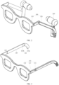
FIG. 1 is a schematic diagram of a glasses leg at a first position of smart glasses in a wearable device assembly disclosed in an embodiment of this application; -
FIG. 2 is a schematic diagram of the glasses leg at a second position of the smart glasses in the wearable device assembly disclosed in an embodiment of this application; -
FIG. 3 is a schematic diagram of the smart glasses disclosed in an embodiment of this application; -
FIG. 4 is a cross-sectional view of the glasses leg at the first position of the smart glasses disclosed in an embodiment of this application; -
FIG. 5 is a cross-sectional view of the glasses leg at the second position of the smart glasses disclosed in an embodiment of this application; -
FIG. 6 is a schematic exploded view of the smart glasses disclosed in an embodiment of this application; -
FIG. 7 is a schematic diagram of a wireless earphone disclosed in an embodiment of this application; -
FIG. 8 is a schematic diagram ofFIG. 7 at another viewing angle; -
FIG. 9 is a schematic diagram of a wearable device assembly used by a user; -
FIG. 10 is another schematic diagram of the wearable device assembly used by the user; and -
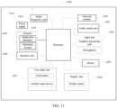
FIG. 11 is a schematic diagram of the wearable device assembly. - Reference numerals in the accompanying drawings are as follows:
- 100-Smart glasses, 110-Main body, 111-Rotation stopping part, 112-Glasses frame, 113-Connection section, 120-Glasses leg, 121-First electrical connection part, 121a-First electrical connection terminal, 121b-First connector, 122-Limiting surface, 200-Wireless earphone, 210-Second electrical connection part, 210a-Second electrical connection terminal, 210b-Second connector, 220-Earphone body, 230-Speaker;
- 1200-Wearable device assembly, 1201-Radio frequency unit, 1202-Network module, 1203-Audio output unit, 1204-Input unit, 1205-Sensor, 1206-Display unit, 1207-User input unit, 1208-Interface unit, 1209-Memory, 1210-Processor, 1211-Power supply.
- To make the objectives, technical solutions, and advantages of this application clearer, the following clearly and completely describes the technical solutions of this application with reference to the specific embodiments of this application and the corresponding accompanying drawings. Apparently, the described embodiments are merely some rather than all of the embodiments of this application. All other embodiments obtained by a person of ordinary skill in the art based on the embodiments of this application without creative efforts shall fall within the protection scope of this application.
- Terms "first" and "second" in the specification and claims of this application are used to distinguish between similar objects, and are not used to describe a specific order or sequence. It should be understood that data used in this way may be interchangeable in appropriate cases, so that the embodiments of this application can be implemented in a sequence other than those shown or described herein. In addition, objects distinguished by "first", "second", and the like usually belong to one type, and the number of the objects is not limited. For example, there may be one or more first objects. In addition, in the specification and the claims, "and/or" represents at least one of connected objects, and the character "/" generally represents an "or" relationship between associated objects.
- With reference to the following drawings, technical solutions disclosed by various embodiments of this application will be explained in detail through specific embodiments and application scenarios thereof.
- Please refer to
FIG. 1 to FIG. 10 , an embodiment of this application discloses a pair ofsmart glasses 100. The disclosedsmart glasses 100 can be electrically connected to a pair ofwireless earphones 200, onewireless earphone 200 is provided with a secondelectrical connection part 210, and a user can supply power to or charge thewireless earphone 200 through the secondelectrical connection part 210. Definitely, thewireless earphone 200 can also be in data connection with other kinds of electronic devices through the secondelectrical connection part 210. - The
smart glasses 100 include amain body 110 and a pair ofglasses legs 120, where themain body 110 is a basic member of thesmart glasses 100, and themain body 110 can provide a mounting basis for other components of thesmart glasses 100. Themain body 110 generally includes an optical module holder, the optical module holder can provide a mounting basis for an optical component of thesmart glasses 100, and the optical component may be a spectacle lens and a display screen. Theglasses legs 120 are used for wearing thesmart glasses 100. - The
smart glasses 100 generally further include a battery module, and at least one of themain body 110 and theglasses legs 120 are provided with the battery module. Definitely, themain body 110 and theglasses legs 120 may both be provided with battery modules, so that thesmart glasses 100 have a great battery capacity, and thesmart glasses 100 have a long battery life. Oneglasses leg 120 is provided with a firstelectrical connection part 121, and the firstelectrical connection part 121 is electrically connected to the battery module, so that the user can charge the battery module through the firstelectrical connection part 121. Alternatively, the battery module supplies power to or charges other kinds of electronic devices through the firstelectrical connection part 121. Definitely, thesmart glasses 100 can also be in data connection with other kinds of electronic devices through the firstelectrical connection part 121. - The
glasses leg 120 is rotatably connected to themain body 110, so that theglasses leg 120 can be rotatably switched between a first position and a second position relative to themain body 110. In a case that theglasses leg 120 is located at the first position, theglasses leg 120 is separated from thewireless earphone 200. In this case, thewireless earphone 200 works independently from thesmart glasses 100, and thewireless earphone 200 does not need to be charged or supplied with power by thesmart glasses 100, or thewireless earphone 200 does not need to be in data connection with thesmart glasses 100. In a case that theglasses leg 120 is located at the second position, theglasses leg 120 is connected to thewireless earphone 200, and the firstelectrical connection part 121 is electrically connected to the secondelectrical connection part 210. In this case, thesmart glasses 100 charge or supply power to thewireless earphone 200 through the firstelectrical connection part 121 and the secondelectrical connection part 210. Alternatively, thesmart glasses 100 are in data connection with thewireless earphone 200 through the firstelectrical connection part 121 and the secondelectrical connection part 210, so that data exchange can be implemented between thesmart glasses 100 and thewireless earphone 200. - In a specific use process of the user, when the
wireless earphone 200 needs to be supplied with power or charged, the user can manually drive theglasses leg 120 to rotate, so as to enable theglasses leg 120 to be rotated to the second position, so that thewireless earphone 200 is connected to theglasses leg 120, and the firstelectrical connection part 121 is electrically connected to the secondelectrical connection part 210. In this case, thesmart glasses 100 charge or supply power to thewireless earphone 200 through the firstelectrical connection part 121 and the secondelectrical connection part 210, and while thewireless earphone 200 is charged or supplied with power in this way, the user can continue to use thesmart glasses 100 and thewireless earphone 200. After thewireless earphone 200 is charged or when the wireless earphone does not need to be supplied with power, the user can manually drive theglasses leg 120 to rotate, to enable theglasses leg 120 to rotate from the second position to the first position, so that thewireless earphone 200 is separated from theglasses leg 120, and then thewireless earphone 200 works independently with thesmart glasses 100. It should be noted that independent working means that thewireless earphone 200 and thesmart glasses 100 work in a separate state. - In the
smart glasses 100 disclosed in this application, theglasses leg 120 can be rotatably switched between the first position and the second position relative to themain body 110. In addition, in a case that theglasses leg 120 is located at the first position, theglasses leg 120 is separated from thewireless earphone 200, and in a case that theglasses leg 120 is located at the second position, theglasses leg 120 is connected to thewireless earphone 200, and the firstelectrical connection part 121 is electrically connected to the secondelectrical connection part 210. Thesmart glasses 100 can charge or supply power to thewireless earphone 200 by changing a position of theglasses leg 120. While thewireless earphone 200 is being charged or supplied with power in this way, the user can continue to use thesmart glasses 100 and thewireless earphone 200, so that it can be prevented that thewireless earphone 200 is required to be put into an earphone box while being charged and thewireless earphone 200 cannot be worn by the user while thewireless earphone 200 is being charged, and then it can be prevented that the user has no way of using thewireless earphone 200. Accordingly, use experience can be improved for the user. - As described above, the user can manually drive the
glasses leg 120 to rotate from the first position to the second position. This is to prevent theglasses leg 120 from excessively rotating when the user manually drives the glasses leg, resulting in that theglasses leg 120 is not easily connected to thewireless earphone 200, and further resulting in that the firstelectrical connection part 121 is not easily electrically connected to the secondelectrical connection part 210. Based on this, in an alternative embodiment, one end of themain body 110 connected to theglasses leg 120 may be provided with arotation stopping part 111, and one end of theglasses leg 120 connected to themain body 110 may have a limitingsurface 122. In a case that theglasses leg 120 is located at the second position, therotation stopping part 111 and the limitingsurface 122 can match each other for limitation in a rotation direction of theglasses leg 120, to limit excessive rotation of theglasses leg 120. Consequently, theglasses leg 120 can be rotated to the second position relatively accurately, and theglasses leg 120 can be connected to thewireless earphone 200 relatively accurately, and then the firstelectrical connection part 121 can be electrically connected to the secondelectrical connection part 210 relatively accurately. - In addition, after the first
electrical connection part 121 is electrically connected to the secondelectrical connection part 210, therotation stopping part 111 and the limitingsurface 122 can restrict theglasses leg 120 from rotating from the second position to another position, so that theglasses leg 120 can be kept at the second position relatively stably. Consequently, it can be prevented that electrical connection between the firstelectrical connection part 121 and the secondelectrical connection part 210 fails because theglasses leg 120 is not easily stably keep at the second position, and then stability of the electrical connection between the firstelectrical connection part 121 and the secondelectrical connection part 210 can be increased. Accordingly, thewireless earphone 200 can be stably charged, or thesmart glasses 100 can supply power for thewireless earphone 200 stably. - To further increase the stability of the electrical connection between the first
electrical connection part 121 and the secondelectrical connection part 210, optionally, the secondelectrical connection part 210 may include a secondelectrical connection terminal 210a and asecond connector 210b, and the firstelectrical connection part 121 may include a firstelectrical connection terminal 121a and afirst connector 121b. In a case that theglasses leg 120 is located at the first position, thefirst connector 121b can be separated from thesecond connector 210b, and the firstelectrical connection terminal 121a can be separated from the secondelectrical connection terminal 210a. In a case that theglasses leg 120 is located at the second position, thefirst connector 121b may be connected to thesecond connector 210b, and the firstelectrical connection terminal 121a may be electrically connected to the secondelectrical connection terminal 210a. - In this case, the first
electrical connection terminal 121a and the secondelectrical connection terminal 210a can achieve electrical connection between thewireless earphone 200 and thesmart glasses 100, so that thesmart glasses 100 can supply power to or charge thewireless earphone 200. In addition, thefirst connector 121b and thesecond connector 210b can enable theglasses leg 120 to be stably connected to thewireless earphone 200, to prevent the firstelectrical connection terminal 121a from being separated from the secondelectrical connection terminal 210a due to separation of theglasses leg 120 from thewireless earphone 200 during charging of thewireless earphone 200. Consequently, it can be prevented that the firstelectrical connection terminal 121a is not easily stably electrically connected to the secondelectrical connection terminal 210a, and then stability of the electrical connection between the firstelectrical connection part 121 and the secondelectrical connection part 210 can be further increased. - The
first connector 121b and thesecond connector 210b may have various structures. For example, thefirst connector 121b may be a hook, and thesecond connector 210b may be a slot, and the hook may be detachably connected to the slot, which is not limited in the embodiment of this application. Optionally, one of thesecond connector 210b and thefirst connector 121b may be provided with a magnetically attractable component, and the other may be provided with a magnetic component. In a case that theglasses leg 120 is located at the second position, the magnetic component is magnetically connected to the magnetically attractable component. That is, thefirst connector 121b may be the magnetic component, and thesecond connector 210b may be the magnetically attractable component. Definitely, thefirst connector 121b may be the magnetically attractable component, and thesecond connector 210b may be the magnetic component. - Compared with the foregoing structure in which the hook is connected to the slot, in this structure, no hole, slot, or protrusion is required to be disposed on the
glasses leg 120 and thewireless earphone 200. Consequently, appearance of theglasses leg 120 and appearance of thewireless earphone 200 are flat, and thewireless earphone 200 and thesmart glasses 100 are consistent in appearance, so that the user feels good in use and has relatively great use experience. - It should be noted that the magnetic component refers to a component with magnetism, for example, the magnetic component may be an electromagnet, a permanent magnet, or the like, and the magnetically attractable component refers to a component that can be magnetically attracted, for example, the magnetically attractable component may be an electromagnet, a permanent magnet, an iron component, or the like.
- As described above, the
first connector 121b and thesecond connector 210b can enable theglasses leg 120 to be stably connected to thewireless earphone 200, and a way of implementing connection between theglasses leg 120 and thewireless earphone 200 is not limited thereto. In an optional embodiment, the secondelectrical connection part 210 may include a secondelectrical connection terminal 210a, and the firstelectrical connection part 121 may include a firstelectrical connection terminal 121a. In a case that theglasses leg 120 is located at the first position, the firstelectrical connection terminal 121a can be separated from the secondelectrical connection terminal 210a. In a case that theglasses leg 120 is located at the second position, the firstelectrical connection terminal 121a may be magnetically connected to and electrically connected to the secondelectrical connection terminal 210a. That is, the firstelectrical connection terminal 121a and the secondelectrical connection terminal 210a can enable theglasses leg 120 to be relatively stably connected to thewireless earphone 200, preventing the firstelectrical connection terminal 121a from being separated from the secondelectrical connection terminal 210a because theglasses leg 120 is separated from thewireless earphone 200 while thewireless earphone 200 is being charged. Consequently, it can be prevented that the firstelectrical connection terminal 121a is not easily stably electrically connected to the secondelectrical connection terminal 210a, and then stability of the electrical connection between the firstelectrical connection part 121 and the secondelectrical connection part 210 can be further increased. - Specifically, while the first
electrical connection terminal 121a and the secondelectrical connection terminal 210a are electrically connected, the firstelectrical connection terminal 121a and the secondelectrical connection terminal 210a attract each other magnetically, so that theglasses leg 120 is relatively stably connected to thewireless earphone 200. - Optionally, one of the second
electrical connection terminal 210a and the firstelectrical connection terminal 121a may be provided with an elastically electrical connection terminal, and the other may be provided with an electrical connection piece. In a case that theglasses leg 120 is located at the second position, the elastically electrical connection terminal can be electrically connected to the electrical connection piece. That is, the firstelectrical connection terminal 121a may be provided with the elastically electrical connection terminal, and the secondelectrical connection terminal 210a may be provided with the electrical connection piece. Definitely, the firstelectrical connection terminal 121a may also be provided with the electrical connection piece, and the secondelectrical connection terminal 210a may also be provided with the elastically electrical connection terminal, but this application is not limited thereto. The elastically electrical connection terminal can be elastically electrically connected to the electrical connection piece, so that the elastically electrical connection terminal can be adaptively adjusted according to an actual distance between the firstelectrical connection terminal 121a and the secondelectrical connection terminal 210a, and can elastically abut against the electrical connection piece. Stability of electrical connection between the firstelectrical connection terminal 121a and the secondelectrical connection terminal 210a can be ensured, and it can be prevented that a failure of the electrical connection occurs due to a gap between the firstelectrical connection terminal 121a and the secondelectrical connection terminal 210a. - The elastical ical connection terminal may be a conductive foam, an elastic frame, a pogo pin, and the like, and the electrical connection piece may be a metal piece, and specific types of the elastically electrical connection terminal and the electrical connection piece are not limited in the embodiment of this application.
- To facilitate electrical connection between the first
electrical connection part 121 and the secondelectrical connection part 210 after theglasses leg 120 is rotated to the second position, in an alternative embodiment, thewireless earphone 200 may include anearphone body 220 and aspeaker 230. Theearphone body 220 is connected to thespeaker 230, and the secondelectrical connection part 210 can be disposed on theearphone body 220, and thespeaker 230 and the secondelectrical connection part 210 can be located on two opposite sides of theearphone body 220. Consequently, after the user wears thewireless earphone 200, the secondelectrical connection part 210 can be located on one side of theearphone body 220 facing away from the user. Theglasses leg 120 may include a top surface, a bottom surface, and an inner side surface connecting the top surface and the bottom surface. The firstelectrical connection part 121 can be disposed on the inner side surface. The firstelectrical connection part 121 is located on the inner side surface of theglasses leg 120 facing the user, after the user wears thesmart glasses 100. - In this case, after the
glasses leg 120 is rotated to the second position, theearphone body 220 is located between the user and theglasses leg 120, and the secondelectrical connection part 210 is located on a side of theearphone body 220 facing away from the user, so that the firstelectrical connection part 121 is just opposite to the secondelectrical connection part 210, which can help the user operate theglasses leg 120. Therefore, electrical connection between the firstelectrical connection part 121 and the secondelectrical connection part 210 can be implemented, thereby improving operation convenience for thesmart glasses 100. - Further, the
smart glasses 100 may further include a control switch, and the control switch can be disposed between the battery module and the firstelectrical connection part 121. In a case that theglasses leg 120 is located at the first position, the control switch can be in an off state. In a case that theglasses leg 120 is located at the second position, the control switch can be in an on state. When thewireless earphone 200 does not need to be supplied with power or charged, the control switch can enable the firstelectrical connection part 121 to be not charged, so that the firstelectrical connection part 121 can be prevented from being short-circuited by sweat or other foreign matters on the user's skin because the firstelectrical connection part 121 is close to the user's skin, and then the firstelectrical connection part 121 can be prevented from being easily corroded and disabled. Still further, the firstelectrical connection part 121 can be made of a corrosion-resistant material, or the firstelectrical connection part 121 can be further processed for corrosion resistance. - Specifically, the control switch can be controlled manually by the user or by control software in the
smart glasses 100. - In an optional embodiment, the
main body 110 can include aglasses frame 112 and aconnection section 113. One end of theconnection section 113 is movably connected to theglasses frame 112, and theconnection section 113 can be detachably connected or rotatably connected to theglasses frame 112, which is not limited in the embodiment of this application. Theglasses leg 120 can be connected to the other end of theconnection section 113, and theglasses leg 120 can be rotated relative to theglasses frame 112. Specifically, in a case that theconnection section 113 is rotationally connected to theglasses frame 112, a rotation axis of theconnection section 113 is different from a rotation axis of theglasses leg 120. When the user wears thesmart glasses 100, thesmart glasses 100 have an upper side, a lower side, an inner side, and an outer side relative to the user, and theglasses leg 120 can be rotated up and down, and theconnection section 113 can be rotated inside and outside. - Disposing of the
connection section 113 can enable theglasses leg 120 to be rotated up and down, which can help the user drive theglasses leg 120 to be connected to thewireless earphone 200. In addition, theconnection section 113 is rotated inside and outside, which can help the user wear thesmart glasses 100. - As described above, the
glasses leg 120 is rotatably connected to themain body 110, and there are multiple ways for theglasses leg 120 to be rotatably connected to themain body 110, for example, theglasses leg 120 is hinged with themain body 110. Optionally, theglasses leg 120 can be connected to themain body 110 through a flexible connector, and theglasses leg 120 can be rotated relative to themain body 110 through the flexible connector. Because the flexible connector has great flexibility and plasticity, the flexible connector is easily deformed and restored when subject to an external force. Specifically, the flexible connector can enable, through deformation, theglasses leg 120 to be rotated relative to themain body 110. Definitely, the flexible connector can keep its own shape when it is free from an external force, so that theglasses leg 120 can be kept at this position for rotation for a long time. Finally, the flexible connector can be restored to an initial position by an external force. There may be multiple kinds of flexible connectors, such as a memory metal strip and an aluminum connector, which is not limited in the embodiment of this application. - This way of rotary connection is simple in structure, and no connection hole or a connection shaft is required to be disposed, which facilitates disposing. In addition, after the
glasses leg 120 is rotated to the second position relative to themain body 110 through the flexible connector, the flexible connector can enable theglasses leg 120 to be kept at the second position. Consequently, it can be prevented that electrical connection between the firstelectrical connection part 121 and the secondelectrical connection part 210 fails because theglasses leg 120 is not easily stably keep at the second position, and then stability of the electrical connection between the firstelectrical connection part 121 and the secondelectrical connection part 210 can be increased. Accordingly, thewireless earphone 200 can be stably charged, or thesmart glasses 100 can supply power for thewireless earphone 200 stably. - Based on the
smart glasses 100 disclosed in the embodiment of this application, an embodiment of this application further discloses awireless earphone 200. The disclosedwireless earphone 200 can be electrically connected to a pair ofsmart glasses 100, and thesmart glasses 100 are thesmart glasses 100 described in any of the foregoing embodiment. Specifically, thesmart glasses 100 include amain body 110 and a pair ofglasses legs 120. Theglasses legs 120 are connected to themain body 110. Oneglasses leg 120 can be rotatably switched between a first position and a second position relative to themain body 110. Theglasses leg 120 is provided with a firstelectrical connection part 121. At least one of theglasses leg 120 and themain body 110 is provided with a battery module, and the firstelectrical connection part 121 is electrically connected to the battery module. Thewireless earphone 200 is provided with a secondelectrical connection part 210. In a case that theglasses leg 120 is located at the first position, theglasses leg 120 is separated from thewireless earphone 200. In a case that theglasses leg 120 is located at the second position, thewireless earphone 200 is connected to theglasses leg 120, and the firstelectrical connection part 121 is electrically connected to the secondelectrical connection part 210. - In the embodiment of this application, the
smart glasses 100 can charge or supply power to thewireless earphone 200 by changing a position of theglasses leg 120. While thewireless earphone 200 is being charged or supplied with power in this way, the user can continue to use thesmart glasses 100 and thewireless earphone 200, so that it can be prevented that thewireless earphone 200 is required to be put into an earphone box while being charged and thewireless earphone 200 cannot be worn while thewireless earphone 200 is being charged, and then it can be prevented that the user has no way of using thewireless earphone 200. Accordingly, use experience can be improved for the user. - Based on the
smart glasses 100 andwireless earphone 200 disclosed in the embodiment of this application, an embodiment of this application further discloses a wearable device assembly. The disclosed wearable device assembly includes thesmart glasses 100 described in any of the foregoing embodiments and thewireless earphone 200 described in any of the foregoing embodiments, and thesmart glasses 100 can be electrically connected to thewireless earphone 200. In the wearable device assembly disclosed in this application, thesmart glasses 100 can charge or supply power to thewireless earphone 200 by changing a position of aglasses leg 120, so that it can be prevented that thewireless earphone 200 is required to be placed in an earphone box while being charged, and that a user has no way of wearing thewireless earphone 200 while thewireless earphone 200 is being charged. - Based on the wearable device assembly disclosed in the embodiment of this application, an embodiment of this application further discloses a control method for the wearable device assembly, and the disclosed control method includes the following steps.
- Step 101: Detect a current position of a
glasses leg 120, where the current position of theglasses leg 120 may include a first position and a second position. - Step 102: Control, in a case that the current position is the first position, a first
electrical connection part 121 to be powered off. - In this case, when the
wireless earphone 200 does not need to be supplied with power or charged, that the firstelectrical connection part 121 is powered off can enable the firstelectrical connection part 121 to be not charged, so that the firstelectrical connection part 121 can be prevented from being short-circuited by sweat or other foreign matters on the user's skin because the firstelectrical connection part 121 is close to the user's skin, and the firstelectrical connection part 121 can be prevented from being easily corroded and disabled. - Step 103: Control, in a case that the current position is the second position, the first
electrical connection part 121 to be powered on. - In this case, the first
electrical connection part 121 is electrified and thesmart glasses 100 can supply power to or charge thewireless earphone 200 through the firstelectrical connection part 121. - The wearable device assembly disclosed in the embodiment of the application can achieve each process for implementing the wearable device assembly in the foregoing method embodiment, which will not be repeated herein to avoid repetition.
- An embodiment of this application further discloses a control apparatus for a wearable device assembly, where the wearable device assembly is the wearable device assembly described in any of the foregoing embodiments, and the control apparatus includes the following:
- a detection module, configured to detect a current position of a
glasses leg 120, where the current position of theglasses leg 120 may include a first position and a second position; - a first control module, configured to control, in a case that the current position is the first position, a first
electrical connection part 121 to be powered off, - where in this case, when a
wireless earphone 200 does not need to be supplied with power or charged, the first control module can control the firstelectrical connection part 121 to be powered off, so that the firstelectrical connection part 121 is not electrified, and the firstelectrical connection part 121 can be prevented from being short-circuited by sweat or other foreign matters on the user's skin because the firstelectrical connection part 121 is close to the user's skin, and the firstelectrical connection part 121 can be prevented from being easily corroded and disabled; and - a second control module, configured to control, in a case that the current position is the second position, the first
electrical connection part 121 to be powered on, - where in this case, the second control module can control the first
electrical connection part 121 to be electrified, and thesmart glasses 100 can supply power to or charge thewireless earphone 200 through the firstelectrical connection part 121. -
FIG. 11 is a schematic diagram of a hardware structure of a wearable device assembly for implementing various embodiments of this application. - The
wearable device assembly 1200 includes but is not limited to components such as aradio frequency unit 1201, anetwork module 1202, anaudio output unit 1203, aninput unit 1204, asensor 1205, adisplay unit 1206, auser input unit 1207, aninterface unit 1208, amemory 1209, aprocessor 1210, and apower supply 1211. A person skilled in the art may understand that a structure of the wearable device assembly shown inFIG. 11 does not constitute a limitation to the wearable device assembly, and the wearable device assembly may include more or fewer components than those shown in the figure, a combination of some components, or different component arrangements. In this embodiment of this application, the wearable device assembly includes, but is not limited to, a mobile phone, a tablet computer, a notebook computer, a palmtop computer, a vehicle-mounted terminal, a pedometer, and the like. - The
sensor 1205 is configured to detect a current position of aglasses leg 120. In a case that the current position is a first position, theprocessor 1210 controls a firstelectrical connection part 121 to be powered off. In a case that the current position is a second position, theprocessor 1210 controls the firstelectrical connection part 121 to be powered on. When thewireless earphone 200 does not need to be supplied with power or charged, that the firstelectrical connection part 121 is powered off can enable the firstelectrical connection part 121 to be not electrified, so that the firstelectrical connection part 121 can be prevented from being short-circuited by sweat or other foreign matters on the user's skin because the firstelectrical connection part 121 is close to the user's skin, and the firstelectrical connection part 121 can be prevented from being easily corroded and disabled. - The
interface unit 1208 is an interface for connecting an external apparatus to thewearable device assembly 1200. For example, the external apparatus may include a wired or wireless headphone port, an external power supply port, a wired or wireless data port, a storage card port, a port used to connect to an apparatus having an identity module, an audio input/output port, a video I/O port, a headset port, and the like. Theinterface unit 1208 may be configured to: receive an input from the external apparatus, and transmit the received input to one or more elements in thewearable device assembly 1200, or may be configured to transmit data between thewearable device assembly 1200 and the external apparatus. - The
memory 1209 may be configured to store a software program and various pieces of data. Thememory 1209 may mainly include a program storage area and a data storage area, where the program storage area may store an operating system, an application program required by at least one function, and the like; and the data storage area may store data created according to use of the wearable device assembly, and the like. In addition, thememory 1209 may include a high-speed random access memory, and may further include a nonvolatile memory, for example, at least one magnetic disk storage device, a flash storage device, or another volatile solid-state storage device. - The
processor 1210 is a control center of the wearable device assembly. The processor uses various interfaces and lines to connect all parts of the entire wearable device assembly, and performs various functions and data processing of the wearable device assembly by running or executing the software program and/or module stored in thememory 1209 and invoking data stored in thememory 1209, thereby performing overall monitoring on the wearable device assembly. Theprocessor 1210 may include one or more processing units. Optionally, an application processor and a modem processor may be integrated into theprocessor 1210. The application processor mainly processes an operating system, a user interface, an application program, and the like. The modem processor mainly processes wireless communications. It can be understood that, alternatively, the modem processor may not be integrated into theprocessor 1210. - The
wearable device assembly 1200 may further include apower supply 1211 which supplies power to all parts. Optionally, thepower supply 1211 may be in a logical connection with theprocessor 1210 through a power supply management system, thus conducting functions such as management on charging and discharging and management on power consumption through the power supply management system. - In addition, the
wearable device assembly 1200 includes some function modules not shown, and details are not described. - Optionally, an embodiment of this application further discloses a wearable device assembly, including a
processor 1210, amemory 1209, and a program or an instruction stored in thememory 1209 and capable of running on theprocessor 1210, where when the program or the instruction is executed by theprocessor 1210, each process of any of the foregoing method embodiments is implemented, and a same technical effect can be achieved. To avoid repetition, details are not described herein again. - An embodiment of this application further discloses a readable storage medium, where the readable storage medium stores a program or an instruction, and when the program or the instruction is executed by a processor, each process of any of the foregoing method embodiments is implemented, and a same technical effect can be achieved. To avoid repetition, details are not described herein again. The readable storage medium is, for example, a read-only memory, a random access memory, a magnetic disk, an optical disc, or the like.
- It should be noted that in this specification, the term "include", "including", or any other variant is intended to cover non-exclusive inclusion, so that a process, a method, an article, or an apparatus that includes a series of elements includes not only those elements but also other elements that are not explicitly listed, or includes elements inherent to such process, method, article, or apparatus. In the absence of more restrictions, an element defined by the statement "including a..." does not exclude another same element in a process, a method, an article, or an apparatus that includes the element. In addition, it should be noted that the scope of the methods and apparatuses in the embodiments of this application is not limited to performing functions in the order shown or discussed, but may also include performing the functions in a basically simultaneous manner or in opposite order based on the functions involved. For example, the described methods may be performed in a different order from the described order, and various steps may be added, omitted, or combined. In addition, features described with reference to some examples may be combined in other examples.
- According to the descriptions of the foregoing implementation manners, a person skilled in the art may clearly understand that the foregoing method embodiments may be implemented by using software and a required universal hardware platform, or certainly may be implemented by using hardware. However, in many cases, the former is a better implementation manner. Based on such understanding, the technical solutions of this application substantially, or the part(s) thereof making contributions to the prior art, can be embodied in the form of a software product. The computer software product is stored in a storage medium that includes several instructions to enable a wearable device assembly to perform the method described in the embodiments of this application.
- The embodiments of this application are described with reference to the accompanying drawings. However, this application is not limited to the foregoing specific implementation manners. The foregoing specific implementation manners are merely examples, but are not limiting. Under enlightenment of this application, a person of ordinary skill in the art may make many forms without departing from the objective and the scope of the claims of this application, and these forms all fall within the protection scope of this application.
- The foregoing embodiments of this application focus on describing differences between the embodiments, and different optimization features of the embodiments may be combined to form better embodiments provided that they are not contradictory. Considering brevity, details are not described herein again.
- The foregoing descriptions are only an embodiment of this application, and are not intended to limit this application. Various changes and modifications may be made to this application by those skilled in the art. Any modifications, equivalent substitutions, improvements, and the like made within the spirit and principle of this application should be included within the scope of the claims of this application.
Claims (16)
- A pair of smart glasses, wherein the smart glasses can be electrically connected to a pair of wireless earphones, one wireless earphone is provided with a second electrical connection part, and the smart glasses comprise a main body and a pair of glasses legs, wherein one glasses leg is rotatably connected to the main body, and the glasses leg can be rotatably switched between a first position and a second position relative to the main body; and the glasses leg is provided with a first electrical connection part, at least one of the glasses leg and the main body is provided with a battery module, and the first electrical connection part is electrically connected to the battery module;
in a case that the glasses leg is located at the first position, the glasses leg is separated from the wireless earphone; and in a case that the glasses leg is located at the second position, the glasses leg is connected to the wireless earphone, and the first electrical connection part is electrically connected to the second electrical connection part. - The smart glasses according to claim 1, wherein one end of the main body connected to the glasses leg is provided with a rotation stopping part, and one end of the glasses leg connected to the main body is provided with a limiting surface, and in a case that the glasses leg is located at the second position, the rotation stopping part and the limiting surface match each other for limitation in a rotation direction of the glasses leg.
- The smart glasses according to claim 1, wherein the second electrical connection part comprises a second electrical connection terminal and a second connector, and the first electrical connection part comprises a first electrical connection terminal and a first connector;in a case that the glasses leg is located at the first position, the first connector is separated from the second connector, and the first electrical connection terminal is separated from the second electrical connection terminal; andin a case that the glasses leg is located at the second position, the first connector is connected to the second connector, and the first electrical connection terminal is electrically connected to the second electrical connection terminal.
- The smart glasses according to claim 3, wherein one of the second connector and the first connector is provided with a magnetically attractable component, and the other is provided with a magnetic component; and in a case that the glasses leg is located at the second position, the magnetic component is magnetically connected to the magnetically attractable component.
- The smart glasses according to claim 1, wherein the second electrical connection part comprises a second electrical connection terminal, and the first electrical connection part comprises a first electrical connection terminal;in a case that the glasses leg is located at the first position, the first electrical connection terminal is separated from the second electrical connection terminal; andin a case that the glasses leg is located at the second position, the first electrical connection terminal is magnetically connected to and electrically connected to the second electrical connection terminal.
- The smart glasses according to any one of claims 3 to 5, wherein one of the second electrical connection terminal and the first electrical connection terminal is provided with an elastically electrical connection terminal, and the other is provided with an electrical connection piece; and in a case that the glasses leg is located at the second position, the elastically electrical connection terminal is electrically connected to the electrical connection piece.
- The smart glasses according to claim 1, wherein the wireless earphone comprises an earphone body and a speaker, the earphone body is connected to the speaker, the second electrical connection part is disposed on the earphone body, the speaker and the second electrical connection part are located on two opposite sides of the earphone body, the glasses leg comprises a top surface, a bottom surface, and an inner side surface connecting the top surface to the bottom surface, and the first electrical connection part is disposed on the inner side surface.
- The smart glasses according to claim 1, wherein the main body comprises a glasses frame and a connection section, wherein one end of the connection section is movably connected to the glasses frame, the glasses leg is connected to the other end of the connection section, and the glasses leg can be rotated relative to the glasses frame.
- The smart glasses according to claim 1, wherein the smart glasses further comprise a control switch, and the control switch is disposed between the battery module and the first electrical connection part;
in a case that the glasses leg is located at the first position, the control switch is in an off state; and in a case that the glasses leg is located at the second position, the control switch is in an on state. - The smart glasses according to claim 1, wherein the glasses leg is connected to the main body through a flexible connector, and the glasses leg can be rotated relative to the main body through the flexible connector.
- A pair of wireless earphones, wherein the wireless earphones can be electrically connected to a pair of smart glasses, and the smart glasses comprise a main body and a pair of glasses legs, wherein one glasses leg is connected to the main body, and the glasses leg can be rotatably switched between a first position and a second position relative to the main body, the glasses leg is provided with a first electrical connection part, at least one of the glasses leg and the main body is provided with a battery module, and the first electrical connection part is electrically connected to the battery module, and the wireless earphone is provided with a second electrical connection part;
in a case that the glasses leg is located at the first position, the glasses leg is separated from the wireless earphone; and in a case that the glasses leg is located at the second position, the wireless earphone is connected to the glasses leg, and the first electrical connection part is electrically connected to the second electrical connection part. - A wearable device assembly, comprising the smart glasses according to any one of claims 1 to 10 and the wireless earphones according to claim 11, wherein the smart glasses can be electrically connected to the wireless earphones.
- A control method for a wearable device assembly, applied to the wearable device assembly according to claim 12, and comprising:detecting a current position of the glasses leg, wherein the current position of the glasses leg comprises the first position and the second position;controlling, in a case that the current position is the first position, the first electrical connection part to be powered off; andcontrolling, in a case that the current position is the second position, the first electrical connection part to be powered on.
- A control apparatus for a wearable device assembly, wherein the wearable device assembly is the wearable device assembly according to claim 12, and the control apparatus comprises:a detection module, configured to detect a current position of the glasses leg, wherein the current position of the glasses leg comprises the first position and the second position;a first control module, configured to control, in a case that the current position is the first position, the first electrical connection part to be powered off, anda second control module, configured to control, in a case that the current position is the second position, the first electrical connection part to be powered on.
- A wearable device assembly, comprising a processor, a memory, and a program or an instruction stored in the memory and capable of running on the processor, wherein when the program or the instruction is executed by the processor, the steps of the control method according to claim 13 are implemented.
- A readable storage medium, wherein the readable storage medium stores a program or an instruction, and when the program or the instruction is executed by a processor, the steps of the control method according to claim 13 are implemented.
Applications Claiming Priority (2)
| Application Number | Priority Date | Filing Date | Title |
|---|---|---|---|
| CN202010571326.5A CN111650748A (en) | 2020-06-19 | 2020-06-19 | Smart glasses, wireless earphones, wearable device components and control methods thereof |
| PCT/CN2021/100291 WO2021254373A1 (en) | 2020-06-19 | 2021-06-16 | Smart glasses, wireless earphones, wearable device assembly and control method therefor |
Publications (2)
| Publication Number | Publication Date |
|---|---|
| EP4170415A1 true EP4170415A1 (en) | 2023-04-26 |
| EP4170415A4 EP4170415A4 (en) | 2023-12-20 |
Family
ID=72347374
Family Applications (1)
| Application Number | Title | Priority Date | Filing Date |
|---|---|---|---|
| EP21826883.7A Pending EP4170415A4 (en) | 2020-06-19 | 2021-06-16 | SMART GLASSES, WIRELESS EARPHONES, WEARABLE DEVICE ARRANGEMENT AND CONTROL METHOD THEREOF |
Country Status (4)
| Country | Link |
|---|---|
| US (1) | US20230119236A1 (en) |
| EP (1) | EP4170415A4 (en) |
| CN (1) | CN111650748A (en) |
| WO (1) | WO2021254373A1 (en) |
Families Citing this family (8)
| Publication number | Priority date | Publication date | Assignee | Title |
|---|---|---|---|---|
| CN111650748A (en) * | 2020-06-19 | 2020-09-11 | 维沃移动通信有限公司 | Smart glasses, wireless earphones, wearable device components and control methods thereof |
| CN112034622B (en) * | 2020-09-22 | 2022-08-02 | 闪耀现实(无锡)科技有限公司 | Intelligent glasses and control method of intelligent glasses |
| US12339521B2 (en) * | 2020-10-27 | 2025-06-24 | Skullcandy, Inc. | Eyeglasses with associated true wireless earbuds |
| CN113438579B (en) * | 2021-06-29 | 2023-04-21 | 歌尔科技有限公司 | Wireless earphone glasses, glasses leg control method and device thereof and storage medium |
| CN113467102B (en) * | 2021-06-29 | 2023-06-16 | 歌尔科技有限公司 | Glasses leg equipment, control method and device of wireless earphone glasses and wireless earphone |
| CN113534715B (en) * | 2021-07-21 | 2023-01-24 | 歌尔科技有限公司 | Intelligent wearable device, and control method and system of target device |
| WO2023049021A1 (en) * | 2021-09-24 | 2023-03-30 | Kokanee Research Llc | Modular assemblies |
| CN116009694A (en) * | 2022-12-26 | 2023-04-25 | 维沃移动通信有限公司 | Wearable device and control method thereof |
Family Cites Families (16)
| Publication number | Priority date | Publication date | Assignee | Title |
|---|---|---|---|---|
| US20060034478A1 (en) * | 2004-08-11 | 2006-02-16 | Davenport Kevin E | Audio eyeglasses |
| US20070248238A1 (en) * | 2005-12-13 | 2007-10-25 | Abreu Marcio M | Biologically fit wearable electronics apparatus and methods |
| US7686448B2 (en) * | 2006-06-16 | 2010-03-30 | Marie Betts-Johnson | Eyeglass frames |
| CN101123511B (en) * | 2007-09-21 | 2010-06-02 | 杭州华三通信技术有限公司 | A pci quick bus system and its energy management method |
| WO2017003226A1 (en) * | 2015-07-01 | 2017-01-05 | 박현수 | Ear hook unit for preventing separation, eyeglasses frame having ear hook unit, and eyeglasses having eyeglasses frame |
| DE102015225775A1 (en) * | 2015-12-17 | 2017-06-22 | Uvex Arbeitsschutz Gmbh | Temples |
| CN205958868U (en) * | 2016-06-28 | 2017-02-15 | 赵凯瑞 | Glasses leg and glasses |
| CN108490644B (en) * | 2018-05-11 | 2023-09-19 | 深圳市天之链科技有限公司 | Intelligent glasses frame, glasses and method for controlling intelligent glasses frame |
| CN209472734U (en) * | 2018-11-13 | 2019-10-08 | 深圳市险远科技有限公司 | A kind of neckstrap formula earphone |
| CN210072243U (en) * | 2019-03-26 | 2020-02-14 | 华为技术有限公司 | Glasses |
| CN110361875A (en) * | 2019-05-31 | 2019-10-22 | 努比亚技术有限公司 | A kind of glasses |
| CN210573058U (en) * | 2019-09-20 | 2020-05-19 | 李晓伦 | Glasses leg clamping position adjustable glasses frame |
| CN210534470U (en) * | 2019-10-01 | 2020-05-15 | 李洪锋 | smart glasses |
| CN110932364A (en) * | 2019-12-26 | 2020-03-27 | 歌尔科技有限公司 | An electronic device and its control method |
| CN111158169A (en) * | 2020-01-21 | 2020-05-15 | 东莞市吉声科技有限公司 | Intelligent glasses and control method thereof |
| CN111650748A (en) * | 2020-06-19 | 2020-09-11 | 维沃移动通信有限公司 | Smart glasses, wireless earphones, wearable device components and control methods thereof |
-
2020
- 2020-06-19 CN CN202010571326.5A patent/CN111650748A/en active Pending
-
2021
- 2021-06-16 WO PCT/CN2021/100291 patent/WO2021254373A1/en not_active Ceased
- 2021-06-16 EP EP21826883.7A patent/EP4170415A4/en active Pending
-
2022
- 2022-12-13 US US18/065,258 patent/US20230119236A1/en active Pending
Also Published As
| Publication number | Publication date |
|---|---|
| EP4170415A4 (en) | 2023-12-20 |
| CN111650748A (en) | 2020-09-11 |
| WO2021254373A1 (en) | 2021-12-23 |
| US20230119236A1 (en) | 2023-04-20 |
Similar Documents
| Publication | Publication Date | Title |
|---|---|---|
| US20230119236A1 (en) | Smart glasses, wireless earphones, wearable device assembly, and control method therefor | |
| US9984802B2 (en) | Electronic device having a magnetic on-off switch | |
| EP3689000B1 (en) | Method for controlling earpiece and electronic device for supporting the same | |
| US9952452B1 (en) | Eyewear having selectively exposable feature | |
| US10514559B1 (en) | Eyewear having linkage assembly between a temple and a frame | |
| CN101297592B (en) | Connector assembly for connecting hearing aid earphones to temples | |
| CN102202478B (en) | Portable electric appts | |
| EP4171059B1 (en) | Wearable device assembly | |
| CA3180624A1 (en) | Safety glasses | |
| US10312719B2 (en) | Wirelessly transmitting power from a first transceiver to a second transceiver in a computing device using pivoting hinges | |
| CN106605414A (en) | Rotary equipment and electronic equipment having the same | |
| US12457441B2 (en) | Information handling system with an integrated wireless charger | |
| CN116009694A (en) | Wearable device and control method thereof | |
| CN111095945B (en) | Attachment module for coupling a headset to a mobile device | |
| EP4261595A1 (en) | Eyeglasses frame and smart eyeglasses | |
| CN109391869B (en) | Earphone and ear canal judging and accessing method | |
| CN204101814U (en) | With the wearable smart machine of camera | |
| CN105183175B (en) | Wearable communication apparatus | |
| CN111679429A (en) | Wearable device and magnetic electrical connector | |
| US20220128841A1 (en) | Eyeglasses with associated true wireless earbuds | |
| CN205121476U (en) | Wearing formula communications facilities | |
| CN204761492U (en) | Take mobile payment and backup battery's cell -phone protective housing | |
| CN116701099B (en) | Electronic device and method for controlling working state of electronic device | |
| CN214375643U (en) | Power supply device of intelligent glasses | |
| US20240275210A1 (en) | Hmd with charging device |
Legal Events
| Date | Code | Title | Description |
|---|---|---|---|
| STAA | Information on the status of an ep patent application or granted ep patent |
Free format text: STATUS: THE INTERNATIONAL PUBLICATION HAS BEEN MADE |
|
| PUAI | Public reference made under article 153(3) epc to a published international application that has entered the european phase |
Free format text: ORIGINAL CODE: 0009012 |
|
| STAA | Information on the status of an ep patent application or granted ep patent |
Free format text: STATUS: REQUEST FOR EXAMINATION WAS MADE |
|
| 17P | Request for examination filed |
Effective date: 20230116 |
|
| AK | Designated contracting states |
Kind code of ref document: A1 Designated state(s): AL AT BE BG CH CY CZ DE DK EE ES FI FR GB GR HR HU IE IS IT LI LT LU LV MC MK MT NL NO PL PT RO RS SE SI SK SM TR |
|
| DAV | Request for validation of the european patent (deleted) | ||
| DAX | Request for extension of the european patent (deleted) | ||
| A4 | Supplementary search report drawn up and despatched |
Effective date: 20231117 |
|
| RIC1 | Information provided on ipc code assigned before grant |
Ipc: H04R 5/033 20060101ALI20231113BHEP Ipc: G02C 11/06 20060101ALI20231113BHEP Ipc: G02C 5/14 20060101ALI20231113BHEP Ipc: G02C 5/22 20060101ALI20231113BHEP Ipc: H02J 7/00 20060101ALI20231113BHEP Ipc: H04R 1/10 20060101ALI20231113BHEP Ipc: G02C 11/00 20060101AFI20231113BHEP |
|
| STAA | Information on the status of an ep patent application or granted ep patent |
Free format text: STATUS: EXAMINATION IS IN PROGRESS |
|
| 17Q | First examination report despatched |
Effective date: 20250402 |
|
| GRAP | Despatch of communication of intention to grant a patent |
Free format text: ORIGINAL CODE: EPIDOSNIGR1 |
|
| STAA | Information on the status of an ep patent application or granted ep patent |
Free format text: STATUS: GRANT OF PATENT IS INTENDED |