EP4170375B1 - Mrt-pet-system zur bestimmung der position mindestens einer spule in einer magnetresonanzbildgebung - Google Patents
Mrt-pet-system zur bestimmung der position mindestens einer spule in einer magnetresonanzbildgebung Download PDFInfo
- Publication number
- EP4170375B1 EP4170375B1 EP21203537.2A EP21203537A EP4170375B1 EP 4170375 B1 EP4170375 B1 EP 4170375B1 EP 21203537 A EP21203537 A EP 21203537A EP 4170375 B1 EP4170375 B1 EP 4170375B1
- Authority
- EP
- European Patent Office
- Prior art keywords
- mri
- coil
- marker
- shielding
- marker element
- Prior art date
- Legal status (The legal status is an assumption and is not a legal conclusion. Google has not performed a legal analysis and makes no representation as to the accuracy of the status listed.)
- Active
Links
Images



Classifications
-
- A—HUMAN NECESSITIES
- A61—MEDICAL OR VETERINARY SCIENCE; HYGIENE
- A61B—DIAGNOSIS; SURGERY; IDENTIFICATION
- A61B90/00—Instruments, implements or accessories specially adapted for surgery or diagnosis and not covered by any of the groups A61B1/00 - A61B50/00, e.g. for luxation treatment or for protecting wound edges
- A61B90/39—Markers, e.g. radio-opaque or breast lesions markers
-
- A—HUMAN NECESSITIES
- A61—MEDICAL OR VETERINARY SCIENCE; HYGIENE
- A61B—DIAGNOSIS; SURGERY; IDENTIFICATION
- A61B5/00—Measuring for diagnostic purposes; Identification of persons
- A61B5/05—Detecting, measuring or recording for diagnosis by means of electric currents or magnetic fields; Measuring using microwaves or radio waves
- A61B5/055—Detecting, measuring or recording for diagnosis by means of electric currents or magnetic fields; Measuring using microwaves or radio waves involving electronic [EMR] or nuclear [NMR] magnetic resonance, e.g. magnetic resonance imaging
-
- G—PHYSICS
- G01—MEASURING; TESTING
- G01R—MEASURING ELECTRIC VARIABLES; MEASURING MAGNETIC VARIABLES
- G01R33/00—Arrangements or instruments for measuring magnetic variables
- G01R33/20—Arrangements or instruments for measuring magnetic variables involving magnetic resonance
- G01R33/28—Details of apparatus provided for in groups G01R33/44 - G01R33/64
- G01R33/32—Excitation or detection systems, e.g. using radio frequency signals
- G01R33/34—Constructional details, e.g. resonators, specially adapted to MR
-
- G—PHYSICS
- G01—MEASURING; TESTING
- G01R—MEASURING ELECTRIC VARIABLES; MEASURING MAGNETIC VARIABLES
- G01R33/00—Arrangements or instruments for measuring magnetic variables
- G01R33/20—Arrangements or instruments for measuring magnetic variables involving magnetic resonance
- G01R33/44—Arrangements or instruments for measuring magnetic variables involving magnetic resonance using nuclear magnetic resonance [NMR]
- G01R33/48—NMR imaging systems
- G01R33/4808—Multimodal MR, e.g. MR combined with positron emission tomography [PET], MR combined with ultrasound or MR combined with computed tomography [CT]
- G01R33/481—MR combined with positron emission tomography [PET] or single photon emission computed tomography [SPECT]
-
- G—PHYSICS
- G01—MEASURING; TESTING
- G01R—MEASURING ELECTRIC VARIABLES; MEASURING MAGNETIC VARIABLES
- G01R33/00—Arrangements or instruments for measuring magnetic variables
- G01R33/20—Arrangements or instruments for measuring magnetic variables involving magnetic resonance
- G01R33/44—Arrangements or instruments for measuring magnetic variables involving magnetic resonance using nuclear magnetic resonance [NMR]
- G01R33/48—NMR imaging systems
- G01R33/54—Signal processing systems, e.g. using pulse sequences ; Generation or control of pulse sequences; Operator console
- G01R33/543—Control of the operation of the MR system, e.g. setting of acquisition parameters prior to or during MR data acquisition, dynamic shimming, use of one or more scout images for scan plane prescription
-
- G—PHYSICS
- G01—MEASURING; TESTING
- G01R—MEASURING ELECTRIC VARIABLES; MEASURING MAGNETIC VARIABLES
- G01R33/00—Arrangements or instruments for measuring magnetic variables
- G01R33/20—Arrangements or instruments for measuring magnetic variables involving magnetic resonance
- G01R33/44—Arrangements or instruments for measuring magnetic variables involving magnetic resonance using nuclear magnetic resonance [NMR]
- G01R33/48—NMR imaging systems
- G01R33/58—Calibration of imaging systems, e.g. using test probes, Phantoms; Calibration objects or fiducial markers such as active or passive RF coils surrounding an MR active material
-
- A—HUMAN NECESSITIES
- A61—MEDICAL OR VETERINARY SCIENCE; HYGIENE
- A61B—DIAGNOSIS; SURGERY; IDENTIFICATION
- A61B90/00—Instruments, implements or accessories specially adapted for surgery or diagnosis and not covered by any of the groups A61B1/00 - A61B50/00, e.g. for luxation treatment or for protecting wound edges
- A61B90/39—Markers, e.g. radio-opaque or breast lesions markers
- A61B2090/3933—Liquid markers
-
- A—HUMAN NECESSITIES
- A61—MEDICAL OR VETERINARY SCIENCE; HYGIENE
- A61B—DIAGNOSIS; SURGERY; IDENTIFICATION
- A61B90/00—Instruments, implements or accessories specially adapted for surgery or diagnosis and not covered by any of the groups A61B1/00 - A61B50/00, e.g. for luxation treatment or for protecting wound edges
- A61B90/39—Markers, e.g. radio-opaque or breast lesions markers
- A61B2090/3954—Markers, e.g. radio-opaque or breast lesions markers magnetic, e.g. NMR or MRI
- A61B2090/3958—Markers, e.g. radio-opaque or breast lesions markers magnetic, e.g. NMR or MRI emitting a signal
-
- G—PHYSICS
- G01—MEASURING; TESTING
- G01R—MEASURING ELECTRIC VARIABLES; MEASURING MAGNETIC VARIABLES
- G01R33/00—Arrangements or instruments for measuring magnetic variables
- G01R33/20—Arrangements or instruments for measuring magnetic variables involving magnetic resonance
- G01R33/28—Details of apparatus provided for in groups G01R33/44 - G01R33/64
- G01R33/32—Excitation or detection systems, e.g. using radio frequency signals
- G01R33/34—Constructional details, e.g. resonators, specially adapted to MR
- G01R33/34015—Temperature-controlled RF coils
- G01R33/3403—Means for cooling of the RF coils, e.g. a refrigerator or a cooling vessel specially adapted for housing an RF coil
Definitions
- Magnetic resonance imaging (MRI) systems are sometimes combined with another diagnostic system, such as a positron emission tomography (PET) system.
- PET positron emission tomography
- These hybrid systems allow to acquire additional information, in particular without the need to reposition a patient in between different measurements, e.g. in between MRI and PET measurements.
- This may be beneficial for some examinations, e.g. concerning cardiologic or neurological aspects.
- additional problems arise because of interferences between the different systems or between the components of the different systems.
- local radiofrequency (RF) coils of an MRI systems may disturb the measurement with another system.
- a PET signal may be attenuated by local RF coils. This problem tends to increase when a lot of electronic components are comprised by the local RF coils of the MRT system.
- RF radiofrequency
- Attenuation maps may be generated before the actual measurements, a problem arises with flexible surface coils which may be positioned more or less at any position on the patient. Hence the position of the local coils must be determined, possibly before each measurement.
- markers built into the coil in order to help detecting the coil via MRI or another measuring means, such as PET, infrared cameras or ultrasonic sensors.
- markers that are detectable by MRI have the disadvantage that they are also visible during an MRI examination. This may lead to false or less reliable diagnoses, e.g. due to aliasing artefacts.
- US 2017/065830 A1 discloses a magnetic resonance imaging system comprising an RF coil provided with a plurality of fiducial markers that are configured for emitting magnetic resonance signals and a method to suppress magnetic resonance signals emitted from one or more fiducial markers.
- a "local RF coil” is in particular a receive coil or receive/transmit coil, which is not integrated into the bore of the MRI main magnet, but which is placed close to the body part to be examined just before the MRI examination.
- the local RF coil is often interchangeable, depending on the body part to be examined.
- the local RF coil may also be referred to as "coil”.
- the coil may be a flexible surface coil, which can be placed at various regions with respect to the MRI scanner and/or the patient.
- the MRI-PET system is in particular configured to determine the position of the at least one coil based on the activated marker element, in particular by taking an MR image of a scan area including the marker element.
- the marker element i.e. placed in a predetermined position relative to the coil, may be placed in essentially the same position as later during a diagnostic measurement.
- the marker element may for example be attached to the coil, integrated into the coil and/or be arranged at least partially around the coil.
- the inventive system takes care of the problem that the marker element might influence an examination via the MRI-PET system by providing a marker element that can be deactivated.
- Iron sulphate may be cheaper than Gadolinium while advantageously providing comparable results concerning MR contrast for fast 3D MR measurements, due to having a comparable susceptibility.
- the susceptibility may be adapted by varying the concentration of the substance, in particular iron sulphate, in the water solution, i.e. between 0 and saturation at 256 g/l at 20°C for iron sulphate.
- concentration may be adapted with respect to image contrast, needing high concentration, and low magnetic flux (B0) distortion close to the marker element, needing low concentration.
- the relocation system may comprise a fluid conducting element, in particular a tube, and a fluidic pump, wherein the marker element comprises a magnetic resonance (MR) visible fluid, in particular liquid, wherein the fluid conducting element is configured such that a first part of the fluid conducting element is arranged at or within the coil and a second part of the fluid conducting element is arranged outside of the detectable area of the MRI system, wherein the fluidic pump is configured to move the magnetic resonance visible fluid from the first part into the second part and vice versa.
- the fluid conducting element in particular its second part, may at least partially be positioned within a patient table of the MRI-PET system.
- the second part may preferably be positioned at least 50 cm outside of the iso center of the MRI-PET system.
- the marker element in the form of the MR visible fluid may appear as a 3D network marking all relevant components of the coil and/or attached to the coil.
- the 3D network may for example have the shape of a spiral or a meandering shape or any other shape which is expedient to mark the relevant components.
- the MR visible fluid may be contained in at least one capsule, in particular a capsule as described below, preferably a plurality of capsules, which are positioned inside the fluid conducting element.
- the fluid conducting element may further contain a guiding fluid, e.g. compressed air with positive and/or negative pressure.
- the pump may be configured to move the at least one capsule via manipulation of the guiding fluid, wherein the pump may in particular push and/or pull the at least one capsule within the fluid conducting element via the guiding fluid in between the first and the second part of the fluid conducting element.
- the locking means can thus prevent leakage of fluid when disconnecting the outside part of the fluid conducting element.
- the tube connector and/or the fluid plug may comprise a connecting valve, configured to prevent leakage of fluid when the tube connector and the fluid plug are not connected to each other.
- the coil may comprise at least one ceramic element arranged around at least one electronic component of the coil, wherein the ceramic element may comprise at least one fluid channel connected to the fluid conducting element, wherein the magnetic resonance visible fluid is configured to work as a cooling fluid, wherein the fluidic pump is configured to move the magnetic resonance visible fluid through the at least one fluid channel.
- the fluid channel may be considered to be part of the fluid conducting element.
- “connected to the fluid conducting element” may be interpreted to mean "connected to the part of the fluid conducting element not being part of the fluid channel of the ceramic element".
- the fluid channel may be the first part or a portion of the first part of the fluid conducting element.
- the ceramic element is thermally conductive.
- the ceramic element may for example be made of at least epoxy resin and ceramic powder.
- the ceramic powder may comprise aluminium nitride, boron nitride and/or silicon carbide.
- a ceramic element may, for example have a thermal conductivity of up to about 30 W/mK.
- the ceramic element may be a sintered ceramic form.
- the thermal conductivity may thus reach up to about 300 W/mK.
- the at least one electronic component may be an electronic board, a pre-amplifier, a diode, in particular PET diode, an electronic choke and/or a capacitor.
- the MR visible fluid may thus also serve as a cooling agent.
- At least one temperature sensor may be located at the at least one component and/or at blocks of components and/or at the ceramic element.
- the MRI-PET system may be configured to control a cooling process of the electronic component(s) using the temperature sensor.
- the MRI-PET system may comprise a cable mechanism configured to activate and deactivate the at least one marker element.
- the cable mechanism may be configured to pull the marker element in and out of the field of view of the MRI scan area.
- the cable mechanism may be configured to move a shielding element which is configured to shield the marker element from a shielding position to a non-shielding position and vice versa.
- the MRI-PET system comprising the cable and/or hauling mechanism according to any embodiment described herein may further comprise a tube through which the cable and/or the marker elements are guided.
- the tube may preferably be flexible, e.g. be a hose.
- the tube may be separable and connectable, wherein a coil portion of the tube is attached to the coil and a base portion comprises a cable connector, wherein the coil portion comprises a cable plug connectable or connected to the cable connector.
- the cable may be separable into two parts, wherein the two parts are connectable to each other.
- both parts may comprise hooks configured to enable a connection of the two parts.
- the MRI-PET system may be configured to enable a separation of the tube portions, wherein one part of the cable may remain in the coil portion of the tube and the other part of the cable may remain in the base portion when the tube parts are disconnected from each other.
- the MRI-PET system may comprise a hauling mechanism, in particular a cable mechanism, wherein the hauling mechanism is configured to move the at least one marker element with respect to the coil and/or in and out of the detectable area of the MRI-PET system in order to activate and deactivate the at least one marker.
- the hauling mechanism may comprise a movable cable extending from the coil to an area outside of the detectable area of the MRI system, wherein the at least one marker element is attached to the cable such that it can be moved between the coil and the area outside of the detectable area of the MRI system via the cable.
- a plurality of marker elements may be attached to the cable.
- Different marker elements may be configured to mark different electronic components of the coil, in particular at a predetermined distance with respect to each other.
- the cable may consist of polyamide fibres, preferably synthesized polyamide fibres, more preferably aramid fibres.
- the cable may comprise a first part onto which marker elements, in particular capsules containing an MR visible fluid, are attached, and a second part onto which no marker elements are attached to.
- the MRI-PET system may be configured to activate the marker elements by pulling the first part of the cable into or at a position adjacent to the coil and to deactivate the marker elements by pulling the first part of the cable to the area outside of the detectable area of the MRI system.
- the second part of the cable may be positioned at and/or in the coil.
- the hauling mechanism may partially be located inside the patient table, in particular the area outside the detectable area of the MRI system may at least partially be inside the patient table.
- the cable may be separable into two parts, in particular the first part and the second part, wherein the two parts are connectable to each other.
- the MRI-PET system may comprise an MR compatible motor configured to drive the cable mechanism and/or the hauling mechanism as described herein.
- An MR compatible motor is in particular a motor that can be used while a magnetic field created by the MRI-PET system is activated.
- the motor may be built into the patient table.
- the MRI-PET system may further comprise a control unit configured to control the MR compatible motor.
- the at least one marker element may be a capsule containing a magnetic resonance (MR) visible fluid, in particular liquid.
- the capsule may be attached to the cable of the cable mechanism.
- the capsule may be made of glass and/or plastic.
- the capsule may have the shape of an ellipsoid or of a cuboid, in particular a rectangular cuboid, or of a cylinder.
- the capsule may have a diameter of 1 mm to 20 mm and a length of about 1 mm to 50 mm.
- the MR visible liquid may in particular be the MR visible liquid as described above.
- a capsule may be an easy and reliable way of providing an MR visible fluid for a marker element, which may in particular be flexible with respect to the arrangement and positioning of the fluid.
- the MRI-PET system may comprise a shielding element, wherein the shielding element is adjustable, in particular movable and/or activatable, in such a way that it can be in a shielding mode to shield the marker element from RF radiation and/or from detection by the MRI system and be in a non-shielding mode to allow detection of the marker element by the MRI system and/or such that the marker element is not shielded from RF radiation.
- the MRI-PET system may be configured to activate the shielding element during a diagnostic scan.
- the marker element may be fixed at its position, in particular within the coil.
- the shielding element may be made of carbon fibres.
- the shielding element may be a tube and/or have the shape of a tube.
- the shielding element may have the same geometrical shape as the marker element, wherein the inner diameter and/or inner volume is greater than the outer diameter and/or outer volume of the marker element.
- the shielding element may have a wall thickness no more than 1 mm, in particular of 0,01 mm to 1 mm, preferably of 0,1 mm to 1 mm.
- a shielding element with such a thickness may be basically transparent with respect to PET measurements.
- the shielding element may permanently enclose the marker element and be activatable, wherein the shielding element is configured such that it shields the marker element when it is activated and does not shield the marker element when it is deactivated.
- the shielding element may be installed immovably around the marker element and/or inside or around the coil.
- the shielding element may be configured such that its RF damping is electronically controllable.
- the MRI-PET system may comprise a control unit configured to control the RF damping of the shielding element electronically.
- the shielding element may comprise at least one temperature-dependent resistor, preferably a plurality of temperature-dependent resistors, in particular a negative temperature coefficient thermistor or a positive temperature coefficient thermistor.
- a network of temperature-dependent resistors may be arranged around the marker element.
- the conductivity of the shielding element may be controlled via controlling the temperature of the temperature-dependent resistor and/or of the shielding element.
- the MRI-PET system may comprise a heating element, in particular made from carbon, and/or a cooling circuit configured to control the temperature of the temperature-dependent resistor and/or of the shielding element.
- the MRI-PET system comprises a, in particular movable, shielding element, wherein the shielding element is movable in such a way that it can be moved into a shielding position and into a non-shielding position and/or wherein the marker element is movable in such a way that it can be moved into a shielding position and into a non-shielding position, wherein the shielding element encloses the marker element such that the marker element is shielded from the MRI-PET system and/or from RF radiation when the shielding element and/or the marker element is in the shielding position, and wherein the shielding element is apart from the marker element such that the marker element is detectable by the MRI system and/or not shielded from RF radiation when the shielding element and/or the marker element is in the non-shielding position.
- the shielding element may in particular be slidable over the marker element and/or the marker element may be slidable into the shielding element.
- a shielding element may in particular be advantageous since no PET visible components and no electronic components or electronic lines need to be used.
- the shielding element may be neutral with respect to magnetic resonance measurements as well as to PET measurements.
- the range of movement of the shielding element and/or of the marker element may correspond to and/or be essentially equal to the length of the marker element in the direction of movement of the shielding element and/or marker element.
- the shielding element may be dimensioned such that its inner dimensions are slightly larger than the outer dimensions of the marker element, in particular such that there is a gap of about 0,1 mm to 0,5 mm between the shielding element and the marker element when the shielding element encloses the marker element.
- the MRI-PET system may comprise an air pressure chamber and a fluid conducting element, in particular an air hose or air tube, connected to the air pressure chamber, wherein the shielding element and the marker element are arranged inside the air pressure chamber, wherein the air pressure chamber and the shielding element are configured such that the shielding element is movable by air pressure provided via the fluid conducting element.
- the MRI-PET system may comprise a pump and a control unit configured to control the air pressure inside the fluid conducting element and the air pressure chamber.
- the control unit may be configured to control the air pressure such that the marker element is shielded and thus deactivated during a diagnostic scan and non-shielded and thus activated for determining the position of the coil.
- the control unit and the pump may be configured to control movement of the shielding element by providing overpressure and/or underpressure inside the air pressure chamber via the fluid conducting element.
- moving the shielding element over the marker element may be achieved by overpressure while moving the shielding element away from the marker element may be achieved by underpressure or vice versa.
- the air pressure chamber may comprise a first portion and a second portion.
- An air inlet connected to the fluid conducting element may be arranged in the first portion.
- An air outlet may be arranged in the second portion.
- the shielding element may at least partially be arranged inside the air pressure chamber movably in between the air inlet and the air outlet and/or in between the first portion and the second portion.
- the shielding element and the air pressure chamber may be configured such that positive air pressure in the first portion pushes the shielding element towards the second portion and over the marker element.
- the marker element may be positioned in the second portion and/or at any position suitable to allow pushing the shielding element over the marker element via the air pressure.
- the shielding element and the air pressure chamber may be configured such that negative air pressure in the first portion pulls the shielding element back towards the first portion and away from the marker element. Equivalently, the shielding element and the air pressure chamber may be configured such that positive air pressure in the first portion pushes the shielding element towards the second portion and away from the marker element.
- the marker element may thus be positioned in the first portion and/or at any position suitable to allow pushing the shielding element away from the marker element via the air pressure.
- the shielding element and the air pressure chamber may be configured such that negative air pressure in the first portion pulls the shielding element back towards the first portion and over the marker element.
- the air outlet may be configured to balance the air pressure in the second portion, in particular when the shielding element is moved.
- the shielding element may be fixed and the marker element may be movable via air pressure according to the above description.
- both the marker element and the shielding element may be movable, in particular towards and away from one another, according to the above description.
- the MRI-PET system may further comprise a tube connector and a fluid plug, in particular as described above.
- the tube connector may comprise an air socket and the fluid plug may be configured to engage with the air socket such that no or only little compressed air is lost.
- a locking means as described above is an option here as well. However, it may not be necessary for this embodiment, since the used pressure may be relatively low and further security measures may thus not be required.
- the MRI-PET system may comprise a cable mechanism, wherein the cable mechanism is configured to move the shielding element from the shielding position to the non-shielding position and/or vice versa.
- the cable mechanism may comprise a cable, in particular made of aramid fibre, which is connected to the shielding element.
- the cable mechanism may comprise a tube or hose, in particular made of plastic, within which the cable is guided.
- the cable according to the invention may in particular be a rope or pull rope.
- the MRI-PET system may further comprise a spring, in particular a non-magnetic spring, configured to move the shielding element to the shielding position or to the non-shielding position. Accordingly, the cable mechanism may be configured to move the shielding element against the force of the spring.
- the spring may pretension the shielding element in the shielding position and the cable mechanism may be configured to pull the shielding element into the non-shielding position when the position of the coil is to be determined.
- the cable mechanism may comprise an MR compatible motor, in particular as described above, a rotary shaft driven by the motor, an eccentric connected to the rotary shaft, a bolt movable by the eccentric, and a lever movable by the bolt.
- the eccentric may be configured such that a rotation of the rotary shaft drives the bolt which in turn flips the lever and a further rotation drives the bolt further such that the lever flips back.
- the lever may be connected to the cable in such a way that flipping the lever pulls the cable and thus pulls the shielding element connected to the cable while flipping the lever back loosens the cable, in particular enabling the spring to pull the shielding element back into its original position.
- the MRI-PET system may comprise an ultrasound emitter, wherein the ultrasound emitter may in particular be arranged adjacent to the marker element, wherein the ultrasound emitter is configured to provide ultrasound waves at the marker element in order to deactivate the marker element with the ultrasound waves, in particular by destroying phase coherence in the marker element.
- the ultrasound emitter may for example comprise a piezo crystal.
- the MRI-PET system may comprise a control unit configured to control the ultrasound emitter. This control unit and other control units described herein may be the same control unit or may be different control units.
- the control unit may be connected to the ultrasound emitter via at least one control line, preferably two control lines. Additionally or alternatively, the ultrasound emitter may be digitally controlled via an inter-integrated circuit (I 2 C) and/or a serial peripheral interface (SPI).
- I 2 C inter-integrated circuit
- SPI serial peripheral interface
- the MRI-PET system may further comprise at least one additional marker element and at least one braid-breaker, wherein the braid-breaker is in particular positioned along a connecting cable of the coil, wherein the MRI-PET system and the marker element are configured such that the at least one additional marker element may be activated to be detectable by the MRI system at a predetermined position relative to the braid-breaker, wherein the MRI-PET system and the additional marker element are configured such that the at least one additional marker element may be deactivated not to be detectable by the MRI system.
- a braid-breaker is in particular a shielding element that shields of the MR signal from the marker element.
- the braid-breakers may comprise a RF shield.
- the system may comprise a plurality of braid-breakers and a plurality of corresponding marker elements. More preferably the system may comprise two marker elements for each braid-breaker, wherein the marker elements may in particular be positioned on opposite sites adjacent to the braid-breaker, preferably before and behind the braid-breaker along the cable of the coil.
- the braid-breakers may for example be positioned at the cable at intervals of 20 to 40 cm. It is also conceivable to provide the at least one additional marker element for the at least one braid-breaker independently of the at least one marker element for the coil.
- Braid-breakers usually have a relatively high electron density, which may lead to a strong PET damping. This embodiment may thus allow to determine the position of the at least one braid-breaker along the cable of the coil.
- the RF shield of the at least one braid-breaker may be made of carbon fibre. This may be advantageous since a braid-breaker made of carbon is less visible for PET (though usually still visible due to its thickness) than usual braid-breaker materials, such as copper, while still being able to providing RF shielding.
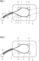
- FIG. 1 shows a schematic representation of a local RF coil 20 with several marker elements 4 according to an embodiment of the invention.
- the marker elements 4 may for example be capsules containing an MR visible fluid.
- the local RF coil 20 comprises a coil cable 28 with a fluid plug 26 which can be connected to ta tube connector 49 (not shown here).
- the coil cable 28 is configured to connect the coil 20 to a control unit 64 (not shown here) of the system.
- a fluid conducting element 8 is leading through the coil cable 28 and passing several electronic components 22.
- the fluid conducting element 8 may be connected to a source of air pressure or to another part of the fluid conducting element 8 filled, for example, with MR visible fluid, which may be pumped through the fluid conducting element, via the tube connector 49.
- the marker elements 4 may either be fixed at their position or they can be moved along the fluid conducting element 8, for example by air pressure. If the marker elements 4 are fixed at their position they may for example be activated and deactivated by shielding elements 12 (not shown here) which may for example be moved over the marker elements 4 via air pressure guided through the fluid conducting element 8.
- the electronic components 22 of the coil 20 can influence the imaging of other imaging methods carried out in parallel or consecutively to the MRI. For example, they may attenuate the signal of PET scans. It is therefore useful to correct this attenuation by calculating the effect of attenuation and adjusting the (PET) image data accordingly. For this, it is necessary to determine the position of the movable coil 20 and its components 22.
- the marker elements 4 are or can be positioned at predetermined positions with respect to the electronic components 22 of the coil 20 and since the marker elements 4 are highly visible in MRI images when activated they can be used to determine the position of the coil 20 and of the electronic components 22 of the coil 20.
- the coil cable 28 there is at least one braid-breaker 24 which can also influence measurement signals such as a PET signal.
- the position of the braid breaker can also be determined via two marker elements 4 which are placed before and after the braid breaker 24 inside the coil cable 28.
- FIG. 2 shows a schematic representation of a local RF coil 20 with a fluid conducting element 8 according to another embodiment of the invention.
- the marker element 4 is an MR visible fluid 6 which is pumped through the fluid conducting element 8.
- the MR visible fluid 6 can be pumped into and out of the fluid conducting element 8 inside the coil 20 and the coil cable 28 via the fluid plug 26 which can be connected to a corresponding tube connector 49.
- the MR visible fluid 6 is inside the coil 20 and thus the marker element 4 is activated, it will appear as a bright network in an MR image which can be used to determine the position and orientation of the coil 20.
- the fluid conducting element 8 is guiding the MR visible fluid 6 around the electronic components 22 of the coil 20.
- the MR visible fluid 6 is pumped out of the part of the fluid conducting element 8 that is inside the coil 20 and, via the fluid plug 26, into a part not inside the field of view of the scanner (not shown) and thus it does not disturb the MR imaging process.
- FIG 3 shows a schematic representation of a local RF coil 20 with several marker elements 4 according to another embodiment of the invention.
- the marker elements 4 are fixed to a cable 10.
- the cable 10 may in particular be a pull rope.
- the cable 10 or pull rope is guided by a hose or tube 11.
- the marker elements are within the scan range of the MRI system and are thus activated.
- the cable 10 inside the coil 20 and the coil cable 28 can be connected via a cable plug 27 to a cable part outside the coil 20.
- the cable part outside the coil 20 does not have marker elements 4 attached to it.
- the marker elements 4 can be pulled out of the coil 20 via the cable 10 such that there is only the part of the cable 10 without marker elements inside the coil 20 and the marker elements 4 can thus be deactivated by removing them from the coil via the cable 10. In order to activate the marker elements 4 again, they can be pulled back into the coil 20 to their predetermined position.
- FIG. 4 shows a marker element 4 with a shielding element 12 according to an embodiment of the invention.
- the shielding element 12 is attached to a cable 10 that is guided via a tube 11.
- the tube 11 may preferably be flexible, e.g. be a hose.
- the tube 11 comprises an opening 9 and the cable 10 is fixed to the shielding element 12 via a gripping unit 13.
- the shielding element 12 can be pushed over a marker element 4 comprising an MR visible fluid 6 in order to deactivate the marker element 4 by shielding it and pulled away from the marker element 4 in order to activate it.
- the cable 10 is pretensioned by a non-magnetic spring 18 such that, if no additional force is applied to the cable 10, the shielding element 12 is naturally kept in a position where it shields the marker element 4.
- the marker element is deactivated.
- the cable 10 can be pulled (to the left in the figure) such that the shielding element 12 is pulled (to the left) away from the marker element 4.
- the shielding element 12 is moved for a distance equivalent to the length of the marker element 4.
- the two directions of movement (towards the marker element and away from it) of the shielding element 12 are marked by an arrow.
- the marker element 4 and the shielding element 12 are comprised within a housing 15, in particular a housing 15 made of plastic, which is configured to guide the shielding element 12 when the shielding element 12 is pulled by the cable 10.
- the marker element 4, on the other hand, is fixed to the housing 15.
- the marker element 4 may for example have a diameter of 1 mm two 20 mm and a length (along the direction of the arrow) of 1 mm to 50 mm.
- the shielding element 12 on the other hand has a similar or essentially equal geometry, wherein its inner walls are dimensioned such that a gap of about 0,1 mm to 0,5 mm exists between the shielding element and the marker element.
- FIG. 5 shows a marker element 4 with a shielding element 12 according to another embodiment of the invention.
- the shielding element 12 is moved via air pressure.
- the air pressure is provided via a fluid conducting element 8 which is connected to a first portion 141 of an air pressure chamber 14 via an air inlet 36 in an airtight manner.
- Within the air pressure chamber 14 there are a marker element 4 and the shielding element 12.
- the marker element is fixed to a wall of a second portion 142 of the air pressure chamber and the shielding element 12 is arranged between the first portion 141 and the second portion 142 of the air pressure chamber 14.
- the shielding element 12 can be pushed over the marker element 4 by providing a positive pressure (overpressure) in the first portion 141 via the fluid conducting element 8.
- the shielding element 12 can be pulled away from the marker element 4 by providing a negative pressure (underpressure) in the first portion 141 via the fluid conducting element 8.
- the second portion comprises an air outlet (34) in order to ensure that the pressure in the second portion 142 can remain essentially constant, in particular remain at ambient pressure, to allow free movement of the shielding element 12 without creating counterpressure in the second portion 142 due to the movement of the shielding element 8.
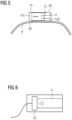
- Figure 6 shows a marker element 4 with an ultrasound emitter 16 according to an embodiment of the invention.
- the ultrasound emitter 16 is directly attached to the marker element 4.
- the marker element 4 can be deactivated via ultrasound waves created by the ultrasound emitter 16 by destroying the MR phase coherence of the marker element 4. Accordingly, the marker element 4 may be deactivated during an MRI measurement by the ultrasound waves.
- the marker element 4 is activated by switching off the ultrasound emitter 16.
- Figure 7 shows MRI images used for localization of the coil 20 via a marker element 4.
- the marker element 4 was deactivated by shielding it with an RF shield and is thus not visible on the MRI image.
- the marker element 4 was activated, i.e. not shielded, and thus appears as bright signal 38 in the MRI image.
- the right picture shows data, wherein the data of the left picture were subtracted from the data of the centred picture. Accordingly, the MRI image of the right picture only shows the bright signal 38 corresponding to the marker element 4. It is thus easier to determine the position of the marker element 4 within the field of view in order to determine the position of the coil 20, which is positioned at a predetermined position in relation to the marker element 4.
- Figure 8 shows a cable plug 27 connected to a cable connector 48 according to an embodiment of the invention.
- This connection can in particular be used to move a shielding element 12 via a cable 10 which is guided through a coil cable 28 of a coil 20.
- the MRI system comprises an MR compatible motor 42 which is configured to drive a rotary shaft 43 in order to rotate an eccentric 44.
- the motor 42, the rotary shaft and the eccentric 44 are located in or at a patient table 40.
- a bolt 43 within the cable connector 48 is pushed upwards against the force of a spring 19 thereby pushing a lever 50 inside the cable plug 27.
- the cable 10 is connected to the other end of the lever 50.
- the cable 10 is pulled in the direction of the cable connector 48.
- the cable 10 is connected to a shielding element 12 (see figure 4 ) and by pulling the cable 10, the shielding element 12 is pulled away from the marker element 4 thereby activating the marker element 4.
- the bolt 46 is no longer pushed by the eccentric 44 and is therefore pulled back by the spring 19 such that the lever 50 can also move back into its original position. Accordingly, the shielding element 12, for example due to the force of a further spring 18 inside the coil 20 as shown in figure 4 , can move over the marker element 4 and thus deactivate the marker element 4.
- Figure 9 shows a fluid plug 26 connected to a tube connector 49 according to an embodiment of the invention.
- the connection is in particular configured to allow the transfer of air into the fluid conducting element 8 of the coil 20.
- the tube connector 49 comprises an air socket 54 which is configured such, that the fluid plug of the coil 20 can be engage with the tube connector 49 thereby joining together the fluid conducting element 8 parts of the coil 20 and of the patient table 40.
- the configuration according to this embodiment may in particular be used to drive the shielding element 12, e.g. as shown in figure 5 .
- Figure 10 shows a fluid plug 26 connected to a tube connector 49 according to another embodiment of the invention.
- This configuration may in particular be used for an embodiment where the marker element 4 is an MR visible liquid 6 guided inside a fluid conducting element 8, e.g. for the embodiment shown in figure 2 , or for an embodiment wherein cooling liquid is guided into the coil 20.
- this embodiment has additional locking means. These are particularly useful in this case because a higher pressure may be needed to guide the MR visible liquid 6 as compared to guiding air and it is to be avoided that the MR visible liquid 6 might leak out when disconnecting the fluid plug 26.
- the tube connector and/or the fluid plug 26 comprise an unlocking button 56 which needs to be pushed before disconnecting the fluid plug 26.
- the fluid pump 52 is configured to pump the MR visible liquid out of the part of the fluid conducting element 8 that is located within the coil cable 28 and the coil 20.
- a locking element 58 is configured to ensures that a locking bolt 59 prevents removal of the fluid plug 26. After pumping the MR visible fluid 6 out of the coil 20 and coil cable 28, the locking bolt is pulled back and the fluid plug 26 can be removed.
- Figure 11 shows an electronic component 22 of a coil 20 with a ceramic element 30 according to an embodiment of the invention.
- the MR visible fluid 6 also serves as a cooling liquid.
- the electronic component 22 is encased in the ceramic element 30 which comprises a fluid channel 32 that is part of the fluid conducting element 8.
- the electronic component 22 is cooled by the MR visible fluid 6 via the ceramic element 30.
- a temperature sensor 60 is arranged within or at the electronic component 22.
- Figure 12 shows a magnetic resonance imaging system 1 of the MRI-PET system according to an embodiment of the invention, wherein the PET system of the MRI-PET system of the invention is not shown.
- the system 1 comprises a patient table 40 on which a patient may lie during an examination and a coil 20 comprising the inventive marker element 4.
- a diagnostic measurement, a localization of the coil 20 and/or an attenuation correction can be controlled and/or carried out by a control unit 64.
- Figure 13 shows a flow diagram of a method according to an embodiment of the invention.
- a marker element 4 is provided at a predetermined position relative to a coil in an activated state.
- a magnetic resonance measurement is taken with the magnetic resonance imaging system of the MRI-PET system while the marker element is activated in order to obtain first test data.
- the position of the marker element and thereby the position of the at least one coil is determined based on the first test data, in particular at the control unit.
- the marker element is deactivated for further MRI measurements.
- step 205 a magnetic resonance measurement may be taken with the MRI system when the marker element is deactivated in order to obtain second test data.
- step 206 the second test data may be subtracted from the first test data in order to obtain adjusted data, which are then used in step 203 instead of the test data for the localization of the coil 20.
Landscapes
- Physics & Mathematics (AREA)
- Health & Medical Sciences (AREA)
- Life Sciences & Earth Sciences (AREA)
- Nuclear Medicine, Radiotherapy & Molecular Imaging (AREA)
- Engineering & Computer Science (AREA)
- Condensed Matter Physics & Semiconductors (AREA)
- General Physics & Mathematics (AREA)
- General Health & Medical Sciences (AREA)
- High Energy & Nuclear Physics (AREA)
- Surgery (AREA)
- Radiology & Medical Imaging (AREA)
- Theoretical Computer Science (AREA)
- Pulmonology (AREA)
- Pathology (AREA)
- Biomedical Technology (AREA)
- Heart & Thoracic Surgery (AREA)
- Medical Informatics (AREA)
- Molecular Biology (AREA)
- Veterinary Medicine (AREA)
- Animal Behavior & Ethology (AREA)
- Public Health (AREA)
- Biophysics (AREA)
- Oral & Maxillofacial Surgery (AREA)
- Signal Processing (AREA)
- Magnetic Resonance Imaging Apparatus (AREA)
Claims (13)
- MRT-PET-System (1), bestehend aus einem Magnetresonanztomographie-, MRT-, System kombiniert mit einem Positronen-Emissions-Tomographie-, PET-, System, undumfassend mindestens eine lokale HF-Spule (20) und mindestens ein Markierungselement (4),wobei das MRT-PET-System (1) und das Markierungselement (4) derart ausgelegt sind, dass das mindestens eine Markierungselement (4) aktiviert werden kann, so dass es vom MRT-System (1) an einer vorbestimmten Position relativ zur Spule (20) detektierbar ist,wobei das MRT-PET-System (1) und das Markierungselement (4) derart ausgelegt sind, dass das mindestens eine Markierungselement (4) deaktiviert werden kann, so dass es vom MRT-System (1) nicht detektierbar ist,dadurch gekennzeichnet, dassdas MRT-PET-System (1) ein Abschirmelement (12) umfasst,wobei das Abschirmelement (12) derart beweglich ist, dass es in eine abschirmende Position und in eine nicht abschirmende Position bewegt werden kann, und/oder wobei das Markierungselement (4) derart beweglich ist, dass es in eine abschirmende Position und in eine nicht abschirmende Position bewegt werden kann,wobei das Abschirmelement (12) das Markierungselement (4) derart einschließt, dass das Markierungselement (4) vom MRT-PET-System (1) abgeschirmt ist, wenn sich das Abschirmelement (12) und/oder das Markierungselement (4) in der abschirmenden Position befindet, undwobei das Abschirmelement (12) vom Markierungselement (4) derart getrennt ist, dass das Markierungselement (4) vom MRT-System (1) detektierbar ist, wenn sich das Abschirmelement (12) und/oder das Markierungselement (4) in der nicht abschirmenden Position befindet.
- MRT-PET-System (1) nach Anspruch 1,
wobei das Markierungselement (4) ein magnetresonanzsichtbares Fluid (6), insbesondere eine Flüssigkeit, umfasst. - MRT-PET-System (1) nach einem der vorhergehenden Ansprüche, wobei das MRT-PET-System (1) ein Verlagerungssystem umfasst, das dazu ausgelegt ist, das Markierungselement (4) in Bezug auf die Spule (20) und/oder das MRT-PET-System (1) zu verlagern,
wobei das Verlagerungssystem dazu ausgelegt ist, das Markierungselement (4) durch Entfernen desselben von der Spule (20) und/oder aus dem Sichtfeld des MRT-Systems (1) zu deaktivieren und das Markierungselement (4) durch Bewegen desselben in eine vorbestimmte Position in der Nähe der Spule (20) oder innerhalb der Spule (20) zu aktivieren. - MRT-PET-System (1) nach den Ansprüchen 2 und 3,wobei das Verlagerungssystem ein Fluidleitungselement (8), insbesondere ein Rohr, das das magnetresonanzsichtbare Fluid (6) enthält, undeine Fluidpumpe umfasst,wobei das Fluidleitungselement (8) derart ausgelegt ist, dass ein erster Teil des Fluidleitungselements (8) an oder innerhalb der Spule (20) angeordnet ist und ein zweiter Teil des Fluidleitungselements (8) außerhalb des detektierbaren Bereichs des MRT-Systems (1) angeordnet ist,wobei die Fluidpumpe dazu ausgelegt ist, das magnetresonanzsichtbare Fluid (6) vom ersten Teil in den zweiten Teil und umgekehrt zu bewegen.
- MRT-PET-System (1) nach einem der Ansprüche 2 bis 4, wobei die Spule (20) mindestens ein Keramikelement (30) umfasst, das um mindestens ein elektronisches Bauteil der Spule (20) herum angeordnet ist,wobei das Keramikelement (30) mindestens einen Fluidkanal (32) umfasst, der mit dem Fluidleitungselement (8) verbunden ist, wobei das magnetresonanzsichtbare Fluid (6) dazu ausgelegt ist, als ein Kühlfluid zu arbeiten,wobei die Fluidpumpe dazu ausgelegt ist, das magnetresonanzsichtbare Fluid (6) durch den mindestens einen Fluidkanal zu bewegen.
- MRT-PET-System (1) nach einem der vorhergehenden Ansprüche, wobei das MRT-PET-System (1) einen Seilmechanismus umfasst, der dazu ausgelegt ist, das mindestens eine Markierungselement (4) zu aktivieren und zu deaktivieren.
- MRT-PET-System (1) nach einem der vorhergehenden Ansprüche, wobei das MRT-PET-System (1) einen Fördermechanismus, insbesondere einen Seilmechanismus, umfasst,
wobei der Fördermechanismus dazu ausgelegt ist, das mindestens eine Markierungselement (4) in Bezug auf die Spule (20) und/oder in den und aus dem detektierbaren Bereich des MRT-PET-Systems (1) zu bewegen, um die mindestens eine Markierung zu aktivieren und zu deaktivieren. - MRT-PET-System (1) nach Anspruch 7,wobei der Fördermechanismus ein bewegliches Seil (9) umfasst, das sich von der Spule (20) zu einem Bereich außerhalb des detektierbaren Bereichs des MRT-Systems (1) erstreckt,wobei das mindestens eine Markierungselement (4) derart am Seil (9) befestigt ist, dass es über das Seil (9) zwischen der Spule (20) und dem Bereich außerhalb des detektierbaren Bereichs des MRT-Systems (1) bewegt werden kann.
- MRT-PET-System (1) nach einem der vorhergehenden Ansprüche, wobei das mindestens eine Markierungselement (4) eine Kapsel ist, die ein magnetresonanzsichtbares Fluid (6), insbesondere eine Flüssigkeit, enthält.
- MRT-PET-System (1) nach einem der vorhergehenden Ansprüche, wobei das Abschirmelement (12) ein Rohr ist,
wobei das Abschirmelement (12) insbesondere aus Kohlenstofffasern besteht. - MRT-PET-System (1) nach einem der vorhergehenden Ansprüche, wobei das MRT-PET-System (1) eine Luftdruckkammer (14) und ein Fluidleitungselement (8), insbesondere einen Luftschlauch, umfasst, der mit der Luftdruckkammer (14) verbunden ist,wobei das Abschirmelement (12) und das Markierungselement (4) innerhalb der Luftdruckkammer (14) angeordnet sind,wobei die Luftdruckkammer (14) und das Abschirmelement (12) derart ausgelegt sind, dass das Abschirmelement (12) durch Luftdruck, der über das Fluidleitungselement (8) bereitgestellt wird, beweglich ist.
- MRT-PET-System (1) nach einem der vorhergehenden Ansprüche, wobei das MRT-PET-System (1) einen Seilmechanismus umfasst, wobei der Seilmechanismus dazu ausgelegt ist, das Abschirmelement (12) von der abschirmenden Position in die nicht abschirmende Position und/oder umgekehrt zu bewegen.
- MRT-PET-System (1) nach einem der vorhergehenden Ansprüche, wobei das MRT-PET-System (1) einen Ultraschallemitter (16) umfasst,wobei der Ultraschallemitter (16) insbesondere angrenzend an das Markierungselement (4) angeordnet ist,wobei der Ultraschallemitter (16) dazu ausgelegt ist, Ultraschallwellen am Markierungselement (4) bereitzustellen, um das Markierungselement (4) mit den Ultraschallwellen, insbesondere durch Zerstörung der Phasenkohärenz im Markierungselement (4), zu deaktivieren.
Priority Applications (3)
| Application Number | Priority Date | Filing Date | Title |
|---|---|---|---|
| EP21203537.2A EP4170375B1 (de) | 2021-10-19 | 2021-10-19 | Mrt-pet-system zur bestimmung der position mindestens einer spule in einer magnetresonanzbildgebung |
| US18/046,573 US12178668B2 (en) | 2021-10-19 | 2022-10-14 | Magnetic resonance imaging system and method for determining the position of at least one coil in a magnetic resonance imaging |
| CN202211281993.5A CN115990010A (zh) | 2021-10-19 | 2022-10-18 | 磁共振成像系统和在磁共振成像中确定线圈的位置的方法 |
Applications Claiming Priority (1)
| Application Number | Priority Date | Filing Date | Title |
|---|---|---|---|
| EP21203537.2A EP4170375B1 (de) | 2021-10-19 | 2021-10-19 | Mrt-pet-system zur bestimmung der position mindestens einer spule in einer magnetresonanzbildgebung |
Publications (3)
| Publication Number | Publication Date |
|---|---|
| EP4170375A1 EP4170375A1 (de) | 2023-04-26 |
| EP4170375B1 true EP4170375B1 (de) | 2024-12-18 |
| EP4170375C0 EP4170375C0 (de) | 2024-12-18 |
Family
ID=78535993
Family Applications (1)
| Application Number | Title | Priority Date | Filing Date |
|---|---|---|---|
| EP21203537.2A Active EP4170375B1 (de) | 2021-10-19 | 2021-10-19 | Mrt-pet-system zur bestimmung der position mindestens einer spule in einer magnetresonanzbildgebung |
Country Status (3)
| Country | Link |
|---|---|
| US (1) | US12178668B2 (de) |
| EP (1) | EP4170375B1 (de) |
| CN (1) | CN115990010A (de) |
Families Citing this family (1)
| Publication number | Priority date | Publication date | Assignee | Title |
|---|---|---|---|---|
| EP4571344A1 (de) | 2023-12-13 | 2025-06-18 | Siemens Healthineers AG | Bewegungsverfolgung eines objektbereichs in einem untersuchungstunnel eines magnetresonanztomographiesystems |
Family Cites Families (4)
| Publication number | Priority date | Publication date | Assignee | Title |
|---|---|---|---|---|
| EP2549284A1 (de) | 2011-07-21 | 2013-01-23 | Koninklijke Philips Electronics N.V. | Positionsmarker zur Verwendungen bei einer Magnetresonanzbildgebungsvorrichtung |
| US20130165767A1 (en) * | 2011-12-21 | 2013-06-27 | General Electric Company | Systems and methods for automatic landmarking |
| US10591570B2 (en) | 2012-12-17 | 2020-03-17 | The Board Of Trustees Of The Leland Stanford Junior University | Method for 3D motion tracking in an MRI scanner using inductively coupled microcoils |
| JP6615122B2 (ja) * | 2014-05-09 | 2019-12-04 | コーニンクレッカ フィリップス エヌ ヴェ | Mriモジュールと、rfコイルの位置を決定するための手段とを含む療法システム |
-
2021
- 2021-10-19 EP EP21203537.2A patent/EP4170375B1/de active Active
-
2022
- 2022-10-14 US US18/046,573 patent/US12178668B2/en active Active
- 2022-10-18 CN CN202211281993.5A patent/CN115990010A/zh active Pending
Also Published As
| Publication number | Publication date |
|---|---|
| EP4170375C0 (de) | 2024-12-18 |
| CN115990010A (zh) | 2023-04-21 |
| EP4170375A1 (de) | 2023-04-26 |
| US20230118471A1 (en) | 2023-04-20 |
| US12178668B2 (en) | 2024-12-31 |
Similar Documents
| Publication | Publication Date | Title |
|---|---|---|
| Lee | Fusion imaging of real-time ultrasonography with CT or MRI for hepatic intervention | |
| US5730134A (en) | System to monitor temperature near an invasive device during magnetic resonance procedures | |
| Kaiser et al. | Robotic system for biopsy and therapy of breast lesions in a high-field whole-body magnetic resonance tomography unit | |
| CN1637428B (zh) | Rf体线圈和磁共振成像系统 | |
| CN108072854B (zh) | 包括柔性局部线圈和刚性局部线圈的线圈装置 | |
| US5323776A (en) | MRI compatible pulse oximetry system | |
| Zangos et al. | MR-compatible assistance system for punction in a high-field system: device and feasibility of transgluteal biopsies of the prostate gland | |
| US9445721B2 (en) | MR gamma hybrid imaging system | |
| De Oliveira et al. | Automatic passive tracking of an endorectal prostate biopsy device using phase‐only cross‐correlation | |
| US8482278B2 (en) | Method of positioning and aligning with precision, a small animal in order to conduct and perform MRI measurements | |
| EP2713868B1 (de) | Bewegungskompensiertes magnetresonanz-bildgebungsverfahren und -system | |
| AU2021209677A1 (en) | MRI-guided robotic systems and methods for biopsy | |
| CN106539623A (zh) | 向刚性工具添加跟踪传感器 | |
| Ghate et al. | MRI-guided vacuum-assisted breast biopsy with a handheld portable biopsy system | |
| EP4170375A1 (de) | Magnetresonanzbildgebungssystem und verfahren zur bestimmung der position mindestens einer spule in einer magnetresonanzbildgebung | |
| Daniel et al. | Freehand iMRI‐guided large‐gauge core needle biopsy: a new minimally invasive technique for diagnosis of enhancing breast lesions | |
| Mo et al. | A novel three-channel endorectal coil for prostate magnetic resonance imaging at 3T | |
| Yakar et al. | Magnetic resonance-guided biopsy of the prostate: feasibility, technique, and clinical applications | |
| Busse et al. | Flexible add‐on solution for MR image‐guided interventions in a closed‐bore scanner environment | |
| JP2011030828A (ja) | 医用画像診断装置 | |
| JP3849853B2 (ja) | 手術用受信コイル及びこれを用いた磁気共鳴イメージング装置 | |
| JP2002528214A (ja) | 対象検査装置 | |
| CN101268380A (zh) | 在波谱成像中考虑移位的代谢体积的方法 | |
| US11940512B2 (en) | Systems and methods for body coil air cooling | |
| US20150031981A1 (en) | High-frequency antenna unit and a magnetic resonance apparatus with the high-frequency antenna unit |
Legal Events
| Date | Code | Title | Description |
|---|---|---|---|
| PUAI | Public reference made under article 153(3) epc to a published international application that has entered the european phase |
Free format text: ORIGINAL CODE: 0009012 |
|
| STAA | Information on the status of an ep patent application or granted ep patent |
Free format text: STATUS: THE APPLICATION HAS BEEN PUBLISHED |
|
| AK | Designated contracting states |
Kind code of ref document: A1 Designated state(s): AL AT BE BG CH CY CZ DE DK EE ES FI FR GB GR HR HU IE IS IT LI LT LU LV MC MK MT NL NO PL PT RO RS SE SI SK SM TR |
|
| STAA | Information on the status of an ep patent application or granted ep patent |
Free format text: STATUS: REQUEST FOR EXAMINATION WAS MADE |
|
| 17P | Request for examination filed |
Effective date: 20231005 |
|
| RBV | Designated contracting states (corrected) |
Designated state(s): AL AT BE BG CH CY CZ DE DK EE ES FI FR GB GR HR HU IE IS IT LI LT LU LV MC MK MT NL NO PL PT RO RS SE SI SK SM TR |
|
| RAP1 | Party data changed (applicant data changed or rights of an application transferred) |
Owner name: SIEMENS HEALTHINEERS AG |
|
| GRAP | Despatch of communication of intention to grant a patent |
Free format text: ORIGINAL CODE: EPIDOSNIGR1 |
|
| STAA | Information on the status of an ep patent application or granted ep patent |
Free format text: STATUS: GRANT OF PATENT IS INTENDED |
|
| RIC1 | Information provided on ipc code assigned before grant |
Ipc: G01R 33/48 20060101ALN20240710BHEP Ipc: G01R 33/54 20060101ALI20240710BHEP Ipc: G01R 33/34 20060101ALI20240710BHEP Ipc: G01R 33/58 20060101AFI20240710BHEP |
|
| INTG | Intention to grant announced |
Effective date: 20240726 |
|
| GRAS | Grant fee paid |
Free format text: ORIGINAL CODE: EPIDOSNIGR3 |
|
| GRAA | (expected) grant |
Free format text: ORIGINAL CODE: 0009210 |
|
| STAA | Information on the status of an ep patent application or granted ep patent |
Free format text: STATUS: THE PATENT HAS BEEN GRANTED |
|
| AK | Designated contracting states |
Kind code of ref document: B1 Designated state(s): AL AT BE BG CH CY CZ DE DK EE ES FI FR GB GR HR HU IE IS IT LI LT LU LV MC MK MT NL NO PL PT RO RS SE SI SK SM TR |
|
| REG | Reference to a national code |
Ref country code: CH Ref legal event code: EP |
|
| REG | Reference to a national code |
Ref country code: DE Ref legal event code: R096 Ref document number: 602021023494 Country of ref document: DE |
|
| REG | Reference to a national code |
Ref country code: IE Ref legal event code: FG4D |
|
| U01 | Request for unitary effect filed |
Effective date: 20241218 |
|
| U07 | Unitary effect registered |
Designated state(s): AT BE BG DE DK EE FI FR IT LT LU LV MT NL PT RO SE SI Effective date: 20250102 |
|
| PG25 | Lapsed in a contracting state [announced via postgrant information from national office to epo] |
Ref country code: HR Free format text: LAPSE BECAUSE OF FAILURE TO SUBMIT A TRANSLATION OF THE DESCRIPTION OR TO PAY THE FEE WITHIN THE PRESCRIBED TIME-LIMIT Effective date: 20241218 |
|
| PG25 | Lapsed in a contracting state [announced via postgrant information from national office to epo] |
Ref country code: NO Free format text: LAPSE BECAUSE OF FAILURE TO SUBMIT A TRANSLATION OF THE DESCRIPTION OR TO PAY THE FEE WITHIN THE PRESCRIBED TIME-LIMIT Effective date: 20250318 |
|
| PG25 | Lapsed in a contracting state [announced via postgrant information from national office to epo] |
Ref country code: GR Free format text: LAPSE BECAUSE OF FAILURE TO SUBMIT A TRANSLATION OF THE DESCRIPTION OR TO PAY THE FEE WITHIN THE PRESCRIBED TIME-LIMIT Effective date: 20250319 |
|
| PG25 | Lapsed in a contracting state [announced via postgrant information from national office to epo] |
Ref country code: RS Free format text: LAPSE BECAUSE OF FAILURE TO SUBMIT A TRANSLATION OF THE DESCRIPTION OR TO PAY THE FEE WITHIN THE PRESCRIBED TIME-LIMIT Effective date: 20250318 |
|
| PG25 | Lapsed in a contracting state [announced via postgrant information from national office to epo] |
Ref country code: SM Free format text: LAPSE BECAUSE OF FAILURE TO SUBMIT A TRANSLATION OF THE DESCRIPTION OR TO PAY THE FEE WITHIN THE PRESCRIBED TIME-LIMIT Effective date: 20241218 |
|
| PG25 | Lapsed in a contracting state [announced via postgrant information from national office to epo] |
Ref country code: PL Free format text: LAPSE BECAUSE OF FAILURE TO SUBMIT A TRANSLATION OF THE DESCRIPTION OR TO PAY THE FEE WITHIN THE PRESCRIBED TIME-LIMIT Effective date: 20241218 |
|
| PG25 | Lapsed in a contracting state [announced via postgrant information from national office to epo] |
Ref country code: ES Free format text: LAPSE BECAUSE OF FAILURE TO SUBMIT A TRANSLATION OF THE DESCRIPTION OR TO PAY THE FEE WITHIN THE PRESCRIBED TIME-LIMIT Effective date: 20241218 |
|
| PG25 | Lapsed in a contracting state [announced via postgrant information from national office to epo] |
Ref country code: IS Free format text: LAPSE BECAUSE OF FAILURE TO SUBMIT A TRANSLATION OF THE DESCRIPTION OR TO PAY THE FEE WITHIN THE PRESCRIBED TIME-LIMIT Effective date: 20250418 |
|
| PG25 | Lapsed in a contracting state [announced via postgrant information from national office to epo] |
Ref country code: SK Free format text: LAPSE BECAUSE OF FAILURE TO SUBMIT A TRANSLATION OF THE DESCRIPTION OR TO PAY THE FEE WITHIN THE PRESCRIBED TIME-LIMIT Effective date: 20241218 |
|
| PG25 | Lapsed in a contracting state [announced via postgrant information from national office to epo] |
Ref country code: CZ Free format text: LAPSE BECAUSE OF FAILURE TO SUBMIT A TRANSLATION OF THE DESCRIPTION OR TO PAY THE FEE WITHIN THE PRESCRIBED TIME-LIMIT Effective date: 20241218 |
|
| PLBE | No opposition filed within time limit |
Free format text: ORIGINAL CODE: 0009261 |
|
| STAA | Information on the status of an ep patent application or granted ep patent |
Free format text: STATUS: NO OPPOSITION FILED WITHIN TIME LIMIT |
|
| 26N | No opposition filed |
Effective date: 20250919 |
|
| U20 | Renewal fee for the european patent with unitary effect paid |
Year of fee payment: 5 Effective date: 20251020 |
|
| PGFP | Annual fee paid to national office [announced via postgrant information from national office to epo] |
Ref country code: GB Payment date: 20251111 Year of fee payment: 5 |