EP4170340A1 - Gas chromatography instrument for autonomously determining a concentration of a volatile marker in a liquid sample - Google Patents
Gas chromatography instrument for autonomously determining a concentration of a volatile marker in a liquid sample Download PDFInfo
- Publication number
- EP4170340A1 EP4170340A1 EP21204430.9A EP21204430A EP4170340A1 EP 4170340 A1 EP4170340 A1 EP 4170340A1 EP 21204430 A EP21204430 A EP 21204430A EP 4170340 A1 EP4170340 A1 EP 4170340A1
- Authority
- EP
- European Patent Office
- Prior art keywords
- gas
- liquid
- chromatography instrument
- gas chromatography
- sample
- Prior art date
- Legal status (The legal status is an assumption and is not a legal conclusion. Google has not performed a legal analysis and makes no representation as to the accuracy of the status listed.)
- Withdrawn
Links
- 239000007788 liquid Substances 0.000 title claims abstract description 69
- 238000004817 gas chromatography Methods 0.000 title claims abstract description 42
- 239000003550 marker Substances 0.000 title claims abstract description 27
- 238000005070 sampling Methods 0.000 claims abstract description 60
- 238000006243 chemical reaction Methods 0.000 claims abstract description 33
- 239000007789 gas Substances 0.000 claims description 79
- 239000012530 fluid Substances 0.000 claims description 31
- 238000000197 pyrolysis Methods 0.000 claims description 28
- 239000012159 carrier gas Substances 0.000 claims description 27
- 238000000034 method Methods 0.000 claims description 17
- 238000002470 solid-phase micro-extraction Methods 0.000 claims description 16
- 239000012528 membrane Substances 0.000 claims description 15
- 238000004590 computer program Methods 0.000 claims description 10
- 150000001875 compounds Chemical class 0.000 claims description 9
- 238000011010 flushing procedure Methods 0.000 claims description 9
- 239000012466 permeate Substances 0.000 claims description 7
- 238000004458 analytical method Methods 0.000 claims description 6
- 238000010438 heat treatment Methods 0.000 claims description 6
- 239000012465 retentate Substances 0.000 claims description 5
- 239000000463 material Substances 0.000 claims description 4
- 238000012544 monitoring process Methods 0.000 abstract description 6
- 239000012080 ambient air Substances 0.000 description 10
- 238000001514 detection method Methods 0.000 description 8
- 239000012855 volatile organic compound Substances 0.000 description 7
- 230000008901 benefit Effects 0.000 description 6
- QVGXLLKOCUKJST-UHFFFAOYSA-N atomic oxygen Chemical compound [O] QVGXLLKOCUKJST-UHFFFAOYSA-N 0.000 description 4
- 230000009286 beneficial effect Effects 0.000 description 4
- 238000009835 boiling Methods 0.000 description 4
- 239000001301 oxygen Substances 0.000 description 4
- 229910052760 oxygen Inorganic materials 0.000 description 4
- 239000000126 substance Substances 0.000 description 4
- 230000001419 dependent effect Effects 0.000 description 3
- 239000012634 fragment Substances 0.000 description 3
- 238000004811 liquid chromatography Methods 0.000 description 3
- 238000005259 measurement Methods 0.000 description 3
- 239000000203 mixture Substances 0.000 description 3
- 238000010943 off-gassing Methods 0.000 description 3
- 230000003287 optical effect Effects 0.000 description 3
- 235000002918 Fraxinus excelsior Nutrition 0.000 description 2
- 238000010521 absorption reaction Methods 0.000 description 2
- 239000002956 ash Substances 0.000 description 2
- 239000011248 coating agent Substances 0.000 description 2
- 238000000576 coating method Methods 0.000 description 2
- 239000012141 concentrate Substances 0.000 description 2
- DDRJAANPRJIHGJ-UHFFFAOYSA-N creatinine Chemical compound CN1CC(=O)NC1=N DDRJAANPRJIHGJ-UHFFFAOYSA-N 0.000 description 2
- 238000003795 desorption Methods 0.000 description 2
- 230000000694 effects Effects 0.000 description 2
- 230000005484 gravity Effects 0.000 description 2
- JYGXADMDTFJGBT-VWUMJDOOSA-N hydrocortisone Chemical compound O=C1CC[C@]2(C)[C@H]3[C@@H](O)C[C@](C)([C@@](CC4)(O)C(=O)CO)[C@@H]4[C@@H]3CCC2=C1 JYGXADMDTFJGBT-VWUMJDOOSA-N 0.000 description 2
- 230000002209 hydrophobic effect Effects 0.000 description 2
- 238000002347 injection Methods 0.000 description 2
- 239000007924 injection Substances 0.000 description 2
- 238000005373 pervaporation Methods 0.000 description 2
- 239000012071 phase Substances 0.000 description 2
- 238000005086 pumping Methods 0.000 description 2
- 230000035945 sensitivity Effects 0.000 description 2
- 239000002594 sorbent Substances 0.000 description 2
- 241000894007 species Species 0.000 description 2
- WQZGKKKJIJFFOK-GASJEMHNSA-N Glucose Natural products OC[C@H]1OC(O)[C@H](O)[C@@H](O)[C@@H]1O WQZGKKKJIJFFOK-GASJEMHNSA-N 0.000 description 1
- 238000013459 approach Methods 0.000 description 1
- WQZGKKKJIJFFOK-VFUOTHLCSA-N beta-D-glucose Chemical compound OC[C@H]1O[C@@H](O)[C@H](O)[C@@H](O)[C@@H]1O WQZGKKKJIJFFOK-VFUOTHLCSA-N 0.000 description 1
- 239000000090 biomarker Substances 0.000 description 1
- 238000004587 chromatography analysis Methods 0.000 description 1
- 238000010276 construction Methods 0.000 description 1
- 235000020247 cow milk Nutrition 0.000 description 1
- 229940109239 creatinine Drugs 0.000 description 1
- 238000013461 design Methods 0.000 description 1
- 238000013467 fragmentation Methods 0.000 description 1
- 238000006062 fragmentation reaction Methods 0.000 description 1
- 239000008103 glucose Substances 0.000 description 1
- 229960001031 glucose Drugs 0.000 description 1
- 229960000890 hydrocortisone Drugs 0.000 description 1
- 239000002207 metabolite Substances 0.000 description 1
- 239000000047 product Substances 0.000 description 1
- 238000012882 sequential analysis Methods 0.000 description 1
- 239000002689 soil Substances 0.000 description 1
- 239000000243 solution Substances 0.000 description 1
- 239000000758 substrate Substances 0.000 description 1
- 230000002485 urinary effect Effects 0.000 description 1
- 210000002700 urine Anatomy 0.000 description 1
- XLYOFNOQVPJJNP-UHFFFAOYSA-N water Substances O XLYOFNOQVPJJNP-UHFFFAOYSA-N 0.000 description 1
Images


Classifications
-
- G—PHYSICS
- G01—MEASURING; TESTING
- G01N—INVESTIGATING OR ANALYSING MATERIALS BY DETERMINING THEIR CHEMICAL OR PHYSICAL PROPERTIES
- G01N30/00—Investigating or analysing materials by separation into components using adsorption, absorption or similar phenomena or using ion-exchange, e.g. chromatography or field flow fractionation
- G01N30/02—Column chromatography
- G01N30/04—Preparation or injection of sample to be analysed
- G01N30/06—Preparation
- G01N30/12—Preparation by evaporation
-
- G—PHYSICS
- G01—MEASURING; TESTING
- G01N—INVESTIGATING OR ANALYSING MATERIALS BY DETERMINING THEIR CHEMICAL OR PHYSICAL PROPERTIES
- G01N30/00—Investigating or analysing materials by separation into components using adsorption, absorption or similar phenomena or using ion-exchange, e.g. chromatography or field flow fractionation
- G01N30/02—Column chromatography
- G01N30/88—Integrated analysis systems specially adapted therefor, not covered by a single one of the groups G01N30/04 - G01N30/86
-
- G—PHYSICS
- G01—MEASURING; TESTING
- G01N—INVESTIGATING OR ANALYSING MATERIALS BY DETERMINING THEIR CHEMICAL OR PHYSICAL PROPERTIES
- G01N30/00—Investigating or analysing materials by separation into components using adsorption, absorption or similar phenomena or using ion-exchange, e.g. chromatography or field flow fractionation
- G01N30/02—Column chromatography
- G01N30/04—Preparation or injection of sample to be analysed
- G01N30/06—Preparation
- G01N2030/067—Preparation by reaction, e.g. derivatising the sample
-
- G—PHYSICS
- G01—MEASURING; TESTING
- G01N—INVESTIGATING OR ANALYSING MATERIALS BY DETERMINING THEIR CHEMICAL OR PHYSICAL PROPERTIES
- G01N30/00—Investigating or analysing materials by separation into components using adsorption, absorption or similar phenomena or using ion-exchange, e.g. chromatography or field flow fractionation
- G01N30/02—Column chromatography
- G01N30/62—Detectors specially adapted therefor
- G01N30/78—Detectors specially adapted therefor using more than one detector
Definitions
- the invention relates to a gas chromatography instrument, method and computer program for autonomously determining a concentration of a volatile marker in a liquid sample.
- a gas chromatography instrument is a well-known instrument for detecting and determining the concentration of gas compounds. It consists of a chromatographic column that has the ability to separate a mixture of gasses into individual components, and a detector that outputs a signal depending on the concentration and/or type of gas that passes through it.
- sample loops allow for an analysis of gas samples, only. Hence, for applications in which a continuous or semi-continuous monitoring of liquids is required, such devices cannot be used in a satisfactory way.
- a gas chromatography instrument for autonomously determining a concentration of a volatile marker in a liquid sample
- the instrument comprising a sampling device configured for autonomously sampling a liquid to be analyzed, a gas sensor, and a conversion device connected to the sampling device and the gas sensor, wherein the conversion device is configured to autonomously convert the sampled liquid into a gas to be analyzed by the gas sensor.
- a semi-continuous operation may be conducted, for example, at least hourly.
- the proposed gas chromatography instrument may be utilized in agricultural settings for monitoring relevant substances in the substrate or soil water of plants, cow milk or urine collected in the floor of a barn.
- Another field of application is human healthcare at which relevant biomarkers may be monitored such as creatinine, glucose and cortisol levels from a patient's bloodline or urinary catheter at the hospital bedside or at home.
- the sampling device is connected to a fluid sampling inlet and to a fluid sampling outlet, wherein fluid to be analyzed is provided by the fluid sampling inlet continuously or semi-continuously.
- the gas sensor preferentially comprises a chromatographic column connected to a detector. In this way, conventional chromatographic columns and detectors having superior performance in terms of re-usability, reliability and affordability can be utilized.
- the gas sensor comprises a detector, wherein the detector comprises multiple non-identical sensors.
- the detector comprises multiple non-identical sensors.
- the function of the chromatographic column is provided by the detector comprising the multiple non-identical sensors.
- an array of sensors may be utilized.
- the sensors may detect gases based on known techniques like chemoresistive, electro-chemical and optical absorption.
- the embodiment provides the benefit of a higher measurement speed compared to a solution comprising a chromatographic column and a detector.
- the multiple non-identical sensors comprise different sensor materials and/or operating conditions.
- the conversion device comprises a droplet dispenser connected to the sampling device, and a pyrolysis well that is configured to convert droplets provided by the droplet dispenser into gas, in particular, by means of heating.
- the pyrolysis well can beneficially convert non-volatile metabolites into multiple volatile fragments that can be detected with gas chromatography.
- the carrier gas provided to the pyrolysis well does not contain oxygen to avoid a complete conversion to CO 2 .
- the pyrolysis in the pyrolysis well can be performed by rapidly heating the wall of the pyrolysis well, either resistively or by means of RF coil, in particular utilizing the curie effect.
- the droplet can be transported by pressure, e.g. piezo, gravity or electrowetting.
- the pyrolysis well may utilize split/splitless injection of liquids, heated in the well above their boiling points.
- the temperature can be lower than the boiling point, since the rapid heating in absence of oxygen breaks molecules into volatile fragments.
- the fragmentation may depend on temperature, which allows for the optional benefit to achieve extra selectivity of marker detection, by performing sequential analysis runs at different pyrolysis temperatures.
- the sampling device comprises a liquid filter connected to the fluid inlet, wherein the liquid filter provides a retentate stream and a permeate stream, and wherein either of the retentate stream or the permeate stream is connected to the conversion device, in particular the droplet dispenser.
- the additional liquid filter enhances selectivity for sample liquids containing mixtures of markers.
- the liquid filter may be configured as a liquid chromatography column, to which sample fluid is injected. The output of the liquid chromatography column is fed to the droplet dispenser or any alternative liquid-to-gas converter. For this embodiment, it is beneficial to repeat the liquid-to-gas conversion multiple times, since at different times different compounds will reach the output of the liquid chromatography column.
- the conversion device comprises a liquid-to-gas-converter that is configured to convert liquid sampled by the sampling device into gas, and a valve arrangement, wherein the valve arrangement is configured to provide the following modes of operation: a feeding mode in which the sampling device is connected to the liquid-to-gas-converter to fill the liquid-to-gas-converter with the liquid sample, a flushing mode in which a carrier gas source is connected to the liquid-to-gas-converter for flushing excess fluid using carrier gas, and an analysis mode in which the liquid-to-gas-converter is connected to the gas sensor.
- the liquid-to-gas-converter can be configured as a pyrolysis well or a solid-phase microextraction device (SPME).
- the conversion device may comprise a six-port-valve connected to the sampling device, the carrier gas source and the gas sensor.
- the gas chromatography instrument may further comprise a valve arranged between the liquid-to-gas-converter and the gas sensor, wherein the valve comprises at least three ports, and wherein a first port is connected to the liquid-to-gas-converter, a second port is connected to the gas sensor and a third port is connected to an outlet.
- the liquid-to-gas-converter comprises a six-port-valve.
- the advantage of a high robustness is achieved, since possible non-volatile ashes that may remain in the pyrolysis well are flushed away in the next sampling phase.
- the surface area next to the pyrolysis well is covered with hydrophobic coating to facilitate the flushing step.
- the SPME is preferably heated gradually or stepwise to achieve desorption of selective volatile species to facilitate selective detection.
- ambient air is used as carrier gas. Due to the SPME sampling, analytes are upconcentrated, resulting in high sensitivity of detection.
- the conversion device comprises a membrane connected to the sampling device and the gas sensor, wherein the membrane is configured to outgas volatile compounds from the liquid sample. This outgassing is also called pervaporation.
- the conversion device comprises three-way valves to allow closing a gas chamber below the membrane to up-concentrate volatile compounds and collectively inject them into the gas sensor. The liquid above the membrane can be heated to enhance the outgassing rate, allowing detection of less volatile compounds.
- the membrane is connected to a carrier gas source, wherein ambient air is provided as carrier gas. It is preferred to use a volatile organic compounds (VOC) filter, to filter the ambient air before providing it to the conversion device.
- VOC volatile organic compounds
- the VOC filter removes VOCs present in the sampled ambient air as clean reference. This approach is beneficial compared to carrier gas from a pressurized cylinder, because the embodiment allows having extra underpressure in a gas chamber below the membrane.
- the chromatography instrument comprises a processor, wherein the processor is configured to carry out the steps of the method as defined in claim 15.
- a method for autonomously determining a concentration of a volatile marker in a liquid sample using gas chromatography comprises autonomously providing a sample fluid to be analyzed, autonomously converting at least part of the sample fluid into a gas sample, and autonomously determining a marker concentration in the gas sample.
- a computer program for autonomously determining a concentration of a marker in a sample comprising program code means for causing an instrument as defined in any of claims 1 to 13 to carry out the steps of the method as defined in claim 14, when the computer program is run on a computer controlling the instrument.
- Fig. 1 shows a first embodiment of a gas chromatography instrument 2 for determining a concentration of a volatile marker in a liquid sample.
- the gas chromatography instrument 2 comprises a sampling device 8.
- the sampling device 8 is configured to automatically sample a liquid that is provided by a fluid sampling inlet 4.
- the sampling device 8 is furthermore connected to a fluid sampling outlet 6.
- the sampling device 8 is fluidically connected to a conversion device 12.
- the conversion device 12 is configured to convert the provided liquid from the sampling device 8 into gas.
- the gas generated in the conversion device is supplied to a gas sensor 14.
- the gas sensor 14 is configured to analyze a concentration of a volatile marker in the provided gas sample.
- the gas sensor 14 is connected to a gas outlet 16.
- the gas chromatography instrument 2 allows for an automated, in particular semi-continuous, monitoring of relevant markers in liquid samples.
- the gas sensor 14 may comprise conventional sensing means. These conventional sensing means typically have superior performance in terms of re-usability, reliability and affordability compared to liquid sensors used in the prior art.
- the sampling device 8 comprises a fluid pump 18 for pumping the sampling fluid from the fluid sampling inlet 4 to the fluid sampling outlet 6 and towards the conversion device 12.
- the conversion device 12 comprises a droplet dispenser that is fluidically connected to the sampling device 8.
- the droplet dispenser 26 generates droplets of the sample liquid that are dispensed to a pyrolysis well 28.
- the pyrolysis well 28 is heated to convert the sample droplets into volatile markers that are carried to the gas sensor 14.
- the gas sensor 14 comprises a chromatographic column 22 and a detector 24 connected to the chromatographic column 22.
- the gas comprising the volatile markers that is generated in the pyrolysis well 28 is provided to the chromatographic column along with carrier gas supplied by the carrier gas source 10.
- the detector 24 records the output of the chromatographic column 22 as a function of time to establish a chromatogram.
- different temperatures may be used at the pyrolysis well 28 and the measurement process may be conducted repeatedly for different temperatures.
- the carrier gas source 10 does not contain oxygen to avoid complete conversion to CO 2 .
- the pyrolysis well 28 may comprise a wall that can be heated rapidly, wherein the heating may be conducted by means of an RF coil or resistively.
- the droplets can be transported by pressure, for example using the piezo-effect, gravity or electrowetting.
- the pyrolysis well 28 includes the widely used split/splitless injection of liquids, heated in the well above their boiling points.
- the temperature can be lower than the boiling point, since the rapid heating in absence of oxygen breaks molecules into volatile fragments.
- Fig. 3 shows an alternative embodiment of a gas chromatography instrument 2.
- Fig. 3 proposes an alternative design of the gas sensor 14.
- the gas sensor 14 of Fig. 3 only comprises a detector 24.
- the detector 24 is preferably composed of multiple non-identical sensors, for instance, an array of sensors composed of different sensor materials and/or operating conditions. Thereby, the selectivity of the instrument 2 is improved.
- the individual sensors may detect gases based on known techniques like chemoresistive, electro-chemical and optical absorption. All in all, compared to the embodiment of Fig. 2 , the measurement speed may be improved with the configuration of Fig. 3 .
- Fig. 4 shows yet another alternative embodiment of a gas chromatography instrument 2.
- the conversion device 12 comprises a liquid-to-gas-converter 30 that is configured to convert liquid sampled by the sampling device 8 into gas.
- the liquid-to-gas-converter 30 is configured as a pyrolysis well 28 connected to a valve arrangement 31 that is configured as a six-port-valve 32.
- the valve arrangement 31 may be switched to a feeding mode in which the sampling device 8 is fluidically connected to the liquid-to-gas-converter 30 to fill the liquid-to-gas-converter 30 with the liquid sample, and a flushing mode in which a carrier gas source 10 is fluidically connected to the liquid-to-gas-converter 30 for flushing excess fluid using carrier gas and an analysis mode in which the liquid-to-gas-converter 30 is fluidically connected to the gas sensor 14. Switching between the mentioned modes is conducted by means of the six-port-valve 32.
- the conversion device 12 furthermore comprises a valve 34 arranged between the six-port-valve 32 and the gas sensor 14.
- the valve 34 comprises three ports 36, 38, 40.
- the first port 36 is connected to the six-port-valve 32.
- the second port 38 is connected to the gas sensor 14 and the third port 40 is connected to an outlet 42.
- the gas sensor 14 comprises the chromatographic column 22 and the detector 24.
- the pyrolysis well 28 is filled with the sample liquid, when the six-port-valve 32 is in the dotted position. Afterwards, in the flushing mode, the excess fluid is flushed dry using carrier gas provided by the carrier gas source 10 and vented via the outlet 42. Therefore, the six-port-valve 32 is switched into the position illustrated with the dashed black line. Afterwards, in the analysis mode, the pyrolysis well 28 is heated. The resulting volatile pyrolysis products are transported with the help of the carrier gas to the gas sensor 14. Optionally, a surface area next to the pyrolysis well 28 is covered with hydrophobic coating to facilitate the flushing step. This embodiment has been found to be robust, since the possible non-volatile ashes remaining in the pyrolysis well 28 are flushed away in the next sampling phase.
- the conversion device 12 and the gas sensor 14 are equal to the embodiment of Fig. 2 .
- the sampling device 8 configuration however differs.
- the sampling device 8 comprises the fluid pump 18 pumping sampling fluid from the fluid sampling inlet 4 to a liquid filter 44.
- the liquid filter 44 provides a retentate stream 46 and a permeate stream 48.
- the permeate stream 48 is connected to the conversion device 12, in particular, to the droplet dispenser 26.
- the advantage of a higher selectivity notably for a sample liquid containing mixtures of markers are achieved by means of the liquid filter 44.
- a membrane 54 is utilized to outgas volatile compounds from a liquid sample provided by the sampling device 8. This is also called pervaporation.
- the valves 50, 52 allow to close a gas volume defined by a lower part of the membrane 54 to up-concentrate volatile compounds (in the dashed black position) and collectively inject them into the chromatographic column 22 of the gas sensor 14.
- carrier gas ambient air is provided by an ambient air inlet 56.
- the ambient air is filtered by a VOC filter 58 before reaching the membrane 54.
- the pressure controller 20 is arranged downstream of the gas sensor 14. With the help of a pump 60, the carrier gas comprising the volatile markers is guided towards a gas outlet 16.
- ambient air filtered by a VOC filter 58 is beneficial compared to the use of carrier gas from a pressurized cylinder, because this embodiment allows to have, in particular extra, underpressure below the membrane 54.
- the liquid provided by the sampling device 8 above the membrane 54 is heated to enhance the outgassing rate, allowing detection of less volatile compounds. All in all, the embodiment shown in Fig. 6 is simpler and ambient air may be used as carrier gas.
- Fig. 7 shows an alternative embodiment also utilizing a membrane 54.
- the gas sensor 14 only comprises a detector 24.
- the valves 50, 52 By removing the chromatographic column 22 (see Fig. 6 ) from the gas sensor 14, it is also possible to remove the valves 50, 52 and allow for a continuous detection of the gases that permeate through the membrane 54.
- Fig. 8 shows yet another alternative embodiment of a gas chromatography instrument 2 that is similar to the embodiment of Fig. 4 .
- the pyrolysis well 28 is replaced by a solid-phase microextraction device (SPME) 62.
- SPME solid-phase microextraction device
- Solid-phase microextraction (SPME) sorbents are used to extract analytes from the sampled liquid when the six-port-valve 32 is switched to the dotted position. Afterwards, the SPME 62 sorbents are flushed dry using carrier gas in the dashed position of the six-port-valve 32. Excess fluid is vented via the outlet 42. After the SPME 62 is flushed dry, it is heated and resulting desorbed VOCs are transported to and analyzed by the gas sensor 14. The SPME 62 may be heated gradually or stepwise to achieve desorption of selective volatile species to facilitate selective detection. The embodiment of Fig. 8 is beneficial, because ambient air may be used as carrier gas and analyzed or up-concentrated during SPME sampling, resulting in high sensitivity of detection.
- Fig. 9 shows an embodiment of a method 100 for autonomously determining a concentration of a volatile marker in a liquid sample using gas chromatography.
- the method 100 comprises the steps of autonomously providing 102 a sample fluid to be analyzed, autonomously converting 104 at least part of the sample fluid into a gas sample, and autonomously determining 106 a marker concentration in the gas sample.
- a single unit or device may fulfill the functions of several items recited in the claims.
- the mere fact that certain measures are recited in mutually different dependent claims does not indicate that a combination of these measures cannot be used to advantage.
- a computer program may be stored/distributed on a suitable medium, such as an optical storage medium or a solid-state medium, supplied together with or as part of other hardware, but may also be distributed in other forms, such as via the Internet or other wired or wireless telecommunication systems.
- a suitable medium such as an optical storage medium or a solid-state medium, supplied together with or as part of other hardware, but may also be distributed in other forms, such as via the Internet or other wired or wireless telecommunication systems.
- the invention relates to a gas chromatography instrument for autonomously determining a concentration of a volatile marker in a liquid sample.
- the instrument comprises a sampling device configured for autonomously sampling a liquid to be analyzed, a gas sensor, and a conversion device connected to the sampling device and the gas sensor.
- a conversion device that is configured to autonomously convert the sampled liquid into a gas to be analyzed by the gas sensor, an automated continuous monitoring of relevant markers in liquid samples is achieved.
Abstract
The invention relates to a gas chromatography instrument 2 for autonomously determining a concentration of a volatile marker in a liquid sample. The instrument 2 comprises a sampling device 8 configured for autonomously sampling a liquid to be analyzed, a gas sensor 14, and a conversion device 12 connected to the sampling device 8 and the gas sensor 14. By utilizing a conversion device 12 that is configured to autonomously convert the sampled liquid into a gas to be analyzed by the gas sensor 14, an automated continuous monitoring of relevant markers in liquid samples is achieved.
Description
- The invention relates to a gas chromatography instrument, method and computer program for autonomously determining a concentration of a volatile marker in a liquid sample.
- A gas chromatography instrument is a well-known instrument for detecting and determining the concentration of gas compounds. It consists of a chromatographic column that has the ability to separate a mixture of gasses into individual components, and a detector that outputs a signal depending on the concentration and/or type of gas that passes through it.
- From the prior art, chromatographic instruments are known that allow for a continuous or semi-continuous monitoring of a gas sample utilizing a so-called sample loop. However, sample loops allow for an analysis of gas samples, only. Hence, for applications in which a continuous or semi-continuous monitoring of liquids is required, such devices cannot be used in a satisfactory way.
- Other devices known from the prior art allow for an analysis of liquid samples, but require providing single liquid doses manually, not autonomously. Such devices are known from
US 9 435 772 B2 EP 2 924 429 A1 . - It is an object of the present invention to provide a gas chromatography instrument, method and computer program for autonomously determining a concentration of a volatile marker in a liquid sample.
- In a first aspect, a gas chromatography instrument for autonomously determining a concentration of a volatile marker in a liquid sample is presented, the instrument comprising a sampling device configured for autonomously sampling a liquid to be analyzed, a gas sensor, and a conversion device connected to the sampling device and the gas sensor, wherein the conversion device is configured to autonomously convert the sampled liquid into a gas to be analyzed by the gas sensor.
- It has been found that by automatically and continuously sampling a liquid to be analyzed and then convert the liquid into a gas that can be analyzed by a gas sensor, multiple types of gas sensors are available that have superior performance in terms of re-usability, reliability and affordability compared to liquid sensors known from the prior art to analyze liquid samples.
- The term autonomously is to be understood within this application as continuous or semi-continuous operation, without requiring manual activities from a human operator in the stages between the liquid sampling input stage and sensor output stage. A semi-continuous operation may be conducted, for example, at least hourly.
- The proposed gas chromatography instrument may be utilized in agricultural settings for monitoring relevant substances in the substrate or soil water of plants, cow milk or urine collected in the floor of a barn. Another field of application is human healthcare at which relevant biomarkers may be monitored such as creatinine, glucose and cortisol levels from a patient's bloodline or urinary catheter at the hospital bedside or at home.
- In a preferred embodiment, the sampling device is connected to a fluid sampling inlet and to a fluid sampling outlet, wherein fluid to be analyzed is provided by the fluid sampling inlet continuously or semi-continuously. The gas sensor preferentially comprises a chromatographic column connected to a detector. In this way, conventional chromatographic columns and detectors having superior performance in terms of re-usability, reliability and affordability can be utilized.
- Alternatively, the gas sensor comprises a detector, wherein the detector comprises multiple non-identical sensors. In this embodiment, it is not required to provide a chromatographic column. Instead, the function of the chromatographic column is provided by the detector comprising the multiple non-identical sensors. In particular, an array of sensors may be utilized. The sensors may detect gases based on known techniques like chemoresistive, electro-chemical and optical absorption. The embodiment provides the benefit of a higher measurement speed compared to a solution comprising a chromatographic column and a detector. Preferably, the multiple non-identical sensors comprise different sensor materials and/or operating conditions.
- According to one embodiment, the conversion device comprises a droplet dispenser connected to the sampling device, and a pyrolysis well that is configured to convert droplets provided by the droplet dispenser into gas, in particular, by means of heating. The pyrolysis well can beneficially convert non-volatile metabolites into multiple volatile fragments that can be detected with gas chromatography. Preferably, the carrier gas provided to the pyrolysis well does not contain oxygen to avoid a complete conversion to CO2. The pyrolysis in the pyrolysis well can be performed by rapidly heating the wall of the pyrolysis well, either resistively or by means of RF coil, in particular utilizing the curie effect. The droplet can be transported by pressure, e.g. piezo, gravity or electrowetting. Furthermore, the pyrolysis well may utilize split/splitless injection of liquids, heated in the well above their boiling points. For the pyrolysis, the temperature can be lower than the boiling point, since the rapid heating in absence of oxygen breaks molecules into volatile fragments. Preferably, the fragmentation may depend on temperature, which allows for the optional benefit to achieve extra selectivity of marker detection, by performing sequential analysis runs at different pyrolysis temperatures.
- According to one embodiment, the sampling device comprises a liquid filter connected to the fluid inlet, wherein the liquid filter provides a retentate stream and a permeate stream, and wherein either of the retentate stream or the permeate stream is connected to the conversion device, in particular the droplet dispenser. The additional liquid filter enhances selectivity for sample liquids containing mixtures of markers. According to an alternative embodiment, the liquid filter may be configured as a liquid chromatography column, to which sample fluid is injected. The output of the liquid chromatography column is fed to the droplet dispenser or any alternative liquid-to-gas converter. For this embodiment, it is beneficial to repeat the liquid-to-gas conversion multiple times, since at different times different compounds will reach the output of the liquid chromatography column.
- According to one embodiment, the conversion device comprises a liquid-to-gas-converter that is configured to convert liquid sampled by the sampling device into gas, and a valve arrangement, wherein the valve arrangement is configured to provide the following modes of operation: a feeding mode in which the sampling device is connected to the liquid-to-gas-converter to fill the liquid-to-gas-converter with the liquid sample, a flushing mode in which a carrier gas source is connected to the liquid-to-gas-converter for flushing excess fluid using carrier gas, and an analysis mode in which the liquid-to-gas-converter is connected to the gas sensor. The liquid-to-gas-converter can be configured as a pyrolysis well or a solid-phase microextraction device (SPME).
- The conversion device may comprise a six-port-valve connected to the sampling device, the carrier gas source and the gas sensor.
- The gas chromatography instrument may further comprise a valve arranged between the liquid-to-gas-converter and the gas sensor, wherein the valve comprises at least three ports, and wherein a first port is connected to the liquid-to-gas-converter, a second port is connected to the gas sensor and a third port is connected to an outlet. In one embodiment, the liquid-to-gas-converter comprises a six-port-valve. In this embodiment, the advantage of a high robustness is achieved, since possible non-volatile ashes that may remain in the pyrolysis well are flushed away in the next sampling phase. Preferably, the surface area next to the pyrolysis well is covered with hydrophobic coating to facilitate the flushing step. In an embodiment, where the solid-phase microextraction device (SPME) is utilized, the SPME is preferably heated gradually or stepwise to achieve desorption of selective volatile species to facilitate selective detection. Preferably, ambient air is used as carrier gas. Due to the SPME sampling, analytes are upconcentrated, resulting in high sensitivity of detection.
- In one embodiment, the conversion device comprises a membrane connected to the sampling device and the gas sensor, wherein the membrane is configured to outgas volatile compounds from the liquid sample. This outgassing is also called pervaporation. Preferably, the conversion device comprises three-way valves to allow closing a gas chamber below the membrane to up-concentrate volatile compounds and collectively inject them into the gas sensor. The liquid above the membrane can be heated to enhance the outgassing rate, allowing detection of less volatile compounds. The embodiment takes advantage of a simple construction. Preferably, the membrane is connected to a carrier gas source, wherein ambient air is provided as carrier gas. It is preferred to use a volatile organic compounds (VOC) filter, to filter the ambient air before providing it to the conversion device. The VOC filter removes VOCs present in the sampled ambient air as clean reference. This approach is beneficial compared to carrier gas from a pressurized cylinder, because the embodiment allows having extra underpressure in a gas chamber below the membrane. In one embodiment, the chromatography instrument comprises a processor, wherein the processor is configured to carry out the steps of the method as defined in claim 15.
- In another aspect of the present invention, a method for autonomously determining a concentration of a volatile marker in a liquid sample using gas chromatography is presented. The method comprises autonomously providing a sample fluid to be analyzed, autonomously converting at least part of the sample fluid into a gas sample, and autonomously determining a marker concentration in the gas sample.
- In a further aspect of the present invention, a computer program for autonomously determining a concentration of a marker in a sample is presented, the computer program comprising program code means for causing an instrument as defined in any of claims 1 to 13 to carry out the steps of the method as defined in
claim 14, when the computer program is run on a computer controlling the instrument. - It shall be understood that the gas chromatography instrument of claim 1, the method of
claim 14, and the computer program of claim 15, have similar and/or identical preferred embodiments, in particular, as defined in the dependent claims. - It shall be understood that a preferred embodiment of the present invention can also be any combination of the dependent claims or above embodiments with the respective independent claim.
- These and other aspects of the invention will be apparent from and elucidated with reference to the embodiments described hereinafter.
- In the following drawings:
-
Fig. 1 shows schematically and exemplarily an embodiment of a gas chromatography instrument for determining a concentration of a volatile marker in a liquid sample, -
Fig. 2 shows schematically and exemplarily an alternative embodiment of a gas chromatography instrument for determining a concentration of a volatile marker in a liquid sample, -
Fig. 3 shows schematically and exemplarily another alternative embodiment of a gas chromatography instrument for determining a concentration of a volatile marker in a liquid sample, -
Fig. 4 shows schematically and exemplarily yet another alternative embodiment of a gas chromatography instrument for determining a concentration of a volatile marker in a liquid sample, -
Fig. 5 shows schematically and exemplarily a further alternative embodiment of a gas chromatography instrument for determining a concentration of a volatile marker in a liquid sample, -
Fig. 6 shows schematically and exemplarily an alternative embodiment of a gas chromatography instrument for determining a concentration of a volatile marker in a liquid sample, -
Fig. 7 shows schematically and exemplarily another alternative embodiment of a gas chromatography instrument for determining a concentration of a volatile marker in a liquid sample, -
Fig. 8 shows schematically and exemplarily a further alternative embodiment of a gas chromatography instrument for determining a concentration of a volatile marker in a liquid sample, and -
Fig. 9 shows an embodiment of a method for autonomously determining a concentration of a volatile marker in a liquid sample using gas chromatography instrument. -
Fig. 1 shows a first embodiment of agas chromatography instrument 2 for determining a concentration of a volatile marker in a liquid sample. Thegas chromatography instrument 2 comprises asampling device 8. Thesampling device 8 is configured to automatically sample a liquid that is provided by afluid sampling inlet 4. Thesampling device 8 is furthermore connected to afluid sampling outlet 6. Thesampling device 8 is fluidically connected to aconversion device 12. Theconversion device 12 is configured to convert the provided liquid from thesampling device 8 into gas. With the help of a carrier gas provided by acarrier gas source 10, the gas generated in the conversion device is supplied to agas sensor 14. Thegas sensor 14 is configured to analyze a concentration of a volatile marker in the provided gas sample. Thegas sensor 14 is connected to agas outlet 16. Thegas chromatography instrument 2 according to the invention allows for an automated, in particular semi-continuous, monitoring of relevant markers in liquid samples. Thegas sensor 14 may comprise conventional sensing means. These conventional sensing means typically have superior performance in terms of re-usability, reliability and affordability compared to liquid sensors used in the prior art. - In the embodiment of
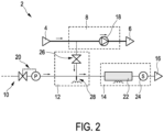
Fig. 2 , the configurations of thesampling device 8, theconversion device 12, and thegas sensor 14 are detailed. Thesampling device 8 comprises afluid pump 18 for pumping the sampling fluid from thefluid sampling inlet 4 to thefluid sampling outlet 6 and towards theconversion device 12. Theconversion device 12 comprises a droplet dispenser that is fluidically connected to thesampling device 8. Thedroplet dispenser 26 generates droplets of the sample liquid that are dispensed to apyrolysis well 28. The pyrolysis well 28 is heated to convert the sample droplets into volatile markers that are carried to thegas sensor 14. Thegas sensor 14 comprises achromatographic column 22 and adetector 24 connected to thechromatographic column 22. - The gas comprising the volatile markers that is generated in the pyrolysis well 28 is provided to the chromatographic column along with carrier gas supplied by the
carrier gas source 10. Thedetector 24 records the output of thechromatographic column 22 as a function of time to establish a chromatogram. To improve a selectivity, different temperatures may be used at the pyrolysis well 28 and the measurement process may be conducted repeatedly for different temperatures. It is preferred that thecarrier gas source 10 does not contain oxygen to avoid complete conversion to CO2. The pyrolysis well 28 may comprise a wall that can be heated rapidly, wherein the heating may be conducted by means of an RF coil or resistively. Within thedroplet dispenser 26, the droplets can be transported by pressure, for example using the piezo-effect, gravity or electrowetting. In the presented embodiment, the pyrolysis well 28 includes the widely used split/splitless injection of liquids, heated in the well above their boiling points. For the pyrolysis, the temperature can be lower than the boiling point, since the rapid heating in absence of oxygen breaks molecules into volatile fragments. -
Fig. 3 shows an alternative embodiment of agas chromatography instrument 2. Compared to the embodiment ofFig. 2 ,Fig. 3 proposes an alternative design of thegas sensor 14. Thegas sensor 14 ofFig. 3 only comprises adetector 24. Thedetector 24 is preferably composed of multiple non-identical sensors, for instance, an array of sensors composed of different sensor materials and/or operating conditions. Thereby, the selectivity of theinstrument 2 is improved. The individual sensors may detect gases based on known techniques like chemoresistive, electro-chemical and optical absorption. All in all, compared to the embodiment ofFig. 2 , the measurement speed may be improved with the configuration ofFig. 3 . -
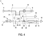
Fig. 4 shows yet another alternative embodiment of agas chromatography instrument 2. In this embodiment, theconversion device 12 comprises a liquid-to-gas-converter 30 that is configured to convert liquid sampled by thesampling device 8 into gas. The liquid-to-gas-converter 30 is configured as a pyrolysis well 28 connected to avalve arrangement 31 that is configured as a six-port-valve 32. Thevalve arrangement 31 may be switched to a feeding mode in which thesampling device 8 is fluidically connected to the liquid-to-gas-converter 30 to fill the liquid-to-gas-converter 30 with the liquid sample, and a flushing mode in which acarrier gas source 10 is fluidically connected to the liquid-to-gas-converter 30 for flushing excess fluid using carrier gas and an analysis mode in which the liquid-to-gas-converter 30 is fluidically connected to thegas sensor 14. Switching between the mentioned modes is conducted by means of the six-port-valve 32. Theconversion device 12 furthermore comprises avalve 34 arranged between the six-port-valve 32 and thegas sensor 14. Thevalve 34 comprises threeports first port 36 is connected to the six-port-valve 32. Thesecond port 38 is connected to thegas sensor 14 and thethird port 40 is connected to anoutlet 42. Similar to the embodiment ofFig. 2 , thegas sensor 14 comprises thechromatographic column 22 and thedetector 24. - During feeding mode operation, the pyrolysis well 28 is filled with the sample liquid, when the six-port-
valve 32 is in the dotted position. Afterwards, in the flushing mode, the excess fluid is flushed dry using carrier gas provided by thecarrier gas source 10 and vented via theoutlet 42. Therefore, the six-port-valve 32 is switched into the position illustrated with the dashed black line. Afterwards, in the analysis mode, the pyrolysis well 28 is heated. The resulting volatile pyrolysis products are transported with the help of the carrier gas to thegas sensor 14. Optionally, a surface area next to the pyrolysis well 28 is covered with hydrophobic coating to facilitate the flushing step. This embodiment has been found to be robust, since the possible non-volatile ashes remaining in the pyrolysis well 28 are flushed away in the next sampling phase. - In the embodiment of
Fig. 5 , theconversion device 12 and thegas sensor 14 are equal to the embodiment ofFig. 2 . Thesampling device 8 configuration however differs. In the embodiment ofFig. 5 , thesampling device 8 comprises thefluid pump 18 pumping sampling fluid from thefluid sampling inlet 4 to aliquid filter 44. Theliquid filter 44 provides aretentate stream 46 and apermeate stream 48. Thepermeate stream 48 is connected to theconversion device 12, in particular, to thedroplet dispenser 26. In this embodiment, the advantage of a higher selectivity notably for a sample liquid containing mixtures of markers are achieved by means of theliquid filter 44. - In the embodiment of
Fig. 6 , amembrane 54 is utilized to outgas volatile compounds from a liquid sample provided by thesampling device 8. This is also called pervaporation. Thevalves membrane 54 to up-concentrate volatile compounds (in the dashed black position) and collectively inject them into thechromatographic column 22 of thegas sensor 14. As carrier gas, ambient air is provided by anambient air inlet 56. The ambient air is filtered by aVOC filter 58 before reaching themembrane 54. Thepressure controller 20 is arranged downstream of thegas sensor 14. With the help of apump 60, the carrier gas comprising the volatile markers is guided towards agas outlet 16. The use of ambient air filtered by aVOC filter 58 is beneficial compared to the use of carrier gas from a pressurized cylinder, because this embodiment allows to have, in particular extra, underpressure below themembrane 54. Optionally, the liquid provided by thesampling device 8 above themembrane 54 is heated to enhance the outgassing rate, allowing detection of less volatile compounds. All in all, the embodiment shown inFig. 6 is simpler and ambient air may be used as carrier gas. -
Fig. 7 shows an alternative embodiment also utilizing amembrane 54. Compared to the embodiment ofFig. 6 , thegas sensor 14 only comprises adetector 24. By removing the chromatographic column 22 (seeFig. 6 ) from thegas sensor 14, it is also possible to remove thevalves membrane 54. It is preferred for enhanced selectivity to use an array ofnon-identical detectors 24, for instance an array of chemoresistive or electro-chemical sensors composed of different sensor materials and/or operating conditions. This allows for additional selectivity and compensates for the removal of thechromatographic column 22 compared to the embodiment ofFig. 6 . -
Fig. 8 shows yet another alternative embodiment of agas chromatography instrument 2 that is similar to the embodiment ofFig. 4 . As a difference, however, the pyrolysis well 28 is replaced by a solid-phase microextraction device (SPME) 62. Thedevice 2 according to the embodiment ofFig. 8 is operated as follows: - Solid-phase microextraction (SPME) sorbents are used to extract analytes from the sampled liquid when the six-port-
valve 32 is switched to the dotted position. Afterwards, the SPME 62 sorbents are flushed dry using carrier gas in the dashed position of the six-port-valve 32. Excess fluid is vented via theoutlet 42. After the SPME 62 is flushed dry, it is heated and resulting desorbed VOCs are transported to and analyzed by thegas sensor 14. The SPME 62 may be heated gradually or stepwise to achieve desorption of selective volatile species to facilitate selective detection. The embodiment ofFig. 8 is beneficial, because ambient air may be used as carrier gas and analyzed or up-concentrated during SPME sampling, resulting in high sensitivity of detection. -
Fig. 9 shows an embodiment of amethod 100 for autonomously determining a concentration of a volatile marker in a liquid sample using gas chromatography. Themethod 100 comprises the steps of autonomously providing 102 a sample fluid to be analyzed, autonomously converting 104 at least part of the sample fluid into a gas sample, and autonomously determining 106 a marker concentration in the gas sample. - Other variations to the disclosed embodiments can be understood and effected by those skilled in the art in practicing the claimed invention, from a study of the drawings, the disclosure, and the appended claims.
- In the claims, the word "comprising" does not exclude other elements or steps, and the indefinite article "a" or "an" does not exclude a plurality.
- A single unit or device may fulfill the functions of several items recited in the claims. The mere fact that certain measures are recited in mutually different dependent claims does not indicate that a combination of these measures cannot be used to advantage.
- A computer program may be stored/distributed on a suitable medium, such as an optical storage medium or a solid-state medium, supplied together with or as part of other hardware, but may also be distributed in other forms, such as via the Internet or other wired or wireless telecommunication systems.
- Any reference signs in the claims should not be construed as limiting the scope.
- The invention relates to a gas chromatography instrument for autonomously determining a concentration of a volatile marker in a liquid sample. The instrument comprises a sampling device configured for autonomously sampling a liquid to be analyzed, a gas sensor, and a conversion device connected to the sampling device and the gas sensor. By utilizing a conversion device that is configured to autonomously convert the sampled liquid into a gas to be analyzed by the gas sensor, an automated continuous monitoring of relevant markers in liquid samples is achieved.
Claims (15)
- Gas chromatography instrument (2) for autonomously determining a concentration of a volatile marker in a liquid sample, the instrument (2) comprising:- a sampling device (8) configured for autonomously sampling a liquid to be analyzed,- a gas sensor (14), and- a conversion device (12) connected to the sampling device (8) and the gas sensor (14),wherein the conversion device (12) is configured to autonomously convert the sampled liquid into a gas to be analyzed by the gas sensor (14).
- The gas chromatography instrument (2) as defined by claim 1, wherein the sampling device (8) is connected to a fluid sampling inlet (4) and to a fluid sampling outlet (6), and wherein fluid to be analyzed is provided by the fluid sampling inlet (4) continuously or semi-continuously.
- The gas chromatography instrument (2) as defined by any of claims 1 or 2, wherein the gas sensor (14) comprises a chromatographic column (22) connected to a detector (24).
- The gas chromatography instrument (2) as defined by any of the preceding claims, wherein the gas sensor (14) comprises a detector (24), and wherein the detector comprises multiple non-identical sensors.
- The gas chromatography instrument (2) as defined by claim 4, wherein the multiple non-identical sensors comprise different sensor materials and/or operating conditions.
- The gas chromatography instrument (2) as defined by any of the preceding claims, wherein the conversion device (12) comprises a droplet dispenser (26) connected to the sampling device (8), and a pyrolysis well (28) that is configured to convert droplets provided by the droplet dispenser (26) into gas, in particular by means of heating.
- The gas chromatography instrument (2) as defined by any of the preceding claims, wherein the sampling device (8) comprises a liquid filter (44) connected to the fluid sampling inlet (4), wherein the liquid filter (44) provides a retentate stream (46) and a permeate stream (48), and wherein either of the retentate stream (46) or the permeate stream (48) is connected to the conversion device (12)
- The gas chromatography instrument (2) as defined by any of claims 1 to 5, wherein the conversion device (12) comprises a liquid-to-gas-converter (30) that is configured to convert liquid sampled by the sampling device (8) into gas, and a valve arrangement (31), wherein the valve arrangement (31) is configured to provide the following modes of operation:- a feeding mode in which the sampling device (8) is fluidically connected to the liquid-to-gas-converter (30) to fill the liquid-to-gas-converter (30) with the liquid sample,- a flushing mode in which a carrier gas source (10) is fluidically connected to the liquid-to-gas-converter (30) for flushing excess fluid using carrier gas, and- an analysis mode in which the liquid-to-gas-converter (30) is fluidically connected to the gas sensor (14).
- The gas chromatography instrument (2) as defined by claim 8, wherein the liquid-to-gas-converter (30) is configured as a pyrolysis well (28) or a solid-phase microextraction device (SPME) (62).
- The gas chromatography instrument (2) as defined by claim 8 or 9, wherein the conversion device (12) comprises a six-port-valve (32) connected to the sampling device (8), the carrier gas source (10) and the gas sensor (14).
- The gas chromatography instrument (2) as defined by claim 8,9 or 10, further comprising a valve (34) arranged between the liquid-to-gas-converter (30) and the gas sensor (14), wherein the valve (34) comprises at least three ports (36, 38, 40), and wherein a first port (36) is connected to the liquid-to-gas-converter (30), a second port (38) is connected to the gas sensor (14) and a third port (40) is connected to an outlet (42).
- The gas chromatography instrument (2) as defined by any of claim 1 to 5, wherein the conversion device (12) comprises a membrane (54) connected to the sampling device (8) and the gas sensor (14), wherein the membrane (54) is configured to outgas volatile compounds from the liquid sample.
- The gas chromatography instrument (2) as defined by any of the preceding claims, comprising a processor, wherein the processor is configured to carry out the steps of the method (100) as defined in claim 14.
- A method (100) for autonomously determining a concentration of a volatile marker in a liquid sample using gas chromatography, the method (100) comprising:- autonomously providing (102) a sample fluid to be analyzed,- autonomously converting (104) at least part of the sample fluid into a gas sample, and- autonomously determining (106) a marker concentration in the gas sample.
- A computer program for autonomously determining a concentration of a marker in a sample, the computer program comprising program code means for causing an instrument (2) as defined in any of claims 1 to 13 to carry out the steps of the method (100) as defined in claim 14, when the computer program is run on a computer controlling the instrument (2).
Priority Applications (3)
| Application Number | Priority Date | Filing Date | Title |
|---|---|---|---|
| EP21204430.9A EP4170340A1 (en) | 2021-10-25 | 2021-10-25 | Gas chromatography instrument for autonomously determining a concentration of a volatile marker in a liquid sample |
| PCT/EP2022/078774 WO2023072646A1 (en) | 2021-10-25 | 2022-10-17 | Gas chromatography instrument for autonomously determining a concentration of a volatile marker in a liquid sample |
| TW111140274A TW202334647A (en) | 2021-10-25 | 2022-10-24 | Gas chromatography instrument for autonomously determining a concentration of a volatile marker in a liquid sample |
Applications Claiming Priority (1)
| Application Number | Priority Date | Filing Date | Title |
|---|---|---|---|
| EP21204430.9A EP4170340A1 (en) | 2021-10-25 | 2021-10-25 | Gas chromatography instrument for autonomously determining a concentration of a volatile marker in a liquid sample |
Publications (1)
| Publication Number | Publication Date |
|---|---|
| EP4170340A1 true EP4170340A1 (en) | 2023-04-26 |
Family
ID=78598733
Family Applications (1)
| Application Number | Title | Priority Date | Filing Date |
|---|---|---|---|
| EP21204430.9A Withdrawn EP4170340A1 (en) | 2021-10-25 | 2021-10-25 | Gas chromatography instrument for autonomously determining a concentration of a volatile marker in a liquid sample |
Country Status (3)
| Country | Link |
|---|---|
| EP (1) | EP4170340A1 (en) |
| TW (1) | TW202334647A (en) |
| WO (1) | WO2023072646A1 (en) |
Citations (4)
| Publication number | Priority date | Publication date | Assignee | Title |
|---|---|---|---|---|
| WO2006121590A1 (en) * | 2005-05-10 | 2006-11-16 | University Of Florida Research Foundation, Inc. | Detection and measurement of hematological parameters characterizing cellular blood components |
| WO2015052721A1 (en) * | 2013-10-09 | 2015-04-16 | Spectrosense Ltd. | Modified data representation in gas chromatographic analysis |
| EP2924429A1 (en) | 2014-03-26 | 2015-09-30 | Frontier Laboratories Ltd. | Gas phase component analyzer |
| US9435772B2 (en) | 2013-05-02 | 2016-09-06 | Japan Analytical Industry Co., Ltd. | Heating apparatus for a gas chromatograph, and heating method for a gas chromatograph |
-
2021
- 2021-10-25 EP EP21204430.9A patent/EP4170340A1/en not_active Withdrawn
-
2022
- 2022-10-17 WO PCT/EP2022/078774 patent/WO2023072646A1/en unknown
- 2022-10-24 TW TW111140274A patent/TW202334647A/en unknown
Patent Citations (4)
| Publication number | Priority date | Publication date | Assignee | Title |
|---|---|---|---|---|
| WO2006121590A1 (en) * | 2005-05-10 | 2006-11-16 | University Of Florida Research Foundation, Inc. | Detection and measurement of hematological parameters characterizing cellular blood components |
| US9435772B2 (en) | 2013-05-02 | 2016-09-06 | Japan Analytical Industry Co., Ltd. | Heating apparatus for a gas chromatograph, and heating method for a gas chromatograph |
| WO2015052721A1 (en) * | 2013-10-09 | 2015-04-16 | Spectrosense Ltd. | Modified data representation in gas chromatographic analysis |
| EP2924429A1 (en) | 2014-03-26 | 2015-09-30 | Frontier Laboratories Ltd. | Gas phase component analyzer |
Non-Patent Citations (2)
| Title |
|---|
| CORDERO CHIARA ET AL: "Potential of the reversed-inject differential flow modulator for comprehensive two-dimensional gas chromatography in the quantitative profiling and fingerprinting of essential oils of different complexity", JOURNAL OF CHROMATOGRAPHY A, ELSEVIER, AMSTERDAM, NL, vol. 1417, 11 September 2015 (2015-09-11), pages 79 - 95, XP029287016, ISSN: 0021-9673, DOI: 10.1016/J.CHROMA.2015.09.027 * |
| GIUSEPPE LUBES ET AL: "Analysis of Volatile Compounds by Advanced Analytical Techniques and Multivariate Chemometrics", CHEMICAL REVIEWS, vol. 117, no. 9, 17 March 2017 (2017-03-17), US, pages 6399 - 6422, XP055475385, ISSN: 0009-2665, DOI: 10.1021/acs.chemrev.6b00698 * |
Also Published As
| Publication number | Publication date |
|---|---|
| WO2023072646A1 (en) | 2023-05-04 |
| TW202334647A (en) | 2023-09-01 |
Similar Documents
| Publication | Publication Date | Title |
|---|---|---|
| US11796515B2 (en) | Gas analyte spectrum sharpening and separation with multi-dimensional micro-GC for gas chromatography analysis | |
| JP4903056B2 (en) | Gas chromatograph | |
| US8247239B2 (en) | System for introducing standard gas into sample container | |
| US20230012349A1 (en) | Anomaly detection and diagnosis in chromatography applications | |
| JP7072134B2 (en) | Sample pre-concentration system and method for use in gas chromatography | |
| WO2009073269A1 (en) | Chromatography using multiple detectors | |
| TWI642936B (en) | Apparatus and method for analyzing breath gas mixture for halitosis detection | |
| WO2007094242A1 (en) | Degasifier and liquid chromatograph equipped therewith | |
| JP2009257839A (en) | Rapid analyzing system of voc and analyzing method of voc | |
| US5922106A (en) | Automated gas chromatography | |
| JP2006337158A (en) | Sample concentration device | |
| KR101744462B1 (en) | System for analysing gas | |
| JP2009236539A (en) | Device and method for concentrating and detecting selectively composite gaseous chemical substance | |
| JP2009180618A (en) | Pretreatment apparatus and liquid chromatograph device | |
| EP4170340A1 (en) | Gas chromatography instrument for autonomously determining a concentration of a volatile marker in a liquid sample | |
| US7028562B2 (en) | Vacuum membrane extraction system | |
| US20170356886A1 (en) | Device for taking and analyzing a gaseous sample | |
| KR101109644B1 (en) | water analysis system | |
| EP3563147A1 (en) | Gas detection apparatus comprising a gas chromatography column | |
| Kunert et al. | Volatile sampling from biological sources by the closed-loop-stripping technique | |
| JP3988675B2 (en) | Odor measuring device | |
| CN216669856U (en) | Cancer detection system based on miniature gas chromatography | |
| KR100782207B1 (en) | Sample preprocessing method and preprocessing device using it | |
| JP3114926U (en) | Flow controller and sample concentrator using the same | |
| JPH11242020A (en) | Atmospheric analyzer |
Legal Events
| Date | Code | Title | Description |
|---|---|---|---|
| PUAI | Public reference made under article 153(3) epc to a published international application that has entered the european phase |
Free format text: ORIGINAL CODE: 0009012 |
|
| STAA | Information on the status of an ep patent application or granted ep patent |
Free format text: STATUS: THE APPLICATION HAS BEEN PUBLISHED |
|
| AK | Designated contracting states |
Kind code of ref document: A1 Designated state(s): AL AT BE BG CH CY CZ DE DK EE ES FI FR GB GR HR HU IE IS IT LI LT LU LV MC MK MT NL NO PL PT RO RS SE SI SK SM TR |
|
| STAA | Information on the status of an ep patent application or granted ep patent |
Free format text: STATUS: THE APPLICATION IS DEEMED TO BE WITHDRAWN |
|
| 18D | Application deemed to be withdrawn |
Effective date: 20231027 |