EP4169842A2 - Package - Google Patents
Package Download PDFInfo
- Publication number
- EP4169842A2 EP4169842A2 EP22202700.5A EP22202700A EP4169842A2 EP 4169842 A2 EP4169842 A2 EP 4169842A2 EP 22202700 A EP22202700 A EP 22202700A EP 4169842 A2 EP4169842 A2 EP 4169842A2
- Authority
- EP
- European Patent Office
- Prior art keywords
- perimeter
- iii
- folding
- upper wall
- vii
- Prior art date
- Legal status (The legal status is an assumption and is not a legal conclusion. Google has not performed a legal analysis and makes no representation as to the accuracy of the status listed.)
- Withdrawn
Links
- 238000007789 sealing Methods 0.000 claims description 31
- 230000005484 gravity Effects 0.000 claims description 7
- 238000004891 communication Methods 0.000 claims description 5
- 239000012530 fluid Substances 0.000 claims description 5
- 239000000047 product Substances 0.000 description 19
- 230000015572 biosynthetic process Effects 0.000 description 5
- 238000000034 method Methods 0.000 description 5
- 239000000463 material Substances 0.000 description 4
- 230000001788 irregular Effects 0.000 description 3
- 238000009825 accumulation Methods 0.000 description 2
- 230000009969 flowable effect Effects 0.000 description 2
- 239000012263 liquid product Substances 0.000 description 2
- 238000004806 packaging method and process Methods 0.000 description 2
- 230000008569 process Effects 0.000 description 2
- 239000007787 solid Substances 0.000 description 2
- 239000004698 Polyethylene Substances 0.000 description 1
- XAGFODPZIPBFFR-UHFFFAOYSA-N aluminium Chemical compound [Al] XAGFODPZIPBFFR-UHFFFAOYSA-N 0.000 description 1
- 229910052782 aluminium Inorganic materials 0.000 description 1
- 230000004888 barrier function Effects 0.000 description 1
- 239000011111 cardboard Substances 0.000 description 1
- 239000003795 chemical substances by application Substances 0.000 description 1
- 238000010276 construction Methods 0.000 description 1
- 238000011109 contamination Methods 0.000 description 1
- 238000009792 diffusion process Methods 0.000 description 1
- 230000014509 gene expression Effects 0.000 description 1
- 230000006872 improvement Effects 0.000 description 1
- 238000009413 insulation Methods 0.000 description 1
- 239000011087 paperboard Substances 0.000 description 1
- 230000002093 peripheral effect Effects 0.000 description 1
- 239000004033 plastic Substances 0.000 description 1
- 229920003023 plastic Polymers 0.000 description 1
- -1 polyethylene Polymers 0.000 description 1
- 229920000573 polyethylene Polymers 0.000 description 1
- 239000011265 semifinished product Substances 0.000 description 1
- 238000007493 shaping process Methods 0.000 description 1
- 239000002699 waste material Substances 0.000 description 1
Images


Classifications
-
- B—PERFORMING OPERATIONS; TRANSPORTING
- B65—CONVEYING; PACKING; STORING; HANDLING THIN OR FILAMENTARY MATERIAL
- B65D—CONTAINERS FOR STORAGE OR TRANSPORT OF ARTICLES OR MATERIALS, e.g. BAGS, BARRELS, BOTTLES, BOXES, CANS, CARTONS, CRATES, DRUMS, JARS, TANKS, HOPPERS, FORWARDING CONTAINERS; ACCESSORIES, CLOSURES, OR FITTINGS THEREFOR; PACKAGING ELEMENTS; PACKAGES
- B65D5/00—Rigid or semi-rigid containers of polygonal cross-section, e.g. boxes, cartons or trays, formed by folding or erecting one or more blanks made of paper
- B65D5/02—Rigid or semi-rigid containers of polygonal cross-section, e.g. boxes, cartons or trays, formed by folding or erecting one or more blanks made of paper by folding or erecting a single blank to form a tubular body with or without subsequent folding operations, or the addition of separate elements, to close the ends of the body
- B65D5/029—Rigid or semi-rigid containers of polygonal cross-section, e.g. boxes, cartons or trays, formed by folding or erecting one or more blanks made of paper by folding or erecting a single blank to form a tubular body with or without subsequent folding operations, or the addition of separate elements, to close the ends of the body the tubular body presenting a special shape
-
- B—PERFORMING OPERATIONS; TRANSPORTING
- B65—CONVEYING; PACKING; STORING; HANDLING THIN OR FILAMENTARY MATERIAL
- B65D—CONTAINERS FOR STORAGE OR TRANSPORT OF ARTICLES OR MATERIALS, e.g. BAGS, BARRELS, BOTTLES, BOXES, CANS, CARTONS, CRATES, DRUMS, JARS, TANKS, HOPPERS, FORWARDING CONTAINERS; ACCESSORIES, CLOSURES, OR FITTINGS THEREFOR; PACKAGING ELEMENTS; PACKAGES
- B65D21/00—Nestable, stackable or joinable containers; Containers of variable capacity
- B65D21/02—Containers specially shaped, or provided with fittings or attachments, to facilitate nesting, stacking, or joining together
- B65D21/0209—Containers specially shaped, or provided with fittings or attachments, to facilitate nesting, stacking, or joining together stackable or joined together one-upon-the-other in the upright or upside-down position
-
- B—PERFORMING OPERATIONS; TRANSPORTING
- B65—CONVEYING; PACKING; STORING; HANDLING THIN OR FILAMENTARY MATERIAL
- B65D—CONTAINERS FOR STORAGE OR TRANSPORT OF ARTICLES OR MATERIALS, e.g. BAGS, BARRELS, BOTTLES, BOXES, CANS, CARTONS, CRATES, DRUMS, JARS, TANKS, HOPPERS, FORWARDING CONTAINERS; ACCESSORIES, CLOSURES, OR FITTINGS THEREFOR; PACKAGING ELEMENTS; PACKAGES
- B65D5/00—Rigid or semi-rigid containers of polygonal cross-section, e.g. boxes, cartons or trays, formed by folding or erecting one or more blanks made of paper
- B65D5/02—Rigid or semi-rigid containers of polygonal cross-section, e.g. boxes, cartons or trays, formed by folding or erecting one or more blanks made of paper by folding or erecting a single blank to form a tubular body with or without subsequent folding operations, or the addition of separate elements, to close the ends of the body
- B65D5/06—Rigid or semi-rigid containers of polygonal cross-section, e.g. boxes, cartons or trays, formed by folding or erecting one or more blanks made of paper by folding or erecting a single blank to form a tubular body with or without subsequent folding operations, or the addition of separate elements, to close the ends of the body with end-closing or contents-supporting elements formed by folding inwardly a wall extending from, and continuously around, an end of the tubular body
- B65D5/064—Rectangular containers having a body with gusset-flaps folded outwardly or adhered to the side or the top of the container
-
- B—PERFORMING OPERATIONS; TRANSPORTING
- B65—CONVEYING; PACKING; STORING; HANDLING THIN OR FILAMENTARY MATERIAL
- B65D—CONTAINERS FOR STORAGE OR TRANSPORT OF ARTICLES OR MATERIALS, e.g. BAGS, BARRELS, BOTTLES, BOXES, CANS, CARTONS, CRATES, DRUMS, JARS, TANKS, HOPPERS, FORWARDING CONTAINERS; ACCESSORIES, CLOSURES, OR FITTINGS THEREFOR; PACKAGING ELEMENTS; PACKAGES
- B65D5/00—Rigid or semi-rigid containers of polygonal cross-section, e.g. boxes, cartons or trays, formed by folding or erecting one or more blanks made of paper
- B65D5/42—Details of containers or of foldable or erectable container blanks
- B65D5/72—Contents-dispensing means
- B65D5/74—Spouts
- B65D5/746—Spouts formed separately from the container
-
- B—PERFORMING OPERATIONS; TRANSPORTING
- B65—CONVEYING; PACKING; STORING; HANDLING THIN OR FILAMENTARY MATERIAL
- B65D—CONTAINERS FOR STORAGE OR TRANSPORT OF ARTICLES OR MATERIALS, e.g. BAGS, BARRELS, BOTTLES, BOXES, CANS, CARTONS, CRATES, DRUMS, JARS, TANKS, HOPPERS, FORWARDING CONTAINERS; ACCESSORIES, CLOSURES, OR FITTINGS THEREFOR; PACKAGING ELEMENTS; PACKAGES
- B65D81/00—Containers, packaging elements, or packages, for contents presenting particular transport or storage problems, or adapted to be used for non-packaging purposes after removal of contents
- B65D81/36—Containers, packaging elements, or packages, for contents presenting particular transport or storage problems, or adapted to be used for non-packaging purposes after removal of contents adapted to be used for non-packaging purposes after removal of contents
- B65D81/365—Containers, or parts thereof, simulating or being incorporated into other items, e.g. puppet, animal, vehicle, building, dumb bells
- B65D81/366—Containers, or parts thereof, simulating or being incorporated into other items, e.g. puppet, animal, vehicle, building, dumb bells the container closure only being provided with a three dimensional figure, e.g. chess piece, animal
-
- B—PERFORMING OPERATIONS; TRANSPORTING
- B65—CONVEYING; PACKING; STORING; HANDLING THIN OR FILAMENTARY MATERIAL
- B65D—CONTAINERS FOR STORAGE OR TRANSPORT OF ARTICLES OR MATERIALS, e.g. BAGS, BARRELS, BOTTLES, BOXES, CANS, CARTONS, CRATES, DRUMS, JARS, TANKS, HOPPERS, FORWARDING CONTAINERS; ACCESSORIES, CLOSURES, OR FITTINGS THEREFOR; PACKAGING ELEMENTS; PACKAGES
- B65D2251/00—Details relating to container closures
- B65D2251/02—Grip means
-
- B—PERFORMING OPERATIONS; TRANSPORTING
- B65—CONVEYING; PACKING; STORING; HANDLING THIN OR FILAMENTARY MATERIAL
- B65D—CONTAINERS FOR STORAGE OR TRANSPORT OF ARTICLES OR MATERIALS, e.g. BAGS, BARRELS, BOTTLES, BOXES, CANS, CARTONS, CRATES, DRUMS, JARS, TANKS, HOPPERS, FORWARDING CONTAINERS; ACCESSORIES, CLOSURES, OR FITTINGS THEREFOR; PACKAGING ELEMENTS; PACKAGES
- B65D2251/00—Details relating to container closures
- B65D2251/06—Special configurations; Closures simulating or provided with another item, e.g. puppet, animal, vehicle, building
-
- B—PERFORMING OPERATIONS; TRANSPORTING
- B65—CONVEYING; PACKING; STORING; HANDLING THIN OR FILAMENTARY MATERIAL
- B65D—CONTAINERS FOR STORAGE OR TRANSPORT OF ARTICLES OR MATERIALS, e.g. BAGS, BARRELS, BOTTLES, BOXES, CANS, CARTONS, CRATES, DRUMS, JARS, TANKS, HOPPERS, FORWARDING CONTAINERS; ACCESSORIES, CLOSURES, OR FITTINGS THEREFOR; PACKAGING ELEMENTS; PACKAGES
- B65D5/00—Rigid or semi-rigid containers of polygonal cross-section, e.g. boxes, cartons or trays, formed by folding or erecting one or more blanks made of paper
- B65D5/42—Details of containers or of foldable or erectable container blanks
- B65D5/4266—Folding lines, score lines, crease lines
-
- B—PERFORMING OPERATIONS; TRANSPORTING
- B65—CONVEYING; PACKING; STORING; HANDLING THIN OR FILAMENTARY MATERIAL
- B65D—CONTAINERS FOR STORAGE OR TRANSPORT OF ARTICLES OR MATERIALS, e.g. BAGS, BARRELS, BOTTLES, BOXES, CANS, CARTONS, CRATES, DRUMS, JARS, TANKS, HOPPERS, FORWARDING CONTAINERS; ACCESSORIES, CLOSURES, OR FITTINGS THEREFOR; PACKAGING ELEMENTS; PACKAGES
- B65D85/00—Containers, packaging elements or packages, specially adapted for particular articles or materials
- B65D85/70—Containers, packaging elements or packages, specially adapted for particular articles or materials for materials not otherwise provided for
- B65D85/72—Containers, packaging elements or packages, specially adapted for particular articles or materials for materials not otherwise provided for for edible or potable liquids, semiliquids, or plastic or pasty materials
Definitions
- the present invention relates to a package, in particular, for the packaging of liquid products or, in any case, flowable products such as, for example, granular products.
- the package described here is of the type comprising a container formed by a folded and sealed sheet.
- Packages of this type are commonly made by means of a process that envisages at least partial shaping of the container, starting from a sheet unwound from a reel, and a concomitant filling of the container being formed, with the product to be packaged.
- packages of the type in question have a prismatic shape with a square or rectangular base.
- Packages with alternative shapes have also been proposed, for example, tetrahedral, pouch, pyramidal, etc., which, however, have so far had little diffusion.
- a wall is said to be “inclined” with respect to another wall when it is substantially not parallel to that other wall.
- a vertex of the perimeter of the so-called “inclined” wall is located at a shorter distance than the distance at which the other vertices of the same perimeter are located.
- These other vertices may be at the same distance, or at different distances from the other wall.
- an inclined wall has an inclination between 3° and 30°, preferably between 23° and 25°, in particular, equal to 23.5°, with respect to another wall.
- triangular shape includes both a geometric triangular shape and relative approximations wherein, for example, the vertices of the triangle are beveled, or wherein the sides of the triangle are slightly concave or convex.
- the packages of the prior art may not be very functional for the user, for example, during the step of pouring the contents, both because the package may deform, in particular, when the package is full and subject to the internal pressure of the contents, or when it is grasped with a certain force by the user, and because the total emptying of the package may require an overturning, or rather, a rotation of 180°, and a deformation of the package in order to dispense the contents outside. In these cases, most of the time there is an irregular dispensing that is not easy for the user to control.
- the Applicant has, therefore, perceived that the irregular dispensing that is not easy to control for the user of the package could be improved, and even avoided, by appropriately modifying the structure of the package.
- the Applicant has, therefore, found that a triangular-shaped package with an upper side having an appropriate inclination with respect to the lower side allows the entire contents to flow towards a vertex of the package, without the package losing its original shape, so as to facilitate the regular and controlled dispensing of the content itself.
- the Applicant has found that with such a container, in the face of an appropriate rotation of the container by just over 90°, and which requires a minimum effort on the part of the user, all the contents that are inside the container may be easily conveyed towards a specific area of the package at which the dispensing opening can be provided, so that the user can control and regulate the dispensing of all the contents and, therefore, completely empty the package.
- the present invention proposes a package of the type indicated at the beginning, which has a new shape and allows a series of advantages to be obtained, as will be described in detail below.
- the present invention relates to a package comprising a container formed by a folded and sealed sheet.
- the container preferably includes an upper wall delimited by a first triangular-shaped perimeter.
- the container preferably includes side walls.
- the container preferably includes a lower wall opposite the upper wall and delimited by a second triangular-shaped perimeter, said upper wall being preferably inclined with respect to the lower wall.
- Such a container has a relatively rigid structure, which is able to maintain its original shape over time, regardless of the stresses that the package may undergo during the various stages of storage, transport, etc. Thanks to the new shape of the container, the user's grip of the package is also easier.
- the container comprises:
- An opening is preferably made on the upper wall of the container.
- the package comprises a closing device fixed onto the upper wall at the opening.
- the closing device comprises a base.
- the base comprises an inlet, an outlet and a tubular portion that connects the inlet to the outlet.
- said base is fixed to the container at the opening of the upper wall, preferably, in a condition wherein the inlet faces towards the opening of the upper wall.
- the closing device comprises a cap.
- the cap is mounted on the tubular portion of the base.
- the cap is rotatably mounted, around a reference axis.
- the cap closes the outlet of the base, to prevent fluid communication between the inside of the container and the outside.
- the closing device includes a top region.
- the cap includes a top region.
- the top region is such as to define at least two points on the same upper plane, which also contains one side of the first perimeter.
- said upper plane is parallel or substantially parallel to said lower wall.
- Such a solution allows a package to be obtained with its own well-defined virtual support surface, on which to place in a solid and reliable way, for example, another package according to the present invention having its own virtual support surface, and so on, thus determining a particularly stable stack.
- the container comprises:
- An opening is preferably made on the upper wall of the container.
- the package comprises a closing device fixed on the upper wall, preferably at the opening.
- the closing device comprises a base.
- the base comprises an inlet, an outlet and a tubular portion that connects the inlet to the outlet.
- said base is fixed to the container at the opening of the upper wall, preferably, in a condition wherein the inlet faces towards the opening of the upper wall.
- the cap comprises a gripping portion.
- the gripping portion projects radially from the tubular portion of the base.
- the gripping portion has a non-circular perimeter profile.
- the gripping portion is kept within the side dimensions of the first perimeter, preferably in a predetermined closing position of the cap.
- the gripping portion extends on a plane perpendicular to the reference axis to cover at least 50% of a triangular area delimited by the first perimeter at the top.
- the present invention relates to a sheet for producing a container of the type comprising:
- the present invention may comprise one or more of the following characteristics.
- the side walls may include:
- a difference in length between major base and minor base of the fourth trapezoidal perimeter or of the fifth trapezoidal perimeter is preferably less than or equal to 40% of a height of the first triangular perimeter defined relative to one side of the first triangular perimeter in common with the third rectangular perimeter.
- the first perimeter defines an isosceles triangle and the second perimeter defines an equilateral triangle, or vice versa.
- an opening is made on the upper wall of the container.
- said opening of the upper wall is closed by a tear-off or removable film.
- said first triangular perimeter and said opening of the upper wall have a respective center of gravity; preferably the center of gravity of the opening is in a position displaced from the center of gravity of the first perimeter, more preferably towards a vertex of the first perimeter. Preferably, this vertex of the first perimeter is located at a shorter distance from the lower wall than the other vertices of the first perimeter.
- the opening of the upper wall is centered on an axis of symmetry of a triangular area delimited by the first perimeter.
- the particular positioning of the opening on the upper wall favors the generation of a stable and constant flow of product through the same opening.
- the convergence of the container walls towards the opening which is determined by the triangular shape of the upper wall, prevents the formation of product accumulation areas near the opening, when the container is tilted to dispense the product.
- These areas are, instead, present in the solutions of the prior art, and are responsible for both an instability of the outgoing product flow, and a difficulty in completely emptying the container.
- the dispensing of the product from the container of the package described here is, therefore, significantly improved compared to the solutions of the prior art.
- the package may further comprise a closing device, preferably fixed on the upper wall at the opening.
- the closing device may comprise:
- the cap preferably includes a top region such as to define at least two points on the same upper plane, which also contains one side of the first perimeter. Said upper plane is preferably parallel or substantially parallel to said lower wall.
- said at least two points lie on the same line, in particular, substantially parallel to said side of the first perimeter.
- the cap comprises a gripping portion, which protrudes radially from the tubular portion of the base and extends, on a plane perpendicular to the reference axis, to cover at least 50% at the top of a delimited triangular area from the first perimeter, and preferably has a non-circular perimeter profile so as to remain within the side dimensions of the first perimeter, in a predetermined closing position of the cap.
- the first perimeter includes a first series of folding and/or sealing lines of the sheet connecting the upper wall to the side walls
- the second perimeter includes a second series of folding and/or sealing lines of the sheet that connect the lower wall to the side walls.
- the package described here is, in particular, intended for the packaging of liquid products or, in any case, flowable products such as, for example, granular products.
- the package described here - indicated overall with the reference number 1- comprises a container 2 having:
- the container 2 is made from a folded and sealed sheet 100.
- the sheet 100 may be of the conventional type.
- the sheets used to produce containers for applications of the type in question usually have a multilayer structure formed by the overlapping of layers of different materials with various functions such as, for example, structural, thermal insulation, protection from light, barrier function with respect to contamination by external agents, reciprocal connection of sheet layers, etc.
- the sheet 100 may, for example, have a multilayer structure formed by the overlapping of layers, respectively, of paper or cardboard, aluminum, and one or more plastic materials, preferably polyethylene. In any case, these aspects are beyond the innovative aspects of the solution described here and, therefore, will not be described here in further detail.
- the walls 4-8 of the container 2 are delimited by respective perimeters.
- each perimeter of the walls 4-8 includes folding and/or sealing lines of the sheet 100, which connect the respective wall to the adjacent walls of the container 2.
- the respective perimeters of the upper and lower walls 4, 5 are both triangular in shape. Furthermore, the upper wall 4 is inclined with respect to the lower wall 5, preferably so that a vertex A of the perimeter of the upper wall 4 is at a shorter distance from the lower wall 5, with respect to the other two vertices B, C of the same perimeter. The vertices B and C may be at the same distance or at different distances from the lower wall 5.
- the upper wall 4 is inclined with respect to the lower wall 5 at an angle between 3° and 30°, preferably between 23° and 25°, even more preferably at an angle of 23.5°.
- the perimeter of the upper wall 4 is formed by sides I, II, III, which define an isosceles triangle.
- the perimeter of the lower wall 5 is formed by sides IV, V, VI, which define an equilateral triangle.
- the perimeter of the upper wall 4 defines an equilateral triangle
- the perimeter of the lower wall 5 defines an isosceles triangle
- the perimeter of the side wall 6 is formed by sides I, IV, VII and IX.
- the perimeter of the side wall 7 is formed by sides II, V, VII and VIII.
- the perimeter of the side wall 8 is formed by sides III, VI, VIII and IX.
- the sides VII, VIII, IX are vertical.
- the container 2 comprises two flaps 11 - of which only one is visible in the figures -, which are connected to the upper wall 4, and are folded against the two side walls 6, 8.
- a flap 11 is folded around the folding line I, and is placed against the side wall 6, while the other flap 11 is folded around the folding line III and is placed against the side wall 8.
- an opening 4A closed by a tear-off or removable film is formed on the upper wall 4.
- the opening 4A is in a position displaced from the center of gravity of the triangular area of the upper wall 4 towards the vertex A, centered on an axis of symmetry K of the triangular area of the upper wall 4.
- the opening 4A defines an outlet through which to dispense the product contained in the container 2.
- the particular positioning of the opening 4A in the lower region of the upper wall 4 favors the generation of a stable and constant flow of product through the opening.
- the convergence of the walls 6 and 8 towards the opening 4A which is determined by the triangular shape of the wall 4, prevents the formation of product accumulation areas near the opening 4A, when the container 2 is tilted to dispense the product.
- These areas are, instead, present in the solutions of the prior art, and are responsible for both an instability of the outgoing flow of product, and a difficulty in completely emptying the container.
- the package 1 further comprises a closing device 20 fixed on the upper wall 4 at the opening 4A.
- the closing device 20 comprises:
- the cap 24 may be removable to open and close the outlet 22B, or, again for the same purpose, it can be movably mounted on the tubular portion 22C between two distinct positions wherein the outlet 22B is selectively opened or closed.
- the cap 24, is rotatably mounted, around a reference axis Y, on the tubular portion 22C.
- the base 22 is fixed to the upper wall 4 in a condition wherein the inlet 22A faces or engages the opening 4A of the same wall.
- the cap 24 includes a top region 24' such as to define at least two points P1, P2 on the same horizontal plane O, which also contains the side II.
- the two points P1 and P2 lie on the same horizontal line R, which is substantially parallel to the side II.
- the plane O is parallel to the lower wall 5.
- the two points P1, P2 and the side II identify an ideal support surface for a homologous package placed above the package 1.
- the cap 24 comprises a gripping portion 24A, intended to be grasped by the consumer for opening the package, which protrudes radially from the tubular portion 22C of the base 22, and generally has a planar conformation extending parallelly to the upper wall 4.
- the top region 24' is defined by a peripheral region of the gripping portion 24A, which is found precisely in the highest position of the package 1, when the cap 24 is in the closed condition.
- the gripping portion 24A has an extension such as to cover at least 50% of the triangular area of the upper wall 4 at the top. At the same time, the gripping portion 24A has a non-circular perimeter profile, such as to remain within the side dimensions of the upper wall 4, when the cap 24 is in the closed position.
- the cap 24 is able to perform a useful function in stacking the package 1 with other packages, and at the same time it may constitute a significant element in determining the overall aesthetic appearance of the package 1. Furthermore, the relevant dimensions of the cap 24 facilitate its grip by the user.
- the gripping portion 24A may have a plan profile - in the example shown a heart shape - such as to define a recess 24C designed to receive at least one finger of the user.
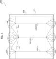
- Figure 5 illustrates an example of a sheet 100 for producing the container described above.
- the sheet 100 has a perimeter edge 101 of a predetermined shape, and predefined folding lines 102, to facilitate the folding of the sheet in a predetermined way, to form the container 2 illustrated in Figures 1-4 , during the relative forming process.
- the perimeter edge 101 and the formation of the folding lines 102 may vary according to the requirements of the specific applications and according to the forming method used.
- references 104 and 105 indicate the portions of the sheet 100 identified by the folding lines 102, which form the walls 4 and 5, respectively, in the folded condition of the sheet.
- the formation of the folding lines comprises three lines 102(1), 102(11), 102(111), parallel to each other, which, in the folded condition of the sheet, connect the side walls 6, 7 and 8 to each other.
- the folding line 102(11) is shorter than the other two folding lines 102(1), 102(111), so as to determine the inclined condition illustrated above of the upper wall 4 with respect to the lower wall 5.
- Figure 5 also illustrates a perimeter band 106, which represents the area along which the partially folded sheet 100 is sealed to obtain a semifinished product of the container 2, which is completely closed and contains the product inside, and which is then subjected to successive folding steps to form the container 2 in the final shape indicated above.
- this sealing area may determine, in the container 2, one or more sealing lines, which each define one side of one of the perimeters of the different walls of the container.
Landscapes
- Engineering & Computer Science (AREA)
- Mechanical Engineering (AREA)
- Cartons (AREA)
- Packaging Of Annular Or Rod-Shaped Articles, Wearing Apparel, Cassettes, Or The Like (AREA)
- Packages (AREA)
Abstract
Description
- The present invention relates to a package, in particular, for the packaging of liquid products or, in any case, flowable products such as, for example, granular products.
- The package described here is of the type comprising a container formed by a folded and sealed sheet.
- Packages of this type are commonly made by means of a process that envisages at least partial shaping of the container, starting from a sheet unwound from a reel, and a concomitant filling of the container being formed, with the product to be packaged.
- The most common packages of the type in question have a prismatic shape with a square or rectangular base. Packages with alternative shapes have also been proposed, for example, tetrahedral, pouch, pyramidal, etc., which, however, have so far had little diffusion.
- In the present description and in the claims attached thereto, some terms and expressions are deemed to have, unless otherwise explicitly indicated, the meaning expressed in the following definitions.
- A wall is said to be "inclined" with respect to another wall when it is substantially not parallel to that other wall. In particular, with reference to the other wall with respect to which the inclination condition is determined, a vertex of the perimeter of the so-called "inclined" wall is located at a shorter distance than the distance at which the other vertices of the same perimeter are located. These other vertices, in particular, may be at the same distance, or at different distances from the other wall. For example, an inclined wall has an inclination between 3° and 30°, preferably between 23° and 25°, in particular, equal to 23.5°, with respect to another wall.
- The term "triangular shape" includes both a geometric triangular shape and relative approximations wherein, for example, the vertices of the triangle are beveled, or wherein the sides of the triangle are slightly concave or convex.
- The Applicant has noted that the packages of the prior art may not be very functional for the user, for example, during the step of pouring the contents, both because the package may deform, in particular, when the package is full and subject to the internal pressure of the contents, or when it is grasped with a certain force by the user, and because the total emptying of the package may require an overturning, or rather, a rotation of 180°, and a deformation of the package in order to dispense the contents outside. In these cases, most of the time there is an irregular dispensing that is not easy for the user to control.
- The Applicant has observed that these drawbacks are generally due to the easily deformable structure of the package.
- The Applicant has also verified that these drawbacks are particularly accentuated in the case of packages with large formats. In particular, the Applicant has noted that, in this case, the walls of the package are liable to undergo greater deformations due to their larger dimensions, and to dispense a large quantity of product in an irregular and uncontrolled manner, with the consequent risk of unwanted waste.
- The Applicant has, therefore, perceived that the irregular dispensing that is not easy to control for the user of the package could be improved, and even avoided, by appropriately modifying the structure of the package.
- However, the Applicant has seen that providing a package with a solid and difficult to deform structure would not be sufficient for achieving this object, and has therefore understood that the structure of the package must be modified in such a way as to convey the contents in a safe and controlled manner in a very specific area of the package itself.
- The Applicant has, therefore, found that a triangular-shaped package with an upper side having an appropriate inclination with respect to the lower side allows the entire contents to flow towards a vertex of the package, without the package losing its original shape, so as to facilitate the regular and controlled dispensing of the content itself.
- In other words, the Applicant has found that with such a container, in the face of an appropriate rotation of the container by just over 90°, and which requires a minimum effort on the part of the user, all the contents that are inside the container may be easily conveyed towards a specific area of the package at which the dispensing opening can be provided, so that the user can control and regulate the dispensing of all the contents and, therefore, completely empty the package.
- In this context, the present invention proposes a package of the type indicated at the beginning, which has a new shape and allows a series of advantages to be obtained, as will be described in detail below.
- In general, in a first aspect, the present invention relates to a package comprising a container formed by a folded and sealed sheet. The container preferably includes an upper wall delimited by a first triangular-shaped perimeter. The container preferably includes side walls. The container preferably includes a lower wall opposite the upper wall and delimited by a second triangular-shaped perimeter, said upper wall being preferably inclined with respect to the lower wall.
- Such a container has a relatively rigid structure, which is able to maintain its original shape over time, regardless of the stresses that the package may undergo during the various stages of storage, transport, etc. Thanks to the new shape of the container, the user's grip of the package is also easier.
- In a different embodiment, the container comprises:
- preferably an upper wall delimited by a first perimeter;
- preferably side walls;
- preferably a lower wall opposite to said upper wall and delimited by a second perimeter, said upper wall being preferably inclined with respect to the lower wall.
- An opening is preferably made on the upper wall of the container.
- Preferably, the package comprises a closing device fixed onto the upper wall at the opening.
- Preferably, the closing device comprises a base. Preferably the base comprises an inlet, an outlet and a tubular portion that connects the inlet to the outlet. Preferably, said base is fixed to the container at the opening of the upper wall, preferably, in a condition wherein the inlet faces towards the opening of the upper wall.
- Preferably, the closing device comprises a cap. Preferably, the cap is mounted on the tubular portion of the base. Preferably, the cap is rotatably mounted, around a reference axis. Preferably, the cap closes the outlet of the base, to prevent fluid communication between the inside of the container and the outside.
- Preferably, the closing device includes a top region. Preferably, the cap includes a top region. Preferably the top region is such as to define at least two points on the same upper plane, which also contains one side of the first perimeter. Preferably said upper plane is parallel or substantially parallel to said lower wall.
- Such a solution allows a package to be obtained with its own well-defined virtual support surface, on which to place in a solid and reliable way, for example, another package according to the present invention having its own virtual support surface, and so on, thus determining a particularly stable stack.
- In an additional embodiment, the container comprises:
- preferably an upper wall delimited by a first perimeter;
- preferably side walls;
- preferably a lower wall opposite said upper wall and delimited by a second perimeter. Preferably said upper wall is inclined with respect to the lower wall.
- An opening is preferably made on the upper wall of the container.
- Preferably, the package comprises a closing device fixed on the upper wall, preferably at the opening.
- Preferably, the closing device comprises a base. Preferably the base comprises an inlet, an outlet and a tubular portion that connects the inlet to the outlet. Preferably, said base is fixed to the container at the opening of the upper wall, preferably, in a condition wherein the inlet faces towards the opening of the upper wall.
- preferably, a cap is mounted, preferably rotatably, around a reference axis, on the tubular portion of the base, and closes the outlet of the base to prevent fluid communication between the inside of the container and the outside.
- Preferably, the cap comprises a gripping portion. Preferably the gripping portion projects radially from the tubular portion of the base. Preferably the gripping portion has a non-circular perimeter profile. Preferably the gripping portion is kept within the side dimensions of the first perimeter, preferably in a predetermined closing position of the cap.
- Preferably, the gripping portion extends on a plane perpendicular to the reference axis to cover at least 50% of a triangular area delimited by the first perimeter at the top.
- Such a solution allows improvement of the aesthetic appearance of the package, using the cap as a decorative element of relief, which is suitably made to remain within the side dimensions of the container.
- In a further aspect, the present invention relates to a sheet for producing a container of the type comprising:
- an upper wall delimited by a first triangular perimeter;
- a lower wall opposite said upper wall and delimited by a second triangular perimeter, said upper wall being inclined with respect to said lower wall;
- a first side wall delimited by a third rectangular perimeter;
- a second side wall delimited by a fourth trapezoidal perimeter; and
- a third side wall delimited by a fifth trapezoidal perimeter;
- wherein a difference in length between the major base and the minor base of one of said fourth perimeter and fifth perimeter is less than or equal to 40% of a height of said first perimeter, said height being defined with respect to one side of said first perimeter in common with said third perimeter,
- said sheet comprising a perimeter edge and predefined folding lines to produce said container by means of a forming method wherein said sheet is folded along said folding lines.
- In one or more of the aforesaid aspects, the present invention may comprise one or more of the following characteristics.
- In one or more embodiments, the side walls may include:
- a first side wall, which is delimited by a third preferably rectangular perimeter; and/or
- a second side wall, which is delimited by a fourth preferably trapezoidal perimeter; and/or
- a third side wall, which is delimited by a fifth preferably trapezoidal perimeter;
- In one or more embodiments, a difference in length between major base and minor base of the fourth trapezoidal perimeter or of the fifth trapezoidal perimeter is preferably less than or equal to 40% of a height of the first triangular perimeter defined relative to one side of the first triangular perimeter in common with the third rectangular perimeter.
- In this way, it is ensured that any container flaps connected to the upper wall, and folded against corresponding opposite side walls, do not protrude outside the overall dimensions of the container, in particular, beyond its rear side wall, which connects the aforesaid opposite side walls.
- In one or more embodiments, preferably the first perimeter defines an isosceles triangle and the second perimeter defines an equilateral triangle, or vice versa.
- In one or more embodiments, preferably an opening is made on the upper wall of the container.
- In one or more embodiments, preferably said opening of the upper wall is closed by a tear-off or removable film.
- In one or more embodiments, preferably said first triangular perimeter and said opening of the upper wall have a respective center of gravity; preferably the center of gravity of the opening is in a position displaced from the center of gravity of the first perimeter, more preferably towards a vertex of the first perimeter. Preferably, this vertex of the first perimeter is located at a shorter distance from the lower wall than the other vertices of the first perimeter.
- In one or more embodiments, preferably the opening of the upper wall is centered on an axis of symmetry of a triangular area delimited by the first perimeter.
- The particular positioning of the opening on the upper wall favors the generation of a stable and constant flow of product through the same opening. In addition, the convergence of the container walls towards the opening, which is determined by the triangular shape of the upper wall, prevents the formation of product accumulation areas near the opening, when the container is tilted to dispense the product. These areas are, instead, present in the solutions of the prior art, and are responsible for both an instability of the outgoing product flow, and a difficulty in completely emptying the container. The dispensing of the product from the container of the package described here is, therefore, significantly improved compared to the solutions of the prior art.
- In one or more embodiments, the package may further comprise a closing device, preferably fixed on the upper wall at the opening.
- In one or more embodiments, the closing device may comprise:
- a base comprising an inlet, an outlet and a tubular portion that connects the inlet and outlet, said base being preferably fixed to the container at the opening of the upper wall, in a condition wherein the inlet faces the opening in the upper wall; and/or
- a cap that is mounted, preferably rotatably around a reference axis, on the tubular portion of the base, and closes the outlet of the base to prevent fluid communication between the inside of the container and the outside.
- In one or more embodiments, the cap preferably includes a top region such as to define at least two points on the same upper plane, which also contains one side of the first perimeter. Said upper plane is preferably parallel or substantially parallel to said lower wall.
- In one or more embodiments, said at least two points lie on the same line, in particular, substantially parallel to said side of the first perimeter.
- In one or more embodiments, the cap comprises a gripping portion, which protrudes radially from the tubular portion of the base and extends, on a plane perpendicular to the reference axis, to cover at least 50% at the top of a delimited triangular area from the first perimeter, and preferably has a non-circular perimeter profile so as to remain within the side dimensions of the first perimeter, in a predetermined closing position of the cap.
- In one or more embodiments, the first perimeter includes a first series of folding and/or sealing lines of the sheet connecting the upper wall to the side walls, and the second perimeter includes a second series of folding and/or sealing lines of the sheet that connect the lower wall to the side walls.
- In one or more embodiments:
- preferably the third perimeter includes a first folding or sealing line of the first series, a first folding or sealing line of the second series, and a first and a second folding or sealing line, vertical, which have equal length; and/or
- preferably the fourth perimeter includes a second folding or sealing line of the first series, a second folding or sealing line of the second series, the first vertical folding or sealing line, and a third vertical folding or sealing line, which has a length less than the first vertical folding or sealing line; and/or
- preferably the fifth perimeter includes a third folding or sealing line of the first series, a third folding or sealing line of the second series, the second vertical folding or sealing line, and the third vertical folding or sealing line.
- Further characteristics and advantages of the present invention will become evident from the description that follows with reference to the attached drawings, provided purely by way of non-limiting example, wherein:
-
Figure 1 represents the package described here according to a preferred embodiment, according to an axonometric exploded view; -
Figure 2 illustrates a side view of the package ofFigure 1 ; -
Figure 3 illustrates a plan view of the package ofFigure 1 ; -
Figure 4 illustrates a detail of the package ofFigure 1 , -
Figure 5 illustrates an example of a sheet for producing the container of the package ofFigure 1 ; -
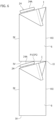
Figure 6 illustrates two packages of the type described herein mutually stacked. - In the following description, various specific details are illustrated aimed at a thorough understanding of the embodiments. The embodiments may be implemented without one or more of the specific details, or with other methods, components, materials, etc. In other cases, known structures, materials or operations are not shown or described in detail to avoid obscuring various aspects of the embodiments.
- The references used here are only for convenience and do not therefore define the field of protection or the scope of the embodiments.
- As indicated at the beginning, the package described here is, in particular, intended for the packaging of liquid products or, in any case, flowable products such as, for example, granular products.
- With reference to
Figures 1-4 , the package described here - indicated overall with the reference number 1- comprises acontainer 2 having: - an
upper wall 4; - a
lower wall 5; and -
side walls - The
container 2 is made from a folded and sealedsheet 100. Thesheet 100, of which an embodiment example is shown inFigure 5 , may be of the conventional type. As is known, the sheets used to produce containers for applications of the type in question usually have a multilayer structure formed by the overlapping of layers of different materials with various functions such as, for example, structural, thermal insulation, protection from light, barrier function with respect to contamination by external agents, reciprocal connection of sheet layers, etc. In this regard, thesheet 100 may, for example, have a multilayer structure formed by the overlapping of layers, respectively, of paper or cardboard, aluminum, and one or more plastic materials, preferably polyethylene. In any case, these aspects are beyond the innovative aspects of the solution described here and, therefore, will not be described here in further detail. - The walls 4-8 of the
container 2 are delimited by respective perimeters. - Preferably, each perimeter of the walls 4-8 includes folding and/or sealing lines of the
sheet 100, which connect the respective wall to the adjacent walls of thecontainer 2. - According to an important characteristic of the solution described here, the respective perimeters of the upper and
lower walls upper wall 4 is inclined with respect to thelower wall 5, preferably so that a vertex A of the perimeter of theupper wall 4 is at a shorter distance from thelower wall 5, with respect to the other two vertices B, C of the same perimeter. The vertices B and C may be at the same distance or at different distances from thelower wall 5. - The
upper wall 4 is inclined with respect to thelower wall 5 at an angle between 3° and 30°, preferably between 23° and 25°, even more preferably at an angle of 23.5°. - Preferably, the perimeter of the
upper wall 4 is formed by sides I, II, III, which define an isosceles triangle. - Preferably, the perimeter of the
lower wall 5 is formed by sides IV, V, VI, which define an equilateral triangle. - In alternative embodiments, on the contrary, the perimeter of the
upper wall 4 defines an equilateral triangle, while the perimeter of thelower wall 5 defines an isosceles triangle. - In one or more preferred embodiments, such as that illustrated in the container 2:
- the
side wall 6 is delimited by a trapezoidal perimeter; - the
side wall 7 is delimited by a rectangular perimeter; - the
side wall 8 is delimited by a trapezoidal perimeter; - In particular, in one or more preferred embodiments, such as that illustrated, the perimeter of the
side wall 6 is formed by sides I, IV, VII and IX. - The perimeter of the
side wall 7 is formed by sides II, V, VII and VIII. - The perimeter of the
side wall 8 is formed by sides III, VI, VIII and IX. - The sides VII, VIII, IX are vertical.
- In one or more preferred embodiments, such as that illustrated, the
container 2 comprises two flaps 11 - of which only one is visible in the figures -, which are connected to theupper wall 4, and are folded against the twoside walls flap 11 is folded around the folding line I, and is placed against theside wall 6, while theother flap 11 is folded around the folding line III and is placed against theside wall 8. These flaps are obtained as a result of folding thesheet 100 to produce thecontainer 2 according to the shape indicated above. With reference to this shape, the difference in length between the two sides VIII and VII and the side IX is ≤ 40% of the height of the triangular perimeter of theupper wall 4 considering side II as the base of the triangle. - In this way, the two
flaps 11 remain within the side dimensions of thecorresponding side walls side wall 7. - In one or more preferred embodiments, such as that illustrated, an
opening 4A closed by a tear-off or removable film is formed on theupper wall 4. - The
opening 4A is in a position displaced from the center of gravity of the triangular area of theupper wall 4 towards the vertex A, centered on an axis of symmetry K of the triangular area of theupper wall 4. - The
opening 4A defines an outlet through which to dispense the product contained in thecontainer 2. - The particular positioning of the
opening 4A in the lower region of theupper wall 4 favors the generation of a stable and constant flow of product through the opening. - This is due to the fact that the region underneath the
upper wall 4 tends - precisely due to the particular position of theopening 4A - to fill with air, thus preventing the formation of areas in vacuum, inside thecontainer 2, which would tend instead to block the outgoing flow of product. - In addition, the convergence of the
walls opening 4A, which is determined by the triangular shape of thewall 4, prevents the formation of product accumulation areas near theopening 4A, when thecontainer 2 is tilted to dispense the product. These areas are, instead, present in the solutions of the prior art, and are responsible for both an instability of the outgoing flow of product, and a difficulty in completely emptying the container. - In view of the above, the dispensing of the product from the
container 2 of the package described here is, therefore, significantly improved compared to the solutions of the prior art. - In one or more preferred embodiments, such as that illustrated, the
package 1 further comprises a closing device 20 fixed on theupper wall 4 at theopening 4A. - In one or more preferred embodiments, such as that illustrated, the closing device 20 comprises:
- a base 22 comprising an
inlet 22A, anoutlet 22B and atubular portion 22C, which connects theinlet 22A and theoutlet 22B; - a
cap 24, which is mounted on thetubular portion 22C of thebase 22, and closes theoutlet 22B of thebase 22 for preventing fluid communication between the inside of thecontainer 2 and the outside. - The
cap 24 may be removable to open and close theoutlet 22B, or, again for the same purpose, it can be movably mounted on thetubular portion 22C between two distinct positions wherein theoutlet 22B is selectively opened or closed. Thecap 24, is rotatably mounted, around a reference axis Y, on thetubular portion 22C. - The
base 22 is fixed to theupper wall 4 in a condition wherein theinlet 22A faces or engages theopening 4A of the same wall. - With reference to
Figures 3 and 4 , in one or more preferred embodiments, such as that illustrated, thecap 24 includes a top region 24' such as to define at least two points P1, P2 on the same horizontal plane O, which also contains the side II. The two points P1 and P2 lie on the same horizontal line R, which is substantially parallel to the side II. The plane O is parallel to thelower wall 5. - In this way, the two points P1, P2 and the side II identify an ideal support surface for a homologous package placed above the
package 1. - In one or more preferred embodiments, such as that illustrated, the
cap 24 comprises agripping portion 24A, intended to be grasped by the consumer for opening the package, which protrudes radially from thetubular portion 22C of thebase 22, and generally has a planar conformation extending parallelly to theupper wall 4. - Due to the particular orientation of the
gripping portion 24A, the top region 24' is defined by a peripheral region of thegripping portion 24A, which is found precisely in the highest position of thepackage 1, when thecap 24 is in the closed condition. - In one or more preferred embodiments, such as that illustrated, the gripping
portion 24A has an extension such as to cover at least 50% of the triangular area of theupper wall 4 at the top. At the same time, the grippingportion 24A has a non-circular perimeter profile, such as to remain within the side dimensions of theupper wall 4, when thecap 24 is in the closed position. - Thanks to the characteristics indicated above, the
cap 24 is able to perform a useful function in stacking thepackage 1 with other packages, and at the same time it may constitute a significant element in determining the overall aesthetic appearance of thepackage 1. Furthermore, the relevant dimensions of thecap 24 facilitate its grip by the user. - In one or more preferred embodiments, such as that illustrated, the gripping
portion 24A may have a plan profile - in the example shown a heart shape - such as to define a recess 24C designed to receive at least one finger of the user. -
Figure 5 illustrates an example of asheet 100 for producing the container described above. In a per se known manner, thesheet 100 has aperimeter edge 101 of a predetermined shape, andpredefined folding lines 102, to facilitate the folding of the sheet in a predetermined way, to form thecontainer 2 illustrated inFigures 1-4 , during the relative forming process. As is known to those skilled in the art, theperimeter edge 101 and the formation of thefolding lines 102 may vary according to the requirements of the specific applications and according to the forming method used. - In the example of
Figure 4 ,references sheet 100 identified by thefolding lines 102, which form thewalls - Moreover, the formation of the folding lines comprises three lines 102(1), 102(11), 102(111), parallel to each other, which, in the folded condition of the sheet, connect the
side walls - The folding line 102(11) is shorter than the other two folding lines 102(1), 102(111), so as to determine the inclined condition illustrated above of the
upper wall 4 with respect to thelower wall 5. -
Figure 5 also illustrates aperimeter band 106, which represents the area along which the partially foldedsheet 100 is sealed to obtain a semifinished product of thecontainer 2, which is completely closed and contains the product inside, and which is then subjected to successive folding steps to form thecontainer 2 in the final shape indicated above. In general, according to the specific configuration of thesheet 100, this sealing area may determine, in thecontainer 2, one or more sealing lines, which each define one side of one of the perimeters of the different walls of the container. - Of course, without prejudice to the principle of the invention, the details of construction and the embodiments may vary, even significantly, with respect to those illustrated here, purely by way of non-limiting example, without departing from the scope of the invention as defined by the attached claims.
Claims (15)
- A package (1) comprising a container (2) formed by a folded and sealed sheet (100), the container (2) including:- an upper wall (4) delimited by a first perimeter (I, II, III) of triangular shape;- a lower wall (5) opposite said upper wall (4) and delimited by a second perimeter (IV, V, VI) of triangular shape, said upper wall (4) being inclined with respect to said lower wall (5);- a first side wall (7) delimited by a third perimeter (II, V, VII, VIII) of rectangular shape;- a second side wall (6) delimited by a fourth perimeter (I, IV, VII, IX) of trapezoidal shape; and- a third side wall (8) delimited by a fifth perimeter (III, VI, VIII, IX) of trapezoidal shape;
wherein a difference in length between the major base (VII) and the minor base (IX) of one of said fourth perimeter (I, IV, VII, IX) and fifth perimeter (III, VI, VIII, IX) is less than or equal to 40% of a height of said first perimeter (I, II, III), said height being defined with respect to a side (II) of said first perimeter (I, II, III) in common with said third perimeter (II, V, VII, VIII). - A package according to claim 1, wherein said upper wall (4) is inclined according to an angle in the range between 3° and 30°, preferably in the range between 23° and 25°, even more preferably according to an angle equal to 23.5°.
- A package according to claims 1 or 2, wherein said first perimeter (I, II, III) defines an isosceles triangle and said second perimeter (IV, V, VI) defines an equilateral triangle, or vice versa.
- A package according to any of the previous claims, wherein an opening (4A) is obtained on said upper wall (4) of said container (2).
- A package according to claim 4, wherein said opening (4A) of said upper wall (4) is closed by a tear-off or removable film.
- A package according to claims 4 or 5, wherein said first perimeter (I, II, III) and said opening (4A) of said upper wall (4) have a respective center of gravity, and the center of gravity of said opening (4A) is in a position displaced from the center of gravity of said first perimeter (I, II, III), towards a vertex (A) of said first perimeter (I, II, III), which is at a shorter distance from said lower wall (5), with respect to two other vertices (B, C) of said first perimeter (I, II, III).
- A package according to any one of claims 4 to 6, wherein said opening (4A) of said upper wall (4) is centered on an axis of symmetry (K) of a triangular area delimited by said first perimeter (I, II, III).
- A package according to any one of claims 4 to 7, further comprises a closing device (20) fixed on said upper wall (4) at said opening (4A).
- A package according to claim 8, wherein said closing device (20) comprises:- a base (22) comprising an inlet (22A), an outlet (22B) and a tubular portion (22C), which connects the inlet (22A) and outlet (22B), said base (22) being preferably fixed to the container at the opening (4A) of the upper wall (4), in a condition wherein the inlet (22A) faces the opening (4A) in the upper wall (4);- a cap (24) that is mounted, preferably rotatably, around a reference axis (Y), on the tubular portion (22C) of the base (22), and closes the outlet (22B) of the base to prevent fluid communication between the inside of the container (2) and the outside.
- A package according to claim 9, wherein the cap (24) includes a top region (24'), which comprises at least two points (P1, P2) belonging to the same upper plane (O), which also contains a side (II) of the first perimeter (I, II, III), said upper plane (O) being parallel or substantially parallel to said lower wall (5).
- A package according to claim 10, wherein said at least two points (P1, P2) lie on the same line (R), substantially parallel to said side (II) of the first perimeter (I, II, III).
- A package according to any one of claims 9 to 11, wherein said cap (24) comprises a gripping portion (24A), which protrudes radially from the tubular portion (24C) of the base and extends, on a plane perpendicular to the reference axis (Y), to cover at least 50% of a triangular area delimited by the first perimeter (I, II, III), and preferably has a non-circular perimeter profile so as to remain within the side dimensions of the first perimeter (I, II, III), in a predetermined closing position of the cap (24).
- A package according to any one of the preceding claims, wherein said first perimeter (I, II, III) includes a first series of folding and/or sealing lines of the sheet (100), which connect said upper wall (4) to said side walls (6, 7, 8), and said second perimeter (IV, V, VI) includes a second series of folding and/or sealing lines of the sheet (100) that connect said lower wall (5) to said side walls (6, 7, 8).
- A package according to claim 13, wherein:- said third perimeter (II, V, VII, VIII) includes a first folding or sealing line (II) of the first series, a first (V) folding or sealing line of the second series, and a first and a second folding or sealing line (VII, VIII), vertical, which have the same length;- said fourth perimeter (I, IV, VII, IX) includes a second folding or sealing line (I) of the first series, a second folding or sealing line (IV) of the second series, said first vertical folding or sealing line (VII), and a third vertical folding or sealing line (IX) which has a shorter length than the first vertical folding or sealing line (VII);- the fifth perimeter (III, VI, VIII, IX) includes a third folding or sealing line (III) of the first series, a third folding or sealing line (VI) of the second series, said second vertical folding or sealing line (VIII) and said third vertical folding or sealing line (IX).
- A package according to any one of the preceding claims, comprising two flaps (11), which are connected to said upper wall (4) and are folded respectively against said second and third side walls (6, 8), preferably around a folding line (I), which defines one side of said first perimeter (I, II, III) in common with said fourth perimeter (I, IV, VII, IX), and around a folding line (III), which defines one side of said first perimeter (I, II, III) in common with said fifth perimeter (III, VI, VIII, IX), respectively.
Applications Claiming Priority (1)
| Application Number | Priority Date | Filing Date | Title |
|---|---|---|---|
| IT102021000027149A IT202100027149A1 (en) | 2021-10-22 | 2021-10-22 | PACKAGING |
Publications (2)
| Publication Number | Publication Date |
|---|---|
| EP4169842A2 true EP4169842A2 (en) | 2023-04-26 |
| EP4169842A3 EP4169842A3 (en) | 2023-07-19 |
Family
ID=79270264
Family Applications (1)
| Application Number | Title | Priority Date | Filing Date |
|---|---|---|---|
| EP22202700.5A Withdrawn EP4169842A3 (en) | 2021-10-22 | 2022-10-20 | Package |
Country Status (2)
| Country | Link |
|---|---|
| EP (1) | EP4169842A3 (en) |
| IT (1) | IT202100027149A1 (en) |
Family Cites Families (2)
| Publication number | Priority date | Publication date | Assignee | Title |
|---|---|---|---|---|
| GB512344A (en) * | 1938-04-21 | 1939-09-01 | Dennis Wood | Improvements in cartons or like containers for liquids, powders or the like |
| US20130292459A1 (en) * | 2010-12-07 | 2013-11-07 | Tetra Laval Holdings & Finance S.A. | Method of manufacturing packaging container and packaging container |
-
2021
- 2021-10-22 IT IT102021000027149A patent/IT202100027149A1/en unknown
-
2022
- 2022-10-20 EP EP22202700.5A patent/EP4169842A3/en not_active Withdrawn
Also Published As
| Publication number | Publication date |
|---|---|
| IT202100027149A1 (en) | 2023-04-22 |
| EP4169842A3 (en) | 2023-07-19 |
Similar Documents
| Publication | Publication Date | Title |
|---|---|---|
| EP2755897B1 (en) | Economically improved plastic bottle and package system | |
| US3933268A (en) | Container | |
| US20190152671A1 (en) | Container Assemblies For Storing, Shipping, And/Or Dispensing Fluids, And Related Methods | |
| US4877142A (en) | Rectangular bottle for motor oil and like fluids | |
| EP2249677B1 (en) | Stackable cosmetic jar | |
| US20040226989A1 (en) | Portable food dispenser | |
| CZ20021491A3 (en) | Re-sealable container with a pouring orifice | |
| CN87102207A (en) | liquid container with handle | |
| JPS6031701B2 (en) | Two-way fitting liquid container | |
| US6817473B2 (en) | Household product package with tamper evident cap | |
| CN103228543A (en) | Production method for packaging container and packaging container | |
| MX2013001532A (en) | Method for forming a package, a package and a package blank. | |
| US6168039B1 (en) | Household product package | |
| CA2787988C (en) | Flexible package particularly for liquid products | |
| FI128014B (en) | Box for Bag-in-Box package | |
| GB2310194A (en) | Forming a closure on a self-standing bag | |
| IT202100027149A1 (en) | PACKAGING | |
| CN1103372A (en) | Bottle-like plastic container | |
| JP2004520242A (en) | Container bottom and method | |
| RU119327U1 (en) | THERMOFORMED FOOD CONTAINER (OPTIONS) | |
| CA2944615C (en) | Semi-rigid shipping container with peel-reseal closure | |
| US20040262375A1 (en) | Handled container | |
| EP0887280A1 (en) | Exterior package for packaging containers | |
| JP2004513036A (en) | Removable closure device | |
| WO2001032529A1 (en) | Bag-in-box container having grip assist |
Legal Events
| Date | Code | Title | Description |
|---|---|---|---|
| PUAI | Public reference made under article 153(3) epc to a published international application that has entered the european phase |
Free format text: ORIGINAL CODE: 0009012 |
|
| STAA | Information on the status of an ep patent application or granted ep patent |
Free format text: STATUS: THE APPLICATION HAS BEEN PUBLISHED |
|
| AK | Designated contracting states |
Kind code of ref document: A2 Designated state(s): AL AT BE BG CH CY CZ DE DK EE ES FI FR GB GR HR HU IE IS IT LI LT LU LV MC ME MK MT NL NO PL PT RO RS SE SI SK SM TR |
|
| PUAL | Search report despatched |
Free format text: ORIGINAL CODE: 0009013 |
|
| AK | Designated contracting states |
Kind code of ref document: A3 Designated state(s): AL AT BE BG CH CY CZ DE DK EE ES FI FR GB GR HR HU IE IS IT LI LT LU LV MC ME MK MT NL NO PL PT RO RS SE SI SK SM TR |
|
| RIC1 | Information provided on ipc code assigned before grant |
Ipc: B65D 5/06 20060101ALI20230612BHEP Ipc: B65D 5/02 20060101AFI20230612BHEP |
|
| STAA | Information on the status of an ep patent application or granted ep patent |
Free format text: STATUS: THE APPLICATION IS DEEMED TO BE WITHDRAWN |
|
| 18D | Application deemed to be withdrawn |
Effective date: 20240120 |