EP4169766A1 - Vehicle battery overcharging prevention system and method - Google Patents
Vehicle battery overcharging prevention system and method Download PDFInfo
- Publication number
- EP4169766A1 EP4169766A1 EP21880475.5A EP21880475A EP4169766A1 EP 4169766 A1 EP4169766 A1 EP 4169766A1 EP 21880475 A EP21880475 A EP 21880475A EP 4169766 A1 EP4169766 A1 EP 4169766A1
- Authority
- EP
- European Patent Office
- Prior art keywords
- power
- battery
- reduction
- output
- charger
- Prior art date
- Legal status (The legal status is an assumption and is not a legal conclusion. Google has not performed a legal analysis and makes no representation as to the accuracy of the status listed.)
- Pending
Links
Images
Classifications
-
- B—PERFORMING OPERATIONS; TRANSPORTING
- B60—VEHICLES IN GENERAL
- B60L—PROPULSION OF ELECTRICALLY-PROPELLED VEHICLES; SUPPLYING ELECTRIC POWER FOR AUXILIARY EQUIPMENT OF ELECTRICALLY-PROPELLED VEHICLES; ELECTRODYNAMIC BRAKE SYSTEMS FOR VEHICLES IN GENERAL; MAGNETIC SUSPENSION OR LEVITATION FOR VEHICLES; MONITORING OPERATING VARIABLES OF ELECTRICALLY-PROPELLED VEHICLES; ELECTRIC SAFETY DEVICES FOR ELECTRICALLY-PROPELLED VEHICLES
- B60L1/00—Supplying electric power to auxiliary equipment of vehicles
- B60L1/003—Supplying electric power to auxiliary equipment of vehicles to auxiliary motors, e.g. for pumps, compressors
-
- B—PERFORMING OPERATIONS; TRANSPORTING
- B60—VEHICLES IN GENERAL
- B60L—PROPULSION OF ELECTRICALLY-PROPELLED VEHICLES; SUPPLYING ELECTRIC POWER FOR AUXILIARY EQUIPMENT OF ELECTRICALLY-PROPELLED VEHICLES; ELECTRODYNAMIC BRAKE SYSTEMS FOR VEHICLES IN GENERAL; MAGNETIC SUSPENSION OR LEVITATION FOR VEHICLES; MONITORING OPERATING VARIABLES OF ELECTRICALLY-PROPELLED VEHICLES; ELECTRIC SAFETY DEVICES FOR ELECTRICALLY-PROPELLED VEHICLES
- B60L1/00—Supplying electric power to auxiliary equipment of vehicles
- B60L1/006—Supplying electric power to auxiliary equipment of vehicles to power outlets
-
- B—PERFORMING OPERATIONS; TRANSPORTING
- B60—VEHICLES IN GENERAL
- B60L—PROPULSION OF ELECTRICALLY-PROPELLED VEHICLES; SUPPLYING ELECTRIC POWER FOR AUXILIARY EQUIPMENT OF ELECTRICALLY-PROPELLED VEHICLES; ELECTRODYNAMIC BRAKE SYSTEMS FOR VEHICLES IN GENERAL; MAGNETIC SUSPENSION OR LEVITATION FOR VEHICLES; MONITORING OPERATING VARIABLES OF ELECTRICALLY-PROPELLED VEHICLES; ELECTRIC SAFETY DEVICES FOR ELECTRICALLY-PROPELLED VEHICLES
- B60L3/00—Electric devices on electrically-propelled vehicles for safety purposes; Monitoring operating variables, e.g. speed, deceleration or energy consumption
- B60L3/0023—Detecting, eliminating, remedying or compensating for drive train abnormalities, e.g. failures within the drive train
- B60L3/0046—Detecting, eliminating, remedying or compensating for drive train abnormalities, e.g. failures within the drive train relating to electric energy storage systems, e.g. batteries or capacitors
-
- B—PERFORMING OPERATIONS; TRANSPORTING
- B60—VEHICLES IN GENERAL
- B60L—PROPULSION OF ELECTRICALLY-PROPELLED VEHICLES; SUPPLYING ELECTRIC POWER FOR AUXILIARY EQUIPMENT OF ELECTRICALLY-PROPELLED VEHICLES; ELECTRODYNAMIC BRAKE SYSTEMS FOR VEHICLES IN GENERAL; MAGNETIC SUSPENSION OR LEVITATION FOR VEHICLES; MONITORING OPERATING VARIABLES OF ELECTRICALLY-PROPELLED VEHICLES; ELECTRIC SAFETY DEVICES FOR ELECTRICALLY-PROPELLED VEHICLES
- B60L53/00—Methods of charging batteries, specially adapted for electric vehicles; Charging stations or on-board charging equipment therefor; Exchange of energy storage elements in electric vehicles
- B60L53/10—Methods of charging batteries, specially adapted for electric vehicles; Charging stations or on-board charging equipment therefor; Exchange of energy storage elements in electric vehicles characterised by the energy transfer between the charging station and the vehicle
- B60L53/14—Conductive energy transfer
-
- B—PERFORMING OPERATIONS; TRANSPORTING
- B60—VEHICLES IN GENERAL
- B60L—PROPULSION OF ELECTRICALLY-PROPELLED VEHICLES; SUPPLYING ELECTRIC POWER FOR AUXILIARY EQUIPMENT OF ELECTRICALLY-PROPELLED VEHICLES; ELECTRODYNAMIC BRAKE SYSTEMS FOR VEHICLES IN GENERAL; MAGNETIC SUSPENSION OR LEVITATION FOR VEHICLES; MONITORING OPERATING VARIABLES OF ELECTRICALLY-PROPELLED VEHICLES; ELECTRIC SAFETY DEVICES FOR ELECTRICALLY-PROPELLED VEHICLES
- B60L58/00—Methods or circuit arrangements for monitoring or controlling batteries or fuel cells, specially adapted for electric vehicles
- B60L58/10—Methods or circuit arrangements for monitoring or controlling batteries or fuel cells, specially adapted for electric vehicles for monitoring or controlling batteries
- B60L58/12—Methods or circuit arrangements for monitoring or controlling batteries or fuel cells, specially adapted for electric vehicles for monitoring or controlling batteries responding to state of charge [SoC]
- B60L58/13—Maintaining the SoC within a determined range
-
- B—PERFORMING OPERATIONS; TRANSPORTING
- B60—VEHICLES IN GENERAL
- B60L—PROPULSION OF ELECTRICALLY-PROPELLED VEHICLES; SUPPLYING ELECTRIC POWER FOR AUXILIARY EQUIPMENT OF ELECTRICALLY-PROPELLED VEHICLES; ELECTRODYNAMIC BRAKE SYSTEMS FOR VEHICLES IN GENERAL; MAGNETIC SUSPENSION OR LEVITATION FOR VEHICLES; MONITORING OPERATING VARIABLES OF ELECTRICALLY-PROPELLED VEHICLES; ELECTRIC SAFETY DEVICES FOR ELECTRICALLY-PROPELLED VEHICLES
- B60L58/00—Methods or circuit arrangements for monitoring or controlling batteries or fuel cells, specially adapted for electric vehicles
- B60L58/10—Methods or circuit arrangements for monitoring or controlling batteries or fuel cells, specially adapted for electric vehicles for monitoring or controlling batteries
- B60L58/12—Methods or circuit arrangements for monitoring or controlling batteries or fuel cells, specially adapted for electric vehicles for monitoring or controlling batteries responding to state of charge [SoC]
- B60L58/15—Preventing overcharging
-
- B—PERFORMING OPERATIONS; TRANSPORTING
- B60—VEHICLES IN GENERAL
- B60W—CONJOINT CONTROL OF VEHICLE SUB-UNITS OF DIFFERENT TYPE OR DIFFERENT FUNCTION; CONTROL SYSTEMS SPECIALLY ADAPTED FOR HYBRID VEHICLES; ROAD VEHICLE DRIVE CONTROL SYSTEMS FOR PURPOSES NOT RELATED TO THE CONTROL OF A PARTICULAR SUB-UNIT
- B60W10/00—Conjoint control of vehicle sub-units of different type or different function
- B60W10/04—Conjoint control of vehicle sub-units of different type or different function including control of propulsion units
- B60W10/08—Conjoint control of vehicle sub-units of different type or different function including control of propulsion units including control of electric propulsion units, e.g. motors or generators
-
- B—PERFORMING OPERATIONS; TRANSPORTING
- B60—VEHICLES IN GENERAL
- B60W—CONJOINT CONTROL OF VEHICLE SUB-UNITS OF DIFFERENT TYPE OR DIFFERENT FUNCTION; CONTROL SYSTEMS SPECIALLY ADAPTED FOR HYBRID VEHICLES; ROAD VEHICLE DRIVE CONTROL SYSTEMS FOR PURPOSES NOT RELATED TO THE CONTROL OF A PARTICULAR SUB-UNIT
- B60W10/00—Conjoint control of vehicle sub-units of different type or different function
- B60W10/30—Conjoint control of vehicle sub-units of different type or different function including control of auxiliary equipment, e.g. air-conditioning compressors or oil pumps
-
- B—PERFORMING OPERATIONS; TRANSPORTING
- B60—VEHICLES IN GENERAL
- B60W—CONJOINT CONTROL OF VEHICLE SUB-UNITS OF DIFFERENT TYPE OR DIFFERENT FUNCTION; CONTROL SYSTEMS SPECIALLY ADAPTED FOR HYBRID VEHICLES; ROAD VEHICLE DRIVE CONTROL SYSTEMS FOR PURPOSES NOT RELATED TO THE CONTROL OF A PARTICULAR SUB-UNIT
- B60W20/00—Control systems specially adapted for hybrid vehicles
- B60W20/10—Controlling the power contribution of each of the prime movers to meet required power demand
- B60W20/13—Controlling the power contribution of each of the prime movers to meet required power demand in order to stay within battery power input or output limits; in order to prevent overcharging or battery depletion
-
- B—PERFORMING OPERATIONS; TRANSPORTING
- B60—VEHICLES IN GENERAL
- B60W—CONJOINT CONTROL OF VEHICLE SUB-UNITS OF DIFFERENT TYPE OR DIFFERENT FUNCTION; CONTROL SYSTEMS SPECIALLY ADAPTED FOR HYBRID VEHICLES; ROAD VEHICLE DRIVE CONTROL SYSTEMS FOR PURPOSES NOT RELATED TO THE CONTROL OF A PARTICULAR SUB-UNIT
- B60W30/00—Purposes of road vehicle drive control systems not related to the control of a particular sub-unit, e.g. of systems using conjoint control of vehicle sub-units
- B60W30/18—Propelling the vehicle
- B60W30/188—Controlling power parameters of the driveline, e.g. determining the required power
- B60W30/1886—Controlling power supply to auxiliary devices
- B60W30/1888—Control of power take off [PTO]
-
- H—ELECTRICITY
- H02—GENERATION; CONVERSION OR DISTRIBUTION OF ELECTRIC POWER
- H02J—ELECTRIC POWER NETWORKS; CIRCUIT ARRANGEMENTS OR SYSTEMS FOR SUPPLYING OR DISTRIBUTING ELECTRIC POWER; SYSTEMS FOR STORING ELECTRIC ENERGY
- H02J7/00—Circuit arrangements for charging or discharging batteries or for supplying loads from batteries
- H02J7/60—Circuit arrangements for charging or discharging batteries or for supplying loads from batteries including safety or protection arrangements
- H02J7/61—Circuit arrangements for charging or discharging batteries or for supplying loads from batteries including safety or protection arrangements against overcharge
-
- H—ELECTRICITY
- H02—GENERATION; CONVERSION OR DISTRIBUTION OF ELECTRIC POWER
- H02J—ELECTRIC POWER NETWORKS; CIRCUIT ARRANGEMENTS OR SYSTEMS FOR SUPPLYING OR DISTRIBUTING ELECTRIC POWER; SYSTEMS FOR STORING ELECTRIC ENERGY
- H02J7/00—Circuit arrangements for charging or discharging batteries or for supplying loads from batteries
- H02J7/90—Regulation of charging or discharging current or voltage
- H02J7/933—Regulation of charging or discharging current or voltage the cycle being controlled or terminated in response to electric parameters
-
- B—PERFORMING OPERATIONS; TRANSPORTING
- B60—VEHICLES IN GENERAL
- B60L—PROPULSION OF ELECTRICALLY-PROPELLED VEHICLES; SUPPLYING ELECTRIC POWER FOR AUXILIARY EQUIPMENT OF ELECTRICALLY-PROPELLED VEHICLES; ELECTRODYNAMIC BRAKE SYSTEMS FOR VEHICLES IN GENERAL; MAGNETIC SUSPENSION OR LEVITATION FOR VEHICLES; MONITORING OPERATING VARIABLES OF ELECTRICALLY-PROPELLED VEHICLES; ELECTRIC SAFETY DEVICES FOR ELECTRICALLY-PROPELLED VEHICLES
- B60L2240/00—Control parameters of input or output; Target parameters
- B60L2240/40—Drive Train control parameters
- B60L2240/54—Drive Train control parameters related to batteries
- B60L2240/549—Current
-
- B—PERFORMING OPERATIONS; TRANSPORTING
- B60—VEHICLES IN GENERAL
- B60W—CONJOINT CONTROL OF VEHICLE SUB-UNITS OF DIFFERENT TYPE OR DIFFERENT FUNCTION; CONTROL SYSTEMS SPECIALLY ADAPTED FOR HYBRID VEHICLES; ROAD VEHICLE DRIVE CONTROL SYSTEMS FOR PURPOSES NOT RELATED TO THE CONTROL OF A PARTICULAR SUB-UNIT
- B60W2510/00—Input parameters relating to a particular sub-units
- B60W2510/24—Energy storage means
- B60W2510/242—Energy storage means for electrical energy
- B60W2510/244—Charge state
-
- G—PHYSICS
- G01—MEASURING; TESTING
- G01R—MEASURING ELECTRIC VARIABLES; MEASURING MAGNETIC VARIABLES
- G01R31/00—Arrangements for testing electric properties; Arrangements for locating electric faults; Arrangements for electrical testing characterised by what is being tested not provided for elsewhere
- G01R31/36—Arrangements for testing, measuring or monitoring the electrical condition of accumulators or electric batteries, e.g. capacity or state of charge [SoC]
- G01R31/382—Arrangements for monitoring battery or accumulator variables, e.g. SoC
-
- Y—GENERAL TAGGING OF NEW TECHNOLOGICAL DEVELOPMENTS; GENERAL TAGGING OF CROSS-SECTIONAL TECHNOLOGIES SPANNING OVER SEVERAL SECTIONS OF THE IPC; TECHNICAL SUBJECTS COVERED BY FORMER USPC CROSS-REFERENCE ART COLLECTIONS [XRACs] AND DIGESTS
- Y02—TECHNOLOGIES OR APPLICATIONS FOR MITIGATION OR ADAPTATION AGAINST CLIMATE CHANGE
- Y02T—CLIMATE CHANGE MITIGATION TECHNOLOGIES RELATED TO TRANSPORTATION
- Y02T10/00—Road transport of goods or passengers
- Y02T10/60—Other road transportation technologies with climate change mitigation effect
- Y02T10/70—Energy storage systems for electromobility, e.g. batteries
-
- Y—GENERAL TAGGING OF NEW TECHNOLOGICAL DEVELOPMENTS; GENERAL TAGGING OF CROSS-SECTIONAL TECHNOLOGIES SPANNING OVER SEVERAL SECTIONS OF THE IPC; TECHNICAL SUBJECTS COVERED BY FORMER USPC CROSS-REFERENCE ART COLLECTIONS [XRACs] AND DIGESTS
- Y02—TECHNOLOGIES OR APPLICATIONS FOR MITIGATION OR ADAPTATION AGAINST CLIMATE CHANGE
- Y02T—CLIMATE CHANGE MITIGATION TECHNOLOGIES RELATED TO TRANSPORTATION
- Y02T10/00—Road transport of goods or passengers
- Y02T10/60—Other road transportation technologies with climate change mitigation effect
- Y02T10/7072—Electromobility specific charging systems or methods for batteries, ultracapacitors, supercapacitors or double-layer capacitors
-
- Y—GENERAL TAGGING OF NEW TECHNOLOGICAL DEVELOPMENTS; GENERAL TAGGING OF CROSS-SECTIONAL TECHNOLOGIES SPANNING OVER SEVERAL SECTIONS OF THE IPC; TECHNICAL SUBJECTS COVERED BY FORMER USPC CROSS-REFERENCE ART COLLECTIONS [XRACs] AND DIGESTS
- Y02—TECHNOLOGIES OR APPLICATIONS FOR MITIGATION OR ADAPTATION AGAINST CLIMATE CHANGE
- Y02T—CLIMATE CHANGE MITIGATION TECHNOLOGIES RELATED TO TRANSPORTATION
- Y02T10/00—Road transport of goods or passengers
- Y02T10/80—Technologies aiming to reduce greenhouse gasses emissions common to all road transportation technologies
- Y02T10/92—Energy efficient charging or discharging systems for batteries, ultracapacitors, supercapacitors or double-layer capacitors specially adapted for vehicles
-
- Y—GENERAL TAGGING OF NEW TECHNOLOGICAL DEVELOPMENTS; GENERAL TAGGING OF CROSS-SECTIONAL TECHNOLOGIES SPANNING OVER SEVERAL SECTIONS OF THE IPC; TECHNICAL SUBJECTS COVERED BY FORMER USPC CROSS-REFERENCE ART COLLECTIONS [XRACs] AND DIGESTS
- Y02—TECHNOLOGIES OR APPLICATIONS FOR MITIGATION OR ADAPTATION AGAINST CLIMATE CHANGE
- Y02T—CLIMATE CHANGE MITIGATION TECHNOLOGIES RELATED TO TRANSPORTATION
- Y02T90/00—Enabling technologies or technologies with a potential or indirect contribution to GHG emissions mitigation
- Y02T90/10—Technologies relating to charging of electric vehicles
- Y02T90/12—Electric charging stations
-
- Y—GENERAL TAGGING OF NEW TECHNOLOGICAL DEVELOPMENTS; GENERAL TAGGING OF CROSS-SECTIONAL TECHNOLOGIES SPANNING OVER SEVERAL SECTIONS OF THE IPC; TECHNICAL SUBJECTS COVERED BY FORMER USPC CROSS-REFERENCE ART COLLECTIONS [XRACs] AND DIGESTS
- Y02—TECHNOLOGIES OR APPLICATIONS FOR MITIGATION OR ADAPTATION AGAINST CLIMATE CHANGE
- Y02T—CLIMATE CHANGE MITIGATION TECHNOLOGIES RELATED TO TRANSPORTATION
- Y02T90/00—Enabling technologies or technologies with a potential or indirect contribution to GHG emissions mitigation
- Y02T90/10—Technologies relating to charging of electric vehicles
- Y02T90/16—Information or communication technologies improving the operation of electric vehicles
Definitions
- the present invention relates to a method for preventing overcharging of a vehicle battery, and more particularly, to a method for preventing overcharging of a battery used in a vehicle equipped with an E-TPO.
- the battery of such an electric vehicle Since a number of rechargeable batteries that may be charged and discharged are formed in one pack, and the battery must be charged from an external charger, the battery of such an electric vehicle has a large influence on the mileage of the electric vehicle according to the capacity and charging state of the battery.
- E-PTO Electric Power Take Off
- the power not consumed by the E-PTO may overcharge the battery.
- An object of the present invention is to provide a control system and method for improving efficiency in a fully charged state of a battery and preventing overcharging in an electric vehicle equipped with an E-PTO.
- An overcharge prevention method includes: an overcharge detection step of detecting overcharge of the battery; a reduction output power calculation step of calculating an average input power input to the battery in an overcharging state of the battery, and calculating a power to be reduced and output by a charger based on the calculated average input power; a charge power reduction request step of requesting a reduction in charging power to the charger based on the calculated reduction output power; a reduction charging power output step in which the charger receiving the output power reduction request outputs the reduced charging power; an overcharge battery power consumption step in which the reduced charging power output in the reduction charging power output step is input only to the E-PTO, and an insufficient power of the E-PTO is supplied from the battery to consume an overcharged battery; and a normal power output step in which the charger outputs normal power again when power of the overcharged battery is consumed and a charging state of the battery is not an overcharging state, wherein the reduction charging power output step and the normal power output step are repeated based on a battery charging state.
- the overcharge detection step includes: a charging state checking step of confirming the overcharging state of the battery; and an overcharging current input detection step of detecting and measuring an overcharging current inputted to the battery when checking overcharging of the battery.
- the reduction output power calculation step includes: an input power calculation step of calculating overcharge power using the detected overcharging current input value; an average input power calculation step of calculating an average input power using the calculated overcharge power and a detection time of the overcharging current input; and a reduction output power calculation step of calculating a reduction output power to request reduction from the charger based on the calculated average input power, wherein the reduction output power is obtained by subtracting twice the average input power from the power required by the E-PTO.
- the charge power reduction request step includes an output power reduction request step of requesting the charger to reduce output power based on the amount of reduction power.
- the overcharging state is 101% of the full charging state, and the non-overcharging state is set to 99% or less of the full charging state to maintain the charging state of the battery close to 100%.
- the electric vehicle includes: a battery configured to store electric energy supplied from a charger; a motor driven by receiving electric energy from the battery; an E-PTO configured to receive electric energy from the charger or the battery and supply power to electronic equipment that functions other than driving; and an overcharge control unit configured to control power input to the battery and the E-PTO and power output from the charger, wherein the overcharge control unit includes: a charging state detection unit configured to check a charging state of the battery; a current detection unit configured to detect an input current applied to the battery when the battery is overcharged; a power calculation unit configured to calculate an input power based on the input current, calculate an average input power using the input power and a detection time, and calculate an amount of reduction power that the charger needs to reduce charging power based on the average input power; and a power reduction request unit configured to request the calculated amount of reduction power from the charger.
- the overcharge control unit includes: a charging state detection unit configured to check a charging state of the battery; a current detection unit configured to detect an input current applied to the battery when the
- the overcharge control unit is a component of a Battery Management System (BMS) designed integrally with a battery or a component of a Vehicle Control Unit (VCU).
- BMS Battery Management System
- VCU Vehicle Control Unit
- the amount of reduction power to be reduced output calculated by the power calculation unit is calculated by subtracting twice the average input power from the power required by the E-PTO.
- an overcharge control unit including a charging state detection unit, a current detection unit, a power calculation unit, and a power reduction request unit in the VCU
- the electric vehicle detects the input current, calculates the average input power, and requests the charger to reduce the output power based on the calculated result.
- the battery in the overcharged state may temporarily receive the power required by the E-TPO from the external charger and battery.
- the VCU controls the output power of the charger so that the battery supplies a part of the requested power required by the E-PTO when the battery is overcharged, and by consuming the power of the overcharged battery, it is possible to prevent overcharging of the battery, and it is possible to improve battery charging efficiency compared to the prior art.
- the present invention includes an electric vehicle 200 including a Vehicle Control Unit (VCU), an E-PTO, and a battery, and a charger 100 for supplying electric energy to the electric vehicle 200.
- VCU Vehicle Control Unit
- E-PTO Electronic Device
- battery a charger 100 for supplying electric energy to the electric vehicle 200.
- a battery 240 stores electric energy received from the external charger 100 and supplies the stored electric energy to the motor 241 while driving.
- the battery 240 of the present invention serves to supply power not only to the driving motor 241 but also to the E-PTO 230.
- the motor 241 receives electric energy from the battery 241 and outputs the received electric energy as driving power of the electric vehicle 200.
- the E-PTO 230 receives electric energy from the external charger 100 or the battery 240 and outputs the power required to drive the external electronic equipment of the electric vehicle 200.
- the electronic equipment 231 is mounted on the electric vehicle 200 and receives power output from the E-PTO 230 to perform functions other than driving, and for example, includes various electronic equipment 231 such as a refrigerator for a refrigeration tower vehicle, a water pump for firefighting, a driving device for opening and closing a wing body, and a lifting device for high-place work.
- various electronic equipment 231 such as a refrigerator for a refrigeration tower vehicle, a water pump for firefighting, a driving device for opening and closing a wing body, and a lifting device for high-place work.
- the Vehicle Control Unit (VCU) 210 controls the power between the charger 100, the battery 240, and the E-PTO 230 in the electric vehicle 200, calculates the power input for a predetermined unit time supplied to the battery 240 in the overcharging state through the overcharge control unit 220 and the input power to be reduced based on this, and transmits this to the charger 100 to request a reduction in charging power.
- VCU Vehicle Control Unit
- the overcharge control unit 220 is configured to include a charging state detection unit 221, a current detection unit 222, a power calculation unit 223, and a power reduction request unit 224, and may be a component of a Battery Management System (BMS) designed integrally with the battery 240 or a component of the VCU 210.
- BMS Battery Management System
- the charging state detection unit 221 detects the overcharging state of the battery 240 by checking the charging state of the battery 240, that is, the SOC of the battery 240 in real time. It is determined that the overcharging state of the battery 240 exceeds a predetermined SOC upper limit value, for example, 101%.
- the battery 240 SOC upper limit value may be set variously according to system requirements, and for example, the SOC exceeding 100% of the battery 240 fully charged SOC may be set as the upper limit of the charging capacity.
- the lower limit charging capacity may be set to less than 100%.
- the current detection unit 222 detects a current value input to the battery 240.
- the detected input current value is a current continuously flowing into the battery 240 even though the battery 240 is above a predetermined reference SOC value, so it is determined as an overcharging current, and input current values for a predetermined time period are detected in order to calculate the input overcharge power amount, and at this time, the voltage applied to the battery 240 is measured together and transmitted to the power calculation unit 223.
- the power calculation unit 223 calculates the average input power, that is, the amount of overcharge power, for a predetermined time period detected by using the overcharge input current input to the battery 240 in the overcharging state and the voltage at this time. Also, the reduction power to request reduction from the charger 100 is calculated based on the calculated average input power.
- the battery 240 is in an overcharging state due to excessive power input for the predetermined time period, in order to return this to a normal state, overcharge power of the battery 240 must be consumed.
- the power output from the charger 100 is distributed and supplied to the E-PTO 230 and the battery 240, and as a method for consuming the power of the battery 240, the E-PTO 230 requests the charger to output a power smaller than the required power by requesting a reduction in the charging power output from the charger 100.
- the reduction output power requested by the charger 100 may be calculated by subtracting a greater power from the required power of the E-PTO 230 as the reduction output power, not just the overcharge power that is the average input power input to the overcharge battery 240.
- the reduction charging power that requests output from the charger may be calculated as power obtained by subtracting twice the average input power (overcharge power) of the overcharging state battery 240 from the required power of the E-PTO 230.
- the power reduction request unit 224 transmits to the charger 100 the power that the calculated reduction output power is reduced to output the reduction charging power.
- the SOC of the battery 240 detected by the charging state detection unit 221 is detected to be less than or equal to a predetermined value, for example, 99%, the reduction output request is stopped and a normal charging is requested.
- the charger 100 is connected to the electric vehicle 200 and receives and outputs a reduction output or a normal output request according to the SOC state of the battery 240 detected by the overcharge control unit 220 of the VCU 210. For example, when the SOC is 101% or more, the reduction charging power that reduces the calculated reduction output power is output to prevent overcharging, and at 99% or less, normal power is output, and the battery 240 SOC may be maintained close to 100%.
- FIG. 2 is a flowchart illustrating a method for preventing overcharging of the battery 240 of the electric vehicle 200 according to an embodiment of the present invention.
- the battery 240 is charged by connecting the charger 100 and the electric vehicle 200.
- the overcharge detection step is a procedure for detecting a state in which the battery is overcharged and continuously detecting a charging current flowing into the battery in the overcharging state.
- This may be configured including an overcharging state checking step and an overcharging current input detection step.
- the current detection unit 222 of the overcharge control unit 220 checks the charging state of the battery 240 , that is, the SOC of the battery 240 in real time to confirm the charging state.
- the SOC is greater than a predetermined SOC upper limit value, for example, 101% or more, it is determined as an overcharging state.
- the overcharging current input detection step is a step of detecting and measuring an overcharging current input in which a charging current is continuously input to the battery even in an overcharging state as a result of checking in the overcharging state checking step.
- the current detection unit 222 detects the current input to the battery 240 at this time. Since the detected input current value is a current continuously flowing into the battery 240 even though the battery 240 is above a predetermined reference SOC, it is determined as an overcharging current, and in order to calculate the input amount of overcharge power, the input current values are detected for a predetermined time period and at this time, the voltage applied to the battery 240 is measured together and transmitted to the power calculation unit 223.
- a predetermined upper limit value for example, 101% or more
- the battery 240 SOC upper limit value may be set variously according to system requirements, and for example, the SOC exceeding 100 of the battery 240 fully charged SOC may be set as the upper limit charging capacity.
- the lower limit charging capacity may be set to less than 100%.
- the average input power during the detected predetermined time period that is, the amount of overcharge power is calculated. Also, based on the calculated average input power, a reduction output power (power cutoff amount) to request a reduction from the charger 100 is calculated.
- the overcharge power of the battery 240 must be consumed.
- the power output from the charger 100 is distributed and supplied to the E-PTO 230 and the battery 240, and as a method for consuming power of the battery 240, the power output from the charger 100 is output with a power smaller than the power required by the E-PTO 230.
- the power output from the charger 100 is distributed and supplied to the E-PTO 230 and the battery 240, and as a method for consuming power of the battery 240, the power output from the charger 100 is output with a power smaller than the power required by the E-PTO 230.
- the reduced charging power requested by the charger 100 is calculated by subtracting the larger power from the reduction output power, not just the average input power of the overcharge battery 240 under the E-PTO 230 requirement.
- the reduction charging power requested by the charger may be calculated by subtracting twice the average input power of the battery 240 from the required power of the E-PTO 230.
- the power reduction request unit 224 requests the charger 100 to output the reduction charging power obtained by reducing the calculated reduction output power from the required power of the E-PTO 230.
- a predetermined lower limit value for example, 99% or less, it is possible to stop requesting charging power reduction and request normal charging.
- the charger 100 outputs the reduction charging power requested by the power reduction request unit 224.
- the SOC of the battery 240 detected by the charging state detection unit 221 is detected as a predetermined lower limit value, for example, 99% or less, it is possible to output the normal power by interrupting the reduction output request.
- the reduction power input from the charger 100 receiving the reduction output request to the electric vehicle 200 is input only to the E-PTO 230 by the power required by the E-PTO 230. Therefore, since the battery 240 is no longer overcharged and the charger 100 does not transmit all of the power required by the E-PTO 230, the E-PTO 230 is supplied with insufficient power from the battery 240, and due to this, the overcharged battery consumes power to be out of the overcharging state.
- the SOC is reduced due to power consumption of the battery 240, and when the SOC of the battery 240 is confirmed as a predetermined lower limit value, for example, 99% or less, normal charging is performed by stopping the charge power reduction request transmitted from the VCU 210 to the charger 100.
- the system and charging method of the present invention periodically repeat the above process according to the charging state of the battery 240.
- the battery 240 may prevent overcharging by maintaining the SOC state of a predetermined lower limit value or upper limit value, for example, 99% to 101%, and it will be kept close to the full charging state.
Landscapes
- Engineering & Computer Science (AREA)
- Power Engineering (AREA)
- Transportation (AREA)
- Mechanical Engineering (AREA)
- Sustainable Energy (AREA)
- Life Sciences & Earth Sciences (AREA)
- Sustainable Development (AREA)
- Combustion & Propulsion (AREA)
- Chemical & Material Sciences (AREA)
- Automation & Control Theory (AREA)
- Charge And Discharge Circuits For Batteries Or The Like (AREA)
- Electric Propulsion And Braking For Vehicles (AREA)
- Protection Of Static Devices (AREA)
Abstract
Description
- The present invention relates to a method for preventing overcharging of a vehicle battery, and more particularly, to a method for preventing overcharging of a battery used in a vehicle equipped with an E-TPO.
- Recently, as regulations related to automobile exhaust gas have been strengthened due to environmental pollution, the demand for eco-friendly vehicles is increasing, and for this reason, research and development on electric vehicles that obtain power by driving a motor with the electric energy supplied by the battery are being actively conducted after receiving the electric energy from the outside and charging the battery.
- Since a number of rechargeable batteries that may be charged and discharged are formed in one pack, and the battery must be charged from an external charger, the battery of such an electric vehicle has a large influence on the mileage of the electric vehicle according to the capacity and charging state of the battery.
- In addition, electric vehicles equipped with ancillary equipment and external equipment that perform special purposes such as refrigeration equipment or lifting equipment while using electricity as power constitute an Electric Power Take Off (E-PTO) for supplying power to these auxiliary equipment and external equipment.
- In the method of receiving electric energy from an external charger to the battery and the E-PTO, in the case of a system that receives the power required for the E-PTO from the charger together with the battery, if the charger and the electric vehicle are continuously connected even after the electric vehicle's battery is fully charged, the power not consumed by the E-PTO may overcharge the battery.
- Therefore, in the prior art, overcharge is prevented by receiving the necessary power consumed in the E-PTO from the battery of the electric vehicle. However, this is because when the electric vehicle is parked for a long time with the battery fully charged, the battery is not fully charged at the time of departure due to the power supplied from the battery to the E-PTO, thereby causing a disadvantage that the efficiency of electric vehicle charging is lowered.
- The technology underlying the present invention is disclosed in the following patent documents.
-
- (Patent Document 1)
KR1490958 B1 - (Patent Document 2)
KR2019-0062824 A - (Patent Document 3)
JP4831179 B2 - (Patent Document 4)
KR1610507 B1 - An object of the present invention is to provide a control system and method for improving efficiency in a fully charged state of a battery and preventing overcharging in an electric vehicle equipped with an E-PTO.
- An overcharge prevention method according to an embodiment of the present invention includes: an overcharge detection step of detecting overcharge of the battery; a reduction output power calculation step of calculating an average input power input to the battery in an overcharging state of the battery, and calculating a power to be reduced and output by a charger based on the calculated average input power; a charge power reduction request step of requesting a reduction in charging power to the charger based on the calculated reduction output power; a reduction charging power output step in which the charger receiving the output power reduction request outputs the reduced charging power; an overcharge battery power consumption step in which the reduced charging power output in the reduction charging power output step is input only to the E-PTO, and an insufficient power of the E-PTO is supplied from the battery to consume an overcharged battery; and a normal power output step in which the charger outputs normal power again when power of the overcharged battery is consumed and a charging state of the battery is not an overcharging state, wherein the reduction charging power output step and the normal power output step are repeated based on a battery charging state.
- The overcharge detection step includes: a charging state checking step of confirming the overcharging state of the battery; and an overcharging current input detection step of detecting and measuring an overcharging current input inputted to the battery when checking overcharging of the battery.
- The reduction output power calculation step includes: an input power calculation step of calculating overcharge power using the detected overcharging current input value; an average input power calculation step of calculating an average input power using the calculated overcharge power and a detection time of the overcharging current input; and a reduction output power calculation step of calculating a reduction output power to request reduction from the charger based on the calculated average input power, wherein the reduction output power is obtained by subtracting twice the average input power from the power required by the E-PTO.
- The charge power reduction request step includes an output power reduction request step of requesting the charger to reduce output power based on the amount of reduction power.
- The overcharging state is 101% of the full charging state, and the non-overcharging state is set to 99% or less of the full charging state to maintain the charging state of the battery close to 100%.
- In a system for preventing overcharging of an electric vehicle battery configured to supply electric power to a driving motor of the electric vehicle and an E-PTO, the electric vehicle includes: a battery configured to store electric energy supplied from a charger; a motor driven by receiving electric energy from the battery; an E-PTO configured to receive electric energy from the charger or the battery and supply power to electronic equipment that functions other than driving; and an overcharge control unit configured to control power input to the battery and the E-PTO and power output from the charger, wherein the overcharge control unit includes: a charging state detection unit configured to check a charging state of the battery; a current detection unit configured to detect an input current applied to the battery when the battery is overcharged; a power calculation unit configured to calculate an input power based on the input current, calculate an average input power using the input power and a detection time, and calculate an amount of reduction power that the charger needs to reduce charging power based on the average input power; and a power reduction request unit configured to request the calculated amount of reduction power from the charger.
- The overcharge control unit is a component of a Battery Management System (BMS) designed integrally with a battery or a component of a Vehicle Control Unit (VCU).
- The amount of reduction power to be reduced output calculated by the power calculation unit is calculated by subtracting twice the average input power from the power required by the E-PTO.
- According to an embodiment of the present invention, by arranging an overcharge control unit including a charging state detection unit, a current detection unit, a power calculation unit, and a power reduction request unit in the VCU, when the battery is overcharged, the electric vehicle detects the input current, calculates the average input power, and requests the charger to reduce the output power based on the calculated result. As a result, by limiting the power supplied from the external charger to the electric vehicle through the VCU, the battery in the overcharged state may temporarily receive the power required by the E-TPO from the external charger and battery. That is, the VCU controls the output power of the charger so that the battery supplies a part of the requested power required by the E-PTO when the battery is overcharged, and by consuming the power of the overcharged battery, it is possible to prevent overcharging of the battery, and it is possible to improve battery charging efficiency compared to the prior art.
-
-
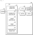
FIG. 1 is a block diagram for explaining the configuration of an entire system of the present invention according to an embodiment of the present invention. -
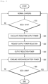
FIG. 2 is a flowchart schematically illustrating a method for preventing overcharging of a battery according to an embodiment of the present invention. - Hereinafter, with reference to the accompanying drawings, an embodiment of the present invention will be described in detail. However, the present invention is not limited to the embodiments disclosed below, and will be implemented in various different forms. Only the embodiments of the present invention are provided to complete the disclosure of the present invention, and to completely inform those of ordinary skill in the art the scope of the invention. In order to explain the embodiment of the present invention, the drawings may be exaggerated, parts irrelevant to the description may be omitted from the drawings, and the same reference numerals in the drawings refer to the same elements.
- Hereinafter, embodiments of the present invention will be described with reference to the drawings.
- Referring to
FIG. 1 , the present invention includes anelectric vehicle 200 including a Vehicle Control Unit (VCU), an E-PTO, and a battery, and acharger 100 for supplying electric energy to theelectric vehicle 200. - A
battery 240 stores electric energy received from theexternal charger 100 and supplies the stored electric energy to themotor 241 while driving. Thebattery 240 of the present invention serves to supply power not only to the drivingmotor 241 but also to the E-PTO 230. - The
motor 241 receives electric energy from thebattery 241 and outputs the received electric energy as driving power of theelectric vehicle 200. - The E-PTO 230 receives electric energy from the
external charger 100 or thebattery 240 and outputs the power required to drive the external electronic equipment of theelectric vehicle 200. - The
electronic equipment 231 is mounted on theelectric vehicle 200 and receives power output from the E-PTO 230 to perform functions other than driving, and for example, includes variouselectronic equipment 231 such as a refrigerator for a refrigeration tower vehicle, a water pump for firefighting, a driving device for opening and closing a wing body, and a lifting device for high-place work. - The Vehicle Control Unit (VCU) 210 controls the power between the
charger 100, thebattery 240, and theE-PTO 230 in theelectric vehicle 200, calculates the power input for a predetermined unit time supplied to thebattery 240 in the overcharging state through theovercharge control unit 220 and the input power to be reduced based on this, and transmits this to thecharger 100 to request a reduction in charging power. - The
overcharge control unit 220 is configured to include a chargingstate detection unit 221, acurrent detection unit 222, apower calculation unit 223, and a powerreduction request unit 224, and may be a component of a Battery Management System (BMS) designed integrally with thebattery 240 or a component of theVCU 210. - The charging
state detection unit 221 detects the overcharging state of thebattery 240 by checking the charging state of thebattery 240, that is, the SOC of thebattery 240 in real time. It is determined that the overcharging state of thebattery 240 exceeds a predetermined SOC upper limit value, for example, 101%. - The
battery 240 SOC upper limit value may be set variously according to system requirements, and for example, the SOC exceeding 100% of thebattery 240 fully charged SOC may be set as the upper limit of the charging capacity. The lower limit charging capacity may be set to less than 100%. - Even when the
battery 240 is in a fully charged state, that is, when the SOC measurement value of thebattery 240 is greater than or equal to a predetermined reference value, for example, greater than or equal to 101%, thecurrent detection unit 222 detects a current value input to thebattery 240. - The detected input current value is a current continuously flowing into the
battery 240 even though thebattery 240 is above a predetermined reference SOC value, so it is determined as an overcharging current, and input current values for a predetermined time period are detected in order to calculate the input overcharge power amount, and at this time, the voltage applied to thebattery 240 is measured together and transmitted to thepower calculation unit 223. - The
power calculation unit 223 calculates the average input power, that is, the amount of overcharge power, for a predetermined time period detected by using the overcharge input current input to thebattery 240 in the overcharging state and the voltage at this time. Also, the reduction power to request reduction from thecharger 100 is calculated based on the calculated average input power. - At this time, even though the SOC of the
battery 240 is, for example, 101% or more, thebattery 240 is in an overcharging state due to excessive power input for the predetermined time period, in order to return this to a normal state, overcharge power of thebattery 240 must be consumed. In the present invention, the power output from thecharger 100 is distributed and supplied to theE-PTO 230 and thebattery 240, and as a method for consuming the power of thebattery 240, theE-PTO 230 requests the charger to output a power smaller than the required power by requesting a reduction in the charging power output from thecharger 100. As a result, all of the reduced charging power output smaller than the required power of theE-PTO 230 is supplied to theE-PTO 230, and in addition, the power insufficient in the required power of theE-PTO 230 required by theE-PTO 230 is inputted from thebattery 240 to theE-PTO 230 and supplied, so that thebattery 240 in the overcharging state consumes power. - On the other hand, the reduction output power requested by the
charger 100 may be calculated by subtracting a greater power from the required power of theE-PTO 230 as the reduction output power, not just the overcharge power that is the average input power input to theovercharge battery 240. For example, the reduction charging power that requests output from the charger may be calculated as power obtained by subtracting twice the average input power (overcharge power) of the overchargingstate battery 240 from the required power of theE-PTO 230. Depending on the system requirements, it is possible to request to reduce the power obtained by subtracting a multiple of 1 or more instead of 2. - The power
reduction request unit 224 transmits to thecharger 100 the power that the calculated reduction output power is reduced to output the reduction charging power. In addition, when the SOC of thebattery 240 detected by the chargingstate detection unit 221 is detected to be less than or equal to a predetermined value, for example, 99%, the reduction output request is stopped and a normal charging is requested. - The
charger 100 is connected to theelectric vehicle 200 and receives and outputs a reduction output or a normal output request according to the SOC state of thebattery 240 detected by theovercharge control unit 220 of theVCU 210. For example, when the SOC is 101% or more, the reduction charging power that reduces the calculated reduction output power is output to prevent overcharging, and at 99% or less, normal power is output, and thebattery 240 SOC may be maintained close to 100%. -
FIG. 2 is a flowchart illustrating a method for preventing overcharging of thebattery 240 of theelectric vehicle 200 according to an embodiment of the present invention. - Each procedure is described as follows.
- First, the
battery 240 is charged by connecting thecharger 100 and theelectric vehicle 200. - The overcharge detection step is a procedure for detecting a state in which the battery is overcharged and continuously detecting a charging current flowing into the battery in the overcharging state.
- This may be configured including an overcharging state checking step and an overcharging current input detection step.
- During charging, the
current detection unit 222 of theovercharge control unit 220 checks the charging state of thebattery 240 , that is, the SOC of thebattery 240 in real time to confirm the charging state. - As a result of checking the charging state, if the SOC is greater than a predetermined SOC upper limit value, for example, 101% or more, it is determined as an overcharging state.
- The overcharging current input detection step is a step of detecting and measuring an overcharging current input in which a charging current is continuously input to the battery even in an overcharging state as a result of checking in the overcharging state checking step.
- When the SOC of the
battery 240 exceeds a predetermined upper limit value, for example, 101% or more, thecurrent detection unit 222 detects the current input to thebattery 240 at this time. Since the detected input current value is a current continuously flowing into thebattery 240 even though thebattery 240 is above a predetermined reference SOC, it is determined as an overcharging current, and in order to calculate the input amount of overcharge power, the input current values are detected for a predetermined time period and at this time, the voltage applied to thebattery 240 is measured together and transmitted to thepower calculation unit 223. - The
battery 240 SOC upper limit value may be set variously according to system requirements, and for example, the SOC exceeding 100 of thebattery 240 fully charged SOC may be set as the upper limit charging capacity. The lower limit charging capacity may be set to less than 100%. - Using the measured overcharge input current and the voltage at this time, the average input power during the detected predetermined time period, that is, the amount of overcharge power is calculated. Also, based on the calculated average input power, a reduction output power (power cutoff amount) to request a reduction from the
charger 100 is calculated. - At this time, since the
battery 240 is in an overcharging state due to excessive power input for the predetermined time period even through the SOC of thebattery 240 is 100%, in order to return this to a normal state, the overcharge power of thebattery 240 must be consumed. The power output from thecharger 100 is distributed and supplied to theE-PTO 230 and thebattery 240, and as a method for consuming power of thebattery 240, the power output from thecharger 100 is output with a power smaller than the power required by theE-PTO 230. As a result, the power output from thecharger 100 is distributed and supplied to theE-PTO 230 and thebattery 240, and as a method for consuming power of thebattery 240, the power output from thecharger 100 is output with a power smaller than the power required by theE-PTO 230. - Therefore, the reduced charging power requested by the
charger 100 is calculated by subtracting the larger power from the reduction output power, not just the average input power of theovercharge battery 240 under theE-PTO 230 requirement. For example, the reduction charging power requested by the charger may be calculated by subtracting twice the average input power of thebattery 240 from the required power of theE-PTO 230. Depending on the system requirements, it may be possible to request a reduction in multiples of 1 or more instead of 2 or more. - The power
reduction request unit 224 requests thecharger 100 to output the reduction charging power obtained by reducing the calculated reduction output power from the required power of theE-PTO 230. In addition, when the SOC of thebattery 240 detected by the chargingstate detection unit 221 is detected as a predetermined lower limit value, for example, 99% or less, it is possible to stop requesting charging power reduction and request normal charging. - The
charger 100 outputs the reduction charging power requested by the powerreduction request unit 224. In addition, when the SOC of thebattery 240 detected by the chargingstate detection unit 221 is detected as a predetermined lower limit value, for example, 99% or less, it is possible to output the normal power by interrupting the reduction output request. - The reduction power input from the
charger 100 receiving the reduction output request to theelectric vehicle 200 is input only to theE-PTO 230 by the power required by theE-PTO 230. Therefore, since thebattery 240 is no longer overcharged and thecharger 100 does not transmit all of the power required by theE-PTO 230, theE-PTO 230 is supplied with insufficient power from thebattery 240, and due to this, the overcharged battery consumes power to be out of the overcharging state. - If the reduction charging power output step continues in the overcharging state of the
battery 240, the SOC is reduced due to power consumption of thebattery 240, and when the SOC of thebattery 240 is confirmed as a predetermined lower limit value, for example, 99% or less, normal charging is performed by stopping the charge power reduction request transmitted from theVCU 210 to thecharger 100. - The system and charging method of the present invention periodically repeat the above process according to the charging state of the
battery 240. As a result, thebattery 240 may prevent overcharging by maintaining the SOC state of a predetermined lower limit value or upper limit value, for example, 99% to 101%, and it will be kept close to the full charging state. - The above embodiments of the present invention are intended to illustrate the present invention, not to limit the present invention. It should be noted that the configurations and methods disclosed in the above embodiments of the present invention may be combined and modified in various forms by combining or intersecting with each other, and modifications thereof may also be considered within the scope of the present invention. That is, the present invention will be implemented in a variety of different forms within the scope of the claims and equivalent technical spirit, and those skilled in the art to which the present invention pertains will understand that various embodiments are possible within the scope of the technical spirit of the present invention.
- Description of Reference Numerals in the drawings of the present invention is given below.
- 100:
- charger
- 200:
- electric vehicle
- 210:
- VCU
- 220:
- overcharge control unit
- 221:
- charging state detection unit
- 222:
- current detection unit
- 223:
- power calculation unit
- 224:
- power reduction request unit
- 230:
- Electric Power Take Off
- 231:
- electronic equipment
- 240:
- battery
- 241:
- motor
Claims (9)
- A method of preventing overcharging of an electric vehicle battery configured to supply electric power to a driving motor of the electric vehicle and an E-PTO, the method comprising:an overcharge detection step of detecting overcharge of the battery;a reduction output power calculation step of calculating an average input power input to the battery in an overcharging state of the battery, and calculating a power to be reduced and output by a charger based on the calculated average input power; anda charge power reduction request step of requesting a reduction in charging power to the charger based on the calculated reduction output power.
- The method of claim 1, further comprising:a reduction charging power output step in which the charger receiving the output power reduction request outputs the reduced charging power;an overcharge battery power consumption step in which the reduced charging power output in the reduction charging power output step is input only to the E-PTO, and an insufficient power of the E-PTO is supplied from the battery to consume an overcharged battery;a normal power output step in which the charger outputs normal power again when power of the overcharged battery is consumed and a charging state of the battery is not an overcharging state,wherein the reduction charging power output step and the normal power output step are repeated based on a battery charging state.
- The method of claim 1, wherein the overcharge detection step comprises:a charging state checking step of confirming the overcharging state of the battery; andan overcharging current input detection step of detecting and measuring an overcharging current input inputted to the battery when checking overcharging of the battery.
- The method of claim 3, wherein the reduction output power calculation step comprises:an input power calculation step of calculating overcharge power using the detected overcharging current input value;an average input power calculation step of calculating an average input power using the calculated overcharge power and a detection time of the overcharging current input; anda reduction output power calculation step of calculating a reduction output power to request reduction from the charger based on the calculated average input power,wherein the reduction output power is a power greater than the average input power.
- The method of claim 1, wherein the charge power reduction request step is to request the charger to output the reduction charging power obtained by subtracting the calculated reduction output power from the E-PTO requirement power.
- The method of claim 1, wherein the overcharging state is 101% of the full charging state, and the non-overcharging state is set to 99% or less of the full charging state to maintain the charging state of the battery close to 100%.
- A system for preventing overcharging of an electric vehicle battery configured to supply electric power to a driving motor of the electric vehicle and an E-PTO,wherein the electric vehicle comprises:a battery configured to store electric energy supplied from a charger;a motor driven by receiving electric energy from the battery;an E-PTO configured to receive electric energy from the charger or the battery and supply power to electronic equipment that functions other than driving; andan overcharge control unit configured to control power input to the battery and the E-PTO and power output from the charger,wherein the overcharge control unit comprises:a charging state detection unit configured to check a charging state of the battery;a current detection unit configured to detect an input current applied to the battery when the battery is overcharged;a power calculation unit configured to calculate an input power based on the input current, calculate an average input power using the input power and a detection time, and calculate an amount of reduction power that the charger needs to reduce charging power based on the average input power; anda power reduction request unit configured to request the charger to output reduction charging power obtained by subtracting the calculated amount of reduction power from the power required by the E-PTO.
- The system of claim 7, wherein the overcharge control unit is a component of a Battery Management System (BMS) designed integrally with a battery or a component of a Vehicle Control Unit (VCU).
- The system of claim 7, wherein the amount of reduction power calculated by the power calculation unit is an amount of power greater than the average input power.
Applications Claiming Priority (3)
| Application Number | Priority Date | Filing Date | Title |
|---|---|---|---|
| KR20200131717 | 2020-10-13 | ||
| KR1020210130201A KR20220048939A (en) | 2020-10-13 | 2021-09-30 | Method for preventing overcharge of vehicle battery pack |
| PCT/KR2021/014040 WO2022080828A1 (en) | 2020-10-13 | 2021-10-12 | Vehicle battery overcharging prevention system and method |
Publications (2)
| Publication Number | Publication Date |
|---|---|
| EP4169766A1 true EP4169766A1 (en) | 2023-04-26 |
| EP4169766A4 EP4169766A4 (en) | 2024-01-10 |
Family
ID=81208499
Family Applications (1)
| Application Number | Title | Priority Date | Filing Date |
|---|---|---|---|
| EP21880475.5A Pending EP4169766A4 (en) | 2020-10-13 | 2021-10-12 | Vehicle battery overcharging prevention system and method |
Country Status (6)
| Country | Link |
|---|---|
| US (1) | US20230294553A1 (en) |
| EP (1) | EP4169766A4 (en) |
| JP (1) | JP7546750B2 (en) |
| CN (1) | CN115916583B (en) |
| TW (1) | TWI912387B (en) |
| WO (1) | WO2022080828A1 (en) |
Cited By (1)
| Publication number | Priority date | Publication date | Assignee | Title |
|---|---|---|---|---|
| FR3158395A1 (en) * | 2024-01-11 | 2025-07-18 | Stellantis Auto Sas | MOTOR VEHICLE COMPRISING A MEANS FOR COMPENSATING CHARGING CURRENT BELOW AN OVERLOAD THRESHOLD, METHOD AND PROGRAM BASED ON SUCH A VEHICLE |
Families Citing this family (2)
| Publication number | Priority date | Publication date | Assignee | Title |
|---|---|---|---|---|
| CN116674429A (en) * | 2023-05-24 | 2023-09-01 | 中国第一汽车股份有限公司 | Method, device, vehicle and storage medium for preventing overcharge of battery in vehicle |
| CN119944879A (en) * | 2023-11-03 | 2025-05-06 | 动力系统国际公司 | Electrical packaging |
Family Cites Families (20)
| Publication number | Priority date | Publication date | Assignee | Title |
|---|---|---|---|---|
| KR20040024754A (en) * | 2002-09-16 | 2004-03-22 | 삼성전자주식회사 | Battery charging system and charging method |
| JP4962184B2 (en) * | 2007-07-18 | 2012-06-27 | トヨタ自動車株式会社 | Vehicle power supply |
| JP4831179B2 (en) | 2009-02-17 | 2011-12-07 | パナソニック電工株式会社 | Charge control device |
| US9018895B2 (en) * | 2009-04-10 | 2015-04-28 | Toyota Jidosha Kabushiki Kaisha | Motor vehicle and control method thereof |
| JP2011061909A (en) * | 2009-09-07 | 2011-03-24 | Toyota Motor Corp | Electric vehicle |
| JP5821256B2 (en) * | 2010-06-09 | 2015-11-24 | 日産自動車株式会社 | Battery charging system |
| JP5370291B2 (en) * | 2010-07-02 | 2013-12-18 | トヨタ自動車株式会社 | vehicle |
| JP5673470B2 (en) | 2011-09-21 | 2015-02-18 | 三菱自動車工業株式会社 | Charger |
| EP2762346A1 (en) | 2011-09-26 | 2014-08-06 | Toyota Jidosha Kabushiki Kaisha | Battery processing device, vehicle, battery processing method, and battery processing program |
| JP5912758B2 (en) * | 2012-03-29 | 2016-04-27 | 本田技研工業株式会社 | Electric vehicle charging control device |
| CN103660967A (en) * | 2012-09-24 | 2014-03-26 | 通用电气公司 | Mobile transportation equipment with improved energy supplying mechanism and mobile transportation method |
| JP6314442B2 (en) | 2013-11-21 | 2018-04-25 | スズキ株式会社 | In-vehicle device controller |
| KR101490958B1 (en) | 2013-11-26 | 2015-02-06 | 현대자동차 주식회사 | Power line communication apparatus for electric vehicle |
| KR101610507B1 (en) | 2014-09-18 | 2016-04-07 | 현대자동차주식회사 | Apparatus and method for diagnosing degradation of high voltage battery of vehicle |
| KR20170051898A (en) * | 2015-11-03 | 2017-05-12 | 현대자동차주식회사 | Battery overcharge safety system |
| KR102784121B1 (en) * | 2016-12-22 | 2025-03-21 | 엘지이노텍 주식회사 | Power control device and method for electric motor vehicle |
| KR20190062824A (en) | 2017-11-29 | 2019-06-07 | 대우전자부품(주) | Charging apparatus and method for electric vehicle based on EVSE interface |
| TWI729372B (en) * | 2018-03-29 | 2021-06-01 | 英屬開曼群島商睿能創意公司 | Vehicle, vehicle charging system and vehicle charging method |
| JP7272772B2 (en) * | 2018-09-28 | 2023-05-12 | トヨタ自動車株式会社 | In-vehicle control device and charging system |
| EP3920308A4 (en) * | 2019-01-31 | 2023-03-15 | Vehicle Energy Japan Inc. | BATTERY CONTROL DEVICE |
-
2021
- 2021-10-12 JP JP2023501854A patent/JP7546750B2/en active Active
- 2021-10-12 US US18/021,104 patent/US20230294553A1/en active Pending
- 2021-10-12 EP EP21880475.5A patent/EP4169766A4/en active Pending
- 2021-10-12 WO PCT/KR2021/014040 patent/WO2022080828A1/en not_active Ceased
- 2021-10-12 CN CN202180048425.8A patent/CN115916583B/en active Active
- 2021-10-12 TW TW110137796A patent/TWI912387B/en active
Cited By (1)
| Publication number | Priority date | Publication date | Assignee | Title |
|---|---|---|---|---|
| FR3158395A1 (en) * | 2024-01-11 | 2025-07-18 | Stellantis Auto Sas | MOTOR VEHICLE COMPRISING A MEANS FOR COMPENSATING CHARGING CURRENT BELOW AN OVERLOAD THRESHOLD, METHOD AND PROGRAM BASED ON SUCH A VEHICLE |
Also Published As
| Publication number | Publication date |
|---|---|
| CN115916583A (en) | 2023-04-04 |
| TWI912387B (en) | 2026-01-21 |
| US20230294553A1 (en) | 2023-09-21 |
| EP4169766A4 (en) | 2024-01-10 |
| JP2023534022A (en) | 2023-08-07 |
| JP7546750B2 (en) | 2024-09-06 |
| CN115916583B (en) | 2025-10-21 |
| TW202218278A (en) | 2022-05-01 |
| WO2022080828A1 (en) | 2022-04-21 |
Similar Documents
| Publication | Publication Date | Title |
|---|---|---|
| CN101958563B (en) | Control strategy for HV battery equalization charge | |
| US8907622B2 (en) | Vehicle charging system and electrically powered vehicle provided with the same | |
| US9421867B2 (en) | Electric vehicle | |
| US9153989B2 (en) | Power monitoring system and electric vehicle | |
| US7911078B2 (en) | Dual type vehicle power-supply apparatus | |
| US8742718B2 (en) | Charging apparatus for vehicle | |
| CN110861538A (en) | Fuel cell automobile hybrid power control method and system | |
| CN115916583B (en) | Vehicle battery overcharge prevention system and method | |
| CN109703367A (en) | A-battery preventing electric loss method and system after a kind of parking of new energy vehicle | |
| CN116476696A (en) | High-voltage architecture new energy automobile system and control method | |
| KR20120012659A (en) | Electric vehicles and method for battery charging control thereof | |
| KR20100119574A (en) | Charge control circuit, and charging device equipped with charge control circuit, battery pack | |
| CN109941106A (en) | The power-supply system of electric vehicle | |
| CN107128184A (en) | Fuel cell and energy storage battery hybrid vehicle control method and vehicle system | |
| EP2903068B1 (en) | Power control device | |
| CN110920393A (en) | Low-voltage power supply system of electric automobile and low-voltage lithium battery charging and discharging method thereof | |
| CN114559814A (en) | Low-voltage electric power management system of electric automobile | |
| KR20220048939A (en) | Method for preventing overcharge of vehicle battery pack | |
| CN117681728A (en) | Method, device, vehicle and storage medium for power battery overcharge protection | |
| KR102017573B1 (en) | Charging control device of electric vehicle and method thereof | |
| EP4717515A1 (en) | Charging control system | |
| CN217720821U (en) | Vehicle-mounted high-power UPS emergency uninterrupted power supply | |
| CN113276677B (en) | Electrical appliance framework of hydrogen fuel cargo van type medical vehicle | |
| US20250244397A1 (en) | Method for estimating full charge capacity of battery | |
| KR20100063347A (en) | Battery management method of a hybrid car |
Legal Events
| Date | Code | Title | Description |
|---|---|---|---|
| STAA | Information on the status of an ep patent application or granted ep patent |
Free format text: STATUS: THE INTERNATIONAL PUBLICATION HAS BEEN MADE |
|
| PUAI | Public reference made under article 153(3) epc to a published international application that has entered the european phase |
Free format text: ORIGINAL CODE: 0009012 |
|
| STAA | Information on the status of an ep patent application or granted ep patent |
Free format text: STATUS: REQUEST FOR EXAMINATION WAS MADE |
|
| 17P | Request for examination filed |
Effective date: 20230119 |
|
| AK | Designated contracting states |
Kind code of ref document: A1 Designated state(s): AL AT BE BG CH CY CZ DE DK EE ES FI FR GB GR HR HU IE IS IT LI LT LU LV MC MK MT NL NO PL PT RO RS SE SI SK SM TR |
|
| A4 | Supplementary search report drawn up and despatched |
Effective date: 20231208 |
|
| RIC1 | Information provided on ipc code assigned before grant |
Ipc: H01M 10/42 20060101ALI20231204BHEP Ipc: B60L 53/14 20190101ALI20231204BHEP Ipc: B60L 58/13 20190101ALI20231204BHEP Ipc: B60L 1/00 20060101ALI20231204BHEP Ipc: G01R 31/36 20200101ALI20231204BHEP Ipc: B60W 30/188 20120101ALI20231204BHEP Ipc: H02J 7/00 20060101ALI20231204BHEP Ipc: B60L 3/00 20190101ALI20231204BHEP Ipc: B60L 50/60 20190101ALI20231204BHEP Ipc: B60L 53/66 20190101ALI20231204BHEP Ipc: B60L 58/15 20190101AFI20231204BHEP |
|
| DAV | Request for validation of the european patent (deleted) | ||
| DAX | Request for extension of the european patent (deleted) |