EP4169731A1 - A bicycle rim and a method for manufacturing thereof - Google Patents
A bicycle rim and a method for manufacturing thereof Download PDFInfo
- Publication number
- EP4169731A1 EP4169731A1 EP22201070.4A EP22201070A EP4169731A1 EP 4169731 A1 EP4169731 A1 EP 4169731A1 EP 22201070 A EP22201070 A EP 22201070A EP 4169731 A1 EP4169731 A1 EP 4169731A1
- Authority
- EP
- European Patent Office
- Prior art keywords
- rim
- magnetized part
- bicycle
- manufacturing
- anyone
- Prior art date
- Legal status (The legal status is an assumption and is not a legal conclusion. Google has not performed a legal analysis and makes no representation as to the accuracy of the status listed.)
- Granted
Links
Images

Classifications
-
- B—PERFORMING OPERATIONS; TRANSPORTING
- B60—VEHICLES IN GENERAL
- B60B—VEHICLE WHEELS; CASTORS; AXLES FOR WHEELS OR CASTORS; INCREASING WHEEL ADHESION
- B60B21/00—Rims
- B60B21/12—Appurtenances, e.g. lining bands
-
- B—PERFORMING OPERATIONS; TRANSPORTING
- B60—VEHICLES IN GENERAL
- B60B—VEHICLE WHEELS; CASTORS; AXLES FOR WHEELS OR CASTORS; INCREASING WHEEL ADHESION
- B60B1/00—Spoked wheels; Spokes thereof
- B60B1/003—Spoked wheels; Spokes thereof specially adapted for bicycles
-
- G—PHYSICS
- G01—MEASURING; TESTING
- G01P—MEASURING LINEAR OR ANGULAR SPEED, ACCELERATION, DECELERATION, OR SHOCK; INDICATING PRESENCE, ABSENCE, OR DIRECTION, OF MOVEMENT
- G01P3/00—Measuring linear or angular speed; Measuring differences of linear or angular speeds
- G01P3/42—Devices characterised by the use of electric or magnetic means
- G01P3/44—Devices characterised by the use of electric or magnetic means for measuring angular speed
- G01P3/48—Devices characterised by the use of electric or magnetic means for measuring angular speed by measuring frequency of generated current or voltage
- G01P3/481—Devices characterised by the use of electric or magnetic means for measuring angular speed by measuring frequency of generated current or voltage of pulse signals
- G01P3/487—Devices characterised by the use of electric or magnetic means for measuring angular speed by measuring frequency of generated current or voltage of pulse signals delivered by rotating magnets
-
- B—PERFORMING OPERATIONS; TRANSPORTING
- B60—VEHICLES IN GENERAL
- B60B—VEHICLE WHEELS; CASTORS; AXLES FOR WHEELS OR CASTORS; INCREASING WHEEL ADHESION
- B60B2900/00—Purpose of invention
- B60B2900/90—Providing or changing
- B60B2900/931—Magnetic effects
Definitions
- the invention relates to a bicycle rim and a method for manufacturing thereof, wherein such a rim is arranged for enabling measurements of its rotational speed and subsequently enabling measurements of a linear speed of a bicycle of which the bicycle rim forms part.
- WO03/084804 and US2017/0305496 each disclose a bicycle rim comprising at least one magnetized part which is concealably embedded inside the rim.
- DE 10 2015 102 465 discloses manufacturing a rim for a muscle-powered vehicle.
- this document teaches that it is advantageous to insert a (permanent) magnet, a (magnetic) sensor, an RFID chip, a counterweight and/or a valve tube in the rim.
- US2012204639 discloses a bicycle wheel provided with a magnetic speed sensing apparatus for indicating the speed of a bicycle.
- a spoked wheel according to US2012204639 , one of the spokes is fabricated from a magnetic material such that each time that particular spoke passes a sensing apparatus a requisite current impulse is transmitted to a handlebar mounted receiving unit.
- a single spoke fabricated from the same magnetic material as above is affixed to the surface of the disk wheel.
- the bicycle rim comprises at least one magnetized part wherein the at least one magnetized part is concealably embedded inside the rim, wherein the rim preferably comprises at least one joint sleeve and that the at least one magnetized part is embedded in said at least one joint sleeve.
- the rim preferably comprises at least one joint sleeve and that the at least one magnetized part is embedded in said at least one joint sleeve.
- the at least one joint sleeve is shaped according to an internal profile of the rim. And, that the at least one joint sleeve is curved according to a curvature of the rim.
- Metallic rims are usually made by bending a metallic extrusion into a coil, cutting the coil into open hoops and welding the joints of said open hoops resulting in closed hoops.
- Top quality rims manufacturers provide a sleeve to the rim and glue the rim at the joint of the open hoop, wherein the joint sleeve is shaped according to an internal profile of the rim. This technique results in a stronger and safer joint.
- the current invention advantageously proposes to embed a magnetized part in the joint sleeve during the manufacturing process of said rim.
- the rim may comprise at least two joint pins wherein the at least one magnetized part is embedded in an internal space of the rim between the at least two joint pins.
- the internal space of the rim between the two joint pins can advantageously be used for concealing the magnetized part.
- Such embodiment preserves the mechanical structure of the rim all the while discretely providing said rim with the magnetized part needed for speed measurements.
- the at least one magnetized part is a permanent magnet.
- the vast majority of speed sensors detect the motion of ferromagnetic structures, such as permanent magnets, based on the variation in magnetic flow. These variations can be converted into electrical variables and subsequently conditioned into speed measurements.
- the rim comprises an aperture for a valve of a tube mountable on the rim wherein said aperture and the at least one magnetized part are substantially diametrically opposite to each other.
- Such embodiment allows for counterbalancing the weight of the at least one magnetized part with the weight of the valve.
- the rim comprises at least one mass concealably embedded in said rim substantially diametrically opposite to the at least one magnetized part.
- the weight of at least one mass is substantially equal to the mass of the at least one magnetized part.
- a bicycle wheel is provided with the rim according to the first aspect of the invention.
- the method for manufacturing a bicycle rim comprises the steps of
- Such embodiment preserves the mechanical structure of the rim all the while discretely providing said rim with the magnetized part needed for speed measurements.
- This technique results in a stronger and safer rim suitable for speed measurements via magnetic sensors.
- the order of the aforementioned steps may vary according to the requirements of the manufacturing line.
- the at least one magnetized part may be brought inside the joint sleeve before providing the joint sleeve in the open hoop.
- the sleeve may first be embedded in the open hoop before embedding the at least one magnetized part in said joint sleeve.
- said method comprises the steps of:
- the step of closing the open hoop comprises at least one of the following steps:
- Carbon fiber rims are made of two components; carbon fiber and epoxy resin.
- pre-preg carbon fiber are laid into molds.
- Pre-peg is raw carbon fiber that is impregnated with an epoxy resin.
- the pre-preg carbon is laid in the mold, it is placed in an oven where it goes through a prescribed heating cycle know as a ramp cycle.
- the carbon fiber exits the mold it is a hard finished part.
- the method of the invention comprises the steps of:
- the method of the invention may comprise the step of concealably embedding at least one mass in said rim substantially diametrically opposite to the at least one magnetized part, wherein preferably said at least one mass is substantially equal to the mass of the at least one magnetized part.
- Such embodiment allows for an exact counterbalancing of the weight of the at least one magnetized part with the weight of the at least one mass.
- the method of the invention may comprise the step of concealably embedding at least one magnetized part inside said rim substantially diametrically opposite to a valve of the rim.
- Such embodiment allows for counterbalancing the weight of the at least one magnetized part with the weight of the valve.
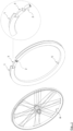
- Figure 1 shows how a magnetized part 2 can be embedded in a joint sleeve 3 which is to be embedded in the rim 1 diametrically opposite to the bicycle wheel's valve 6 and a valve aperture 5 through which the valve 6 is stuck.
- the mass of the magnetized part 2 is preferably substantially counterbalanced by the mass of the valve 6.
- figure 2 shows how the magnetized part 2 can be embedded in an internal space of the rim 1 between two joint pins 4 diametrically opposite the valve 6 and the valve aperture 5.
- the mass of the magnetized part 2 being again substantially counterbalanced by the mass of the valve 6.
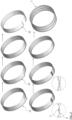
- Figure 5 shows the steps involved in manufacturing the bicycle rim 1.
- a metallic extrusion is bent into a coil 11, then the coil 11 is cut into open hoops 12.
- the at least two joint pins 4 and the at least one magnetized 2 part are embedded inside the rim 1, then the open hoops 12 are closed.
- the same process is used when in the embodiment of fig. 1 the at least one joint sleeve 3 and the at least one magnetized part is embedded inside the rim 1.
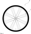
- Figure 3 shows the wheel 8 comprising a rim 1 according to the invention. It is understood that a wheel is a rim combined with a tire and/or a tube.
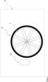
- Figure 4 shows the assembly 9 of the wheel 8 and an electromagnetic sensor 10.
- the electromagnetic sensor being placed in a proximity of the wheel 8 for picking up an electromagnetic signal triggered by the movement of the magnetized part 2. Said electromagnetic signal is indicative for the bicycle speed.
Landscapes
- Engineering & Computer Science (AREA)
- Mechanical Engineering (AREA)
- Physics & Mathematics (AREA)
- General Physics & Mathematics (AREA)
- Tires In General (AREA)
- Tyre Moulding (AREA)
Abstract
Description
- The invention relates to a bicycle rim and a method for manufacturing thereof, wherein such a rim is arranged for enabling measurements of its rotational speed and subsequently enabling measurements of a linear speed of a bicycle of which the bicycle rim forms part.
- In the current disclosure, when the term "bicycle" is used, it will be understood by those skilled in the art that this term is intended to be generic and is meant to include unicycles, tricycles, quadricycles and other forms of wheeled, human powered vehicles such as recumbent cycles, wheelchairs, baby stroller joggers and child carts attached to bicycles, but also E-bikes E-scooters and Rollers. The term "bicycle" is therefore not limiting.
-
WO03/084804 US2017/0305496 each disclose a bicycle rim comprising at least one magnetized part which is concealably embedded inside the rim. -
DE 10 2015 102 465 discloses manufacturing a rim for a muscle-powered vehicle. In order to enable good speed determination or cadence determination, this document teaches that it is advantageous to insert a (permanent) magnet, a (magnetic) sensor, an RFID chip, a counterweight and/or a valve tube in the rim. -
US2012204639 discloses a bicycle wheel provided with a magnetic speed sensing apparatus for indicating the speed of a bicycle. In a spoked wheel according toUS2012204639 , one of the spokes is fabricated from a magnetic material such that each time that particular spoke passes a sensing apparatus a requisite current impulse is transmitted to a handlebar mounted receiving unit. When the bicycle is provided with a disk wheel, a single spoke fabricated from the same magnetic material as above is affixed to the surface of the disk wheel. - An obvious drawback of the bicycle wheel of
US2012204639 is the risk of fragilizing the structure of the bicycle wheel by replacing one of the spokes by a spoke made from a magnetic material. Another drawback of this prior art bicycle wheel is that the magnetic material would be visible in the application when the magnetic spoke is fixed on the disk wheel. An additional disadvantage is that the replacement of one spoke brings about extra handling during wheel assembly. - It is an object of the current invention to correct the shortcomings of the prior art and to provide cyclists with an alternative option of a bicycle rim arranged for enabling measurements of the bicycle speed.
- This and other objects which will become apparent from the following disclosure, are provided with a bicycle rim, a bicycle wheel, and a method of manufacturing a bicycle rim having the features of one or more of the appended claims.
- According to a first aspect of the invention the bicycle rim comprises at least one magnetized part wherein the at least one magnetized part is concealably embedded inside the rim, wherein the rim preferably comprises at least one joint sleeve and that the at least one magnetized part is embedded in said at least one joint sleeve. Such embodiment according to the invention preserves the mechanical structure of the rim all the while discretely providing said rim with the magnetized part needed for speed measurements.
- Furthermore, it is preferable that the at least one joint sleeve is shaped according to an internal profile of the rim. And, that the at least one joint sleeve is curved according to a curvature of the rim. These features ensure that the at least one sleeve is tightly fitted inside the rim.
- Metallic rims are usually made by bending a metallic extrusion into a coil, cutting the coil into open hoops and welding the joints of said open hoops resulting in closed hoops. Top quality rims manufacturers provide a sleeve to the rim and glue the rim at the joint of the open hoop, wherein the joint sleeve is shaped according to an internal profile of the rim. This technique results in a stronger and safer joint. The current invention advantageously proposes to embed a magnetized part in the joint sleeve during the manufacturing process of said rim.
- According to a further aspect of the invention, the rim may comprise at least two joint pins wherein the at least one magnetized part is embedded in an internal space of the rim between the at least two joint pins. The internal space of the rim between the two joint pins can advantageously be used for concealing the magnetized part. Such embodiment preserves the mechanical structure of the rim all the while discretely providing said rim with the magnetized part needed for speed measurements.
- Advantageously, the at least one magnetized part is a permanent magnet. The vast majority of speed sensors detect the motion of ferromagnetic structures, such as permanent magnets, based on the variation in magnetic flow. These variations can be converted into electrical variables and subsequently conditioned into speed measurements.
- Embedding a magnetized part in the rim could disturb the rotational balance of the rim. In order to solve such issue, the rim comprises an aperture for a valve of a tube mountable on the rim wherein said aperture and the at least one magnetized part are substantially diametrically opposite to each other. Such embodiment allows for counterbalancing the weight of the at least one magnetized part with the weight of the valve.
- Furthermore, it may be preferable that the rim comprises at least one mass concealably embedded in said rim substantially diametrically opposite to the at least one magnetized part. Suitably, the weight of at least one mass is substantially equal to the mass of the at least one magnetized part.
Such embodiment allows for exact counterbalancing the weight of the at least one magnetized part with the weight of the at least one mass. - According to a second aspect of the invention, a bicycle wheel is provided with the rim according to the first aspect of the invention.
- According to a third aspect of the invention, the method for manufacturing a bicycle rim comprises the steps of
- bending a metallic extrusion into a coil;
- cutting the coil into open hoops
- providing at least one joint sleeve inside at least one end of an open hoop; and
- closing the open hoop,
- Such embodiment preserves the mechanical structure of the rim all the while discretely providing said rim with the magnetized part needed for speed measurements. This technique results in a stronger and safer rim suitable for speed measurements via magnetic sensors. The order of the aforementioned steps may vary according to the requirements of the manufacturing line. In a semi-automated manufacturing line the at least one magnetized part may be brought inside the joint sleeve before providing the joint sleeve in the open hoop. In a fully-automated manufacturing line, the sleeve may first be embedded in the open hoop before embedding the at least one magnetized part in said joint sleeve.
- Alternatively, said method comprises the steps of:
- bending a metallic extrusion into a coil;
- cutting the coil into open hoops
- providing at least two joint pins inside at least one end of an open hoop; and
- closing the open hoop,
- Depending on the type of the rim and the requirements of the manufacturing line, the step of closing the open hoop comprises at least one of the following steps:
- gluing the open hoop;
- riveting the open hoop;
- welding the open hoop; and
- mechanically securing by pressing the open hoop.
- It is also possible to apply the invention with carbon fiber rims. Carbon fiber rims are made of two components; carbon fiber and epoxy resin. When molding a carbon fiber wheel, pieces of pre-preg carbon fiber are laid into molds. Pre-peg is raw carbon fiber that is impregnated with an epoxy resin. Once the pre-preg carbon is laid in the mold, it is placed in an oven where it goes through a prescribed heating cycle know as a ramp cycle. When the carbon fiber exits the mold, it is a hard finished part.
When the rim is made of carbon fiber material, the method of the invention comprises the steps of: - providing raw carbon fibers in a hoop shaped mold; and
- hardening said raw carbon fiber inside an oven,
- Furthermore, the method of the invention may comprise the step of concealably embedding at least one mass in said rim substantially diametrically opposite to the at least one magnetized part, wherein preferably said at least one mass is substantially equal to the mass of the at least one magnetized part. Such embodiment allows for an exact counterbalancing of the weight of the at least one magnetized part with the weight of the at least one mass.
- Advantageously, the method of the invention may comprise the step of concealably embedding at least one magnetized part inside said rim substantially diametrically opposite to a valve of the rim. Such embodiment allows for counterbalancing the weight of the at least one magnetized part with the weight of the valve.
- The invention will hereinafter be further elucidated with reference to the drawing of an exemplary embodiment of a bicycle rim, a bicycle wheel and an assembly according to the invention that is not limiting as to the appended claims.
- In the drawing:
-
figure 1 shows a first embodiment of a bicycle rim of the invention in an exploded view; -
figure 2 shows a second embodiment of a bicycle rim of the invention in an exploded view; -
figure 3 shows a wheel of the invention in a side view; -
figure 4 shows an assembly of the invention in a front view; and -
figure 5 shows the manufacturing steps of a rim according to the invention. - Whenever in the figures the same reference numerals are applied, these numerals refer to the same parts.
-
Figure 1 shows how amagnetized part 2 can be embedded in ajoint sleeve 3 which is to be embedded in therim 1 diametrically opposite to the bicycle wheel'svalve 6 and avalve aperture 5 through which thevalve 6 is stuck. The mass of themagnetized part 2 is preferably substantially counterbalanced by the mass of thevalve 6. Equally,figure 2 shows how themagnetized part 2 can be embedded in an internal space of therim 1 between twojoint pins 4 diametrically opposite thevalve 6 and thevalve aperture 5. The mass of themagnetized part 2 being again substantially counterbalanced by the mass of thevalve 6. -
Figure 5 shows the steps involved in manufacturing thebicycle rim 1. A metallic extrusion is bent into acoil 11, then thecoil 11 is cut intoopen hoops 12. Next, according to the embodiment offig. 2 , the at least twojoint pins 4 and the at least one magnetized 2 part are embedded inside therim 1, then theopen hoops 12 are closed. The same process is used when in the embodiment offig. 1 the at least onejoint sleeve 3 and the at least one magnetized part is embedded inside therim 1. -
Figure 3 shows thewheel 8 comprising arim 1 according to the invention. It is understood that a wheel is a rim combined with a tire and/or a tube. -
Figure 4 shows theassembly 9 of thewheel 8 and anelectromagnetic sensor 10. The electromagnetic sensor being placed in a proximity of thewheel 8 for picking up an electromagnetic signal triggered by the movement of themagnetized part 2. Said electromagnetic signal is indicative for the bicycle speed. - Although the invention has been discussed in the foregoing with reference to an exemplary embodiment of a rim, a bicycle wheel and a method of manufacturing according to the invention, the invention is not restricted to this particular embodiment which can be varied in many ways without departing from the invention. The discussed exemplary embodiment shall therefore not be used to construe the appended claims strictly in accordance therewith. On the contrary the embodiment is merely intended to explain the wording of the appended claims without intent to limit the claims to this exemplary embodiment. The scope of protection of the invention shall therefore be construed in accordance with the appended claims only, wherein a possible ambiguity in the wording of the claims shall be resolved using this exemplary embodiment.
Claims (15)
- A bicycle rim (1) comprising at least one magnetized part (2) which is concealably embedded inside the rim (1), characterized in that said rim (1) comprises at least one joint sleeve (3) and the at least one magnetized part (2) is embedded in said at least one joint sleeve (3).
- The rim (1) according to claim 1, characterized in that the at least one joint sleeve (3) is shaped according to an internal profile of the rim (1).
- The rim (1) according to claim 1 or 2, characterized in that the at least one joint sleeve (3) is curved according to a curvature of the rim (1).
- The rim (1) according to anyone of claims 1 - 3, characterized in that the rim (1) comprises at least two joint pins (4) wherein the at least one magnetized part (2) is embedded in an internal space of the rim (1) between the at least two joint pins (4).
- The rim (1) according to anyone of claims 1 - 4, characterized in that the at least one magnetized part (2) is a permanent magnet.
- The rim (1) according to anyone of claims 1 - 5, wherein said rim (1) comprises an aperture (5) for a valve (6) of a tube mountable on the rim (1), characterized in that said aperture (5) and the at least one magnetized part (2) are substantially diametrically opposite to each other.
- The rim (1) according to anyone of claims 1 - 6, characterized in that the rim (1) comprises at least one mass (7) concealably embedded in said rim (1) substantially diametrically opposite to the at least one magnetized part (2).
- The rim (1) according to claim 7, characterized in that the weight of at least one mass (7) is substantially equal to the mass of the at least one magnetized part (2).
- A bicycle wheel (8), characterized in that said wheel (8) is provided with the rim (1) according to anyone of claims 1 - 8.
- A method for manufacturing a bicycle rim (1), comprising the steps of:- bending a metallic extrusion into a coil (11);- cutting the coil into open hoops (12);- providing at least one joint sleeve (3) inside at least one end of an open hoop (12); and- closing the open hoop (12),characterized in that said method comprises the step of embedding the at least one magnetized part (2) in the at least one joint sleeve (3).
- The method for manufacturing a bicycle rim (1) according to claim 10, comprising the steps of:- providing at least two joint pins (4) inside at least one end of an open hoop (12); and
characterized in that said method comprises the step of embedding the at least one magnetized part (2) in an internal space of the metallic extrusion between said at least two joint pins (4). - The method for manufacturing a bicycle rim (1) according to anyone of claims 10-11, characterized in that the step of closing the open hoop (12) comprises at least one of the following steps:- gluing the open hoop (12);- riveting the open hoop (12);- welding the open hoop (12); and- mechanically securing by pressing the open hoop (12).
- The method for manufacturing a bicycle rim (1) according to claim 10, comprising the steps of:- providing raw carbon fibers in a hoop shaped mold; and- hardening said raw carbon fiber inside an oven, characterized in that said method comprises the step of providing at least one magnetized part (2) in said raw carbon fibers.
- The method for manufacturing a bicycle rim (1) according to anyone of claims 10-13, characterized in that said method comprises the step of concealably embedding at least one mass in said rim (1) substantially diametrically opposite to the at least one magnetized part (2), wherein preferably said at least one mass is substantially equal to the mass of the at least one magnetized part (2).
- The method for manufacturing a bicycle rim (1) according to anyone of claims 10-14, characterized in that said method comprises the step of concealably embedding at least one magnetized part (2) inside said rim (1) substantially diametrically opposite to a valve (6) of the rim (1).
Applications Claiming Priority (1)
| Application Number | Priority Date | Filing Date | Title |
|---|---|---|---|
| NL2029483A NL2029483B1 (en) | 2021-10-21 | 2021-10-21 | A bicycle rim and a method for manufacturing thereof |
Publications (3)
| Publication Number | Publication Date |
|---|---|
| EP4169731A1 true EP4169731A1 (en) | 2023-04-26 |
| EP4169731C0 EP4169731C0 (en) | 2025-04-09 |
| EP4169731B1 EP4169731B1 (en) | 2025-04-09 |
Family
ID=79018816
Family Applications (1)
| Application Number | Title | Priority Date | Filing Date |
|---|---|---|---|
| EP22201070.4A Active EP4169731B1 (en) | 2021-10-21 | 2022-10-12 | A bicycle rim and a method for manufacturing thereof |
Country Status (5)
| Country | Link |
|---|---|
| EP (1) | EP4169731B1 (en) |
| CN (1) | CN116001485A (en) |
| HU (1) | HUE071903T2 (en) |
| NL (1) | NL2029483B1 (en) |
| TW (1) | TWI852137B (en) |
Citations (6)
| Publication number | Priority date | Publication date | Assignee | Title |
|---|---|---|---|---|
| DE20180376U1 (en) * | 2000-11-14 | 2003-07-17 | Mavic S.A., Saint-Trivier Sur Moignans | Bicycle rim intended for tubeless mounting |
| WO2003084804A1 (en) | 2002-04-09 | 2003-10-16 | Glow S.R.L. | Rim structure particularly for cycle wheel with variable magnetic field electric generator |
| US20120204639A1 (en) | 2011-02-15 | 2012-08-16 | Chris Mogridge | Magnetic rotation sensor |
| DE102015102465A1 (en) | 2015-02-20 | 2016-08-25 | Carbofibretec Gmbh | Method for producing a rim ring, method for fixing spokes, rim, in particular clincher rim and bicycle |
| US20170305496A1 (en) | 2015-02-25 | 2017-10-26 | Ford Global Technologies, Llc | Wheel rim-mounted regeneration coil-magnet system |
| EP3476621A1 (en) * | 2017-10-27 | 2019-05-01 | Ambrosio S.r.l. Dei F.lli Marzorati | Joining element for bicycle rims and bicycle rim incorporating such a joining element |
Family Cites Families (5)
| Publication number | Priority date | Publication date | Assignee | Title |
|---|---|---|---|---|
| TWI272196B (en) * | 2005-09-26 | 2007-02-01 | Alex Global Technology Inc | Wheel rim with hollow embedded flanges |
| CN201999119U (en) * | 2010-08-27 | 2011-10-05 | 六毅科技股份有限公司 | Induction magnet buckling seat of bicycle |
| TWI627056B (en) * | 2015-02-20 | 2018-06-21 | 嘉寶費博萊特克有限公司 | Method for the manufacturing of a rim,the rim so manufactured,a running wheel including the rim and a bicycle having the running wheel |
| TWI603858B (en) * | 2016-11-22 | 2017-11-01 | Gigantex Composite Technologiesco Ltd | A core-stock material, a core-molding device, and a method of manufacturing the composite rim using the core-type device |
| TWM610625U (en) * | 2020-08-20 | 2021-04-21 | 黃玉山 | Combination structure of wheel rim |
-
2021
- 2021-10-21 NL NL2029483A patent/NL2029483B1/en active
-
2022
- 2022-10-12 HU HUE22201070A patent/HUE071903T2/en unknown
- 2022-10-12 EP EP22201070.4A patent/EP4169731B1/en active Active
- 2022-10-18 CN CN202211271409.8A patent/CN116001485A/en active Pending
- 2022-10-21 TW TW111140138A patent/TWI852137B/en active
Patent Citations (6)
| Publication number | Priority date | Publication date | Assignee | Title |
|---|---|---|---|---|
| DE20180376U1 (en) * | 2000-11-14 | 2003-07-17 | Mavic S.A., Saint-Trivier Sur Moignans | Bicycle rim intended for tubeless mounting |
| WO2003084804A1 (en) | 2002-04-09 | 2003-10-16 | Glow S.R.L. | Rim structure particularly for cycle wheel with variable magnetic field electric generator |
| US20120204639A1 (en) | 2011-02-15 | 2012-08-16 | Chris Mogridge | Magnetic rotation sensor |
| DE102015102465A1 (en) | 2015-02-20 | 2016-08-25 | Carbofibretec Gmbh | Method for producing a rim ring, method for fixing spokes, rim, in particular clincher rim and bicycle |
| US20170305496A1 (en) | 2015-02-25 | 2017-10-26 | Ford Global Technologies, Llc | Wheel rim-mounted regeneration coil-magnet system |
| EP3476621A1 (en) * | 2017-10-27 | 2019-05-01 | Ambrosio S.r.l. Dei F.lli Marzorati | Joining element for bicycle rims and bicycle rim incorporating such a joining element |
Also Published As
| Publication number | Publication date |
|---|---|
| TWI852137B (en) | 2024-08-11 |
| CN116001485A (en) | 2023-04-25 |
| EP4169731C0 (en) | 2025-04-09 |
| NL2029483B1 (en) | 2023-05-16 |
| HUE071903T2 (en) | 2025-10-28 |
| TW202330303A (en) | 2023-08-01 |
| EP4169731B1 (en) | 2025-04-09 |
Similar Documents
| Publication | Publication Date | Title |
|---|---|---|
| US20080252038A1 (en) | Bicycle frame with device cavity | |
| US20160243732A1 (en) | Method for the manufacturing of a rim ring, method for the fixing of spokes, rim, in particular clincher-rim, and bicycle | |
| US6279419B1 (en) | Steering wheel | |
| EP4169731B1 (en) | A bicycle rim and a method for manufacturing thereof | |
| US20160243893A1 (en) | Machine-made reinforcing fiber rim for a vehicle and method of manufacturing said rim | |
| US10209149B2 (en) | Installation method and an apparatus of a sensor based on strain gauges to generate deformation signals caused by an applied force | |
| TWI627056B (en) | Method for the manufacturing of a rim,the rim so manufactured,a running wheel including the rim and a bicycle having the running wheel | |
| EP0795456A3 (en) | Steering wheel and method of manufacture | |
| CN109311343B (en) | Integral injection molded wheel with high stability | |
| US9604499B2 (en) | Compression molded hub shell | |
| US10717323B2 (en) | Sensing part, sensing unit, wheel speed sensing device and vehicle | |
| US20070029868A1 (en) | Wheel rim for cycling device | |
| US9403404B2 (en) | Carbon fiber rim and method of manufacturing the same | |
| WO2014061002A1 (en) | Motor vehicle rim made of a composite material and relative manufacturing method | |
| US20070108724A1 (en) | Bicycle frame | |
| US9751582B2 (en) | Bicycle assembly with bottom bracket area | |
| US20120204639A1 (en) | Magnetic rotation sensor | |
| KR20160003491U (en) | Wheel speed sensor device, sensor unit thereof, and vehicle using the wheel speed sensor device | |
| CN211391576U (en) | Rear bottom fork of wheel type power vehicle | |
| CN211032897U (en) | Anti-collision silica gel handle | |
| US20100199498A1 (en) | Process of making base of shock-absorbing front fork for bicycle | |
| TWI532606B (en) | Carbon fiber rim and its making method | |
| WO2011016622A3 (en) | Night-time visibility device for bicycles | |
| CN110682989A (en) | Wheeled power vehicle rear flat fork and manufacturing method thereof | |
| CN208392675U (en) | A kind of assembly mold of carbon fibre rim and brake side |
Legal Events
| Date | Code | Title | Description |
|---|---|---|---|
| PUAI | Public reference made under article 153(3) epc to a published international application that has entered the european phase |
Free format text: ORIGINAL CODE: 0009012 |
|
| STAA | Information on the status of an ep patent application or granted ep patent |
Free format text: STATUS: THE APPLICATION HAS BEEN PUBLISHED |
|
| AK | Designated contracting states |
Kind code of ref document: A1 Designated state(s): AL AT BE BG CH CY CZ DE DK EE ES FI FR GB GR HR HU IE IS IT LI LT LU LV MC ME MK MT NL NO PL PT RO RS SE SI SK SM TR |
|
| STAA | Information on the status of an ep patent application or granted ep patent |
Free format text: STATUS: REQUEST FOR EXAMINATION WAS MADE |
|
| 17P | Request for examination filed |
Effective date: 20231026 |
|
| RBV | Designated contracting states (corrected) |
Designated state(s): AL AT BE BG CH CY CZ DE DK EE ES FI FR GB GR HR HU IE IS IT LI LT LU LV MC ME MK MT NL NO PL PT RO RS SE SI SK SM TR |
|
| RIC1 | Information provided on ipc code assigned before grant |
Ipc: G01P 3/487 20060101ALI20240927BHEP Ipc: B60B 21/12 20060101ALI20240927BHEP Ipc: B60B 1/00 20060101AFI20240927BHEP |
|
| GRAP | Despatch of communication of intention to grant a patent |
Free format text: ORIGINAL CODE: EPIDOSNIGR1 |
|
| STAA | Information on the status of an ep patent application or granted ep patent |
Free format text: STATUS: GRANT OF PATENT IS INTENDED |
|
| INTG | Intention to grant announced |
Effective date: 20241114 |
|
| GRAS | Grant fee paid |
Free format text: ORIGINAL CODE: EPIDOSNIGR3 |
|
| GRAA | (expected) grant |
Free format text: ORIGINAL CODE: 0009210 |
|
| STAA | Information on the status of an ep patent application or granted ep patent |
Free format text: STATUS: THE PATENT HAS BEEN GRANTED |
|
| AK | Designated contracting states |
Kind code of ref document: B1 Designated state(s): AL AT BE BG CH CY CZ DE DK EE ES FI FR GB GR HR HU IE IS IT LI LT LU LV MC ME MK MT NL NO PL PT RO RS SE SI SK SM TR |
|
| REG | Reference to a national code |
Ref country code: GB Ref legal event code: FG4D |
|
| REG | Reference to a national code |
Ref country code: CH Ref legal event code: EP |
|
| REG | Reference to a national code |
Ref country code: IE Ref legal event code: FG4D |
|
| U01 | Request for unitary effect filed |
Effective date: 20250409 |
|
| U07 | Unitary effect registered |
Designated state(s): AT BE BG DE DK EE FI FR IT LT LU LV MT NL PT RO SE SI Effective date: 20250415 |
|
| PG25 | Lapsed in a contracting state [announced via postgrant information from national office to epo] |
Ref country code: ES Free format text: LAPSE BECAUSE OF FAILURE TO SUBMIT A TRANSLATION OF THE DESCRIPTION OR TO PAY THE FEE WITHIN THE PRESCRIBED TIME-LIMIT Effective date: 20250409 |
|
| PG25 | Lapsed in a contracting state [announced via postgrant information from national office to epo] |
Ref country code: NO Free format text: LAPSE BECAUSE OF FAILURE TO SUBMIT A TRANSLATION OF THE DESCRIPTION OR TO PAY THE FEE WITHIN THE PRESCRIBED TIME-LIMIT Effective date: 20250709 Ref country code: GR Free format text: LAPSE BECAUSE OF FAILURE TO SUBMIT A TRANSLATION OF THE DESCRIPTION OR TO PAY THE FEE WITHIN THE PRESCRIBED TIME-LIMIT Effective date: 20250710 |
|
| PG25 | Lapsed in a contracting state [announced via postgrant information from national office to epo] |
Ref country code: PL Free format text: LAPSE BECAUSE OF FAILURE TO SUBMIT A TRANSLATION OF THE DESCRIPTION OR TO PAY THE FEE WITHIN THE PRESCRIBED TIME-LIMIT Effective date: 20250409 |
|
| PG25 | Lapsed in a contracting state [announced via postgrant information from national office to epo] |
Ref country code: HR Free format text: LAPSE BECAUSE OF FAILURE TO SUBMIT A TRANSLATION OF THE DESCRIPTION OR TO PAY THE FEE WITHIN THE PRESCRIBED TIME-LIMIT Effective date: 20250409 |
|
| PG25 | Lapsed in a contracting state [announced via postgrant information from national office to epo] |
Ref country code: RS Free format text: LAPSE BECAUSE OF FAILURE TO SUBMIT A TRANSLATION OF THE DESCRIPTION OR TO PAY THE FEE WITHIN THE PRESCRIBED TIME-LIMIT Effective date: 20250709 |
|
| PGFP | Annual fee paid to national office [announced via postgrant information from national office to epo] |
Ref country code: CZ Payment date: 20250924 Year of fee payment: 4 |
|
| PG25 | Lapsed in a contracting state [announced via postgrant information from national office to epo] |
Ref country code: IS Free format text: LAPSE BECAUSE OF FAILURE TO SUBMIT A TRANSLATION OF THE DESCRIPTION OR TO PAY THE FEE WITHIN THE PRESCRIBED TIME-LIMIT Effective date: 20250809 |
|
| REG | Reference to a national code |
Ref country code: HU Ref legal event code: AG4A Ref document number: E071903 Country of ref document: HU |
|
| PGFP | Annual fee paid to national office [announced via postgrant information from national office to epo] |
Ref country code: HU Payment date: 20250923 Year of fee payment: 4 |
|
| U20 | Renewal fee for the european patent with unitary effect paid |
Year of fee payment: 4 Effective date: 20251027 |
|
| PG25 | Lapsed in a contracting state [announced via postgrant information from national office to epo] |
Ref country code: SM Free format text: LAPSE BECAUSE OF FAILURE TO SUBMIT A TRANSLATION OF THE DESCRIPTION OR TO PAY THE FEE WITHIN THE PRESCRIBED TIME-LIMIT Effective date: 20250409 |
|
| PG25 | Lapsed in a contracting state [announced via postgrant information from national office to epo] |
Ref country code: SK Free format text: LAPSE BECAUSE OF FAILURE TO SUBMIT A TRANSLATION OF THE DESCRIPTION OR TO PAY THE FEE WITHIN THE PRESCRIBED TIME-LIMIT Effective date: 20250409 |
|
| PLBE | No opposition filed within time limit |
Free format text: ORIGINAL CODE: 0009261 |
|
| STAA | Information on the status of an ep patent application or granted ep patent |
Free format text: STATUS: NO OPPOSITION FILED WITHIN TIME LIMIT |
|
| REG | Reference to a national code |
Ref country code: CH Ref legal event code: L10 Free format text: ST27 STATUS EVENT CODE: U-0-0-L10-L00 (AS PROVIDED BY THE NATIONAL OFFICE) Effective date: 20260218 |
|
| 26N | No opposition filed |
Effective date: 20260112 |