EP4168697B1 - Energierückgewinnungsventilsystem mit seitlichem strömungsventil zur steuerung des fluidstroms in einer leitung - Google Patents
Energierückgewinnungsventilsystem mit seitlichem strömungsventil zur steuerung des fluidstroms in einer leitung Download PDFInfo
- Publication number
- EP4168697B1 EP4168697B1 EP21742489.4A EP21742489A EP4168697B1 EP 4168697 B1 EP4168697 B1 EP 4168697B1 EP 21742489 A EP21742489 A EP 21742489A EP 4168697 B1 EP4168697 B1 EP 4168697B1
- Authority
- EP
- European Patent Office
- Prior art keywords
- valve
- duct
- rotor
- fluid
- flow
- Prior art date
- Legal status (The legal status is an assumption and is not a legal conclusion. Google has not performed a legal analysis and makes no representation as to the accuracy of the status listed.)
- Active
Links
Images


Classifications
-
- F—MECHANICAL ENGINEERING; LIGHTING; HEATING; WEAPONS; BLASTING
- F16—ENGINEERING ELEMENTS AND UNITS; GENERAL MEASURES FOR PRODUCING AND MAINTAINING EFFECTIVE FUNCTIONING OF MACHINES OR INSTALLATIONS; THERMAL INSULATION IN GENERAL
- F16K—VALVES; TAPS; COCKS; ACTUATING-FLOATS; DEVICES FOR VENTING OR AERATING
- F16K3/00—Gate valves or sliding valves, i.e. cut-off apparatus with closing members having a sliding movement along the seat for opening and closing
- F16K3/02—Gate valves or sliding valves, i.e. cut-off apparatus with closing members having a sliding movement along the seat for opening and closing with flat sealing faces; Packings therefor
- F16K3/0281—Guillotine or blade-type valves, e.g. no passage through the valve member
-
- F—MECHANICAL ENGINEERING; LIGHTING; HEATING; WEAPONS; BLASTING
- F03—MACHINES OR ENGINES FOR LIQUIDS; WIND, SPRING, OR WEIGHT MOTORS; PRODUCING MECHANICAL POWER OR A REACTIVE PROPULSIVE THRUST, NOT OTHERWISE PROVIDED FOR
- F03B—MACHINES OR ENGINES FOR LIQUIDS
- F03B13/00—Adaptations of machines or engines for special use; Combinations of machines or engines with driving or driven apparatus; Power stations or aggregates
- F03B13/08—Machine or engine aggregates in dams or the like; Conduits therefor, e.g. diffusors
-
- F—MECHANICAL ENGINEERING; LIGHTING; HEATING; WEAPONS; BLASTING
- F03—MACHINES OR ENGINES FOR LIQUIDS; WIND, SPRING, OR WEIGHT MOTORS; PRODUCING MECHANICAL POWER OR A REACTIVE PROPULSIVE THRUST, NOT OTHERWISE PROVIDED FOR
- F03B—MACHINES OR ENGINES FOR LIQUIDS
- F03B11/00—Parts or details not provided for in, or of interest apart from, the preceding groups, e.g. wear-protection couplings, between turbine and generator
- F03B11/004—Valve arrangements
-
- F—MECHANICAL ENGINEERING; LIGHTING; HEATING; WEAPONS; BLASTING
- F16—ENGINEERING ELEMENTS AND UNITS; GENERAL MEASURES FOR PRODUCING AND MAINTAINING EFFECTIVE FUNCTIONING OF MACHINES OR INSTALLATIONS; THERMAL INSULATION IN GENERAL
- F16K—VALVES; TAPS; COCKS; ACTUATING-FLOATS; DEVICES FOR VENTING OR AERATING
- F16K3/00—Gate valves or sliding valves, i.e. cut-off apparatus with closing members having a sliding movement along the seat for opening and closing
- F16K3/30—Details
Definitions
- the present invention relates to an energy recovery valve system with valve of the lateral flow type for controlling the fluid flow in a duct.
- valves for controlling the fluid flow in a duct are known in the art, which are used as shut-off devices within ducts, typically pressurized ones.
- the present invention relates to a valve system for controlling a fluid flow, which comprises a duct, a valve body enclosing a lateral flow valve and a rotor shaped substantially as a turbine, hereafter referred to as either rotor or turbine, which permits recovering part of the energy that control valves dissipate during their control action, and that would otherwise be dissipated and lost.
- the turbine is positioned downstream of the valve, with reference to the fluid flow, in a position characterized by the presence of the contracted vein ahead of the valve.
- the turbine positioning area is determined by the upstream valve and by the section where the pressure is fully restored downstream of the valve; this area may indicatively be defined within a range of 5-6 pipe diameters and also affects the valve opening and the fluid-dynamic conditions.
- the axis of rotation of the turbine is preferably perpendicular to the flow and to the closing direction of the obstructer, lying in a plane parallel to the valve closing direction at a variable height depending on the shape of the gate/obstructer.
- the valve body may be made as one piece, containing both the valve and the turbine, or it may be divided into at least two parts, one containing the valve and the other containing the turbine.
- valve of the lateral flow type comprises various types of valves developing substantially transversally in the duct, comprising an obstructer capable of moving in a substantially transversal direction in the duct to "laterally" interrupt part of the fluid flow within the duct itself, meaning that the fluid can only flow in the lateral part of the duct that has been left open by the obstructer.
- said valves are of the guillotine or gate type.
- the axis of rotation 112 of the turbine is perpendicular to the flow and to the closing direction of the obstructer 107, lying in a plane parallel to the valve closing direction at a variable height depending on the shape of the valve.
- valve in addition to adjusting the flow, in this solution the valve also acts as a conveyor for directing the flow towards the turbine blades.
- the installation of the system immediately downstream of the valve, and more precisely in the region where the fluid undergoes maximum acceleration (contracted section) and energy recovery occurs permits recovering part of the energy that the control valve dissipates in order to control the fluid, by better exploiting the energy recovery potential of the system described herein.
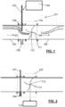
- Figure 1 schematically shows the valve system 101 in a partially open configuration, wherein it allows the fluid to pass at a rate that depends on the aperture of the obstructer 107.
- the pressure decreases to a minimum P min downstream of the valve and the velocity of the fluid increases. Further downstream, the pressure is gradually restored to a linear pressure trend.
- the dashed line represents the pressure trend in the absence of the turbine, while the continuous line represents the same average trend in the presence of the turbine.
- the difference between the minimum pressures reached ( ⁇ P') schematically represents the amount of energy that the turbine can recover without significantly affecting the total energy dissipated during the control action, schematically represented by the pressure drop ( ⁇ P) imposed by the valve to adjust the flow (in this case, the pressure).
- the shaft 112 has one end protruding from the valve body 102.
- the protruding end of the shaft 112 is preferably connected to a user apparatus 114.
- the user apparatus 114 is adapted to use the mechanical power supplied by the shaft 112 due to the rotation of the rotor 111.
- the user apparatus 114 may therefore be an electric generator, or a mechanical apparatus such as, for example, a fan.
- the user apparatus 114 may further comprise known transmission couplings or reducers, not shown for the sake of simplicity.
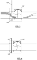
- a deflector 121 may be included upstream of the valve, inserted on the engagement side 120 of the valve obstructer ( Figure 12 ).
- the deflector may be a simple plate anchored and welded to a support, or it may have more aero-fluid-dynamically efficient shapes. The deflector contributes to preventing any dissipations concentrated at the edge 108 of the gate. This will increase the energy production capability when the valve is fully open or almost fully open.
- a valve system according to the present invention may comprise a rotor shaped substantially as a turbine and made in accordance with different manufacturing solutions, which will essentially depend on the type of application of the valve itself.
- the construction of the rotor will primarily depend on the type of fluid for which the valve is to be optimized, whether gas, liquid, steam or any other multi-phase fluid.
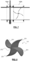
- FIG. 8 illustrates one possible embodiment of the rotor 111, mounted to the shaft 112.
- the rotor 111 comprises four blades 201 which, under the action of the fluid flow passing through the valve 101, are adapted to rotate and produce a torque that will drive the shaft 111.
- the blades of the rotor 111 are curved towards the fluid inlet direction, thus improving the efficiency and facilitating the starting of the rotor. Moreover, preferably, the blades of the rotor 111 are so sized as to occupy as much as possible of the section of the duct.
- FIG 9 shows a further embodiment of a rotor 901 which may be used in a control valve according to the present invention.
- the rotor 901 comprises four blades that, under the action of the fluid flowing through the valve, are adapted to rotate and produce a torque that will drive the shaft 112.
- the rotor 901 comprises a plurality of holes 902, which increase the flow passage surface and the flow coefficient of the fluid.
- the holes 902 are preferably located in the proximity of the axis of rotation of the rotor 902, so that the outermost portions of the blades, i.e. where the lever arm is longest, will still be working, thus producing more power.
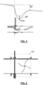
- FIG 10 schematically shows a valve 101b comprising a rotor 111b comprising three blades, which is preferably adapted for use with very viscous liquids.
- FIG 11 schematically shows a valve 101c comprising a rotor 111c comprising ten blades, which is preferably adapted for use with gases.
- the blades may also be flat, e.g. should such choice be dictated by production cost requirements.
- a valve system according to the present invention permits, therefore, recovering at least part of the energy dissipated by the fluid flowing therethrough.
- the energy recovered will depend on the valve opening angle, i.e. the angle of rotation of the obstructer, and on the efficiency of the turbine.
Landscapes
- Engineering & Computer Science (AREA)
- General Engineering & Computer Science (AREA)
- Mechanical Engineering (AREA)
- Chemical & Material Sciences (AREA)
- Combustion & Propulsion (AREA)
- Lift Valve (AREA)
- Pipeline Systems (AREA)
- Flow Control (AREA)
Claims (10)
- Ventilsystem zur Steuerung einer Fluidströmung, wobei das Ventilsystem umfasst:einen Kanaleinen Ventilkörper (102), der dazu geeignet, in eine Unterbrechung des Kanals eingesetzt zu werden, und mit einem Einlass (103) und einem Auslass (104) für einen Fluidstrom in dem Kanal versehen ist,ein Querdurchflussventil (106), das sich in dem Kanal im Wesentlichen quer erstreckt und in dem Ventilkörper (102) stromaufwärts der Fluidströmung platziert ist, wobei das Ventil ein Absperrelement (107) aufweist, das in der Lage ist, sich in dem Kanal quer zu bewegen, um einen Teil der Fluidströmung in dem Kanal "seitlich" zu unterbrechen,Betätigungsmittel (109), die dazu geeignet sind, das Absperrelement aus einer ersten Position, in welcher der Kanal vollständig geöffnet ist, in eine zweite Position zu bewegen, in welcher der Kanal vollständig geschlossen ist,wobei das Ventilsystem ferner umfasst:
einen Rotor, der im Wesentlichen als eine Turbine (111) ausgebildet ist und im Inneren des Ventilkörpers (102) in Bezug auf die Fluidströmung stromabwärts des Absperrelements (107) platziert ist, dadurch gekennzeichnet, dass der Rotor sich in einem Abstand von dem Absperrelement befindet, der innerhalb einer Druckrückgewinnungszone liegt, wobei der Druck durch das Ventil in Abwesenheit der Turbine erzeugt wird, wobei der Abstand in dem Bereich zwischen dem 5- und 6-Fachen des Durchmessers des Kanals liegt. - Ventilsystem nach Anspruch 1, wobei das Querdurchflussventil (106) ein flaches Schieberventil ist, das als Klinge oder als ein Halbmond mit linearem oder gekrümmten Klingenprofil oder als Kugel- oder Halbkugelventil ausgebildet ist.
- Ventilsystem nach Anspruch 1 oder 2, wobei das Absperrelement vom Schieber- und/oder Guillotinen-Typ ist.
- Ventilsystem nach Anspruch 1 oder 2 oder 3, wobei der Rotor (111) mit einer Drehwelle (112) senkrecht zu der Fluidströmung in dem Kanal und zu der Schließrichtung des Absperrelements (107) versehen ist.
- Ventilsystem nach Anspruch 4, wobei die Drehwelle (112) des Rotors (111) aus dem Ventilkörper (102) herausragt und dazu geeignet ist, mit einer Benutzervorrichtung (114) verbunden zu werden, welche die Drehenergie des Rotors nützt.
- Ventilsystem nach Anspruch 1, wobei der Rotor (111) an einem Punkt des minimalen Druckwerts innerhalb der Druckrückgewinnungszone platziert ist.
- Ventilsystem zur Steuerung der Fluidströmung in einem Kanal nach Anspruch 1, wobei der Rotor (111) eine Vielzahl von Schaufeln (201) umfasst, die im Wesentlichen quer zu einer Strömung von vorbeiströmendem Fluid liegen und an der Welle (112) fixiert sind.
- Ventilsystem nach Anspruch 7, wobei die Rotorschaufeln (201) zu der Einlassrichtung der Fluidströmung in das Ventilsystem hin gekrümmt sind.
- Ventilsystem nach einem der vorhergehenden Ansprüche, wobei der Ventilkörper (102) aus einem Stück hergestellt ist, oder alternativ aus zwei getrennten Teilen (102a, 102b) gebildet wird, die miteinander verbunden sind, einem ersten Teil, der das Ventil umfasst, und einem zweiten Teil, der den Rotor umfasst, wobei die Abmessungen des zweiten Teils sich von jenen des ersten Teils unterscheiden können.
- Ventilsystem nach einem der vorhergehenden Ansprüche, ferner umfassend ein Umlenkelement (602), das stromaufwärts des Ventils (106) in einem Bereich positioniert ist, wo das Absperrelement (107) eingerückt wird, wobei das Umlenkelement dazu geeignet ist, fluiddynamisch mit einer Strömung des Fluids zu interagieren.
Applications Claiming Priority (2)
| Application Number | Priority Date | Filing Date | Title |
|---|---|---|---|
| IT102020000015013A IT202000015013A1 (it) | 2020-06-23 | 2020-06-23 | Sistema valvolare a recupero di energia con valvola del tipo a flusso laterale, per la regolazione del flusso di fluido in una condotta |
| PCT/IB2021/055386 WO2021260509A1 (en) | 2020-06-23 | 2021-06-18 | Energy recovery valve system with lateral flow valve for controlling the fluid flow in a duct |
Publications (3)
| Publication Number | Publication Date |
|---|---|
| EP4168697A1 EP4168697A1 (de) | 2023-04-26 |
| EP4168697B1 true EP4168697B1 (de) | 2025-07-02 |
| EP4168697C0 EP4168697C0 (de) | 2025-07-02 |
Family
ID=72473743
Family Applications (1)
| Application Number | Title | Priority Date | Filing Date |
|---|---|---|---|
| EP21742489.4A Active EP4168697B1 (de) | 2020-06-23 | 2021-06-18 | Energierückgewinnungsventilsystem mit seitlichem strömungsventil zur steuerung des fluidstroms in einer leitung |
Country Status (7)
| Country | Link |
|---|---|
| US (1) | US12234798B2 (de) |
| EP (1) | EP4168697B1 (de) |
| CN (1) | CN115735074A (de) |
| CA (1) | CA3188181A1 (de) |
| ES (1) | ES3038865T3 (de) |
| IT (1) | IT202000015013A1 (de) |
| WO (1) | WO2021260509A1 (de) |
Families Citing this family (2)
| Publication number | Priority date | Publication date | Assignee | Title |
|---|---|---|---|---|
| US12510166B1 (en) * | 2024-10-04 | 2025-12-30 | Hui-Chuan Liao | Blast gate capable of preventing gate-dropping |
| US12297546B1 (en) * | 2024-10-10 | 2025-05-13 | Isaiah Ruehle-May | Turbine-induced ICCP system for metallic pipelines |
Family Cites Families (9)
| Publication number | Priority date | Publication date | Assignee | Title |
|---|---|---|---|---|
| FR1417308A (fr) * | 1964-09-30 | 1965-11-12 | Rochar Electronique | Interrupteurs hydrauliques pour capteurs débitmétriques |
| US3918856A (en) * | 1974-02-19 | 1975-11-11 | Trw Inc | Gerotor fluid controller with twistable blade energy storing means |
| US20090165866A1 (en) * | 2007-12-28 | 2009-07-02 | Giovanni Fima | Valve With Built-In Sensor |
| EP2085753B1 (de) * | 2008-01-31 | 2011-11-16 | Services Pétroliers Schlumberger | Durchflussmessgerät eingesetzt in einem Kugelventil |
| ITMI20120234A1 (it) * | 2012-02-16 | 2013-08-17 | Milano Politecnico | Valvola di regolazione a recupero di energia |
| KR101245450B1 (ko) * | 2012-05-14 | 2013-03-19 | 박종흠 | 급배수관용 발전형 감압장치 |
| US9046191B2 (en) * | 2012-08-30 | 2015-06-02 | Fisher Controls International, Llc | Valve body with upper flow diverter |
| ITMO20130051A1 (it) * | 2013-02-27 | 2014-08-28 | Lorenzo Ferioli | "valvola di regolazione con recupero energetico" |
| KR102088879B1 (ko) * | 2019-08-12 | 2020-03-13 | 동해에코에너지(주) | 자가발전형 스마트 밸브의 원격제어 시스템 |
-
2020
- 2020-06-23 IT IT102020000015013A patent/IT202000015013A1/it unknown
-
2021
- 2021-06-18 US US18/002,772 patent/US12234798B2/en active Active
- 2021-06-18 CA CA3188181A patent/CA3188181A1/en active Pending
- 2021-06-18 ES ES21742489T patent/ES3038865T3/es active Active
- 2021-06-18 WO PCT/IB2021/055386 patent/WO2021260509A1/en not_active Ceased
- 2021-06-18 CN CN202180045016.2A patent/CN115735074A/zh active Pending
- 2021-06-18 EP EP21742489.4A patent/EP4168697B1/de active Active
Also Published As
| Publication number | Publication date |
|---|---|
| US20230287859A1 (en) | 2023-09-14 |
| EP4168697A1 (de) | 2023-04-26 |
| ES3038865T3 (en) | 2025-10-15 |
| IT202000015013A1 (it) | 2021-12-23 |
| WO2021260509A1 (en) | 2021-12-30 |
| EP4168697C0 (de) | 2025-07-02 |
| CA3188181A1 (en) | 2021-12-30 |
| CN115735074A (zh) | 2023-03-03 |
| US12234798B2 (en) | 2025-02-25 |
Similar Documents
| Publication | Publication Date | Title |
|---|---|---|
| JP4909405B2 (ja) | 遠心圧縮機 | |
| EP4168697B1 (de) | Energierückgewinnungsventilsystem mit seitlichem strömungsventil zur steuerung des fluidstroms in einer leitung | |
| EP1461551B1 (de) | Drehklappenventil | |
| US8128356B2 (en) | Mixed flow turbine | |
| US9599252B2 (en) | Energy recovering flow control valve | |
| EP2360401B1 (de) | Tellerventil mit linearer Bereichszunahme | |
| CN101899998B (zh) | 涡轮增压器 | |
| EP3929430A1 (de) | Läufer für eine hydraulische turbine | |
| CN101776165B (zh) | 一种叶轮式壳体的防水锤静音止回阀 | |
| US12398810B2 (en) | Energy recovery valve system with spherical segment valve for controlling the fluid flow in a duct | |
| JP7648053B2 (ja) | クロスフロータービン | |
| CN113236818A (zh) | 一种低能耗高频响的控制阀及控制方法 | |
| GB2392956A (en) | Controlling inlet to turbocharger turbine | |
| JP2007192128A (ja) | 可変容量ターボチャージャ | |
| GB2530094A (en) | Valve assembly | |
| JP7548892B2 (ja) | 弁装置 | |
| RU59762U1 (ru) | Регулятор давления | |
| JP2006313011A (ja) | 流量調節弁および流量調節弁用のブシュ | |
| JPS61250303A (ja) | 軸流タ−ボ機械の可変ノズル装置 | |
| JPH04347376A (ja) | クロスフロー水車 |
Legal Events
| Date | Code | Title | Description |
|---|---|---|---|
| STAA | Information on the status of an ep patent application or granted ep patent |
Free format text: STATUS: UNKNOWN |
|
| STAA | Information on the status of an ep patent application or granted ep patent |
Free format text: STATUS: THE INTERNATIONAL PUBLICATION HAS BEEN MADE |
|
| PUAI | Public reference made under article 153(3) epc to a published international application that has entered the european phase |
Free format text: ORIGINAL CODE: 0009012 |
|
| STAA | Information on the status of an ep patent application or granted ep patent |
Free format text: STATUS: REQUEST FOR EXAMINATION WAS MADE |
|
| 17P | Request for examination filed |
Effective date: 20221206 |
|
| AK | Designated contracting states |
Kind code of ref document: A1 Designated state(s): AL AT BE BG CH CY CZ DE DK EE ES FI FR GB GR HR HU IE IS IT LI LT LU LV MC MK MT NL NO PL PT RO RS SE SI SK SM TR |
|
| P01 | Opt-out of the competence of the unified patent court (upc) registered |
Effective date: 20230615 |
|
| DAV | Request for validation of the european patent (deleted) | ||
| DAX | Request for extension of the european patent (deleted) | ||
| GRAP | Despatch of communication of intention to grant a patent |
Free format text: ORIGINAL CODE: EPIDOSNIGR1 |
|
| STAA | Information on the status of an ep patent application or granted ep patent |
Free format text: STATUS: GRANT OF PATENT IS INTENDED |
|
| INTG | Intention to grant announced |
Effective date: 20250312 |
|
| GRAS | Grant fee paid |
Free format text: ORIGINAL CODE: EPIDOSNIGR3 |
|
| GRAA | (expected) grant |
Free format text: ORIGINAL CODE: 0009210 |
|
| STAA | Information on the status of an ep patent application or granted ep patent |
Free format text: STATUS: THE PATENT HAS BEEN GRANTED |
|
| AK | Designated contracting states |
Kind code of ref document: B1 Designated state(s): AL AT BE BG CH CY CZ DE DK EE ES FI FR GB GR HR HU IE IS IT LI LT LU LV MC MK MT NL NO PL PT RO RS SE SI SK SM TR |
|
| REG | Reference to a national code |
Ref country code: GB Ref legal event code: FG4D |
|
| REG | Reference to a national code |
Ref country code: CH Ref legal event code: EP |
|
| REG | Reference to a national code |
Ref country code: DE Ref legal event code: R096 Ref document number: 602021033392 Country of ref document: DE |
|
| REG | Reference to a national code |
Ref country code: IE Ref legal event code: FG4D |
|
| U01 | Request for unitary effect filed |
Effective date: 20250728 |
|
| U07 | Unitary effect registered |
Designated state(s): AT BE BG DE DK EE FI FR IT LT LU LV MT NL PT RO SE SI Effective date: 20250801 |
|
| P04 | Withdrawal of opt-out of the competence of the unified patent court (upc) registered |
Free format text: CASE NUMBER: APP_503149_1/2023 Effective date: 20250801 |
|
| REG | Reference to a national code |
Ref country code: ES Ref legal event code: FG2A Ref document number: 3038865 Country of ref document: ES Kind code of ref document: T3 Effective date: 20251015 |
|
| PG25 | Lapsed in a contracting state [announced via postgrant information from national office to epo] |
Ref country code: IS Free format text: LAPSE BECAUSE OF FAILURE TO SUBMIT A TRANSLATION OF THE DESCRIPTION OR TO PAY THE FEE WITHIN THE PRESCRIBED TIME-LIMIT Effective date: 20251102 |
|
| PG25 | Lapsed in a contracting state [announced via postgrant information from national office to epo] |
Ref country code: NO Free format text: LAPSE BECAUSE OF FAILURE TO SUBMIT A TRANSLATION OF THE DESCRIPTION OR TO PAY THE FEE WITHIN THE PRESCRIBED TIME-LIMIT Effective date: 20251002 |
|
| PG25 | Lapsed in a contracting state [announced via postgrant information from national office to epo] |
Ref country code: HR Free format text: LAPSE BECAUSE OF FAILURE TO SUBMIT A TRANSLATION OF THE DESCRIPTION OR TO PAY THE FEE WITHIN THE PRESCRIBED TIME-LIMIT Effective date: 20250702 |