EP4168239B1 - Verfahren zum fluidumformen und füllen von behältern - Google Patents
Verfahren zum fluidumformen und füllen von behältern Download PDFInfo
- Publication number
- EP4168239B1 EP4168239B1 EP20743790.6A EP20743790A EP4168239B1 EP 4168239 B1 EP4168239 B1 EP 4168239B1 EP 20743790 A EP20743790 A EP 20743790A EP 4168239 B1 EP4168239 B1 EP 4168239B1
- Authority
- EP
- European Patent Office
- Prior art keywords
- container
- product
- volume
- exterior surface
- preform
- Prior art date
- Legal status (The legal status is an assumption and is not a legal conclusion. Google has not performed a legal analysis and makes no representation as to the accuracy of the status listed.)
- Active
Links
Images


Classifications
-
- B—PERFORMING OPERATIONS; TRANSPORTING
- B29—WORKING OF PLASTICS; WORKING OF SUBSTANCES IN A PLASTIC STATE IN GENERAL
- B29C—SHAPING OR JOINING OF PLASTICS; SHAPING OF MATERIAL IN A PLASTIC STATE, NOT OTHERWISE PROVIDED FOR; AFTER-TREATMENT OF THE SHAPED PRODUCTS, e.g. REPAIRING
- B29C49/00—Blow-moulding, i.e. blowing a preform or parison to a desired shape within a mould; Apparatus therefor
- B29C49/42—Component parts, details or accessories; Auxiliary operations
- B29C49/46—Component parts, details or accessories; Auxiliary operations characterised by using particular environment or blow fluids other than air
-
- B—PERFORMING OPERATIONS; TRANSPORTING
- B29—WORKING OF PLASTICS; WORKING OF SUBSTANCES IN A PLASTIC STATE IN GENERAL
- B29C—SHAPING OR JOINING OF PLASTICS; SHAPING OF MATERIAL IN A PLASTIC STATE, NOT OTHERWISE PROVIDED FOR; AFTER-TREATMENT OF THE SHAPED PRODUCTS, e.g. REPAIRING
- B29C49/00—Blow-moulding, i.e. blowing a preform or parison to a desired shape within a mould; Apparatus therefor
- B29C49/42—Component parts, details or accessories; Auxiliary operations
- B29C49/4273—Auxiliary operations after the blow-moulding operation not otherwise provided for
- B29C49/42808—Filling the article
-
- B—PERFORMING OPERATIONS; TRANSPORTING
- B29—WORKING OF PLASTICS; WORKING OF SUBSTANCES IN A PLASTIC STATE IN GENERAL
- B29C—SHAPING OR JOINING OF PLASTICS; SHAPING OF MATERIAL IN A PLASTIC STATE, NOT OTHERWISE PROVIDED FOR; AFTER-TREATMENT OF THE SHAPED PRODUCTS, e.g. REPAIRING
- B29C49/00—Blow-moulding, i.e. blowing a preform or parison to a desired shape within a mould; Apparatus therefor
- B29C49/42—Component parts, details or accessories; Auxiliary operations
- B29C49/46—Component parts, details or accessories; Auxiliary operations characterised by using particular environment or blow fluids other than air
- B29C2049/4602—Blowing fluids
- B29C2049/465—Blowing fluids being incompressible
- B29C2049/4664—Blowing fluids being incompressible staying in the final article
-
- B—PERFORMING OPERATIONS; TRANSPORTING
- B29—WORKING OF PLASTICS; WORKING OF SUBSTANCES IN A PLASTIC STATE IN GENERAL
- B29C—SHAPING OR JOINING OF PLASTICS; SHAPING OF MATERIAL IN A PLASTIC STATE, NOT OTHERWISE PROVIDED FOR; AFTER-TREATMENT OF THE SHAPED PRODUCTS, e.g. REPAIRING
- B29C2949/00—Indexing scheme relating to blow-moulding
- B29C2949/07—Preforms or parisons characterised by their configuration
- B29C2949/0715—Preforms or parisons characterised by their configuration the preform having one end closed
-
- B—PERFORMING OPERATIONS; TRANSPORTING
- B29—WORKING OF PLASTICS; WORKING OF SUBSTANCES IN A PLASTIC STATE IN GENERAL
- B29C—SHAPING OR JOINING OF PLASTICS; SHAPING OF MATERIAL IN A PLASTIC STATE, NOT OTHERWISE PROVIDED FOR; AFTER-TREATMENT OF THE SHAPED PRODUCTS, e.g. REPAIRING
- B29C49/00—Blow-moulding, i.e. blowing a preform or parison to a desired shape within a mould; Apparatus therefor
- B29C49/02—Combined blow-moulding and manufacture of the preform or the parison
- B29C49/06—Injection blow-moulding
-
- B—PERFORMING OPERATIONS; TRANSPORTING
- B29—WORKING OF PLASTICS; WORKING OF SUBSTANCES IN A PLASTIC STATE IN GENERAL
- B29C—SHAPING OR JOINING OF PLASTICS; SHAPING OF MATERIAL IN A PLASTIC STATE, NOT OTHERWISE PROVIDED FOR; AFTER-TREATMENT OF THE SHAPED PRODUCTS, e.g. REPAIRING
- B29C49/00—Blow-moulding, i.e. blowing a preform or parison to a desired shape within a mould; Apparatus therefor
- B29C49/42—Component parts, details or accessories; Auxiliary operations
- B29C49/4273—Auxiliary operations after the blow-moulding operation not otherwise provided for
- B29C49/4283—Deforming the finished article
- B29C49/42832—Moving or inverting sections, e.g. inverting bottom as vacuum panel
-
- B—PERFORMING OPERATIONS; TRANSPORTING
- B29—WORKING OF PLASTICS; WORKING OF SUBSTANCES IN A PLASTIC STATE IN GENERAL
- B29K—INDEXING SCHEME ASSOCIATED WITH SUBCLASSES B29B, B29C OR B29D, RELATING TO MOULDING MATERIALS OR TO MATERIALS FOR MOULDS, REINFORCEMENTS, FILLERS OR PREFORMED PARTS, e.g. INSERTS
- B29K2067/00—Use of polyesters or derivatives thereof, as moulding material
- B29K2067/003—PET, i.e. poylethylene terephthalate
-
- B—PERFORMING OPERATIONS; TRANSPORTING
- B29—WORKING OF PLASTICS; WORKING OF SUBSTANCES IN A PLASTIC STATE IN GENERAL
- B29L—INDEXING SCHEME ASSOCIATED WITH SUBCLASS B29C, RELATING TO PARTICULAR ARTICLES
- B29L2031/00—Other particular articles
- B29L2031/712—Containers; Packaging elements or accessories, Packages
- B29L2031/7158—Bottles
Definitions
- the present technology relates to simultaneously forming and filling a container, including controlling a final product level in the container.
- plastic containers such as containers formed from one or more polymers.
- Common polymers used to form containers include polyesters, such as polyethylene terephthalate (PET), high and low density polyethylenes, polycarbonate, and polypropylene, among others.
- PET polyethylene terephthalate
- Plastic containers can be made using various blow molding processes including injection blow molding and extrusion blow molding.
- Injection blow molding can be used to form certain plastic containers in one or more stages and can involve use of a stretch rod.
- the plastic is first molded into a preform using an injection molding process.
- the preform includes the neck and finish of the container to be formed, which can include threading thereon, and a closed distal end.
- the preform can then be heated above the plastic glass transition temperature, longitudinally stretched with a stretch rod, and blown using high-pressure gas (e.g., air) into a container conforming to a mold.
- high-pressure gas e.g., air
- the injection stretch blow molding process can be used to form plastic containers for packaging consumer beverages, as well as other liquids and materials.
- the process has some inherent limitations, which include undesirable gate wells or discontinuities on the bottom portions of containers as well as limitations on the possible spectrum of designs that can be realized using the stretch blow molding process, such as containers incorporating a handle or void space therein.
- Extrusion blow molding can be used to form certain plastic containers where a continuously extruded hot plastic tube or parison is captured within a mold and inflated against the inner surfaces of the mold to form a container blank.
- the mold can be designed to travel at the speed at which the extruded parison is moving when it closes on the parison so that the process can operate on a continuous basis.
- extrusion blow molding machines including shuttle molds that are designed to travel in a linear motion and extrusion blow molding wheels that travel in a rotary or circular motion.
- blow molding containers and subsequent filling of containers have consequently developed as two independent processes, in many cases operated at different facilities.
- some filling facilities have installed blow molding equipment on site, in many cases integrating blow molders directly into filling lines.
- Equipment manufacturers have recognized this advantage and are selling "integrated" systems that are designed to insure that the blow molder and the filler are fully synchronized.
- blow molding and filling continue to be two independent, distinct processes. As a result, significant costs may be incurred in separately performing these two processes.
- simultaneous forming and filling operations using a product, where the product remains in the resultant container can present issues in accurately obtaining a desired product level in the resultant container.
- the desired product level can often be less than the maximum volume of the container, where an air or gas space is maintained above a defined product or liquid level for various reasons.
- Example reasons include where the air space permits expansion/contraction in response to temperature changes without exerting substantial pressure changes on the container itself, where the air space provides a uniform aesthetic to the filled, finished and capped container, where the accurate fill level is used to identify a definite amount of product within the container, where the air space facilitates mixing of the container contents by inversion or shaking of the container when sealed, where the air space permits addition of additional material, whether solid or liquid, to the product within the container, and so on.
- US 2019/240891 A1 is considered to represent the closest prior art, and its disclosure forms the basis of the preamble of claim 1. Further background information can be obtained from US 2019/232545 A1 , and US 2017/021553 A1 .
- the present technology includes systems, processes, and articles of manufacture that relate to control and adjustment of a product level in a container, including where the container formed and filled from a preform using the product, the product remaining in the container as an end product.
- compositions or processes specifically envisions embodiments consisting of, and consisting essentially of, A, B and C, excluding an element D that can be recited in the art, even though element D is not explicitly described as being excluded herein.
- ranges are, unless specified otherwise, inclusive of endpoints and include all distinct values and further divided ranges within the entire range. Thus, for example, a range of "from A to B" or “from about A to about B” is inclusive of A and of B. Disclosure of values and ranges of values for specific parameters (such as amounts, weight percentages, etc.) are not exclusive of other values and ranges of values useful herein. It is envisioned that two or more specific exemplified values for a given parameter can define endpoints for a range of values that can be claimed for the parameter.
- Parameter X is exemplified herein to have value A and also exemplified to have value Z, it is envisioned that Parameter X can have a range of values from about A to about Z.
- disclosure of two or more ranges of values for a parameter (whether such ranges are nested, overlapping or distinct) subsume all possible combination of ranges for the value that might be claimed using endpoints of the disclosed ranges.
- Parameter X is exemplified herein to have values in the range of 1-10, or 2-9, or 3-8, it is also envisioned that Parameter X can have other ranges of values including 1-9, 1-8, 1-3, 1-2, 2-10, 2-8, 2-3, 3-10, 3-9, and so on.
- first, second, third, etc. can be used herein to describe various elements, components, regions, layers and/or sections, these elements, components, regions, layers and/or sections should not be limited by these terms. These terms can be only used to distinguish one element, component, region, layer or section from another region, layer or section. Terms such as “first,” “second,” and other numerical terms when used herein do not imply a sequence or order unless clearly indicated by the context. Thus, a first element, component, region, layer or section discussed below could be termed a second element, component, region, layer or section without departing from the teachings of the example embodiments.
- spatially relative terms such as “inner,” “outer,” “beneath,” “below,” “lower,” “above,” “upper,” and the like, can be used herein for ease of description to describe one element or feature's relationship to another element(s) or feature(s) as illustrated in the figures.
- Spatially relative terms can be intended to encompass different orientations of the device in use or operation in addition to the orientation depicted in the figures. For example, if the device in the figures is turned over, elements described as “below” or “beneath” other elements or features would then be oriented “above” the other elements or features.
- the example term “below” can encompass both an orientation of above and below.
- the device can be otherwise oriented (rotated 90 degrees or at other orientations) and the spatially relative descriptors used herein interpreted accordingly.
- the present technology allows for controlling a level of a product in a container, where the container can be formed and filled using the product.
- Product level can be controlled by engaging an exterior surface of the container containing the product, where the product is at a first product level. Applying a force to the exterior surface of the container can then cause the container to change from a first volume to a second volume. Cessation of the force can result in the container containing the product at a second product level.
- the first product level can relate to an amount of product substantially equal to the first volume. It is also possible to have the second product level relate to an amount of product substantially equal to the second volume.
- Certain embodiments include where the container remains at the second volume following cessation of the force. For example, after engaging the exterior surface of the container, a force can be applied by pulling on the exterior surface of the container. Pulling on the exterior surface can increase the volume of the container and can cause the level of the product in the container to drop from the first product level to the second product level.
- Various filling operations and various forming and filling operations that employ the product to form and fill the container can result in the container being substantially full of product. Engaging and applying the force to the exterior surface of such a filled container can result in the second volume being greater than the first volume and the first product level dropping to the second product level.
- Cessation of the force pushing on the exterior surface of the container can result in the container substantially remaining at the second volume, being greater than the first volume in this case, thereby causing the product in the container to drop a defined amount to the second product level in the container.
- the container wall can have formed therein a shape or recess that can be inverted or where at least a portion pops out and remains in such position following cessation of the force.
- Containers used in the present technology can be formed in various ways and certain methods include using the product to simultaneously form and fill the container by expanding a preform within a mold.
- the process can include dispensing the product into a preform to form and fill a container with the product.
- At least a portion of the preform can be positioned within a mold cavity that defines an internal surface and a blow nozzle can be used to transfer the product to the preform to urge the preform to expand toward the internal surface of the mold cavity and form the container.
- the product can remain within the container as an end product and the resultant container can be filled substantially to capacity with the product.
- Examples of using a stretch rod, an exterior rod, and a stretch rod in conjunction with an exterior rod in operating on a preform to form a container include those described in U.S. Patent Nos. 8,727,758 to Eberle et al. and 9,802,375 to Lisch et al. and those described in Int'l Pub. No. WO/2012/037057A2 to Maki et al. .
- Embodiments of the invention include employing the following aspects in engaging the exterior surface of the container containing the product at the first product level.
- Engaging the exterior surface of the container can include engaging an engagement feature on the exterior surface of the container.
- the engagement feature can be an injection molded feature of a preform used to form the container.
- the engagement feature include a projection on the exterior surface of the container.
- Various embodiments can have the projection result from a sprue in forming the container; e.g., a sprue resulting from injection molding the preform used to subsequently blow mold the container.
- the projection can also result from extrusion blow molding of the container; e.g., a portion of the extruded parison that is pinched or captured by a lower portion of a mold used to blow molding.
- the engagement feature is a projection
- the projection can be located within a recessed portion of the exterior surface of the container.
- This recessed portion can exist prior to applying the force to the exterior surface of the container to cause the container to change from the first volume to the second volume. Pulling on the projection within the recessed portion, for example, can cause all or part of the recessed portion to expand and even invert or pop out from a remainder of the container.
- the recessed portion of the exterior surface of the container can change to a projecting portion of the exterior surface of the container following application of the force to the exterior surface of the container to cause the container to change from the first volume to the second volume.
- Certain embodiments include various post product level control steps.
- the container containing the product at the second product level can be sealed, for example, to preserve the accurate fill level and ensure uniformity of filled containers.
- One or more labels can be applied to the container.
- Containers can be packaged and palletized in certain ways or the container filled with product can be dispensed on-demand.
- the present technology also includes various systems and system components having the features provided herein. Methods of using such systems and components for simultaneously forming and filling a container with a product are also contemplated by the present technology. Various articles of manufacture are provided by the present technology, including various products-by-process.
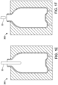
- Figures 1A-1F illustrate a series of schematic side views depicting an exterior rod 100 guiding a preform 112 during a container forming process.
- a stretch rod 22 and exterior rod 100 can be actuated concurrently and independently to effect a predetermined stretch and/or forming process.
- exterior rod 100 can be actuated from the base of a mold cavity 302 and can be initially activated to physically touch or contact a preform 112 prior to blowing, or the exterior rod 100 can stop prior to contacting the preform 112; e.g., Figures 1A-1B .
- the exterior rod 100 can function up to about 20 mm from the preform 112; however, in some embodiments the exterior rod 100 can improve quality and can insure that a portion of the preform 112 engages the exterior rod 100 so that the preform is maintained in a desired position within mold cavity 302.
- a telescoping version of exterior rod 100 can be used. That is, in some embodiments, a telescoping exterior rod 100 can be employed having a first section 104 slidably received within a second section 108. It should be recognized, however, that additional telescoping sections can be used.
- the exterior rod 100 can engage preform 112 at any time prior to or immediately following initiation of the container inflation; however, if exterior rod 100 is intended to engage preform 112 prior to inflation, the preform 112 can be loaded and then the exterior rod 100 can be engaged or actuated. The stretch rod 22 can be actuated next, and can engage preform 112 along with the exterior rod 100. Once the preform 112 is engaged with the exterior rod 100, inflation of the preform 112 to the resultant container can begin.
- the preform 112 can be inflated with the use of high pressure air or liquid, or a first step of low pressure air or liquid that is followed by a second step of high pressure air or liquid.
- Preform 112 can begin to inflate away from the stretch rod 22, and the stretch rod 22 can remain in place, or retract from the inflating preform 22 as the container is formed.
- the stretch rod 22 can be set to the desired depth in the container such that once the seal pin is closed, a product fill level can be at or close to a desired height within the container.
- the exterior rod 100 can then be removed from the container, the nozzle raised, and the container removed from the mold, fully formed and filled, with the product remaining inside the container.
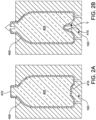
- FIG. 2A-2C illustrated therein is a series of schematic side views, not embodying the invention, depicting an exterior rod adjusting a final product level in a filled container formed according to the container forming process shown in Figures 1A-1F .
- Shown in Figure 2A is a container 200 that is filled with product 205 to substantially a capacity of the container 200.
- a fill level of the product 205 at substantially the capacity of the container 200, can account for a first product level 210 in this example.
- an exterior surface 215 of the container 200 containing the product 205 at the first product level 210 can have a force applied thereto to cause the container 200 to change from a first volume to a second volume.
- the particular example shown uses the exterior rod 100 to engage and apply the force to the exterior surface 215 of the container 200.
- Application of the force by pushing on the exterior surface 215 of the container 200 using the exterior rod 100 causes a deflection of the container 200 and a reduction in the volume of the container proportional to the deflected volume denoted by V in Figure 2B .
- a corresponding amount of the product 205 to the deflected volume V exits the top of the container 200 as the product moves past the first product level 210 (limited by the capacity of the container 200), as indicated by the arrow located at the top of the container 200 in Figure 2B .
- the product 205 exiting the container 200 as a result of the deflecting force applied by the exterior rod 100 can be directed away from the container 200 in some fashion and can even be captured and reused.
- cessation of the force results in the container 200 containing the product 205 at a second product level 220.
- the exterior rod 100 is retracted and no longer applying the force to the exterior surface 215 of the container 200 and the deflection (and deflected volume V) caused thereby is absent, where the container 200 has returned to substantially the same starting shape as shown in Figure 2A .
- the first product level 210 has accordingly dropped to the second product level 220 in proportion to the deflected volume V in reference to the exited volume denoted by V in Figure 2C .
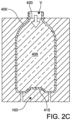
- Figure 3 illustrates a container 400 formed and filled with product 405 according to the container forming process shown in Figures 1A-1F , where an exterior rod 100 can engage an exterior surface 415 of the filled container 400.
- the container 400 is shown within the mold 300; however, the container 400 can be entirely removed from the mold 300 or a bottom portion 425 of the mold 300 can be removed from a remainder of the mold 300.
- the container 400 can be filled with product 405 to substantially the capacity of the container 400, which can account for the first product level 410 in this particular embodiment.
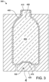
- Figure 4 illustrates a detailed view of the circled inset marked - 4 - in Figure 3 , where the exterior rod 100 is shown engaged with an exterior feature 430 on the exterior surface 415 of the container 400.
- the exterior feature 430 can be configured to be complementary to an end portion 435 of the exterior rod 100.
- the end portion 435 of the exterior rod 100 can engage the exterior feature 430 and allow a force to be applied thereto, where the force can also be applied to the exterior surface 415 or transmitted to the exterior surface 415 through the exterior feature 430.
- the complementarity and engagement of the end portion 435 with the exterior feature 430 can allow various directions of force to be applied to the exterior surface 415 of the container 400.
- the exterior rod 100 can push on the exterior surface 415 as shown in Figure 2B .
- the engagement of the end portion 435 with the exterior feature 430 also allows the exterior rod 100 to pull on the exterior feature 430, which transmits the pulling force to the exterior surface 415 of the container 400.
- the exterior feature 430 can include a resilient collar 440 that deforms when passing through an aperture 445 in the end portion 435 of the exterior rod 100.
- the resilient collar 440 springs back to a diameter larger than a diameter of the aperture 445 upon entering a recess 450 in the end portion 435.
- the exterior feature 430 can snap into the end portion 435 of the exterior rod in this fashion. It is understood that other configurations, including various articulating means and complementary engagement means, can be used to couple the exterior feature 430 and the exterior rod 100.
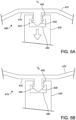
- Figures 5A-5B illustrate the detailed view of Figure 4 , where at least the bottom portion 425 of the mold 300 is separated from the container 400.
- the series of views depict how the exterior rod 100 can be used to apply a pulling force on the exterior feature 430 of the container 400 to change a first volume V 1 ( Figure 5A ) to a second volume V 2 ( Figure 5B ), thereby adjusting the first product level 410 to a second (final) product level 460 (see Figure 3 ) in the filled container 400.
- the exterior rod 100 engaged with the exterior feature 430, applies a pulling force to the exterior surface 415 of the container 400 that results in the container 400 increasing in volume; i.e., V 2 > V 1 .
- the particular embodiment depicted has the exterior feature 430 located within a recess 465 formed in the wall 470 of the container 400.
- the recess 465 is located on the bottom of the container 400.
- This recess 465 can be inverted when the exterior rod 100 applies the pulling force to the exterior feature 430, where a portion of the wall 470 of the container 400 pops out and remains in such position following cessation of the force.
- the container changes from the first volume V 1 ( Figure 5A ) to the second volume V 2 ( Figure 5B ) and the product 405 in the container changes from the first product level 410 to the second product level 460.
- the portion of the wall 470 partially return to its former recess 465 shape or where the wall 470 forms a substantially planar surface with a remainder of the bottom of the container 400 instead of protruding therefrom. It is also possible to have multiple concentric stepped recesses 465 that can be pulled and inverted in successive stages providing multiple defined second product level 460 options.
- the presently described methods and systems can simultaneously form and fill a container and reproducibly and accurately control a final product level in the container.
- the present technology can be used in conjunction with other container manufacturing methods, such as for example, extrusion blow molding, one step injection stretch blow molding, and injection blow molding, and can be used with various container materials including, for example, thermoplastic, high density polyethylene, polypropylene, polyethylene naphthalate (PEN), a PET/PEN blend or copolymer, and various multilayer structures may be suitable for the manufacture of plastic containers and used in connection with the principles described herein.
- PEN polyethylene naphthalate
- PET/PEN blend or copolymer a PET/PEN blend or copolymer
- multilayer structures may be suitable for the manufacture of plastic containers and used in connection with the principles described herein.
- the present disclosure contemplates the production of PET containers, it is understood that other polyolefin materials (e.g., polyethylene, polypropylene, polyester, etc.) as well as a number of other plastics
Landscapes
- Engineering & Computer Science (AREA)
- Manufacturing & Machinery (AREA)
- Mechanical Engineering (AREA)
- Containers Having Bodies Formed In One Piece (AREA)
- Blow-Moulding Or Thermoforming Of Plastics Or The Like (AREA)
Claims (12)
- Verfahren zum Steuern eines Füllstands eines Produkts (405) in einem Behälter (400), wobei das Verfahren umfasst:Eingreifen in eine Außenfläche (415) des Behälters (400), der das Produkt auf einem ersten Produktfüllstand (410) enthält;Aufbringen einer Kraft auf die Außenfläche (415) des Behälters (400), um zu bewirken, dass sich der Behälter von einem ersten Volumen (V1) zu einem zweiten Volumen (V2) ändert;woraufhin die Aufhebung der Kraft dazu führt, dass der Behälter (400) das Produkt (405) auf einem zweiten Produktfüllstand (460) enthält,dadurch gekennzeichnet, dass:das erste Volumen (V1) kleiner als das zweite Volumen (V2) ist;das Eingreifen in die Außenfläche (415) des Behälters (400), der das Produkt auf dem ersten Produktfüllstand (410) enthält, das Eingreifen in ein Eingriffsmerkmal (430) auf der Außenfläche (415) des Behälters (400) beinhaltet, wobei das Eingriffsmerkmal (430) ein Vorsprung auf der Außenfläche (415) des Behälters (400) ist, wobei der Vorsprung ein Anguss ist, der aus einem Spritzgießen eines Vorformlings (112) resultiert, der zum Bilden des Behälters (400) verwendet wird, undAufbringen der Kraft auf die Außenfläche (415) des Behälters (400), um zu bewirken, dass sich der Behälter (400) vom ersten Volumen (V1) zum zweiten Volumen (V2) ändert, ein Ziehen des Vorsprungs mit einem komplementären Endabschnitt (435) einer äußeren Stange (100) beinhaltet, die außerhalb des Behälters (400) angeordnet ist, um zu bewirken, dass das erste Volumen (V1) auf das zweite Volumen (V2) vergrößert wird.
- Verfahren nach Anspruch 1, wobei sich der erste Produktfüllstand (410) auf eine Produktmenge bezieht, die im Wesentlichen gleich dem ersten Volumen (V1) ist.
- Verfahren nach Anspruch 1, wobei sich der zweite Produktfüllstand (460) auf eine Produktmenge bezieht, die im Wesentlichen gleich dem zweiten Volumen ist.
- Verfahren nach Anspruch 1, wobei der Behälter (400) nach Aufheben der Kraft auf dem zweiten Volumen (V2) verbleibt.
- Verfahren nach Anspruch 1, wobei vor dem Aufbringen einer Kraft auf die Außenfläche (415) des Behälters (400) zum Bewirken, dass sich der Behälter von einem ersten Volumen (V1) zu einem zweiten Volumen (V2) ändert, das Verfahren ferner das Abgeben des Produkts (405) in den Vorformling (112) umfasst, um den Behälter mit dem Produkt (405) zu bilden und zu füllen.
- Verfahren nach Anspruch 5, wobei zumindest ein Teil des Vorformlings (112) in einem Formhohlraum (302) positioniert wird, der eine Innenfläche definiert, und eine Blasdüse das Produkt (405) auf den Vorformling (112) überträgt, um den Vorformling (112) zu zwingen, sich zur Innenfläche des Formhohlraums (302) hin auszudehnen und den Behälter (400) zu bilden, wobei das Produkt (405) in dem Behälter (400) verbleibt.
- Verfahren nach Anspruch 6, wobei, bevor die Blasdüse das Produkt (405) auf den Vorformling (112) überträgt, um den Vorformling zu zwingen, sich zur Innenfläche des Formhohlraums (302) hin auszudehnen und den Behälter (400) zu bilden, der Vorformling (112) innerhalb des Formhohlraums (302) unter Verwendung einer Streckstange (22) mechanisch gestreckt wird.
- Verfahren nach Anspruch 7, wobei der Endabschnitt (435) der äußeren Stange (100) an einer Außenfläche des Vorformlings anliegt, wenn der Vorformling innerhalb des Formhohlraums (302) unter Verwendung der Streckstange (22) mechanisch gestreckt wird.
- Verfahren nach Anspruch 1, wobei sich der Vorsprung innerhalb eines vertieften Abschnitts der Außenfläche (415) des Behälters (400) befindet, der vor dem Aufbringen der Kraft auf die Außenfläche (415) des Behälters (400) vorhanden ist, um zu bewirken, dass sich der Behälter vom ersten Volumen (V1) zum zweiten Volumen (V2) ändert.
- Verfahren nach Anspruch 9, wobei sich der vertiefte Abschnitt der Außenfläche (415) des Behälters (400) in einen vorstehenden Abschnitt der Außenfläche (415) des Behälters (400) oder einen ebenen Abschnitt der Außenfläche (415) des Behälters (400) ändert, nachdem die Kraft auf die Außenfläche (415) des Behälters (400) aufgebracht wurde, um zu bewirken, dass sich der Behälter (400) vom ersten Volumen (V1) zum zweiten Volumen (V2) ändert.
- Verfahren nach Anspruch 1, ferner umfassend das Entfernen des Vorsprungs von der Außenfläche (415) des Behälters (400) nach dem Aufheben der Kraft.
- Verfahren nach Anspruch 1, ferner umfassend das Versiegeln des Behälters (400), der das Produkt (405) enthält, auf dem zweitem Produktfüllstand (460).
Applications Claiming Priority (1)
| Application Number | Priority Date | Filing Date | Title |
|---|---|---|---|
| PCT/IB2020/055796 WO2021255504A1 (en) | 2020-06-19 | 2020-06-19 | Method of fluid forming and filling containers |
Publications (2)
| Publication Number | Publication Date |
|---|---|
| EP4168239A1 EP4168239A1 (de) | 2023-04-26 |
| EP4168239B1 true EP4168239B1 (de) | 2024-08-07 |
Family
ID=71738201
Family Applications (1)
| Application Number | Title | Priority Date | Filing Date |
|---|---|---|---|
| EP20743790.6A Active EP4168239B1 (de) | 2020-06-19 | 2020-06-19 | Verfahren zum fluidumformen und füllen von behältern |
Country Status (4)
| Country | Link |
|---|---|
| US (2) | US12390977B2 (de) |
| EP (1) | EP4168239B1 (de) |
| CN (1) | CN115697675B (de) |
| WO (1) | WO2021255504A1 (de) |
Family Cites Families (13)
| Publication number | Priority date | Publication date | Assignee | Title |
|---|---|---|---|---|
| EP1943080A4 (de) * | 2005-03-15 | 2012-09-12 | Invoplas Pty Ltd | Streckblasformverfahren und -vorrichtung |
| US8828308B2 (en) | 2010-09-13 | 2014-09-09 | Amcor Limited | Hydroblow preform design |
| US8968636B2 (en) * | 2010-10-15 | 2015-03-03 | Discma Ag | Stretch rod system for liquid or hydraulic blow molding |
| US9314955B2 (en) * | 2010-10-15 | 2016-04-19 | Discma Ag | Use of optimized piston member for generating peak liquid pressure |
| BR112013020908B8 (pt) | 2011-02-15 | 2023-02-14 | Amcor Ltd | Dispositivo de moldagem para formar um recipiente de plástico a partir de uma pré-forma |
| EP2771167A4 (de) * | 2011-10-27 | 2015-10-14 | Discma Ag | Gegenziehpleuelstange und kontrollstab für positiven füllstand |
| US9802375B2 (en) | 2011-10-27 | 2017-10-31 | Discma Ag | Counter stretch connecting rod and positive fill level control rod |
| US9254617B2 (en) * | 2011-10-27 | 2016-02-09 | Discma Ag | Method and apparatus for forming and filling a container |
| JP5747413B2 (ja) * | 2011-12-27 | 2015-07-15 | 株式会社吉野工業所 | 2軸延伸ブロー成形装置及び容器の製造方法 |
| JP5872361B2 (ja) * | 2012-03-30 | 2016-03-01 | 株式会社吉野工業所 | ブロー成形装置及び合成樹脂製容器の製造方法 |
| WO2015136369A2 (en) | 2014-03-10 | 2015-09-17 | Discma Ag | Method of forming and setting headspace within a container |
| JP6751306B2 (ja) | 2016-03-31 | 2020-09-02 | 株式会社吉野工業所 | 液体ブロー成形による容器製造方法 |
| JP6661477B2 (ja) | 2016-05-31 | 2020-03-11 | 株式会社吉野工業所 | 容器製造方法 |
-
2020
- 2020-06-19 US US18/001,630 patent/US12390977B2/en active Active
- 2020-06-19 EP EP20743790.6A patent/EP4168239B1/de active Active
- 2020-06-19 WO PCT/IB2020/055796 patent/WO2021255504A1/en not_active Ceased
- 2020-06-19 CN CN202080102173.8A patent/CN115697675B/zh active Active
-
2025
- 2025-07-29 US US19/283,503 patent/US20250353237A1/en active Pending
Also Published As
| Publication number | Publication date |
|---|---|
| US20250353237A1 (en) | 2025-11-20 |
| WO2021255504A1 (en) | 2021-12-23 |
| EP4168239A1 (de) | 2023-04-26 |
| CN115697675B (zh) | 2025-10-28 |
| US20230219277A1 (en) | 2023-07-13 |
| CN115697675A (zh) | 2023-02-03 |
| US12390977B2 (en) | 2025-08-19 |
Similar Documents
| Publication | Publication Date | Title |
|---|---|---|
| US8714964B2 (en) | Blow nozzle to control liquid flow with pre-stretch rod assembly | |
| CN103391839B (zh) | 用于机器卫生和加工的反向拉伸杆 | |
| EP2627493A2 (de) | Streckstangensystem für flüssigkeits- oder hydraulische blasformung | |
| WO2013063461A1 (en) | Counter stretch connecting rod and positive fill level control rod | |
| EP2616337B1 (de) | Formungsverzögerung für erhöhten druck bei der formung eines containers | |
| AU2011302329B2 (en) | Hydroblow preform design | |
| EP4168239B1 (de) | Verfahren zum fluidumformen und füllen von behältern | |
| US20240083093A1 (en) | Reduced material container and method of forming same | |
| WO2008090324A2 (en) | Moulding apparatus and methods | |
| EP4168236B1 (de) | Verfahren zur herstellung eines behälters mit einer hängevorrichtung | |
| EP4168237B1 (de) | System zum formen und füllen von behältern mit hydrophoben eigenschaften | |
| EP2771167A1 (de) | Gegenziehpleuelstange und kontrollstab für positiven füllstand | |
| CA3073959A1 (en) | Vertically added processing for blow molding machine |
Legal Events
| Date | Code | Title | Description |
|---|---|---|---|
| STAA | Information on the status of an ep patent application or granted ep patent |
Free format text: STATUS: UNKNOWN |
|
| STAA | Information on the status of an ep patent application or granted ep patent |
Free format text: STATUS: THE INTERNATIONAL PUBLICATION HAS BEEN MADE |
|
| PUAI | Public reference made under article 153(3) epc to a published international application that has entered the european phase |
Free format text: ORIGINAL CODE: 0009012 |
|
| STAA | Information on the status of an ep patent application or granted ep patent |
Free format text: STATUS: REQUEST FOR EXAMINATION WAS MADE |
|
| 17P | Request for examination filed |
Effective date: 20221122 |
|
| AK | Designated contracting states |
Kind code of ref document: A1 Designated state(s): AL AT BE BG CH CY CZ DE DK EE ES FI FR GB GR HR HU IE IS IT LI LT LU LV MC MK MT NL NO PL PT RO RS SE SI SK SM TR |
|
| DAV | Request for validation of the european patent (deleted) | ||
| DAX | Request for extension of the european patent (deleted) | ||
| P01 | Opt-out of the competence of the unified patent court (upc) registered |
Effective date: 20230925 |
|
| GRAP | Despatch of communication of intention to grant a patent |
Free format text: ORIGINAL CODE: EPIDOSNIGR1 |
|
| STAA | Information on the status of an ep patent application or granted ep patent |
Free format text: STATUS: GRANT OF PATENT IS INTENDED |
|
| INTG | Intention to grant announced |
Effective date: 20240312 |
|
| GRAS | Grant fee paid |
Free format text: ORIGINAL CODE: EPIDOSNIGR3 |
|
| GRAA | (expected) grant |
Free format text: ORIGINAL CODE: 0009210 |
|
| STAA | Information on the status of an ep patent application or granted ep patent |
Free format text: STATUS: THE PATENT HAS BEEN GRANTED |
|
| AK | Designated contracting states |
Kind code of ref document: B1 Designated state(s): AL AT BE BG CH CY CZ DE DK EE ES FI FR GB GR HR HU IE IS IT LI LT LU LV MC MK MT NL NO PL PT RO RS SE SI SK SM TR |
|
| REG | Reference to a national code |
Ref country code: GB Ref legal event code: FG4D |
|
| REG | Reference to a national code |
Ref country code: CH Ref legal event code: EP |
|
| REG | Reference to a national code |
Ref country code: IE Ref legal event code: FG4D |
|
| REG | Reference to a national code |
Ref country code: DE Ref legal event code: R096 Ref document number: 602020035338 Country of ref document: DE |
|
| REG | Reference to a national code |
Ref country code: LT Ref legal event code: MG9D |
|
| REG | Reference to a national code |
Ref country code: NL Ref legal event code: MP Effective date: 20240807 |
|
| PG25 | Lapsed in a contracting state [announced via postgrant information from national office to epo] |
Ref country code: NO Free format text: LAPSE BECAUSE OF FAILURE TO SUBMIT A TRANSLATION OF THE DESCRIPTION OR TO PAY THE FEE WITHIN THE PRESCRIBED TIME-LIMIT Effective date: 20241107 |
|
| REG | Reference to a national code |
Ref country code: AT Ref legal event code: MK05 Ref document number: 1710469 Country of ref document: AT Kind code of ref document: T Effective date: 20240807 |
|
| PG25 | Lapsed in a contracting state [announced via postgrant information from national office to epo] |
Ref country code: NL Free format text: LAPSE BECAUSE OF FAILURE TO SUBMIT A TRANSLATION OF THE DESCRIPTION OR TO PAY THE FEE WITHIN THE PRESCRIBED TIME-LIMIT Effective date: 20240807 Ref country code: GR Free format text: LAPSE BECAUSE OF FAILURE TO SUBMIT A TRANSLATION OF THE DESCRIPTION OR TO PAY THE FEE WITHIN THE PRESCRIBED TIME-LIMIT Effective date: 20241108 Ref country code: FI Free format text: LAPSE BECAUSE OF FAILURE TO SUBMIT A TRANSLATION OF THE DESCRIPTION OR TO PAY THE FEE WITHIN THE PRESCRIBED TIME-LIMIT Effective date: 20240807 Ref country code: PT Free format text: LAPSE BECAUSE OF FAILURE TO SUBMIT A TRANSLATION OF THE DESCRIPTION OR TO PAY THE FEE WITHIN THE PRESCRIBED TIME-LIMIT Effective date: 20241209 Ref country code: PL Free format text: LAPSE BECAUSE OF FAILURE TO SUBMIT A TRANSLATION OF THE DESCRIPTION OR TO PAY THE FEE WITHIN THE PRESCRIBED TIME-LIMIT Effective date: 20240807 |
|
| PG25 | Lapsed in a contracting state [announced via postgrant information from national office to epo] |
Ref country code: BG Free format text: LAPSE BECAUSE OF FAILURE TO SUBMIT A TRANSLATION OF THE DESCRIPTION OR TO PAY THE FEE WITHIN THE PRESCRIBED TIME-LIMIT Effective date: 20240807 |
|
| PG25 | Lapsed in a contracting state [announced via postgrant information from national office to epo] |
Ref country code: LV Free format text: LAPSE BECAUSE OF FAILURE TO SUBMIT A TRANSLATION OF THE DESCRIPTION OR TO PAY THE FEE WITHIN THE PRESCRIBED TIME-LIMIT Effective date: 20240807 |
|
| PG25 | Lapsed in a contracting state [announced via postgrant information from national office to epo] |
Ref country code: IS Free format text: LAPSE BECAUSE OF FAILURE TO SUBMIT A TRANSLATION OF THE DESCRIPTION OR TO PAY THE FEE WITHIN THE PRESCRIBED TIME-LIMIT Effective date: 20241207 Ref country code: AT Free format text: LAPSE BECAUSE OF FAILURE TO SUBMIT A TRANSLATION OF THE DESCRIPTION OR TO PAY THE FEE WITHIN THE PRESCRIBED TIME-LIMIT Effective date: 20240807 |
|
| PG25 | Lapsed in a contracting state [announced via postgrant information from national office to epo] |
Ref country code: HR Free format text: LAPSE BECAUSE OF FAILURE TO SUBMIT A TRANSLATION OF THE DESCRIPTION OR TO PAY THE FEE WITHIN THE PRESCRIBED TIME-LIMIT Effective date: 20240807 |
|
| PG25 | Lapsed in a contracting state [announced via postgrant information from national office to epo] |
Ref country code: RS Free format text: LAPSE BECAUSE OF FAILURE TO SUBMIT A TRANSLATION OF THE DESCRIPTION OR TO PAY THE FEE WITHIN THE PRESCRIBED TIME-LIMIT Effective date: 20241107 Ref country code: ES Free format text: LAPSE BECAUSE OF FAILURE TO SUBMIT A TRANSLATION OF THE DESCRIPTION OR TO PAY THE FEE WITHIN THE PRESCRIBED TIME-LIMIT Effective date: 20240807 |
|
| PG25 | Lapsed in a contracting state [announced via postgrant information from national office to epo] |
Ref country code: RS Free format text: LAPSE BECAUSE OF FAILURE TO SUBMIT A TRANSLATION OF THE DESCRIPTION OR TO PAY THE FEE WITHIN THE PRESCRIBED TIME-LIMIT Effective date: 20241107 Ref country code: PT Free format text: LAPSE BECAUSE OF FAILURE TO SUBMIT A TRANSLATION OF THE DESCRIPTION OR TO PAY THE FEE WITHIN THE PRESCRIBED TIME-LIMIT Effective date: 20241209 Ref country code: PL Free format text: LAPSE BECAUSE OF FAILURE TO SUBMIT A TRANSLATION OF THE DESCRIPTION OR TO PAY THE FEE WITHIN THE PRESCRIBED TIME-LIMIT Effective date: 20240807 Ref country code: NO Free format text: LAPSE BECAUSE OF FAILURE TO SUBMIT A TRANSLATION OF THE DESCRIPTION OR TO PAY THE FEE WITHIN THE PRESCRIBED TIME-LIMIT Effective date: 20241107 Ref country code: NL Free format text: LAPSE BECAUSE OF FAILURE TO SUBMIT A TRANSLATION OF THE DESCRIPTION OR TO PAY THE FEE WITHIN THE PRESCRIBED TIME-LIMIT Effective date: 20240807 Ref country code: LV Free format text: LAPSE BECAUSE OF FAILURE TO SUBMIT A TRANSLATION OF THE DESCRIPTION OR TO PAY THE FEE WITHIN THE PRESCRIBED TIME-LIMIT Effective date: 20240807 Ref country code: IS Free format text: LAPSE BECAUSE OF FAILURE TO SUBMIT A TRANSLATION OF THE DESCRIPTION OR TO PAY THE FEE WITHIN THE PRESCRIBED TIME-LIMIT Effective date: 20241207 Ref country code: HR Free format text: LAPSE BECAUSE OF FAILURE TO SUBMIT A TRANSLATION OF THE DESCRIPTION OR TO PAY THE FEE WITHIN THE PRESCRIBED TIME-LIMIT Effective date: 20240807 Ref country code: GR Free format text: LAPSE BECAUSE OF FAILURE TO SUBMIT A TRANSLATION OF THE DESCRIPTION OR TO PAY THE FEE WITHIN THE PRESCRIBED TIME-LIMIT Effective date: 20241108 Ref country code: FI Free format text: LAPSE BECAUSE OF FAILURE TO SUBMIT A TRANSLATION OF THE DESCRIPTION OR TO PAY THE FEE WITHIN THE PRESCRIBED TIME-LIMIT Effective date: 20240807 Ref country code: ES Free format text: LAPSE BECAUSE OF FAILURE TO SUBMIT A TRANSLATION OF THE DESCRIPTION OR TO PAY THE FEE WITHIN THE PRESCRIBED TIME-LIMIT Effective date: 20240807 Ref country code: BG Free format text: LAPSE BECAUSE OF FAILURE TO SUBMIT A TRANSLATION OF THE DESCRIPTION OR TO PAY THE FEE WITHIN THE PRESCRIBED TIME-LIMIT Effective date: 20240807 Ref country code: AT Free format text: LAPSE BECAUSE OF FAILURE TO SUBMIT A TRANSLATION OF THE DESCRIPTION OR TO PAY THE FEE WITHIN THE PRESCRIBED TIME-LIMIT Effective date: 20240807 |
|
| PG25 | Lapsed in a contracting state [announced via postgrant information from national office to epo] |
Ref country code: DK Free format text: LAPSE BECAUSE OF FAILURE TO SUBMIT A TRANSLATION OF THE DESCRIPTION OR TO PAY THE FEE WITHIN THE PRESCRIBED TIME-LIMIT Effective date: 20240807 Ref country code: SM Free format text: LAPSE BECAUSE OF FAILURE TO SUBMIT A TRANSLATION OF THE DESCRIPTION OR TO PAY THE FEE WITHIN THE PRESCRIBED TIME-LIMIT Effective date: 20240807 |
|
| PG25 | Lapsed in a contracting state [announced via postgrant information from national office to epo] |
Ref country code: EE Free format text: LAPSE BECAUSE OF FAILURE TO SUBMIT A TRANSLATION OF THE DESCRIPTION OR TO PAY THE FEE WITHIN THE PRESCRIBED TIME-LIMIT Effective date: 20240807 |
|
| PG25 | Lapsed in a contracting state [announced via postgrant information from national office to epo] |
Ref country code: CZ Free format text: LAPSE BECAUSE OF FAILURE TO SUBMIT A TRANSLATION OF THE DESCRIPTION OR TO PAY THE FEE WITHIN THE PRESCRIBED TIME-LIMIT Effective date: 20240807 |
|
| PG25 | Lapsed in a contracting state [announced via postgrant information from national office to epo] |
Ref country code: SK Free format text: LAPSE BECAUSE OF FAILURE TO SUBMIT A TRANSLATION OF THE DESCRIPTION OR TO PAY THE FEE WITHIN THE PRESCRIBED TIME-LIMIT Effective date: 20240807 |
|
| REG | Reference to a national code |
Ref country code: DE Ref legal event code: R097 Ref document number: 602020035338 Country of ref document: DE |
|
| PLBE | No opposition filed within time limit |
Free format text: ORIGINAL CODE: 0009261 |
|
| STAA | Information on the status of an ep patent application or granted ep patent |
Free format text: STATUS: NO OPPOSITION FILED WITHIN TIME LIMIT |
|
| PGFP | Annual fee paid to national office [announced via postgrant information from national office to epo] |
Ref country code: DE Payment date: 20250528 Year of fee payment: 6 |
|
| 26N | No opposition filed |
Effective date: 20250508 |
|
| PGFP | Annual fee paid to national office [announced via postgrant information from national office to epo] |
Ref country code: FR Payment date: 20250610 Year of fee payment: 6 |
|
| PG25 | Lapsed in a contracting state [announced via postgrant information from national office to epo] |
Ref country code: SE Free format text: LAPSE BECAUSE OF FAILURE TO SUBMIT A TRANSLATION OF THE DESCRIPTION OR TO PAY THE FEE WITHIN THE PRESCRIBED TIME-LIMIT Effective date: 20240807 |
|
| PGFP | Annual fee paid to national office [announced via postgrant information from national office to epo] |
Ref country code: CH Payment date: 20250701 Year of fee payment: 6 |
|
| PG25 | Lapsed in a contracting state [announced via postgrant information from national office to epo] |
Ref country code: MC Free format text: LAPSE BECAUSE OF FAILURE TO SUBMIT A TRANSLATION OF THE DESCRIPTION OR TO PAY THE FEE WITHIN THE PRESCRIBED TIME-LIMIT Effective date: 20240807 |
|
| PG25 | Lapsed in a contracting state [announced via postgrant information from national office to epo] |
Ref country code: LU Free format text: LAPSE BECAUSE OF NON-PAYMENT OF DUE FEES Effective date: 20250619 |
|
| GBPC | Gb: european patent ceased through non-payment of renewal fee |
Effective date: 20250619 |
|
| REG | Reference to a national code |
Ref country code: BE Ref legal event code: MM Effective date: 20250630 |
|
| PG25 | Lapsed in a contracting state [announced via postgrant information from national office to epo] |
Ref country code: GB Free format text: LAPSE BECAUSE OF NON-PAYMENT OF DUE FEES Effective date: 20250619 |
|
| PG25 | Lapsed in a contracting state [announced via postgrant information from national office to epo] |
Ref country code: IE Free format text: LAPSE BECAUSE OF NON-PAYMENT OF DUE FEES Effective date: 20250619 |
|
| PG25 | Lapsed in a contracting state [announced via postgrant information from national office to epo] |
Ref country code: RO Free format text: LAPSE BECAUSE OF FAILURE TO SUBMIT A TRANSLATION OF THE DESCRIPTION OR TO PAY THE FEE WITHIN THE PRESCRIBED TIME-LIMIT Effective date: 20240807 Ref country code: BE Free format text: LAPSE BECAUSE OF NON-PAYMENT OF DUE FEES Effective date: 20250630 Ref country code: IT Free format text: LAPSE BECAUSE OF NON-PAYMENT OF DUE FEES Effective date: 20250619 |