EP4167694B1 - Heat exchanger, air conditioning apparatus and electric control box - Google Patents
Heat exchanger, air conditioning apparatus and electric control box Download PDFInfo
- Publication number
- EP4167694B1 EP4167694B1 EP21860452.8A EP21860452A EP4167694B1 EP 4167694 B1 EP4167694 B1 EP 4167694B1 EP 21860452 A EP21860452 A EP 21860452A EP 4167694 B1 EP4167694 B1 EP 4167694B1
- Authority
- EP
- European Patent Office
- Prior art keywords
- fluid
- collecting tube
- micro
- cooling medium
- heat
- Prior art date
- Legal status (The legal status is an assumption and is not a legal conclusion. Google has not performed a legal analysis and makes no representation as to the accuracy of the status listed.)
- Active
Links
Images


Classifications
-
- F—MECHANICAL ENGINEERING; LIGHTING; HEATING; WEAPONS; BLASTING
- F24—HEATING; RANGES; VENTILATING
- F24F—AIR-CONDITIONING; AIR-HUMIDIFICATION; VENTILATION; USE OF AIR CURRENTS FOR SCREENING
- F24F1/00—Room units for air-conditioning, e.g. separate or self-contained units or units receiving primary air from a central station
- F24F1/06—Separate outdoor units, e.g. outdoor unit to be linked to a separate room comprising a compressor and a heat exchanger
- F24F1/20—Electric components for separate outdoor units
- F24F1/22—Arrangement or mounting thereof
-
- F—MECHANICAL ENGINEERING; LIGHTING; HEATING; WEAPONS; BLASTING
- F24—HEATING; RANGES; VENTILATING
- F24F—AIR-CONDITIONING; AIR-HUMIDIFICATION; VENTILATION; USE OF AIR CURRENTS FOR SCREENING
- F24F1/00—Room units for air-conditioning, e.g. separate or self-contained units or units receiving primary air from a central station
- F24F1/06—Separate outdoor units, e.g. outdoor unit to be linked to a separate room comprising a compressor and a heat exchanger
- F24F1/20—Electric components for separate outdoor units
- F24F1/24—Cooling of electric components
-
- F—MECHANICAL ENGINEERING; LIGHTING; HEATING; WEAPONS; BLASTING
- F24—HEATING; RANGES; VENTILATING
- F24F—AIR-CONDITIONING; AIR-HUMIDIFICATION; VENTILATION; USE OF AIR CURRENTS FOR SCREENING
- F24F11/00—Control or safety arrangements
- F24F11/89—Arrangement or mounting of control or safety devices
-
- F—MECHANICAL ENGINEERING; LIGHTING; HEATING; WEAPONS; BLASTING
- F24—HEATING; RANGES; VENTILATING
- F24F—AIR-CONDITIONING; AIR-HUMIDIFICATION; VENTILATION; USE OF AIR CURRENTS FOR SCREENING
- F24F13/00—Details common to, or for air-conditioning, air-humidification, ventilation or use of air currents for screening
- F24F13/30—Arrangement or mounting of heat-exchangers
-
- F—MECHANICAL ENGINEERING; LIGHTING; HEATING; WEAPONS; BLASTING
- F28—HEAT EXCHANGE IN GENERAL
- F28D—HEAT-EXCHANGE APPARATUS, NOT PROVIDED FOR IN ANOTHER SUBCLASS, IN WHICH THE HEAT-EXCHANGE MEDIA DO NOT COME INTO DIRECT CONTACT
- F28D7/00—Heat-exchange apparatus having stationary tubular conduit assemblies for both heat-exchange media, the media being in contact with different sides of a conduit wall
- F28D7/0008—Heat-exchange apparatus having stationary tubular conduit assemblies for both heat-exchange media, the media being in contact with different sides of a conduit wall the conduits for one medium being in heat conductive contact with the conduits for the other medium
- F28D7/0025—Heat-exchange apparatus having stationary tubular conduit assemblies for both heat-exchange media, the media being in contact with different sides of a conduit wall the conduits for one medium being in heat conductive contact with the conduits for the other medium the conduits for one medium or the conduits for both media being flat tubes or arrays of tubes
- F28D7/0033—Heat-exchange apparatus having stationary tubular conduit assemblies for both heat-exchange media, the media being in contact with different sides of a conduit wall the conduits for one medium being in heat conductive contact with the conduits for the other medium the conduits for one medium or the conduits for both media being flat tubes or arrays of tubes the conduits for one medium or the conduits for both media being bent
-
- F—MECHANICAL ENGINEERING; LIGHTING; HEATING; WEAPONS; BLASTING
- F28—HEAT EXCHANGE IN GENERAL
- F28F—DETAILS OF HEAT-EXCHANGE AND HEAT-TRANSFER APPARATUS, OF GENERAL APPLICATION
- F28F9/00—Casings; Header boxes; Auxiliary supports for elements; Auxiliary members within casings
- F28F9/02—Header boxes; End plates
- F28F9/0243—Header boxes having a circular cross-section
-
- H—ELECTRICITY
- H05—ELECTRIC TECHNIQUES NOT OTHERWISE PROVIDED FOR
- H05K—PRINTED CIRCUITS; CASINGS OR CONSTRUCTIONAL DETAILS OF ELECTRIC APPARATUS; MANUFACTURE OF ASSEMBLAGES OF ELECTRICAL COMPONENTS
- H05K7/00—Constructional details common to different types of electric apparatus
- H05K7/20—Modifications to facilitate cooling, ventilating, or heating
- H05K7/20009—Modifications to facilitate cooling, ventilating, or heating using a gaseous coolant in electronic enclosures
- H05K7/202—Air circulating in closed loop within enclosure wherein heat is removed through heat-exchangers
-
- F—MECHANICAL ENGINEERING; LIGHTING; HEATING; WEAPONS; BLASTING
- F28—HEAT EXCHANGE IN GENERAL
- F28D—HEAT-EXCHANGE APPARATUS, NOT PROVIDED FOR IN ANOTHER SUBCLASS, IN WHICH THE HEAT-EXCHANGE MEDIA DO NOT COME INTO DIRECT CONTACT
- F28D1/00—Heat-exchange apparatus having stationary conduit assemblies for one heat-exchange medium only, the media being in contact with different sides of the conduit wall, in which the other heat-exchange medium is a large body of fluid, e.g. domestic or motor car radiators
- F28D1/02—Heat-exchange apparatus having stationary conduit assemblies for one heat-exchange medium only, the media being in contact with different sides of the conduit wall, in which the other heat-exchange medium is a large body of fluid, e.g. domestic or motor car radiators with heat-exchange conduits immersed in the body of fluid
- F28D1/04—Heat-exchange apparatus having stationary conduit assemblies for one heat-exchange medium only, the media being in contact with different sides of the conduit wall, in which the other heat-exchange medium is a large body of fluid, e.g. domestic or motor car radiators with heat-exchange conduits immersed in the body of fluid with tubular conduits
- F28D1/0408—Multi-circuit heat exchangers, e.g. integrating different heat exchange sections in the same unit or heat exchangers for more than two fluids
- F28D1/0426—Multi-circuit heat exchangers, e.g. integrating different heat exchange sections in the same unit or heat exchangers for more than two fluids with units having particular arrangement relative to the large body of fluid, e.g. with interleaved units or with adjacent heat exchange units in common air flow or with units extending at an angle to each other or with units arranged around a central element
- F28D1/0435—Combination of units extending one behind the other
-
- F—MECHANICAL ENGINEERING; LIGHTING; HEATING; WEAPONS; BLASTING
- F28—HEAT EXCHANGE IN GENERAL
- F28D—HEAT-EXCHANGE APPARATUS, NOT PROVIDED FOR IN ANOTHER SUBCLASS, IN WHICH THE HEAT-EXCHANGE MEDIA DO NOT COME INTO DIRECT CONTACT
- F28D1/00—Heat-exchange apparatus having stationary conduit assemblies for one heat-exchange medium only, the media being in contact with different sides of the conduit wall, in which the other heat-exchange medium is a large body of fluid, e.g. domestic or motor car radiators
- F28D1/02—Heat-exchange apparatus having stationary conduit assemblies for one heat-exchange medium only, the media being in contact with different sides of the conduit wall, in which the other heat-exchange medium is a large body of fluid, e.g. domestic or motor car radiators with heat-exchange conduits immersed in the body of fluid
- F28D1/04—Heat-exchange apparatus having stationary conduit assemblies for one heat-exchange medium only, the media being in contact with different sides of the conduit wall, in which the other heat-exchange medium is a large body of fluid, e.g. domestic or motor car radiators with heat-exchange conduits immersed in the body of fluid with tubular conduits
- F28D1/047—Heat-exchange apparatus having stationary conduit assemblies for one heat-exchange medium only, the media being in contact with different sides of the conduit wall, in which the other heat-exchange medium is a large body of fluid, e.g. domestic or motor car radiators with heat-exchange conduits immersed in the body of fluid with tubular conduits the conduits being bent, e.g. in a serpentine or zig-zag
- F28D1/0471—Heat-exchange apparatus having stationary conduit assemblies for one heat-exchange medium only, the media being in contact with different sides of the conduit wall, in which the other heat-exchange medium is a large body of fluid, e.g. domestic or motor car radiators with heat-exchange conduits immersed in the body of fluid with tubular conduits the conduits being bent, e.g. in a serpentine or zig-zag the conduits having a non-circular cross-section
-
- F—MECHANICAL ENGINEERING; LIGHTING; HEATING; WEAPONS; BLASTING
- F28—HEAT EXCHANGE IN GENERAL
- F28D—HEAT-EXCHANGE APPARATUS, NOT PROVIDED FOR IN ANOTHER SUBCLASS, IN WHICH THE HEAT-EXCHANGE MEDIA DO NOT COME INTO DIRECT CONTACT
- F28D1/00—Heat-exchange apparatus having stationary conduit assemblies for one heat-exchange medium only, the media being in contact with different sides of the conduit wall, in which the other heat-exchange medium is a large body of fluid, e.g. domestic or motor car radiators
- F28D1/02—Heat-exchange apparatus having stationary conduit assemblies for one heat-exchange medium only, the media being in contact with different sides of the conduit wall, in which the other heat-exchange medium is a large body of fluid, e.g. domestic or motor car radiators with heat-exchange conduits immersed in the body of fluid
- F28D1/04—Heat-exchange apparatus having stationary conduit assemblies for one heat-exchange medium only, the media being in contact with different sides of the conduit wall, in which the other heat-exchange medium is a large body of fluid, e.g. domestic or motor car radiators with heat-exchange conduits immersed in the body of fluid with tubular conduits
- F28D1/053—Heat-exchange apparatus having stationary conduit assemblies for one heat-exchange medium only, the media being in contact with different sides of the conduit wall, in which the other heat-exchange medium is a large body of fluid, e.g. domestic or motor car radiators with heat-exchange conduits immersed in the body of fluid with tubular conduits the conduits being straight
- F28D1/0535—Heat-exchange apparatus having stationary conduit assemblies for one heat-exchange medium only, the media being in contact with different sides of the conduit wall, in which the other heat-exchange medium is a large body of fluid, e.g. domestic or motor car radiators with heat-exchange conduits immersed in the body of fluid with tubular conduits the conduits being straight the conduits having a non-circular cross-section
- F28D1/05366—Assemblies of conduits connected to common headers, e.g. core type radiators
Definitions
- the present disclosure relates to the field of heat exchangers according to the preamble of claim 1 and air conditioners, and in particular to an air conditioning apparatus comprising such a heat exchanger and an electric control box.
- a heat dissipation hole may be defined in a box body of the electric control box and communicate with a mounting cavity, such that air inside the control box may be exchanged with air out of the control box through the heat dissipation hole to cool down the electric control box.
- defining the heat dissipation hole in the box body may reduce air tightness of the control box, impurities, such as water and dust out of the control box, may enter the mounting cavity through the heat dissipation hole, such that electronic components arranged in the mounting cavity may be damaged.
- US 2011/0271711 A1 discloses a heat exchanger according to the preamble of claim 1.
- the present disclosure provides a heat exchanger according to claim 1, an air conditioning system according to claim 13 and an electric control box according to claim 12.
- the first air vent and the second air vent communicated to the first cavity and the second cavity are defined in the mounting plate, at least a part of the heat dissipation member is received inside the first cavity, the electronic components are received inside the second cavity, and a cooling fan is configured to supply air.
- a circulating airflow is generated between the first cavity and the second cavity to cool the sealed electric control box.
- the electric control box is sealed, and therefore, waterproof, insect-proof, dust-proof and moisture-proof are effectively achieved, enhancing electric control reliability of the electric control box.
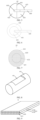
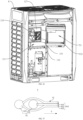
- FIG. 1 is a structural schematic view of an air conditioning system .
- the air conditioning system 1 may include a compressor 2, a four-way valve 3, an outdoor heat exchanger 4, an indoor heat exchanger 5, a heat exchanger 6, an expansion valve 12 and another expansion valve 13.
- the another expansion valve 13 and the heat exchanger 6 are disposed between the outdoor heat exchanger 4 and the indoor heat exchanger 5.
- the compressor 2 provides a circulating cooling medium flowing between the outdoor heat exchanger 4 and the indoor heat exchanger 5 through the four-way valve 3.
- a flowing path of the cooling medium in the first heat exchanging channel 610 (a primary path) is as follows: the first end of the first heat exchanging channel 610 - the second end of the first heat exchanging channel 610 - the indoor heat exchanger 5.
- a flowing path of the cooling medium in the second heat exchanging channel 611 (a secondary path) is as follows: the second end of the first heat exchanging channel 610 - the expansion valve 12 - the first end of the second heat exchanging channel 611 - the second end of the second heat exchanging channel 611 - the air intaking port 22 of the compressor 2.
- a working principle of the air conditioning system 1 may be as follows.
- the outdoor heat exchanger 4 serves as a condenser, and outputs a cooling medium having a medium pressure and a medium temperature (a liquid phase cooling medium having a temperature of 40°) via the another expansion valve 13.
- the cooling medium in the first heat exchanging channel 610 has a medium pressure and a medium temperature.
- the expansion valve 12 converts the cooling medium flow having the medium pressure and the medium temperature into a cooling medium having a low pressure and a low temperature (the cooling medium may be in a two phase of gas and liquid, and may have a temperature of 10°).
- the cooling medium in the second heat exchanging channel 611 may have a low pressure and a low temperature.
- the low-pressure and low-temperature cooling medium in the second heat exchanging channel 611 absorbs heat from the medium-pressure and medium-temperature cooling medium in the first heat exchanging channel 610, such that the cooling medium in the second heat exchanging channel 611 is gasified to sub-cool the cooling medium in the first heat exchanging channel 610.
- the gasified cooling medium in the second heat exchanging channel 611 blasts air to the compressor 2 to increase enthalpy, increasing a refrigerating capacity of the air conditioning system 1.
- the expansion valve 12 serves as a flow adjustment component for the second heat exchanging channel 611 and adjusts the amount of the cooling medium flowing in the second heat exchanging channel 611.
- Heat exchange may be performed between the cooling medium flowing in the first heat exchanging channel 610 and the cooling medium flowing in the second heat exchanging channel 611 to sub-cool the cooling medium flowing in the first heat exchanging channel 610. Therefore, the heat exchanger 6 may act as an economizer for the air conditioning system 1, increasing a degree of subcooling, further increasing a heat exchanging efficiency of the air conditioning system 1.
- connection port 31 of the four-way valve 3 is connected to the connection port 33, and the connection port 32 of the four-way valve 3 is connected to the connection port 34.
- the cooling medium output from air outputting port 21 of the compressor 2 flows from the indoor heat exchanger 5 to the outdoor heat exchanger 4 and takes the indoor heat exchanger 5 as the condenser.
- the cooling medium output from the indoor heat exchanger 5 is divided into two paths. For one of the two paths, the cooling medium enters the first heat exchanging channel 610 (the primary path). For the other one of the two paths, the cooling medium enters the second heat exchanging channel 611 (the secondary path) via the expansion valve 12.
- the cooling medium of the second heat exchanging channel 611 may sub-cool the cooling medium of the first heat exchanging channel 610.
- the cooling medium that flows through the second heat exchanging channel 611 supplies air for the compressor 2 to increase enthalpy to improve a heating capacity of the air conditioner.
- the heat exchanging body 61 may include a single plate body 613.
- the plate body 613 defines a plurality of micro-channels 612.
- the plurality of micro-channels 612 of the plate body 613 include first micro-channels 610 and second micro-channels 611, and the first micro-channels 610 and the second micro-channels 611 are arranged alternately.
- the first micro-channel 610 extends along an extension direction D1
- the second micro-channel 610 extends along an extension direction D2
- the extension direction D1 is parallel to the extension direction D2.
- the extension direction D1 of the first micro-channel 610 is the same as the extension direction D2 of the second micro-channel 611.
- the first cooling medium i.e., the cooling medium having the medium pressure and the medium temperature
- the second cooling medium i.e., the cooling medium having the low pressure and the low temperature
- the first cooling medium may be a liquid phase medium
- the second cooling medium may be a medium in two phases of liquid and gas. While the second cooling medium flowing along the second micro-channels 611, the second cooling medium absorbs heat from the first cooling medium flowing in the first micro-channels 610 to sub-cool the first cooling medium.
- a second micro-channel 611 is arranged between the two sets of the first micro-channels 610, and a first micro-channel 610 is arranged between the two sets of the second micro-channels 611, such that the at least two sets of the first micro-channels 610 are spaced apart from each other, and the at least two sets of the second micro-channels 611 are spaced apart from each other.
- the heat exchanger 6 having the first micro-channels 610 and the second micro-channels 611 arranged alternately may be formed, as shown in FIG. 2 .
- the first predetermined number and the second predetermined number may be equal, such as 3. In some embodiments, the first predetermined number may be different from the second predetermined number, such as the first predetermined number being 3, and the second predetermined number being 2.
- each of the first predetermined number and the second predetermined number may be 1.
- One of the plurality of micro-channels 612 is the first micro-channel 610, and one micro-channel that is arranged adjacent to the first micro-channel 610 may be the second micro-channel 611.
- the heat exchanging body 61 may have 10*10 micro-channels 612.
- An area of the cross section of the heat exchanging body 61 is the same as an area of a conventional channel.
- An equal mass and an equal amount of the cooling medium may flow through each of the 10*10 micro-channels 612 and the conventional channel.
- a characteristic length Dh of each of the 10*10 micro-channels 612 is 1/10 of a characteristic length of the conventional channel, and a pressure drop is proportional to L/(Dh2).
- a length L of the micro-channel 612 may be 1/100 of a length of the conventional channel.
- An effective heat exchanging area of the micro-channel 612 may be 1/10 of an effective heat exchanging area of the conventional channel.
- the amount of exchanged heat heat exchanging coefficient * a heat exchanging area
- the amount of exchanged heat of the micro-channel 612 may be equal to the amount of exchanged heat of the conventional channel. Therefore, when the length of the 10*10 micro-channels 612 may be 1/100 of the length of conventional channel, the micro-channels and the conventional channel may satisfy a same heat loading requirement.
- the heat exchanging body 61 defines the plurality of first micro-channels 610 and the plurality of second micro-channels 611 to reduce a length of the heat exchanging body 61.
- a size of the heat exchanger 6 may be reduced, and the amount of exchanged heat of the heat exchanger 6 may be the same as the amount of exchanged heat of the economizer.
- the plurality of micro-channels 612 may be configured as single-layered micro-channels or multi-layered micro-channels.
- an area of a cross section of the multi-layered micro-channels is four times of an area of a cross section of the single-layered micro-channel
- a length of the single-layered micro-channels is four times of a length of the multi-layered micro-channels.
- a flowing speed of the cooling medium in the multi-layered micro-channels may be 1/4 of a flowing speed of the cooling medium in the single-layered micro-channels.
- the larger the area of the cross section of the plurality of micro-channels 612, the shorter the length of the plurality of micro-channels 612, and a flow resistance loss of the cooling medium may be reduced.
- the pressure drop of the multi-layered micro-channel may be 1/48 of the pressure drop of the single-layered micro-channels.
- the heat exchanging coefficient has a functional relationship with the flowing speed of the cooling medium. The higher the flowing speed of the cooling medium, the greater the heat exchanging coefficient. Therefore, the amount of the exchanged heat of the single-layered micro-channels may be greater than the amount of the exchanged heat of the multi-layered micro-channels. In summary, when the amount of the exchanged heat can be satisfied, the area of the cross section of the plurality of micro-channels 612 may be larger to reduce the flow resistance loss of the cooling medium.
- the heat exchanger 6 may further include a fluid-collecting tube assembly 62.
- the fluid-collecting tube assembly 62 and the heat exchanger body 61 may be arranged horizontally.
- the fluid-collecting tube assembly 62 and the heat exchanger body 61 may be arranged along a horizontal plane.
- the fluid-collecting tube assembly 62 may be arranged vertically. That is, the fluid-collecting tube assembly 62 is arranged in a direction perpendicular to the horizontal plane (i.e., in a gravitational direction), and the heat exchanger body 61 is arranged horizontally.
- the fluid-collecting tube assembly 62 is arranged vertically, and the heat exchanger body 61 is arranged vertically.
- the fluid-collecting tube assembly 62 is arranged horizontally, and the heat exchanger body 61 is arranged vertically.
- the fluid-collecting tube assembly 62 may include a first fluid-collecting tube 621 and a second fluid-collecting tube 622.
- the first fluid-collecting tube 621 has a first fluid-collecting channel
- the second fluid-collecting tube 622 has a second fluid-collecting channel.
- the heat exchanger 6 has a cross section along a direction that the cooling medium (the first cooling medium or the second cooling medium) flows in the heat exchanging body 61, and the cross section is I shaped.
- the cross section may be L shaped, U shaped, G shaped, circular, and so on.
- the first fluid-collecting channel is communicated with the first micro-channel 610, such that the first cooling medium may be provided to the first micro-channel 610 through the first fluid-collecting channel; and/or the first cooling medium that flows through the first micro-channel 610 may be collected.
- two first fluid-collecting tubes 621 are arranged and are connected to two ends of the first micro-channel 610 respectively. In this way, the first cooling medium may be provided to the first micro-channel 610 through the one of the two first fluid-collecting tubes 621, and the first cooling medium that flows through the first micro-channel 610 may be collected through the other one of the two first fluid-collecting tubes 621.
- the first end of the first micro-channel 610 is connected to the outdoor heat exchanger 4 through one of the two first fluid-collecting tubes 621 via the expansion valve 13.
- the first cooling medium may be provided to the first micro-channel 610.
- the second end of the first micro-channel 610 is connected to the indoor heat exchanger 5 through the other one of the two first fluid-collecting tubes 621, such that the first cooling medium flowing through the first micro-channel 610 may be collected.
- functions of the two first fluid-collecting tubes 621 may be interchanged compared to the functions in the refrigerating mode.
- the second fluid-collecting channel is communicated with the second micro-channel 611, such that the second cooling medium may be provided to the second micro-channel 611 through the second fluid-collecting channel; and/or the second cooling medium that flows through the second micro-channel 611 may be collected.
- two second fluid-collecting tubes 622 are arranged and are connected to two ends of the second micro-channel 611 respectively. In this way, the second cooling medium may be provided to the second micro-channel 611 through the one of the two second fluid-collecting tubes 622, and the second cooling medium that flows through the second micro-channel 611 may be collected through the other one of the two second fluid-collecting tubes 622.
- the first end of the second micro-channel 611 is connected to the expansion valve 12 through one of the two second fluid-collecting tubes 622 to provide the second cooling medium to the second micro-channel 611.
- the second end of the second micro-channel 611 is connected to the air intaking port 22 of the compressor 2 through the other one of the two second fluid-collecting tubes 622 to collect the second cooling medium flowing through the second micro-channel 611.
- first micro-channels 610 and second micro-channels 611 same ends of the first micro-channels 610 are connected to one first fluid-collecting tube 621; and same ends of the second micro-channels 611 are connected to one second fluid-collecting tube 622. That is, the same ends of all first micro-channels 610 of the heat exchanger 6 are connected to one first fluid-collecting tube 621, and the same ends of all the second micro-channels 611 of the heat exchanger 6 are connected to one second fluid-collecting tube 622. In this way, a corresponding fluid-collecting tube may not be arranged for each of the all micro-channels, and costs may be reduced.
- an extension direction of the first fluid-collecting tube 621 is parallel to the extension direction of the second fluid-collecting tube 622.
- the extension directions of the first fluid-collecting tube 621 and the second fluid-collecting tube 622 may be adjusted based on the extension directions of the first micro-channel 610 and the second micro-channel 611.
- the extension direction of the first fluid-collecting tube 621 may be perpendicular to the extension direction of the second fluid-collecting tube 622.
- the first fluid-collecting tube 621 is spaced apart from the second fluid-collecting tube 622 along the extension direction of the heat exchanging body 61.
- the extension direction of the heat exchanging body 61 is the same as the extension direction D1 of the first micro-channel 610 and the extension direction D2 of the second micro-channel 611.
- the second micro-channel 611 extends through the first fluid-collecting tube 621 and is connected to the second fluid-collecting tube 622.
- the first fluid-collecting tube 621 is disposed between the second fluid-collecting tube 622 and the heat exchanging body 61.
- the second micro-channel 611 extends through the first fluid-collecting tube 621 and is inserted into and welded with the second fluid-collecting tube 622.
- the first micro-channel 610 is inserted into and welded with the first fluid-collecting tube 621.
- the first micro-channel 610 may extend through the second fluid-collecting tube 622 and is further inserted into the first fluid-collecting tube 621.
- the R is a diameter of a circumcircle of the first fluid-collecting tube 621 or a diameter of a circumcircle of the second fluid-collecting tube 622.
- the distance between the first fluid-collecting tube 621 and the second fluid-collecting tube 622 may be set to be large, such that the first fluid-collecting tube 621 may be easily welded to the heat exchanging body 61, and the second fluid-collecting tube 622 may be easily welded to the heat exchanging body 61.
- heat exchange is not performed between the second micro-channel 611, which is disposed between the first fluid-collecting tube 621 and the second fluid-collecting tube 622, and the first micro-channel 610.
- the length of the second micro-channel 611 disposed between the first fluid-collecting tube 621 and the second fluid-collecting tube 622 may be reduced, such that the heat exchanging area of the second micro-channel 611 may be increased.
- first fluid-collecting tube 621 and the second fluid-collecting tube 622 may be welded to reduce the distance between the first fluid-collecting tube 621 and the second fluid-collecting tube 622.
- first micro-channel 610 may be connected to the first fluid-collecting tube 621 by avoiding the second fluid-collecting tube 622.
- first micro-channel 610 may be arranged at an outside of the second fluid-collecting tube 622, such that the first micro-channel 610 may be connected to the first fluid-collecting tube 621 by avoiding the second fluid-collecting tube 622.
- second micro-channel 611 may be connected to the second fluid-collecting tube 622 by avoiding the first fluid-collecting tube 621.
- the fixing bracket 73 may be connected between the first extension portion 617 and the circumferential side plate 724.
- the fixing bracket 73 may be connected between the second extension portion 618 and the circumferential side plate 724.
- Connection structures of the above two arrangements may substantially be the same.
- the fixing bracket 73 being connected between the first extension portion 617 and the circumferential side plate 724 may be taken as an example to illustrate the connection structure of the heat exchanging body 61 and the box body 72.
- the fixing bracket 73 may include a first fixing portion 731 and a second fixing p portion art 732.
- the first fixing portion 731 may bend towards the second fixing p portion art 732.
- the first fixing portion 731 may be welded to the first extension portion 617, and the second fixing portion 732 may be fastened to the circumferential side plate 724.
- the first fixing portion 731 may be welded to one of main surfaces of the heat exchanging body 61 to increase a welding area between the fixing bracket 73 and the heat exchanging body 61, improving a welding strength.
- the first fixing portion 731 may not need to define any hole, such that the micro-channels defined in the heat exchanging body 61 may not be interrupted.
- the second fixing portion 732 may be connected to the circumferential side plate 724 by screws, snaps or glue, such that the heat dissipation member 6 may be maintained or replaced easily.
- the main surface of the heat exchanging body 61 refers to a surface of the heat exchanging body 61 having a large area. In this embodiment, as shown in FIG. 10 , the main surface of the heat exchanging body 61 refers to a surface parallel to the XOZ plane.
- the second fixing portion 732 is connected vertically to the first fixing portion 731, such that an L-shaped fixing bracket 73 may be formed.
- first fixing portion 731 vertically to the second fixing portion 732, forces applied to the fixing bracket 73 may be evenly distributed on the fixing bracket 73.
- the fixing bracket 73 may include a first fixed portion 731, a second fixed portion 732 and a third fixed portion 733.
- the first fixed portion 731, a second fixed portion 732 and a third fixed portion 733 may be connected with each other, and a connection part between any two of the portions may be bent.
- the first fixed portion 731 and the third fixed portion 733 may be spaced apart from each other and connected to the bottom plate 723.
- the second fixed portion 732 and the bottom plate 723 may be spaced apart from each other to cooperatively define a clamping slot 734.
- the first extension portion 617 may be welded to a side of the second fixed portion 732 away from the clamping slot 734.
- the heat exchanging body 61 may be spaced apart from the bottom plate 723, such that the contact between the heat exchanging body 61 and the electric control box 7 may be interrupted, heat exchanging between the heat exchanging body 61 and the electric control box 7 may be avoided, and the heat dissipation efficiency of the heat dissipation member 6 may not be reduced.
- first fixed portion 731 and the third fixed portion 733 may be bent towards and connected to opposite ends of the second fixed portion 732 and may be disposed on a same side of the second fixed portion 732, such that a clamping slot 734 in a C shape may be defined.
- An end of the first fixed portion 731 away from the second fixed portion 732 and an end of the third fixed portion 733 away from the second fixed portion 732 may be connected to the bottom plate 723.
- the connection manner between the second fixing portion 732 and the heat exchanging body 61 may be the same as and may be referred to the embodiments described in the above.
- the connection manner that the first fixing portion 731 and the third fixing portion 733 are connected to the bottom plate 723 may be the same as and may be referred to the embodiments described in the above. The connection manners will not be repeated herein.
- the first extension portion 617 may be clamped in the clamping slot 734.
- the first extension portion 617 may abut against the bottom plate 723 and the second fixing portion 732 on two opposite sides along the overall width direction of the heat exchanging body 61.
- the first extension portion 617 may abut against the first fixing portion 731 and the third fixing portion 733 on two opposite sides along the overall height direction of the heat exchanging body 61. In this way, the first extension portion 617 may be fixed.
- the heat exchanging body 61 may be fixed by being clamped, such that the heat exchanging body 61 may not be damaged, and the heat exchanging body 61 may be easily repaired or replaced.
- any ordinary skilled person in the art shall understand that, the above-mentioned fixing brackets may be applied to fix the heat dissipation members in any forms as disclosed herein, and a position wherein the heat dissipation member is fixed may not be limited herein.
- the heat dissipation member 6 is received in the mounting cavity 721 of the electric control box 7.
- the heat dissipation member 6 may be thermal-conductively connected to the electronic element 71 received in the mounting cavity 721 to dissipate heat from the electronic element 71.
- the electronic element 71 may be thermal-conductively connected to the first extension portion 617 and/or the second extension portion 618.
- the heat dissipation members in any forms as disclosed herein may be received inside the mounting cavity 721 of the electric control box 7 or applied to dissipate heat from the electric control box 7, and may be directly or indirectly thermal-conductively connected to the electronic element 71.
- the electronic element 71 may be thermal-conductively connected to the first extension portion 617.
- the electronic element 71 and the second extension portion 618 may be arranged on a same side of the first extension portion 617, such that the height of the electric control box 7, i.e., a size along the Y direction, may be reduced,
- the electronic element 71 may be thermal-conductively connected to the second extension portion 618, and may be arranged on a side of the second extension portion 618 facing towards the first extension portion 617, such that the length of the electric control box 7, i.e., a size along the X direction, may be reduced.
- a part of the electronic element 71 may be arranged on the first extension portion 617, and another part of the electronic element 71 may be arranged on the second extension portion 618, such that the electronic element 71 may be evenly distributed.
- the number of electronic elements 71 may be large, connecting each of the large number of the electronic elements 71 to the heat exchanging body 61 may cause the electronic elements 71 to be mounted in a complicated manner, and the mounting efficiency may be low.
- a heat dissipation fixing plate 74 may be arranged inside the electric control box 7.
- the electronic elements 71 may be arranged on the heat dissipation fixing plate 74.
- the heat dissipation fixing plate 74 may be arranged on the heat exchanging body 61, such that the electronic elements 71 may be thermal-conductively connected to the heat exchanging body 61 through the heat dissipation fixing plate 74. In this way, the efficiency of mounting the electronic elements 71 may be greatly improved.
- the heat dissipation fixing plate 74 may be arranged on the first extension portion 617 and/or the second extension portion 618, and the electronic elements 71 may be arranged on a side of the heat dissipation fixing plate 74 away from the first extension portion 617 and/or the second extension portion 618.
- the heat dissipation fixing plate 74 may be arranged on the main surface of the heat exchanging body 61 to increase the contact area between the heat dissipation fixing plate 74 and the heat exchanging body 61, such that the heat exchanging efficiency may be improved.
- the main surface of the heat exchanging body 61 may provide a larger support surface for the heat dissipation fixing plate 74, and therefore, the electronic elements 71 may be arranged more stably.
- the heat dissipation fixing plate 74 may be made of metal or alloy having better thermal conductivity.
- the heat dissipation fixing plate 74 may be made of aluminum, copper, aluminum alloy, and so on, to enhance the efficiency of heat conductivity.
- the heat pipe 741 may be long-strip shaped.
- a plurality of heat pipes 741 may be arranged.
- the plurality of heat pipes 741 may be arranged in parallel and spaced apart from each other.
- the plurality of heat pipes 741 may be connected successively to each other to form a square or a frame, which will not be limited by the present application.
- the heat dissipation member 6 may be arranged on an outside of the electric control box 7.
- the box body 72 of the electric control box 7 may define an assembly port 726, and the electronic elements 71 may be thermal-conductively connected to the heat dissipation member 6 through the assembly port 726.
- the heat dissipation fixing plate 74 may be connected to the heat dissipation member 6 and cover the assembly port 726.
- the electronic elements 71 may be arranged on a surface of the heat dissipation fixing plate 74 away from the heat dissipation member 6.
- the heat pipe 741 may be arranged to enable the electronic elements 71 to be thermal-conductively connected to the heat dissipation member 6.
- the heat pipe 741 may include a heat absorbing end 741a and a heat releasing end 741b.
- the heat absorbing end 741a of the heat pipe 741 may be inserted inside the mounting cavity 721 and thermal-conductively connected to the electronic elements 71 to absorb heat from the electronic elements 71.
- the heat releasing end 741b of the heat pipe 741 may be arranged on the outside of the electric control box 7 and thermal-conductively connected to the heat dissipation member 6, taking the heat dissipation member 6 to dissipate heat from the heat releasing end 741b of the heat pipe 741.
- a large amount of heat may be generated while the electronic elements 71 are operating, and the electric control box 7 may be relatively sealed.
- a temperature in the mounting cavity 721 of the electric control box 7 may be high. Therefore, the electronic elements 71 may be damaged.
- the cooling medium flowing in the heat dissipation member 6 arranged inside the mounting cavity 721 may take away some of the heat, the heat dissipation performance of the electric control box 7 may still be poor.
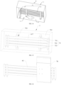
- a heat dissipation fin 75 may be arranged inside the electric control box 7.
- the heat dissipation fin 75 may be thermal-conductively connected to the heat exchanging body 61, such that the contact area between the heat exchanging body 61 and the air in the electric control box 7 may be increased due to the heat dissipation fin 75, heat exchanging with the air may be improved, the temperature in the mounting cavity 721 may be reduced, and the electric elements 71 may be protected.
- one of the electronic element 71 and the heat dissipation fin 75 may be arranged on the first extension portion 617, and the other one of the electronic element 71 and the heat dissipation fin 75 may be arranged on the second extension portion 618, such that the electronic element 71 may be misaligned with the heat dissipation fin 75, and the electronic element 71 may not be interfered by the heat dissipation fin 75. Further, the distance between the electronic element 71 and the heat dissipation fin 75 may be large, such that the temperature of the cooling medium that contacts the heat dissipation fin 75 and the electronic element 71 may be low, and the heat dissipation effect of the heat exchanging body 61 may be improved.
- one heat dissipation fin 75 may be arranged.
- a size of the heat dissipation fin 75 in the overall height direction of the heat exchanging body 61 may be greater than the overall height of the heat exchanging body 61.
- the heat dissipation fin 75 may be connected to the surface of the heat exchanging body 61 by welding, bonding or fastening.
- a smaller number of heat dissipation fins 75 may be arranged, and the arranged heat dissipation fin 75 may have a large surface area.
- the heat dissipation fin 75 may be easily connected to the heat exchanging body 61, improving the efficiency of arranging the heat dissipation fin 75 and the heat exchanging body 61.
- the contact area between the heat dissipation fin 75 and the air may be increased, improving the heat exchanging effect.
- a plurality of heat dissipation fins 75 may be arranged.
- a size of each of the plurality of heat dissipation fins 75 along the overall height direction of the heat exchanging body 61 may be equal to a size of each plate body along the overall height direction of the heat exchanging body 61.
- Each of the plurality of heat dissipation fins 75 may be attached to one plate body.
- the plurality of heat dissipation fins 75 may be spaced apart from each other and arranged along the overall height direction of the heat exchanging body 61, such that the contact area of the heat dissipation fins 75 and the air may be increased. Since the plurality of heat dissipation fins 75 are arranged and are spaced apart from each other, the heat exchanging efficiency of the heat dissipation fins 75 may be ensured, manufacturing materials may be saved, and production costs may be reduced.
- the heat dissipation fin 75 may be extended to the outside of the electric control box.
- the assembly port may be defined in the box body 72
- the heat exchanging body 61 may be arranged inside the box body 72 and thermal-conductively connected to the electronic elements 71.
- a side of the heat dissipation fin 75 may be thermal-conductively connected to the heat exchanging body 61 and extends to the outside of the box body 72 through the assembly port, and air cooling may be applied to improve the heat dissipation effect of the heat exchanging body 61.
- any ordinary skilled person in the art shall understand that the above heat dissipation fin may be applicable to the heat exchangers in any forms as described herein, and shall not be limited to a particular embodiment.
- the structure of the heat dissipation member 6 is substantially the same as that of the heat dissipation member 6 in the above embodiments.
- the heat dissipation member 6 further includes a third extension portion 619.
- the first extension portion 617 and the third extension portion 619 are arranged side by side and are spaced apart from each other.
- the second extension portion 618 is connected between an end of the first extension portion 617 and an end of the third extension portion 619 adjacent to the end of the first extension portion 617.
- the third extension portion 619 is connected to an end of the second extension portion 618 away from the first extension portion 617 and is bent towards a side of the second extension portion 618 facing towards the first extension portion 617, such that the third extension portion 619 may be spaced apart from the first extension portion 617.
- the overall length and the overall width of the heat exchanging body 61 may be reduced to further reduce the size of the electric control box 7 that is engaged with the heat dissipation member 6.
- two second extension portions 618 are arranged.
- the two second extension portions 618 are bent towards and connected to two opposite ends of the first extension portion 617.
- One third extension portion 619 is arranged.
- the third extension portion 619 is arranged at an end of one of the two second extension portions 618 away from the first extension portion 617 and is towards the other one of the two second extension portions 618, such that a G-shaped heat exchanging body 61 is formed.
- two second extension portions 618 are arranged. One of the two second extension portions 618 is bent towards and connected to one of two ends of the first extension portion 617. One third extension portion 619 is arranged. The third extension portion 619 is arranged at an end of the second extension portion 618 away from the first extension portion 617 and is bent towards the first extension portion 617.
- two second extension portions 618 are arranged.
- the two second extension portions 618 are bent towards and connected to two opposite ends of the first extension portion 617.
- Two third extension portions 619 are arranged.
- the two third extension portions 619 are connected to ends of the two second extension portions 618 away from the first extension portion 617 and are extending towards each other, such that the overall length of the heat exchanging body 61 may further be reduced.
- heat dissipation fixing plate 74 may be fixed to the third extension portion 619 in addition to the first extension portion 617 and/or the second extension portion 618 in the manner as described in the above embodiments.
- the air conditioning system 1 is in the refrigerating mode.
- the cooling medium output from the compressor 2 flows to the outdoor heat exchanger 4 for heat exchanging.
- the cooling medium continues flowing to the flow adjustment valve (the expansion valve 13), and further flows through the third unidirectional guiding member 703 to enter the fluid-collecting tube assembly 62 near the first end 61a. Further, the cooling medium flows through the heat exchanging body 61 to reach the second end 61b. In this way, in the direction from the first end 61a to the second end 61b, heat exchanging may occur between the cooling medium and the secondary channel (i.e., the cooling medium may be sub-cooled). In this way, the temperature of the heat exchanging body 61 decreases in the direction from the first end 61a to the second end 61b.
- the cooling medium flowing from the second end 61b may flow through the second unidirectional guiding member 702 to reach the indoor heat exchanger 5 for heat exchanging.
- the air conditioning system 1 is in the heating mode.
- the cooling medium output from the compressor 2 flows to the indoor heat exchanger 5 for heat exchanging.
- the cooling medium continues flowing to the electric control box 7, and further flows through the first unidirectional guiding member 701 to enter the fluid-collecting tube assembly 62 near the first end 61a. Further, the cooling medium flows through the heat exchanging body 61 to reach the second end 61b. In this way, in the direction from the first end 61a to the second end 61b, heat exchanging may occur between the cooling medium and the secondary channel (i.e., the cooling medium may be sub-cooled). In this way, the temperature of the heat exchanging body 61 decreases in the direction from the first end 61a to the second end 61b.
- the cooling medium flowing from the second end 61b may flow through the fourth unidirectional guiding member 704 to reach the outdoor heat exchanger 4 for heat exchanging.
- each of the first unidirectional guiding member 701, the second unidirectional guiding member 702, the third unidirectional guiding member 703 and the fourth unidirectional guiding member 704 may be configured as a one-way valve. In some embodiments, each of the first unidirectional guiding member 701, the second unidirectional guiding member 702, the third unidirectional guiding member 703 and the fourth unidirectional guiding member 704 may be configured as an electromagnetic valve. The present disclosure does not limit a type of the unidirectional guiding member.
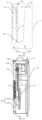
- the electric control box 7 in the present embodiment includes a box body 72, a mounting plate 76, an electronic element 71 and a heat dissipation member 6.
- the box body 72 defines a mounting cavity 721, and the mounting plate 76 is received in the mounting cavity 721, such that the mounting cavity 721 is divided into a first cavity 7212 and a second cavity 7214 located on two sides of the mounting plate 76.
- the electronic element 71 is received in the second cavity 7214.
- At least a part of the heat exchanging body 61 is received in the first cavity 7212 and is thermal-conductively connected to the electronic element 71.
- the mounting plate 76 is configured to prevent the condensed water on the heat dissipation member 6 from flowing into the second cavity 7214.
- the heat dissipation fixing plate 74 may be arranged to indirectly connect the electronic v 71 to the heat exchanging body 61.
- the mounting plate 76 may define an avoidance hole 762 at a position corresponding to the heat dissipation fixing plate 74.
- the heat dissipation fixing plate 74 is connected to the heat exchanging body 61 and blocks the avoidance hole 762.
- the electronic element 71 is arranged on a side of the heat dissipation fixing plate 74 away from the heat exchanging body 61.
- the heat dissipation fixing plate 74 may be configured to enable the electronic element 71 to be thermal-conductively connected to the heat exchanging body 61.
- the heat dissipation fixing plate 74 may be configured to separate the first cavity 7212 from the second cavity 7214. Therefore, the condensed water may be prevented from flowing through the avoidance hole 762 to reach the second cavity 7214 in which the electronic element 71 is arranged, such that the condensed water may be prevented from contacting the electronic element 71.
- the condensed water may be accumulated and fall due to the gravitational force.
- the dropped condensed water may generate noise, and condensed water, which is spreadly distributed, may not be discharged out of the electric control box 7 easily.
- a guiding plate 77 is arranged inside the electric control box 7.
- the guiding plate 77 may be arranged on a lower side of the heat dissipation member 6 to collect the condensed water dripping from the heat dissipation member 6.
- a height that the condensed water drops may be reduced, such that the noise may be reduced.
- the guiding plate 77 may accumulate the condensed water, such that the condensed water may be accumulated and further discharged out of the electric control box 7.
- the heat dissipation member 6 is fixed to the bottom plate 723 of the electric control box 7.
- An end of the guiding plate 77 is connected to the bottom plate 723, and the other end of the guiding plate 77 extends towards an interior of the first cavity 7212. Further, a projection of the heat dissipation member 6 along the vertical direction locates in the guiding plate 77. In this way, the condensed water from the heat dissipation member 6 drops to reach the guiding plate 77, preventing the condensed water from dropping to reach other locations of the electric control box 7.
- the heat dissipation member 6 may be arranged on the mounting plate 76.
- an end of the guiding plate 77 is connected to the mounting plate 76, and the other end of the guiding plate 77 extends towards the interior of the first cavity 7212. Further, the projection of the heat dissipation member 6 along the vertical direction is located in the guiding plate 77.
- a drainage hole 725 may be defined in a bottom wall of the box body 72, and the guiding plate 77 may be inclined at a certain angle with respect to the bottom wall of the box body 72. The condensed water is guided by the guiding plate 77 and discharged from the box body 72 through the drainage hole 725.
- the drainage hole 725 may be defined in the circumferential side plate 724 of the electric control box 7.
- the guiding plate 77 is connected to the mounting plate 76 or the bottom plate 723 of the box body 72 and is inclined towards the drainage hole 725. After the condensed water drops on the guiding plate 77, the condensed water may flow along the inclined guiding plate 77 to be collected at the position where the drainage hole 725 is defined, and may be drained out of the electric control box 7 from the drainage hole 725.
- the number and sizes of drainage holes 725 may be determined flexibly based on the amount of condensed water, and will not be limited herein.
- the flowing direction of the cooling medium in the heat exchanging body 61 may be configured to be the horizontal direction. That is, the extension direction of the heat exchanging body 61 may be the horizontal direction.
- a path that the condensed water flows in the heat exchanging body 61 may be reduced, such that the condensed water may drop down to the guiding plate 77 due to the gravitational force as soon as possible, enabling the condensed water to be discharged out of the electric control box 7 in time, preventing the condensed water from contacting the electronic element 71 arranged inside the mounting cavity 721.
- the guiding plate 77 may be prevented from interfering with the heat exchanging body 61, such that a relatively long heat exchanging body 61 may be arranged, improving the heat exchanging efficiency of the heat dissipation member 6.
- the electric control box 7 in an embodiment in accordance with this invention includes a box body 72, a mounting plate 76 and a heat dissipation member 6.
- the box body 72 defines a mounting cavity 721, and the mounting plate 76 is received in the mounting cavity 721, such that the mounting cavity 721 is divided into a first cavity 7212 and a second cavity 7214 located on two sides of the mounting plate 76.
- the mounting plate 76 defines a first air vent 764 and a second air vent 766.
- the first air vent 764 and the second air vent 766 are spaced apart from each other. In this way, gas in the first cavity 7212 flows into the second cavity 7214 via the first air vent 764 and gas in the second cavity 7214 flows into the first cavity 7212 via the second air vent 766. At least a part of the heat exchanging body 61 is received in the first cavity 7212.
- a flowing direction of a part of the cooling medium in the heat exchanging body 61 is configured to be a direction that the first air vent 764 is spaced apart from the second air vent 766.
- the temperature of the heat exchanging body 61 gradually increases in the direction from the second air vent 766 to the first air vent 764. That is, a temperature of a position of the heat exchanging body 61 near the first air vent 764 is higher than a temperature of a position of the heat exchanging body 61 near the second air vent 766.
- the cooling medium herein may be the cooling medium in the primary channel or in the secondary channel in the air conditioning system shown in FIG. 1 .
- the heat exchanging body 61 may be arranged in the horizontal direction, in the vertical direction or in other directions, which will not be limited herein.
- the number, positions and extension directions of first air vents 764 and second air vents 766 are not limited herein.
- the mounting plate 76 is arranged inside the electric control box 7 and defines the first air vent 764 and the second air vent 766 along the flowing direction of the cooling medium, and the first air vent 764 may be spaced apart from the second air vent 766.
- the air may contact the condensed water, and the condensed water may be vaporized. In this way, on one hand, the condensed water may be prevented from being accumulated, and drainage structures may be omitted.
- the condensed water may be vaporized and absorb heat to reduce the temperature of the heat dissipation member 6.
- the temperature of the cooling medium in the heat dissipation member 6 may be reduced, and the heat exchanging performance of the heat dissipation member 6 may be improved.
- the flowing direction of the cooling medium in the heat exchanging body 61 is configured to be a direction that the first air vent 764 is spaced apart from the second air vent 766.
- the flowing direction of the cooling medium may be parallel to or may be at a certain angle relative to direction that the first air vent 764 is spaced apart from the second air vent 766.
- the air conditioners since the air conditioners generally have the refrigerating mode and the heating mode, the flowing direction of the cooling medium in the refrigerating mode may be opposite to the flowing direction of the cooling medium in the heating mode. Therefore, the priority is given to the refrigerating mode, the temperature of the heat exchanging body 61 is ensured to increase gradually in the direction from the second air vent 766 to the first air vent 764. Reasons will be explained in the following.
- the ambient temperature is low, for example, when the air conditioning apparatus is operating to heat the environment in winter, the temperature of the air inside the electric control box 7 is low, the temperature difference between the air inside the electric control box 7 and the heat dissipation member 6 is small. The air may not be condensed into water easily.
- the ambient temperature is high, for example, when the air conditioning apparatus is operating to cool the environment in summer, the temperature of the air in the electric control box 7 is high, and the temperature difference between the air in the electric control box 7 and the heat dissipation member 6 is high. Therefore, the air may be easily condensed into water.
- the temperature of the heat exchanging body 61 may gradually increase in the direction from the second air vent 766 to the first air vent 764, preventing the condensed water from being generated on the heat dissipation member 6 in the refrigerating mode.
- the electric control box 7 may further include an electronic element 71, and the electronic element 71 is thermal-conductively connected to the heat dissipation member 6, such that heat may be dissipated from the electronic element 71 by the heat dissipation member 6.
- the electronic element 71 may be received in the first cavity 7212. In order to reduce the possibility that the electronic element 71 contacts the condensed water, the electronic element 71 may be arranged at a position of the heat exchanging body 61 near the first air vent 764 and may be thermal-conductively connected to the heat exchanging body 61.
- the temperature of the air gradually decreases. Further, the temperature of the heat exchanging body 61 near the first air vent 764 is high, and therefore, the temperature difference between the air and the heat dissipation member 6 may be reduced to reduce a possibility that the air is condensed at the position of the heat exchanging body 61 near the first air vent 764.
- the electronic element 71 is arranged at the position of the heat exchanging body 61 near the first air vent 764. In this way, the electronic element 71 may be prevented from contacting condensed water, and the electronic element 71 arranged on the heat exchanging body 61 may be protected.
- the first air vent 764 and the second air vent 766 may be spaced apart from each other along the horizontal direction.
- the extension of the heat exchanging body 61 may be along the horizontal direction.
- the condensed water may flow down in the vertical direction. Since the length of the heat exchanging body 61 in the vertical direction is small, the condensed water may leave the heat exchanging body 61 after flowing for a certain distance, resulting in the condensed water being dropped.
- the first air vent 764 and the second air vent 766 may be spaced apart from each other along the vertical direction, the first air vent 764 is arranged at an upper of the second air vent 766, and the extension direction of the heat exchanging body 61 may be the vertical direction.
- the condensed water may flow along the vertical direction.
- the first air vent 764 is arranged at the upper of the second air vent 766, and the electronic element 71 is arranged at the position near the first air vent 764, such that the condensed water may flow in a direction away from the electronic element 71, and the electronic element 71 may be prevented from contacting the condensed water.
- a cooling fan 78 may be arranged inside the electric control box 7 to increase the air ventilation effect of the first cavity 7212 and the second cavity 7214.
- the cooling fan 78 may be received in the second cavity 7214.
- the cooling fan 78 in the second cavity 7214 may provide a forced ventilation enables the air to flow from the second air vent 766 to the first cavity 7212.
- the heat generated while the electronic element 71 is operating may enable the temperature in the second cavity 7214 to be higher than the temperature in the first cavity 7212.
- the speed that the high temperature air flows from the second air vent 766 to the first cavity 7212 may be increased in order to enhance the speed that the condensed water is vaporized.
- the cooling fan 78 may be arranged at the position near the first air vent 764 to increase a distance between the cooling fan 78 and the second air vent 766, increasing an operating range of the cooling fan 78, such that the cooling fan 78 may drive more air to flow into the second air vent 766.
- a temperature sensor (not shown in the drawings) may be arranged inside the electric control box 7.
- the temperature sensor may be configured to detect the temperature in the second cavity 7214. In this way, when the temperature sensor detects that the temperature in the second cavity 7214 is greater than a temperature threshold, the cooling fan 78 may be controlled to start operating, or an operating speed of the cooling fan 78 may be increased.
- the value of the temperature threshold may be determined as required and will not be limited by the present disclosure.
- the electronic element 71 and the heat dissipation fin 75 are spaced apart from each other along the flowing direction of the cooling medium of the heat exchanging body 61.
- the space on the heat exchanging body 61 may be optimally utilized.
- the heat exchanging body 61 may dissipate heat from the electronic element 71.
- the heat dissipate fin 75 may be configured to reduce the temperature in the mounting cavity 721 of the electric control box 7, such that the electronic elements 71 arranged inside the mounting cavity 721 may be protected.
- the temperature of the first end 61a may be higher than the temperature of the second end 61b. Since a temperature difference between the higher temperature first end 61a and the hot air in the mounting cavity 721 is relatively small, the condensed water may be less likely generated. Therefore, the electronic element 71 may be arranged near the first end 61a, i.e., the first position is a position near the first end 61a. Since a temperature difference between the lower temperature second end 61b and the hot air in the mounting cavity 721 is relatively large, the condensed water may be more likely generated.
- the heat dissipation fin 75 may be arranged near the second end 61b.
- the lower temperature of the heat dissipation fin 75 may allow the temperature difference between the heat dissipation fin 75 and the hot air to be large, such that the heat may be dissipated from the electric control box 7.
- the condensed water formed on the heat dissipation fin 75 may be vaporized due to the hot air. Evaporation of the condensed water may absorb heat to further reduce the temperature of the cooling medium, improving the heat exchanging effect of the heat dissipation member 6.
- the cooling fan 78 is arranged inside the electric control box 7.
- the cooling fan 78 is configured to generate a heat dissipation airflow on the heat dissipation fin 75 in the electric control box 7. In this way, the flowing speed of the heat dissipation airflow may be increased, improving the heat exchanging effect.
- the cooling fan 78 may be arranged at a position near the heat dissipation fin 75 to act directly on the heat dissipation fin 75.
- the mounting plate 76 is arranged inside the electric control box 7.
- the mounting plate 76 is received in the mounting cavity 721, such that the mounting cavity 721 is divided into the first cavity 7212 and the second cavity 7214, and the first cavity 7212 and the second cavity 7214 are located on two sides of the mounting plate 76, respectively.
- the mounting plate 76 defines the first air vent 764 and the second air vent 766 spaced apart from the first air vent 764, such that the gas in the first cavity 7212 flows into the second cavity 7214 through the first air vent 764, and the gas in the second cavity 7214 flows into the first cavity 7212 through the second air vent 766.
- At least a part of the heat exchanging body 61 is received in the first cavity 7212, and the electronic element 71 and the cooling fan 78 are received in the second cavity 7214.
- the mounting plate 76 is configured to divide the mounting cavity 721 into two independent cavities, the first cavity 7212 and the second cavity 7214, and a circulating airflow may be generated in the first cavity 7212 and the second cavity 7214. Therefore, the amount of air that contacts the heat dissipation fin 75 received in the first cavity 7212 may be increased, and cooled air may dissipate heat from the electronic element 71 received in the second cavity 7214, airflows may not be mixed, and the heat dissipation efficiency of the heat dissipation fin 75 may be improved.
- the cooling fan 78 received in the second cavity 7214 is configured to increase the flowing speed of the air in the second cavity 7214, such that the speed that the air circulates between the first cavity 7212 and the second cavity 7214 may be increased, and the efficiency of dissipating heat from the electric control box 7 may be increased.
- a direction that the heat dissipation air flows along the heat dissipation fin 75 may be configured to be perpendicular to the flowing direction of the cooling medium.
- the heat dissipation air when the cooling medium in the heat exchanging body 61 is flowing in the horizontal direction, the heat dissipation air may be configured to flow in the vertical direction, such that the heat dissipation air may not flow to the position where the electronic element 71 is arranged.
- first air vent 764 and the second air vent 766 may be spaced apart from each other along the vertical direction and are disposed on opposite sides of the heat dissipation fin 75.
- the number and an arrangement density of first air vents 764 and the number and an arrangement density of second air vents 766 may be determined based on demands.
- the heat dissipation air when the cooling medium in the heat exchanging body 61 is flowing in the vertical direction, the heat dissipation air may be configured to flow in the horizontal direction, such that the heat dissipation air may not flow to the position where the electronic element 71 is arranged.
- the flowing direction of the heat dissipation air and the flowing direction of the cooling medium may be along another two perpendicular directions, which will not be limited by the present disclosure.
- the first air vent 764 and the second air vent 766 are arranged in the vertical direction, the first air vent 764 may be arranged at an upper of the second air vent 766, such that the hot air entering the first cavity 7212 through the second air vent 766 may automatically flow to the position where the heat exchanging body 61 is arranged, and heat exchanging may occur between the hot air and the heat exchanging body 61.
- the cooling fan 78 may be arranged at the position near the first air vent 764, such that cold air located at a top of the first cavity 7212 may enter the second cavity 7214 in time, and the cooling fan 78 may accelerate the cold air to increase the efficiency of dissipating heat from the electronic element 71.
- a heat dissipation hole may be defined in the box body 72 of the electric control box 7 and may be communicated with the mounting cavity 721, such that the air inside the box may be circulated with the air out of the box to achieve heat exchanging, and the electric control box 7 may be cooled down.
- the box body 72 defines the heat dissipation hole, air tightness of the electric control box 7 may be reduced, impurities, such as water and dust at the outside of the box, may enter the mounting cavity 721 through the heat dissipation hole, such that the electronic element arranged in the mounting cavity 721 may be damaged.
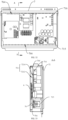
- the box body 72 of the electric control box 7 may be configured as a sealed box body.
- the electric control box 7 may include the box body 72, the mounting plate 76, the heat dissipation member 6, the electronic element 71 and the cooling fan 78.
- the box body 72 defines the mounting cavity 721.
- the mounting plate 76 is received in the mounting cavity 721, such that the mounting cavity 721 is divided into the first cavity 7212 and the second cavity 7214, and the first cavity 7212 and the second cavity 7214 are located on two sides of the mounting plate 76, respectively.
- the mounting plate 76 defines the first air vent 764 and the second air vent 766 spaced apart from the first air vent 764.
- the first air vent 764 and the second air vent 766 are communicated with the first cavity 7212 and the second cavity 7214.
- At least a part of the heat exchanging body 61 is received in the first cavity 7212, and the electronic element 71 is received in the second cavity 7214 and is thermal-conductively connected to the heat dissipation member 6.
- the cooling fan 78 is configured to supply air, such that the gas in the first cavity 7212 flows into the second cavity 7214 through the first air vent 764.
- the heat dissipation member 6 is received in the first cavity 7212, and the electronic element 71 and the cooling fan 78 are received in the second cavity 7214.
- the mounting plate 76 defines the first air vent 764 and the second air vent 766 spaced apart from the first air vent 764, and the first air vent 764 and the second air vent 766 are communicated with the first cavity 7212 and the second cavity 7214.
- the heat generated by the electronic element 71 causes the air in the second cavity 7214 to be increased
- the cooling fan 78 drives the hot air to flow into the second air vent 766. Since the hot air has a low density, the hot air may flow upwardly to contact the heat dissipation member 6 received in the first cavity 7212.
- the heat dissipation member 6 may cool the hot air into cold air.
- the cold air flows into the second cavity 7214 through the first air vent 764.
- the cooling fan 78 is configured to accelerate the flowing speed of the cold air. In this way, the cold air may be taken to cool the electronic element 71 received in the second cavity 7214.
- a temperature of the cold air, which exchanges heat with the electronic element 71, may be increased, and the cold air, which has the increased temperature, may be driven by the cooling fan 78 to enter the second air vent 766.
- the above circulation may occur periodically. In this way, the internal circulation may be generated to cool the electronic element 71 received in the electric control box 7.
- the electric control box 7 may be completely sealed, such that waterproof, insect-proof, dust-proof and moisture-proof may be achieved, and the reliability of the electric control box 7 may be improved.
- the cooling fan 78 is mounted in the first air vent 764.
- a plane in which the cooling fan 78 is located may be coplanar with a plane in which the mounting plate 76 is located.
- the cooling fan 78 may be fixedly arranged in the first air vent 764 by a fan bracket (not shown in the drawings).
- the plane in which the cooling fan 78 is located may refer to a plane perpendicular to a direction of a rotational axis of the cooling fan 78. Since the cooling fan 78 is arranged in the first air vent 764, a distance between the cooling fan 78 and the first cavity 7212 may be reduced, such that the cold air may be easily discharged out of the first cavity 7212. Further, the cooling fan 78 may not occupy any space of the second cavity 7214, such that elements inside the electric control box 7 may be arranged more compact, and the size of the electric control box 7 may be reduced.
- the electronic element 71 is usually arranged on the mounting plate 76. Therefore, when the plane in which the cooling fan 78 is located is coplanar with the plane in which the mounting plate 76 is located, the flowing direction of the air of the cooling fan 78 may be perpendicular to the plane in which the mounting plate 76 is located. In this way, the flowing direction of the air of the cooling fan 78 may not act directly on the electronic element 71, and a path that the air flows in the second cavity 7214 may be increased.
- an air guiding cover 79 may be arranged inside the electric control box 7.
- the air guiding cover 79 may be arranged to cover a periphery of the cooling fan 78 and configured to guide the air blown by the cooling fan 78, such that the air blown from the cooling fan 78 may be directed towards the electronic element 71.
- the air guiding cover 79 is connected to the mounting plate 76.
- An air outlet of the air guiding cover 79 faces towards the position where the electronic element 71 is arranged.
- the air blown by the cooling fan 78 after being guided by the air guiding cover 79, may flow to the position where the electronic element 71 is arranged.
- the cold air may act directly on the electronic element 71 to increase the efficiency of dissipating heat from the electronic element 71.
- the air guiding cover 79 may increase a speed that the cold air flows through the electronic element 71, and the efficiency of dissipating heat from the electronic element 71 may further be improved.
- the plane in which the cooling fan 78 is located is perpendicular to the plane in which the mounting plate 76 is located, and a leeward side of the cooling fan 78 may face towards the first air vent 764.
- the cooling fan 78 may be arranged on a side of the mounting plate 76 facing the second cavity 7214.
- the direction of the rotational axis of the cooling fan 78 may be parallel to the plane in which the mounting plate 76 is located.
- the leeward side of the cooling fan 78 may refer to an air inlet side of the cooling fan 78.
- the cooling fan 78 may be disposed between the first air vent 764 and the electronic element 71. The cold air that enters the second cavity 7214 via the first air vent 764 is accelerated by the cooling fan 78 and subsequently flows out, such that the flowing speed of the cold air may be increased, and the efficiency of dissipating heat from the electric control box 7 may be increased.
- the electric control box 7 may further define a return air duct 791.
- the return air duct 791 may be communicated between the first air vent 764 and the cooling fan 78 to direct the air in the first cavity 7212 to flow to the cooling fan 78.
- the cold air that enters through the first air vent 764 is all directed to the cooling fan 78 through the return air duct 791 and is accelerated by the cooling fan 78, such that the flowing speed of the cold air may be increased, and the efficiency of dissipating heat from the electric control box 7 may be increased.
- the electric control box 7 may further define an air supply duct 792.
- the air supply duct 792 may be connected to a side of the cooling fan 78 away from the return air duct 791 and configured to guide the air blown by the cooling fan 78, such that the air, after being guided by the air supply duct 792, may be directed towards the electronic element 71.
- the air supply duct 792 may be configured to direct the air blown by the cooling fan 78, such that the air blown out of the cooling fan 78 may be directed towards the electronic element 71. In this way, a proportion of the cool air flowing to the position where the electronic element 71 is arranged may be increased, and the efficiency of dissipating heat from the electronic element 71 may be increased.
- the cooling fan 78 may be a centrifugal fan.
- the centrifugal fan For the centrifugal fan, a mechanical energy input to the fan may be taken to increase an air pressure, such that the air may be output.
- a working principle of the centrifugal fan may refer to taking a high-speed rotating impeller to accelerate the air. Therefore, in the present embodiment, the cooling fan 78 is configured as the centrifugal fan. On one hand, a high speed cold air may be obtained to improve the efficiency of cooling the electronic element 71. On the other hand, compared to the cooling fan 78 with the return air duct 791 and air supply duct 792, the centrifugal fan may have a simplified structure, an efficiency of mounting the cooling fan 78 may be increased.
- arranging the air guiding cover 79 and defining the air supply duct 792 may allow the direction of the guided air to be fixed. Although efficiencies of dissipating heat from some electronic elements 71 that are located along the air flowing direction may be increased, electronic elements 71 that are highly deviated from the air flowing direction may not be cooled effectively.
- air guiding plates may be spaced apart from each other and arranged on the mounting plate 76.
- An air guiding channel may be formed between adjacent air guiding plates and configured to direct the air blown by the cooling fan 78.
- the heat dissipation member 6 may be arranged inside the electric control box 7. That is, the heat exchanging body 61 may be arranged inside the first cavity 7212 to cool the air in the first cavity 7212.
- the second air vent 766 may be defined at a position near the first air vent 764 to reduce a path that the air circulates in the second cavity 7214, a resistance to air flowing may be reduced, an air circulation efficiency may be increased, such that the efficiency of dissipating heat from the electric control box 7 may be improved.
- a size of the first air vent 764 and a size of the second air vent 766 may be determined based on the arrangement of the electronic elements 71.
- a size of the first air vent 764 may be larger than a size of the second air vent 766 to increase an amount of returned airflow, improving the efficiency of the cooling fan 78.
- the electric control box 7 may include the box body 72, the mounting plate 76, the heat dissipation member 6 and the primary heating element 715.
- the box body 72 defines the mounting cavity 721.
- the mounting plate 76 is received in the mounting cavity 721, such that the mounting cavity 721 is divided into the first cavity 7212 and the second cavity 7214, and the first cavity 7212 and the second cavity 7214 are located on two sides of the mounting plate 76, respectively.
- the mounting plate 76 defines the first air vent 764 and the second air vent 766 spaced apart from the first air vent 764.
- the first air vent 764 and the second air vent 766 are arranged in the vertical direction. At least a part of the heat dissipation member 6 is received in the first cavity 7212.
- the primary heating element 715 is received in the second cavity 7214.
- the first air vent 764 and the second air vent 766 are communicated to the first cavity 7212 and the second cavity 7214, such that a circulating air flow for heat dissipation may be generated between the first cavity 7212 and the second cavity 7214 by taking a temperature difference between the primary heating element 715 and the heat dissipation member 6.
- the heat dissipation member 6 may be arranged on an upper of the primary heating element 715 along the gravitation direction. That is, the heat dissipation member 6 may be arranged at a position near the top of the first cavity 7212, and the primary heating element 715 may be arranged at a position near the bottom of the second cavity 7214. In this way, a distance between the heat dissipation member 6 and the first air vent 764 may be reduced, such that the hot air entering the first cavity 7212 via the first air vent 764 may contacts the heat dissipation member 6 and may be cooled quickly. The cooled air may naturally flow downwardly due to the gravitational force.
- the primary heating element 715 which generates a large amount of heat, may be arranged near the second air vent 766.
- the cold air entering through the first cavity 7212 may firstly contact the electronic element 71, which generates the large amount of heat, to improve the efficiency of dissipating heat from the electronic element 71.
- a large temperature difference may be generated between the cold air and the electronic element 71 which generates the large amount of heat, such that the cold air may be heated quickly and flow upwardly due to the air buoyancy.
- the secondary heating element 716 which generates less amount of heat, may be arranged on and contact the heat exchanging body 61.
- the heat exchanging body 61 may be configured to directly cool the electronic element 71, which generates less amount of heat.
- the primary heating element 715 which generates large amount of heat
- the secondary heating element 716 which generates less amount of heat
- the electronic elements 71 may be distributed more reasonably, and the internal space of the electric control box 7 may be optimally utilized.
- the secondary heating element 716 is connected to the heat exchanging body 61 through the heat dissipation fixing plate 74, such that the efficiency of assembling the secondary heating element 716 may be improved.
- the heat dissipation member 6 may be arranged on the outside of the electric control box 7, and at least a part of the heat dissipation member 6 may extend to the inside the first cavity 7212.
- heat dissipation members 6 as described in the above may be applied in the embodiments, alternatively, heat dissipation members 6 in other forms may be applied.
- the present disclosure does not limit the structure of heat dissipation member 6 applied in the embodiments.
- the present disclosure provides the following two aspects to improve the manner of assembling the electric control box, such that the electronic elements arranged in the outdoor unit of the air conditioner to be assembled and repaired easily.
- the housing 8 defines a receiving cavity 121 and an opening 122.
- the heat dissipation member 6 is received in the receiving cavity 121.
- the electric control box 7 is arranged with an electronic element 71.
- the electric control box 7 is rotatably connected to the housing 8 and is configured to cover the opening 122 and to leave the opening 122 open. When the electric control box 7 covers the opening 122, the electronic element 71 is thermal-conductively connected to the heat dissipation member 6.
- the heat dissipation member 6 is fixedly arranged inside the housing 8.
- a surface of the housing 8 defines the opening 122 communicated with the receiving cavity 121.
- the electric control box 7 is rotatably connected to a circumference of the opening 122.
- the electric control box 7 covers the housing 8, the electronic element 71 is thermal-conductively connected to the heat dissipation member 6, such that the heat dissipation member 6 may cool down the electronic element 71.
- the electric control box 7 rotates relative to the housing 8 to leave the opening 122 open, the elements arranged inside the housing 8 may be exposed, such that the elements inside the housing 8 may be maintained. Therefore, in the present embodiment, the electric control box 7 is rotatably connected to the housing 8, enabling the outdoor unit of the air conditioner to be maintained easily.
- the housing 8 includes a column 123 and a cross beam 124 vertically connected to the column 123.
- the electric control box 7 is rotatably connected to the column 123.
- the electric control box 7 may be rotatably connected to the column 123 through a hinge or a rotational shaft.
- the electric control box 7 is detachably connected to the cross beam 124.
- the electric control box 7 covers the opening 122 of the housing 8 to seal the receiving cavity 121.
- the electric control box 7 may be rotated relative to the column 123 to leave the opening 122 open.
- the electric control box 7 by connecting the electric control box 7 to the column 123 and the cross beam 124 of the housing 8, a load-bearing capacity of the housing 8 may be increased, and a heavier electric control box 7 may be arranged. Further, since the column 123 is arranged in the vertical direction, the rotational shaft of the electric control box 7 may be arranged in the vertical direction, allowing the electric control box 7 to be opened or closed easily.
- the electric control box 7 may be rotatably connected to the cross beam 124 based on demands, and the electric control box 7 may be detachably connected to the column 123. Principles about rotating and opening may be the same as the referred to the description of the above embodiments, and will not be repeated herein.
- one of the cross beam 124 and the electric control box 7 is arranged with a lug 125, and the other one of the cross beam 124 and the electric control box 7 is arranged with a hook 126.
- the lug 125 may be engaged with the hook 126.
- the electric control box 7 further movs axially along the rotation shaft of the electric control box 7, enabling the lug 125 to be engaged with or disengaged from the hook 126.
- the electric control box 7 may be connected to the cross beam 124.
- the electric control box 7 and the cross beam 124 are detachably connected with each other by the lug 125 and the hook 126 which may be engaged with the lug 125.
- the hook 126 may be arranged on the cross beam 124, and the lug 125 may be arranged on the electric control box 7.
- the electric control box 7 may be controlled to move slightly in a direction of an opening of the hook 126 in an axial direction. That is, the lug 125 is moved upwardly in a direction indicated by an arrow shown in FIG. 35 , allowing the lug 125 to be separated from the hook 126.
- the electric control box 7 may be rotated for 180°, allowing the electric control box 7 to be separated from the cross beam 124 to leave the opening 122 of the housing 8 open.
- the electric control box 7 is firstly rotated, allowing the electric control box 7 to be close to the cross beam 124.
- the lug 125 is moved upwardly in a direction indicated by the arrow shown in FIG. 35 .
- the lug enters the hook 126 through the opening of the hook 126 to be engaged with the hook 126, such that the electric control box 7 is fixed to the housing 8.
- the hook 126 may be arranged on the electric control box 7, and the lug 125 is arranged on the cross beam 124.
- Detachable connection between the electric control box 7 and the cross beam 124 may be the same as and may be referred to the description of the above embodiments, and will not be repeated herein.
- the outdoor unit of the air conditioner includes a fixing plate 127.
- the fixing plate 127 is received in the receiving cavity 121 and is disposed opposite to the electric control box 7.
- the heat dissipation member 6 is arranged on the fixing plate 127.
- a side of the electric control box 7 facing the fixing plate 127 defines a connection port 7221.
- the electronic element 71 thermal-conductively contacts with the heat dissipation member 6 through the connection port 7221.
- the heat dissipation member 6 is received in the receiving cavity 121 of the housing 8 by being arranged on the fixing plate 127.
- the electric control box 7 may be in a box shape.
- the side of the electric control box 7 facing the fixing plate 127 defines the connection port 7221.
- the electronic element 71 is arranged inside the electric control box 7 corresponding to the connection port 7221.
- the heat dissipation member 6 may directly contact the electronic elements 71 to be thermal-conductively connected to the electronic elements 71.
- the heat dissipation member 6 may be thermal-conductively connected to the electronic elements 71 through other heat-transferring structures, which will not be limited herein.
- a thermal-conductive adhesive may be disposed between the heat dissipation member 6 and the electronic element 71.
- the electronic element 71 or the heat dissipation member 6 may be coated with a the thermal-conductive adhesive.
- the thermal-conductive adhesive may bond the electronic element 71 with the heat dissipation member 6.
- a contact area between the electronic element 71 and the heat dissipation member 6 may be increased, increasing the heat-transferring efficiency.
- connection between the electronic element 71 and the heat dissipation member 6 may be more stable.
- the thermal-conductive adhesive connected between the electronic element 71 and the heat dissipation member 6 may be peeled off. Therefore, after the repairing is completed, the peeled off thermal-conductive adhesive needs to be removed, and another thermal-conductive adhesive may be coated to enable the electronic element 71 to be thermal-conductively connected to the heat dissipation member 6.
- the electric control box 7 may include the top plate 722, the bottom plate 723 and the circumferential side plate 724.
- the top plate 722 and the bottom plate 723 are spaced apart from each other, and the circumferential side plate 724 is connected to the top plate 722 and the bottom plate 723.
- the mounting cavity 721 (shown in FIG. 11 ) may be defined.
- connection between the bottom plate 723 and the circumferential side plate 724 may be rotatably connected to the column 123, such that the bottom plate 723 may cover the opening 122 of the receiving cavity 121 of the housing 8.
- the top plate 722 and the circumferential side plate 724 are received in the receiving cavity 121.
- the top plate 722 may be spaced apart from and opposite to the fixing plate 127.
- the connection port 7221 is defined in the top plate 722.
- the electronic element 71 is received in the mounting cavity 721, and at least a part of the electronic element 71 protrudes out of the top plate 722 through the connection port 7221.
- the heat dissipation member 6 is arranged on a side of the fixing plate 127 facing the top plate 722.
- the part of the electronic element 71 protruding through the connection port 7221 thermal-conductively contacts the heat dissipation member 6.
- the heat dissipation member 6 may be thermal-conductively contacted easily.
- the air tightness of the electric control box 7 may be reduced after the electric control box 7 rotates relative to the housing 8.
- the electronic element 71 arranged inside the electric control box 7 may be damaged.
- the air conditioner outdoor unit may further include a waterproof rubber ring 128.
- the waterproof rubber ring 128 may be arranged on a surface of one of the fixing plate 127 and the top plate 722 adjacent to the other one of the fixing plate 127 and the top plate 722, and may be clamped between the fixing plate 127 and the top plate 722. Further, the waterproof rubber ring 128 may surround an outer circumference of the heat dissipation member 6 and the electric element 71. In this way, the waterproof rubber ring 128 may be clamped between the top plate 722 and the fixing plate 127 after the electric control box 7 is closed, such that a gap between the top plate 722 and the fixing plate 127 may be sealed.
- the airtightness of the electric control box 7 may be improved, preventing impurities or liquids in the external environment from entering the interior of the electric control box 7.
- the electric control box 7 is rotatably connected to the circumference of the opening 122.
- the fixing plate 127 covers the surface of the electric control box 7 defining the connection port 7221, and the first electronic element 129 arranged on the fixing plate 127 may enter the mounting cavity 721 through the connection port 7221.
- the electric control box 7 receives the first electronic element 129 arranged on the fixing plate 127, such that the first electronic element 129 may be protected, preventing the first electronic element 129 from being damaged by contacting with external impurities.
- the air conditioning outdoor unit may further include a heat dissipation member (not shown in the drawings), arranged on the fixing plate 127 and thermal-conductively connected to the first electronic element 129.
- the heat dissipation member may be arranged on a surface of the fixing plate 127 facing the electric control box 7 and directly connected to the first electronic element 129, such that a heat conduction path between the first electronic element 129 and the heat dissipation member may be shortened, improving the heat conduction efficiency and accelerating the heat dissipation.
- the electric control box 7 and the fixing plate 127 are engaged to cooperatively define a closed mounting cavity 721, the heat dissipation member is arranged inside the electric control box 7 to serves as a built-in heat dissipation member.
- the heat dissipation member may also be arranged on a surface of the fixing plate 127 away from the electric control box 7.
- the first electronic element 129 is connected to the surface of the fixing plate 127 facing the electric control box 7.
- the first electronic element 129 is thermal-conductively connected to the heat dissipation member through the fixing plate 127.
- the heat dissipation member is arranged out of the electric control box 7 to serve as an external heat dissipation member. In this way, the condensed water generated on the heat dissipation member may be prevented from contacting the first electronic element 129 arranged inside the electric control box 7, and the first electronic element 129 may not be damaged.
- the air conditioner outdoor unit may further include a second electronic element (not shown in the drawings).
- the second electronic element is fixedly arranged in the mounting cavity 721 and is electrically connected to the first electronic element 129 through a wire 130.
- e wire 130 may be retracted and stretched as the electric control box 7 rotates relative to the housing 8.
- the wire 130 being retracted and stretched as the electric control box 7 rotating relative to the housing 8 may refer to the following.
- the wire 130 automatically elongates, such that connection between the first electronic element 129 and the second electronic element may not interrupt the rotation of the electric control box 7.
- the wire 130 automatically retracts, such that the wire may not be clamped between the fixing plate 127 and the top plate 722, and the airtightness of the mounting cavity 721 may not be reduced.
- the automatic retraction and stretching of the wire 130 may be achieved by, for example, arranging a spiral wire 130, arranging an automatic retraction-stretching structure in the electric control box 7, or arranging a hook in the electric control box 7 for the hooking of the wire 130, and so on.
- the present disclosure does not limit detailed structure of the retraction-stretching structure, which may be determined based on demands.
- a communication interface may be defined in the electric control box 7.
- the first electronic element 129 is electrically connected to the communication interface by through the wire 130, and the wire 130 is retracted and stretched as the electric control box 7 rotates relative to the housing 8. In this way, the first electronic element 129 in the electric control box 7 may be easily electrically connected to other devices, an interaction capability between the electric control box 7 and other devices may be improved.
- a type of the communication interface may be determined based on the demands, and will not be limited herein.
- FIG. 37 is a schematic view of a heat exchanger according to an non-inventive example of a flat tube arrangement
- FIG. 38 is a schematic view of a flat tube shown in FIG. 37
- the heat exchanger 6 includes the heat exchanging body 61 and the fluid-collecting tube assembly 62.
- the heat exchanging body 61 includes at least three layers of flat tubes 601, the at least three layers of flat tubes 601 may be laminated on each other.
- the at least three layers of flat tubes 601 may be laminated in sequence.
- the at least three layers of flat tubes 601 may be three or more layers of flat tubes 601.
- Each of the three layers of flat tubes 601 includes a plurality of micro-channels 612.
- the micro-channels 612 provide channels for each of the three layers of flat tubes 601 for transferring the cooling medium.
- a cross-sectional area of the micro-channels 612 is relatively small.
- the cross-sectional area of the micro-channels 612 may be in a range from 100 ⁇ m to 10,000 ⁇ m.
- the previous embodiments about the micro-channels 612 may be applied to the embodiment of the micro-channels 612 shown in FIG. 38 , which will not be repeated herein.
- the fluid-collecting tube assembly 62 comprises a first fluid-collecting tube 621 and a second fluid-collecting tube 622. Ends of some of the at least three layers of flat tubes 601 may be connected to the first fluid-collecting tube 621.
- the at least three layers of flat tubes 601 include flat tubes located on an outer side, and ends of the flat tubes located on an outer side may be connected to the second fluid-collecting tube 622 by avoiding the first fluid-collecting tube 621.
- the heat exchanger 6 includes the heat exchanging body 61 and the fluid-collecting tube assembly 62.
- the heat exchanging body 61 includes at least three layers of flat tubes 601.
- Each layer of flat tubes 601 includes a plurality of micro-channels 612.
- the at least three layers of flat tubes 601 are laminated on each other. Since each layer of flat tubes 601 includes the plurality of micro-channels 612, a characteristic length of each of the micro-channel 612 may be small.
- the amount of the exchanged heat of the heat exchanger of the present disclosure is equal to the amount of the economizer, the length of the heat exchanging body 61 is reduced, the size of the heat exchanger 6 is reduced.
- the at least three layers of flat tubes 601 are laminated on each other, the heat exchange area between the at least three layers of flat tubes 601 are increased, and the heat exchange efficiency of the heat exchanger 6 is improved.
- the ends of the flat tubes located on the outer side are connected to the second fluid-collecting tube 622 by avoiding the first fluid-collecting tube 621.
- the flat tubes 601 extending through the first fluid-collecting tube 621 may be reduced, welding between the flat tubes 601 and the first fluid-collecting tube 621 or between the flat tubes 601 and the second fluid-collecting tube 622 may be more reliable.
- a cross section of each micro-channel 612 perpendicular to the length direction L of the flat tubes 601 may be rectangular.
- a side length of each micro-channel 612 is in a range of 0.5mm-3mm.
- a distance between the micro-channel 612 and a surface of the flat tube 613 may be in a range of 0.2mm-0.5mm, and a distance between two adjacent micro-channels 612 may be 0.2mm-0.5mm, such that the micro-channels 612 may meet requirements of pressure resistance and heat exchanging performance.
- the cross section of the micro-channel 612 may be in other shapes, such as circular, triangular, trapezoidal, oval or irregular.
- the heat exchanger 6 includes three layers of flat tubes 601.
- the three layers of flat tubes includes a first flat tube 602 and two layers of second flat tubes 603, as shown in FIG. 2 .
- the first flat tube 602 is disposed between the two layers of the second flat tubes 603. That is, the second flat tube 603, the first flat tube 602 and the second flat tube 603 are successively laminated, and in this case, the two layers of the second flat tubes 603 serve as the flat tubes located on the outer side.
- An end of the first flat tube 602 is connected to the first fluid-collecting tube 621.
- An end of the second flat tube 603 is bent to avoid the first fluid-collecting tube 621 and is connected to the second fluid-collecting tube 622.
- An end of one layer of the second flat tube 603 is bent to avoid a side of the first fluid-collecting tube 621 and is connected to the second fluid-collecting tube 622.
- An end of the other layer of the second flat tube 603 is bent to avoid the other side of the first fluid-collecting tube 621 and is connected to the second fluid-collecting tube 622.
- the first fluid-collecting tube 621 defines a flat tube slot.
- the end of the first flat tube 602 is inserted into the flat tube slot of the first fluid-collecting tube 621, and is welded to the first fluid-collecting tube 621, such that the end of the first flat tube 602 is communicated with the first fluid-collecting tube 621.
- the second fluid-collecting tube 622 defines two flat tube slots.
- the end of the second flat tube 603 is bent to avoid the first fluid-collecting tube 621 and inserted into a corresponding one of the two flat tube slots in the second fluid-collecting tube 622.
- the end of the second flat tube 603 is welded to the second fluid-collecting tube 622, such that the end of the second flat tube 603 is communicated with the second fluid-collecting tube 622.
- the heat exchanger 6 includes the three layers of flat tubes 601.
- the ends of the two layers of second flat tubes 603 located on the outer side are bent to avoid the first fluid-collecting tube 621 to be communicated with the second fluid-collecting tube 622, preventing the two layers of second flat tubes 603 from extending through the first fluid-collecting tube 621, such that the welding between the first flat tubes 602 and the first fluid-collecting tube 621 may be more reliable.
- FIG. 39 is a schematic view of the heat exchanger according to the main embodiment of the present invention.
- the heat exchanger 6 of the present embodiment includes five layers of flat tubes 601, the five layers of flat tubes 601 include two layers of first flat tubes 602 and three layers of second flat tubes 603.
- the second flat tube 603, the first flat tube 602, the second flat tube 603, the first flat tube 602 and the second flat tube 603 are successively laminated on each other.
- two layers of the second flat tubes 603 serve as the flat tubes located on the outer side.
- the ends of the two layers of first flat tubes 602 are connected to the first fluid-collecting tube 621.
- the ends of the two layers of second flat tubes 603 located on the outer side are bent to avoid the first fluid-collecting tube 621 and communicated with the second fluid-collecting tube 622.
- An end of one layer of second flat tube 603 is bent to avoid a side of the first fluid-collecting tube 621 and is communicated with the second fluid-collecting tube 622.
- An end of the other layer of second flat tube 603 is bent to avoid the other side of the first fluid-collecting tube 621 and is communicated with the second fluid-collecting tube 622.
- An end of the second flat tube 603 located between the two layers of first flat tubes 602 extends through the first fluid-collecting tube 621 to further communicate with the second fluid-collecting tube 622.
- the first fluid-collecting tube 621 defines three flat tube slots. Ends of two layers of first flat tubes 602 are respectively inserted into two flat tube slots in the first fluid-collecting tube 621. Further, the ends of the two layers of first flat tubes 602 are welded to the first fluid-collecting tube 621, such that the ends of the first flat tubes 602 are communicated with the first fluid-collecting tube 621.
- the second fluid-collecting tube 622 defines three flat tube slots. Ends of the two layers of second flat tubes 603 located on the outer side are bent to avoid the first fluid-collecting tube 621 and are inserted into the corresponding flat tube slots in the second fluid-collecting tube 622.
- the ends of the two layers of second flat tubes 603 located on the outer side are welded to the second fluid-collecting tube 622.
- An end of the second flat tube 603 disposed between the two layers of first flat tubes 602 extends through the flat tube slot of the first fluid-collecting tube 621, inserted into the corresponding flat tube slot in the second fluid-collecting tube 622, and welded to the second fluid-collecting tube 622, such that the ends of the three layers of second flat tubes 603 are communicated with the second fluid-collecting tube 622.
- the heat exchanger 6 includes five layers of flat tubes 601. Ends of the two layers of second flat tubes 603 located at the outer side are bent to avoid the first fluid-collecting tube 621, and are connected to the second fluid-collecting tube 622, such that the two layers of second flat tubes 603 located at the outer side may not extend through the first fluid-collecting tube 621, and the welding between the first flat tube 602 and the first fluid-collecting tube 621 may be more reliable.
- the heat exchanger 6 include a plurality of layers of first flat tubes 602 and a plurality of layers of second flat tubes 603. An end of each of plurality of layers of first flat tubes 602 is connected to the first fluid-collecting tube 621. Ends of two layer of second flat tubes 603 located at the outer side are bent to avoid the first fluid-collecting tube 621 and connected to the second fluid-collecting tube 622. Ends of the remaining second flat tubes 603 extend through the first fluid-collecting tube 621 and connected to the second fluid-collecting tube 622.
- the heat exchanger 6 includes three layers of first flat tubes 602 and four layers of second flat tubes 603.
- the heat exchanger 6 includes a heat dissipation fixing plate, fixedly arranged with the heat exchanging body 61.
- the heat dissipation fixing plate is arranged with the flat tube 601.
- the heat dissipation fixing plate may be the heat dissipation fixing plate as disclosed in any of the above embodiments.
- the heat exchanger 6 includes a fixing bracket, and the heat exchanging body 61 is fixed to fixing bracket for being fixed.
- the first fluid-collecting tube 621 has a first fluid-collecting channel
- the second fluid-collecting tube 622 has a second fluid-collecting channel.
- the first fluid-collecting channel is configured to provide the first cooling medium to the plurality of first micro-channels 610 and/or to collect the cooling medium flowing through the plurality of first micro-channels 610.
- the second fluid-collecting channel is configured to provide a second cooling medium to the plurality of second micro-channels 611 and/or to collect the second cooling medium flowing through the plurality of second micro-channels 611. In this way, heat exchange may occur between the first cooling medium flowing through the plurality of first micro-channels 610 and the second cooling medium flowing through the plurality of second micro-channels 611.
- the first fluid-collecting channel is communicated with the first micro-channel 610, such that the first cooling medium may be provided to the first micro-channel 610 through the first fluid-collecting channel; and/or the first cooling medium that flows through the first micro-channel 610 may be collected.
- two first fluid-collecting tubes 621 are arranged and are connected to two ends of the first flat tubes 602 respectively. In this way, the first cooling medium may be provided to the first micro-channel 610 through one of the two first fluid-collecting tubes 621, and the first cooling medium flowing through the first micro-channel 610 may be collected by the other one of the two first fluid-collecting tubes 621.
- a first end of the first micro-channel 610 is connected to the outdoor heat exchanger 4 through one of the two first fluid-collecting tubes 621 via the expansion valve 13. Therefore, in the refrigerating mode, the first cooling medium is provided to the first micro-channel 610.
- a second end of the first micro-channel 610 is connected to the indoor heat exchanger 5 through the other one of the two first fluid-collecting tubes 621 to collect the first cooling medium through the first micro-channel 610.
- the flowing direction of the first cooling medium in the first micro-channel 610 in the heating mode is opposite to the flowing direction of the first cooling medium in the first micro-channel 610 in the refrigerating mode, and therefore, functions of the two first fluid-collecting tubes 621 in the heating mode may be interchanged, compared to the functions of the two first fluid-collecting tubes 621 in the refrigerating mode.
- the second fluid-collecting tube is connected to the second micro-channel 611, such that the second cooling medium may be provided to the second micro-channel 611 through the second fluid-collecting channel; and/or the second cooling medium that flows through the second micro-channel 611 may be collected.
- two second fluid-collecting tubes 622 are arranged and are connected to two ends of the second flat tubes 603 respectively. In this way, the second cooling medium may be provided to the second micro-channel 611 through one of the two second fluid-collecting tubes 622, and the second cooling medium flowing through the second micro-channel 611 may be collected by the other one of the two second fluid-collecting tubes 622.
- a first end of the second micro-channel 611 is connected to the expansion valve 12 through one of the two second fluid-collecting tubes 622, such that the second cooling medium is provided to the second micro-channel 611.
- a second end of the second micro-channel 611 is connected to the air intaking port 22 of the compressor 2 through the other one of the two second fluid-collecting tubes 622, such that the second cooling medium flowing through the second micro-channel 611 may be collected.
- the heat exchanger 6 has a cross section along a direction that the cooling medium (the first cooling medium or the second cooling medium) flows in the heat exchanging body 61, and the cross section is I shaped.
- the cross section may be L shaped, U shaped, G shaped, circular, and so on.
- first micro-channels 610 and second micro-channels 611 same ends of the first micro-channels 610 are connected to one first fluid-collecting tube 621; and same ends of the second micro-channels 611 are connected to one second fluid-collecting tube 622. That is, the same ends of all first micro-channels 610 of the heat exchanger 6 are connected to one first fluid-collecting tube 621, and the same ends of all the second micro-channels 611 of the heat exchanger 6 are connected to one second fluid-collecting tube 622. In this way, a corresponding fluid-collecting tube may not be arranged for each of the all micro-channels, and costs may be reduced.
- FIG. 4 is a schematic view of the heat exchanging body and the fluid-collecting tube assembly according to an embodiment of the present disclosure.
- the first fluid-collecting tube 621 and the second fluid-collecting tube 622 are arranged along a length direction L of the flat tube 601 of the heat exchanging body 61, and the length direction L of the flat tube 601 may be the same as the extension direction of the first micro-channel 610 and the extension direction of the second micro-channel 611.
- the first fluid-collecting tube 621 is disposed between the second fluid-collecting tube 622 and the heat exchanging body 61.
- the first fluid-collecting tube 621 and the second fluid-collecting tube 622 are spaced apart from each other and are arranged along the length direction L of the flat tube 601.
- a distance between the first fluid-collecting tube 621 and the second fluid-collecting tube 622 is R-2R.
- the R is a maximum cross-sectional area of the first fluid-collecting tube 621 along a direction that the first fluid-collecting tube 621 is spaced apart from the second fluid-collecting tube 622.
- Each of the cross section of the first fluid-collecting tube 621 and the second fluid-collecting tube 622 may be circular.
- the R is a diameter of the first fluid-collecting tube 621 or a diameter of the second fluid-collecting tube 622.
- the cross section of the first fluid-collecting tube 621 and the cross section of the second fluid-collecting tube 622 may be in other shapes, such as oval, square, rectangular or irregular.
- the R is a diameter of a circumcircle of the first fluid-collecting tube 621 or a diameter of a circumcircle of the second fluid-collecting tube 622.
- the first fluid-collecting tube 621 and the second fluid-collecting tube 622 are spaced apart from each other along the length direction L of the flat tube 601.
- the distance between the first fluid-collecting tube 621 and the second fluid-collecting tube 622 may be large, the first fluid-collecting tube 621 and the second fluid-collecting tube 622 may be easily welded to the heat exchanging body 61.
- the second micro-channel 611 disposed between the first fluid-collecting tube 621 and the second fluid-collecting tube 622 is not exchanging heat with the first micro-channel 610.
- a length of the second micro-channel 611 disposed between the first fluid-collecting tube 621 and the second fluid-collecting tube 622 may be reduced, and the heat exchanging area of the second micro-channel 611 may be increased.
- first fluid-collecting tube 621 and the second fluid-collecting tube 622 are welded with each other along the length L of the flat tube 601, such that the distance between the first fluid-collecting tube 621 and the second fluid-collecting tube 622 may be reduced, and the size of the heat exchanger 6 may be reduced.
- FIG. 41 is a schematic view of the fluid-collecting tube assembly according to another embodiment of the present disclosure.
- the fluid-collecting tube assembly 62 includes a master fluid-collecting tube 623 and a flow divider 624.
- the flow divider 624 is arranged inside the master fluid-collecting tube 623, such that the master fluid-collecting tube 623 is divided into a first fluid-collecting tube 621 and a second fluid-collecting tube 622. That is, the master fluid-collecting tube 623 is configured to be the first fluid-collecting tube 621 and the second fluid-collecting tube 622 separated by the flow divider 624.
- one master fluid-collecting tube 623 is arranged to allow functions of the first fluid-collecting tube 621 and the second fluid-collecting tube 622 to be achieved, such that costs and the size of the fluid-collecting tube assembly 62 may be reduced.
- FIGS. 2, 3, 4 , 6, 8, 9 and 10 may be applied to the embodiment corresponding to the heat exchanger shown in FIG. 37 , and will not be repeated herein.
- the heat exchanger 6 disclosed in FIGS. 37-41 may be applied to, but are not limited to, the air conditioning system 1 described previously. Structures in the above embodiments may be combined with each other. It shall be understood that the heat exchanger 6 in the above embodiments may be served as the heat dissipation member 6 described previously, and may alternatively be served as heat dissipation members in other types, which will not be limited herein.
- the present disclosure further provides an air conditioning apparatus, including an air conditioning body and an electric control box.
- the electric control box may be detachably connected to the air conditioning body.
- the air conditioning body may include an air conditioner indoor unit and an air conditioner outdoor unit.
- the electric control box is arranged in the air conditioner outdoor unit.
- a structure of the electric control box may be the same as referred to the description of the above embodiments, and will not be repeated herein.
Landscapes
- Engineering & Computer Science (AREA)
- Mechanical Engineering (AREA)
- General Engineering & Computer Science (AREA)
- Chemical & Material Sciences (AREA)
- Combustion & Propulsion (AREA)
- Physics & Mathematics (AREA)
- Thermal Sciences (AREA)
- Microelectronics & Electronic Packaging (AREA)
- Heat-Exchange Devices With Radiators And Conduit Assemblies (AREA)
- Other Air-Conditioning Systems (AREA)
- Cooling Or The Like Of Electrical Apparatus (AREA)
Applications Claiming Priority (5)
| Application Number | Priority Date | Filing Date | Title |
|---|---|---|---|
| CN202010872932 | 2020-08-26 | ||
| CN202021821897 | 2020-08-26 | ||
| CN202120351784.8U CN215570861U (zh) | 2020-08-26 | 2021-02-08 | 空调装置以及空调室外机 |
| CN202110170415.3A CN114126277B (zh) | 2020-08-26 | 2021-02-08 | 空调装置以及电控盒 |
| PCT/CN2021/114613 WO2022042617A1 (zh) | 2020-08-26 | 2021-08-25 | 空调装置以及电控盒 |
Publications (3)
| Publication Number | Publication Date |
|---|---|
| EP4167694A1 EP4167694A1 (en) | 2023-04-19 |
| EP4167694A4 EP4167694A4 (en) | 2023-12-06 |
| EP4167694B1 true EP4167694B1 (en) | 2025-07-02 |
Family
ID=80354675
Family Applications (1)
| Application Number | Title | Priority Date | Filing Date |
|---|---|---|---|
| EP21860452.8A Active EP4167694B1 (en) | 2020-08-26 | 2021-08-25 | Heat exchanger, air conditioning apparatus and electric control box |
Country Status (6)
| Country | Link |
|---|---|
| US (1) | US20230184445A1 (pl) |
| EP (1) | EP4167694B1 (pl) |
| BR (1) | BR112023000414A2 (pl) |
| ES (1) | ES3038476T3 (pl) |
| PL (1) | PL4167694T3 (pl) |
| WO (1) | WO2022042617A1 (pl) |
Families Citing this family (1)
| Publication number | Priority date | Publication date | Assignee | Title |
|---|---|---|---|---|
| CN223204498U (zh) * | 2024-09-19 | 2025-08-08 | 青岛海尔空调电子有限公司 | 空调外机用电控箱体及空调器 |
Family Cites Families (10)
| Publication number | Priority date | Publication date | Assignee | Title |
|---|---|---|---|---|
| JP4727051B2 (ja) * | 2001-02-14 | 2011-07-20 | 三菱重工業株式会社 | インタークーラ及びco2冷媒車両用空調装置 |
| WO2010084732A1 (ja) * | 2009-01-20 | 2010-07-29 | ダイキン工業株式会社 | 水熱交換器および温水熱源装置 |
| CN201904714U (zh) * | 2010-05-10 | 2011-07-20 | 漯河恒义达电气设备有限公司 | 一种密闭防尘变频控制柜 |
| EP2602578B1 (en) * | 2010-08-05 | 2019-01-23 | Mitsubishi Electric Corporation | Heat exchanger and refrigeration and air conditioning device |
| KR102173373B1 (ko) * | 2013-07-05 | 2020-11-03 | 엘지전자 주식회사 | 공기조화기 |
| JP6072985B1 (ja) * | 2015-04-03 | 2017-02-01 | 三菱電機株式会社 | 電子機器 |
| CN104807356A (zh) * | 2015-04-03 | 2015-07-29 | 中国科学院理化技术研究所 | 一种平流式多介质换热器 |
| CN106852081A (zh) * | 2017-03-06 | 2017-06-13 | 常州大学 | 一种新型散热方法及机柜 |
| KR102435795B1 (ko) * | 2017-07-19 | 2022-08-25 | 존슨 컨트롤스 테크놀러지 컴퍼니 | 전자 기기 냉각 시스템 |
| CN210808085U (zh) * | 2019-11-22 | 2020-06-19 | 广东美的暖通设备有限公司 | 电控柜和空调器 |
-
2021
- 2021-08-25 US US17/925,009 patent/US20230184445A1/en active Pending
- 2021-08-25 EP EP21860452.8A patent/EP4167694B1/en active Active
- 2021-08-25 BR BR112023000414A patent/BR112023000414A2/pt unknown
- 2021-08-25 WO PCT/CN2021/114613 patent/WO2022042617A1/zh not_active Ceased
- 2021-08-25 PL PL21860452.8T patent/PL4167694T3/pl unknown
- 2021-08-25 ES ES21860452T patent/ES3038476T3/es active Active
Also Published As
| Publication number | Publication date |
|---|---|
| US20230184445A1 (en) | 2023-06-15 |
| EP4167694A1 (en) | 2023-04-19 |
| EP4167694A4 (en) | 2023-12-06 |
| BR112023000414A2 (pt) | 2023-03-07 |
| WO2022042617A1 (zh) | 2022-03-03 |
| PL4167694T3 (pl) | 2025-09-29 |
| ES3038476T3 (en) | 2025-10-14 |
Similar Documents
| Publication | Publication Date | Title |
|---|---|---|
| US12101908B2 (en) | Air conditioning apparatus and electric control box | |
| CN215570861U (zh) | 空调装置以及空调室外机 | |
| US11982459B2 (en) | Air conditioning apparatus and electric control box | |
| CN214666271U (zh) | 换热器、电控盒及空调系统 | |
| EP4283238B1 (en) | Air conditioning system | |
| CN214676255U (zh) | 空调装置以及电控盒 | |
| CN214676260U (zh) | 空调装置以及电控盒 | |
| CN214666270U (zh) | 换热器、电控盒以及空调系统 | |
| CN214627775U (zh) | 空调装置以及电控盒 | |
| CN114126277A (zh) | 空调装置以及电控盒 | |
| EP4167694B1 (en) | Heat exchanger, air conditioning apparatus and electric control box | |
| JP7636094B2 (ja) | 熱交換器及びその製造方法、電気制御ボックス及びエアコンシステム | |
| EP4269926A1 (en) | Heat exchanger, electric control box and air conditioning system | |
| CN114111390B (zh) | 换热器、电控盒以及空调系统 | |
| CN114909726A (zh) | 换热器、电控盒及空调系统 | |
| EP4134610B1 (en) | Air conditioning system | |
| CN214627774U (zh) | 空调装置以及电控盒 | |
| CN215523717U (zh) | 空调系统 | |
| US12615738B2 (en) | Electric control box and air conditioning system | |
| CN214676258U (zh) | 空调装置以及电控盒 | |
| CN217685503U (zh) | 空调室外机及空调器 | |
| CN114110817A (zh) | 空调装置以及空调室外机 |
Legal Events
| Date | Code | Title | Description |
|---|---|---|---|
| STAA | Information on the status of an ep patent application or granted ep patent |
Free format text: STATUS: THE INTERNATIONAL PUBLICATION HAS BEEN MADE |
|
| PUAI | Public reference made under article 153(3) epc to a published international application that has entered the european phase |
Free format text: ORIGINAL CODE: 0009012 |
|
| STAA | Information on the status of an ep patent application or granted ep patent |
Free format text: STATUS: REQUEST FOR EXAMINATION WAS MADE |
|
| 17P | Request for examination filed |
Effective date: 20230110 |
|
| AK | Designated contracting states |
Kind code of ref document: A1 Designated state(s): AL AT BE BG CH CY CZ DE DK EE ES FI FR GB GR HR HU IE IS IT LI LT LU LV MC MK MT NL NO PL PT RO RS SE SI SK SM TR |
|
| REG | Reference to a national code |
Ref country code: DE Ref legal event code: R079 Free format text: PREVIOUS MAIN CLASS: H05K0005020000 Ipc: H05K0007200000 Ref document number: 602021033550 Country of ref document: DE |
|
| DAV | Request for validation of the european patent (deleted) | ||
| DAX | Request for extension of the european patent (deleted) | ||
| A4 | Supplementary search report drawn up and despatched |
Effective date: 20231108 |
|
| RIC1 | Information provided on ipc code assigned before grant |
Ipc: F28F 9/02 20060101ALI20231102BHEP Ipc: F28D 7/00 20060101ALI20231102BHEP Ipc: F24F 11/89 20180101ALI20231102BHEP Ipc: F24F 1/24 20110101ALI20231102BHEP Ipc: H05K 7/20 20060101AFI20231102BHEP |
|
| REG | Reference to a national code |
Ref country code: DE Ref legal event code: R079 Free format text: PREVIOUS MAIN CLASS: H05K0007200000 Ipc: F28D0001040000 Ref document number: 602021033550 Country of ref document: DE |
|
| GRAP | Despatch of communication of intention to grant a patent |
Free format text: ORIGINAL CODE: EPIDOSNIGR1 |
|
| STAA | Information on the status of an ep patent application or granted ep patent |
Free format text: STATUS: GRANT OF PATENT IS INTENDED |
|
| RIC1 | Information provided on ipc code assigned before grant |
Ipc: F28D 7/00 20060101ALI20250408BHEP Ipc: F28F 9/02 20060101ALI20250408BHEP Ipc: H05K 7/20 20060101ALI20250408BHEP Ipc: F24F 11/89 20180101ALI20250408BHEP Ipc: F24F 1/24 20110101ALI20250408BHEP Ipc: F24F 1/22 20110101ALI20250408BHEP Ipc: F28D 1/053 20060101ALI20250408BHEP Ipc: F28D 1/04 20060101AFI20250408BHEP |
|
| GRAS | Grant fee paid |
Free format text: ORIGINAL CODE: EPIDOSNIGR3 |
|
| GRAA | (expected) grant |
Free format text: ORIGINAL CODE: 0009210 |
|
| STAA | Information on the status of an ep patent application or granted ep patent |
Free format text: STATUS: THE PATENT HAS BEEN GRANTED |
|
| INTG | Intention to grant announced |
Effective date: 20250512 |
|
| AK | Designated contracting states |
Kind code of ref document: B1 Designated state(s): AL AT BE BG CH CY CZ DE DK EE ES FI FR GB GR HR HU IE IS IT LI LT LU LV MC MK MT NL NO PL PT RO RS SE SI SK SM TR |
|
| REG | Reference to a national code |
Ref country code: GB Ref legal event code: FG4D |
|
| REG | Reference to a national code |
Ref country code: CH Ref legal event code: EP |
|
| REG | Reference to a national code |
Ref country code: DE Ref legal event code: R096 Ref document number: 602021033550 Country of ref document: DE |
|
| REG | Reference to a national code |
Ref country code: IE Ref legal event code: FG4D |
|
| PGFP | Annual fee paid to national office [announced via postgrant information from national office to epo] |
Ref country code: ES Payment date: 20250902 Year of fee payment: 5 |
|
| PGFP | Annual fee paid to national office [announced via postgrant information from national office to epo] |
Ref country code: DE Payment date: 20250827 Year of fee payment: 5 |
|
| REG | Reference to a national code |
Ref country code: ES Ref legal event code: FG2A Ref document number: 3038476 Country of ref document: ES Kind code of ref document: T3 Effective date: 20251014 |
|
| PGFP | Annual fee paid to national office [announced via postgrant information from national office to epo] |
Ref country code: PL Payment date: 20250812 Year of fee payment: 5 Ref country code: IT Payment date: 20250917 Year of fee payment: 5 |
|
| PGFP | Annual fee paid to national office [announced via postgrant information from national office to epo] |
Ref country code: GB Payment date: 20250826 Year of fee payment: 5 |
|
| PGFP | Annual fee paid to national office [announced via postgrant information from national office to epo] |
Ref country code: AT Payment date: 20251020 Year of fee payment: 5 |
|
| REG | Reference to a national code |
Ref country code: NL Ref legal event code: MP Effective date: 20250702 |
|
| PG25 | Lapsed in a contracting state [announced via postgrant information from national office to epo] |
Ref country code: PT Free format text: LAPSE BECAUSE OF FAILURE TO SUBMIT A TRANSLATION OF THE DESCRIPTION OR TO PAY THE FEE WITHIN THE PRESCRIBED TIME-LIMIT Effective date: 20251103 |
|
| PG25 | Lapsed in a contracting state [announced via postgrant information from national office to epo] |
Ref country code: NL Free format text: LAPSE BECAUSE OF FAILURE TO SUBMIT A TRANSLATION OF THE DESCRIPTION OR TO PAY THE FEE WITHIN THE PRESCRIBED TIME-LIMIT Effective date: 20250702 |
|
| REG | Reference to a national code |
Ref country code: AT Ref legal event code: MK05 Ref document number: 1809636 Country of ref document: AT Kind code of ref document: T Effective date: 20250702 |
|
| PG25 | Lapsed in a contracting state [announced via postgrant information from national office to epo] |
Ref country code: IS Free format text: LAPSE BECAUSE OF FAILURE TO SUBMIT A TRANSLATION OF THE DESCRIPTION OR TO PAY THE FEE WITHIN THE PRESCRIBED TIME-LIMIT Effective date: 20251102 |
|
| PG25 | Lapsed in a contracting state [announced via postgrant information from national office to epo] |
Ref country code: NO Free format text: LAPSE BECAUSE OF FAILURE TO SUBMIT A TRANSLATION OF THE DESCRIPTION OR TO PAY THE FEE WITHIN THE PRESCRIBED TIME-LIMIT Effective date: 20251002 |
|
| REG | Reference to a national code |
Ref country code: LT Ref legal event code: MG9D |
|
| PG25 | Lapsed in a contracting state [announced via postgrant information from national office to epo] |
Ref country code: AT Free format text: LAPSE BECAUSE OF FAILURE TO SUBMIT A TRANSLATION OF THE DESCRIPTION OR TO PAY THE FEE WITHIN THE PRESCRIBED TIME-LIMIT Effective date: 20250702 |
|
| PG25 | Lapsed in a contracting state [announced via postgrant information from national office to epo] |
Ref country code: FI Free format text: LAPSE BECAUSE OF FAILURE TO SUBMIT A TRANSLATION OF THE DESCRIPTION OR TO PAY THE FEE WITHIN THE PRESCRIBED TIME-LIMIT Effective date: 20250702 |
|
| PG25 | Lapsed in a contracting state [announced via postgrant information from national office to epo] |
Ref country code: HR Free format text: LAPSE BECAUSE OF FAILURE TO SUBMIT A TRANSLATION OF THE DESCRIPTION OR TO PAY THE FEE WITHIN THE PRESCRIBED TIME-LIMIT Effective date: 20250702 |
|
| PG25 | Lapsed in a contracting state [announced via postgrant information from national office to epo] |
Ref country code: GR Free format text: LAPSE BECAUSE OF FAILURE TO SUBMIT A TRANSLATION OF THE DESCRIPTION OR TO PAY THE FEE WITHIN THE PRESCRIBED TIME-LIMIT Effective date: 20251003 |
|
| PG25 | Lapsed in a contracting state [announced via postgrant information from national office to epo] |
Ref country code: CZ Free format text: LAPSE BECAUSE OF FAILURE TO SUBMIT A TRANSLATION OF THE DESCRIPTION OR TO PAY THE FEE WITHIN THE PRESCRIBED TIME-LIMIT Effective date: 20250702 Ref country code: SE Free format text: LAPSE BECAUSE OF FAILURE TO SUBMIT A TRANSLATION OF THE DESCRIPTION OR TO PAY THE FEE WITHIN THE PRESCRIBED TIME-LIMIT Effective date: 20250702 |
|
| PG25 | Lapsed in a contracting state [announced via postgrant information from national office to epo] |
Ref country code: LV Free format text: LAPSE BECAUSE OF FAILURE TO SUBMIT A TRANSLATION OF THE DESCRIPTION OR TO PAY THE FEE WITHIN THE PRESCRIBED TIME-LIMIT Effective date: 20250702 |
|
| PG25 | Lapsed in a contracting state [announced via postgrant information from national office to epo] |
Ref country code: BG Free format text: LAPSE BECAUSE OF FAILURE TO SUBMIT A TRANSLATION OF THE DESCRIPTION OR TO PAY THE FEE WITHIN THE PRESCRIBED TIME-LIMIT Effective date: 20250702 |
|
| PG25 | Lapsed in a contracting state [announced via postgrant information from national office to epo] |
Ref country code: RS Free format text: LAPSE BECAUSE OF FAILURE TO SUBMIT A TRANSLATION OF THE DESCRIPTION OR TO PAY THE FEE WITHIN THE PRESCRIBED TIME-LIMIT Effective date: 20251002 |
|
| PG25 | Lapsed in a contracting state [announced via postgrant information from national office to epo] |
Ref country code: RO Free format text: LAPSE BECAUSE OF FAILURE TO SUBMIT A TRANSLATION OF THE DESCRIPTION OR TO PAY THE FEE WITHIN THE PRESCRIBED TIME-LIMIT Effective date: 20250702 |
|
| REG | Reference to a national code |
Ref country code: CH Ref legal event code: H13 Free format text: ST27 STATUS EVENT CODE: U-0-0-H10-H13 (AS PROVIDED BY THE NATIONAL OFFICE) Effective date: 20260324 |
|
| PG25 | Lapsed in a contracting state [announced via postgrant information from national office to epo] |
Ref country code: SM Free format text: LAPSE BECAUSE OF FAILURE TO SUBMIT A TRANSLATION OF THE DESCRIPTION OR TO PAY THE FEE WITHIN THE PRESCRIBED TIME-LIMIT Effective date: 20250702 |
|
| PG25 | Lapsed in a contracting state [announced via postgrant information from national office to epo] |
Ref country code: DK Free format text: LAPSE BECAUSE OF FAILURE TO SUBMIT A TRANSLATION OF THE DESCRIPTION OR TO PAY THE FEE WITHIN THE PRESCRIBED TIME-LIMIT Effective date: 20250702 |
|
| PG25 | Lapsed in a contracting state [announced via postgrant information from national office to epo] |
Ref country code: LU Free format text: LAPSE BECAUSE OF NON-PAYMENT OF DUE FEES Effective date: 20250825 |