EP4167612B1 - Hochfrequenzidentifikationsverfahren und lesegerät - Google Patents
Hochfrequenzidentifikationsverfahren und lesegerät Download PDFInfo
- Publication number
- EP4167612B1 EP4167612B1 EP21948797.2A EP21948797A EP4167612B1 EP 4167612 B1 EP4167612 B1 EP 4167612B1 EP 21948797 A EP21948797 A EP 21948797A EP 4167612 B1 EP4167612 B1 EP 4167612B1
- Authority
- EP
- European Patent Office
- Prior art keywords
- electronic tag
- reader
- radio frequency
- target electronic
- distance
- Prior art date
- Legal status (The legal status is an assumption and is not a legal conclusion. Google has not performed a legal analysis and makes no representation as to the accuracy of the status listed.)
- Active
Links
Images



Classifications
-
- G—PHYSICS
- G06—COMPUTING OR CALCULATING; COUNTING
- G06K—GRAPHICAL DATA READING; PRESENTATION OF DATA; RECORD CARRIERS; HANDLING RECORD CARRIERS
- G06K7/00—Methods or arrangements for sensing record carriers, e.g. for reading patterns
- G06K7/10—Methods or arrangements for sensing record carriers, e.g. for reading patterns by electromagnetic radiation, e.g. optical sensing; by corpuscular radiation
- G06K7/10009—Methods or arrangements for sensing record carriers, e.g. for reading patterns by electromagnetic radiation, e.g. optical sensing; by corpuscular radiation sensing by radiation using wavelengths larger than 0.1 mm, e.g. radio-waves or microwaves
-
- G—PHYSICS
- G06—COMPUTING OR CALCULATING; COUNTING
- G06K—GRAPHICAL DATA READING; PRESENTATION OF DATA; RECORD CARRIERS; HANDLING RECORD CARRIERS
- G06K7/00—Methods or arrangements for sensing record carriers, e.g. for reading patterns
- G06K7/10—Methods or arrangements for sensing record carriers, e.g. for reading patterns by electromagnetic radiation, e.g. optical sensing; by corpuscular radiation
- G06K7/10009—Methods or arrangements for sensing record carriers, e.g. for reading patterns by electromagnetic radiation, e.g. optical sensing; by corpuscular radiation sensing by radiation using wavelengths larger than 0.1 mm, e.g. radio-waves or microwaves
- G06K7/10366—Methods or arrangements for sensing record carriers, e.g. for reading patterns by electromagnetic radiation, e.g. optical sensing; by corpuscular radiation sensing by radiation using wavelengths larger than 0.1 mm, e.g. radio-waves or microwaves the interrogation device being adapted for miscellaneous applications
- G06K7/10376—Methods or arrangements for sensing record carriers, e.g. for reading patterns by electromagnetic radiation, e.g. optical sensing; by corpuscular radiation sensing by radiation using wavelengths larger than 0.1 mm, e.g. radio-waves or microwaves the interrogation device being adapted for miscellaneous applications the interrogation device being adapted for being moveable
- G06K7/10386—Methods or arrangements for sensing record carriers, e.g. for reading patterns by electromagnetic radiation, e.g. optical sensing; by corpuscular radiation sensing by radiation using wavelengths larger than 0.1 mm, e.g. radio-waves or microwaves the interrogation device being adapted for miscellaneous applications the interrogation device being adapted for being moveable the interrogation device being of the portable or hand-handheld type, e.g. incorporated in ubiquitous hand-held devices such as PDA or mobile phone, or in the form of a portable dedicated RFID reader
-
- G—PHYSICS
- G06—COMPUTING OR CALCULATING; COUNTING
- G06K—GRAPHICAL DATA READING; PRESENTATION OF DATA; RECORD CARRIERS; HANDLING RECORD CARRIERS
- G06K7/00—Methods or arrangements for sensing record carriers, e.g. for reading patterns
- G06K7/10—Methods or arrangements for sensing record carriers, e.g. for reading patterns by electromagnetic radiation, e.g. optical sensing; by corpuscular radiation
- G06K7/10009—Methods or arrangements for sensing record carriers, e.g. for reading patterns by electromagnetic radiation, e.g. optical sensing; by corpuscular radiation sensing by radiation using wavelengths larger than 0.1 mm, e.g. radio-waves or microwaves
- G06K7/10019—Methods or arrangements for sensing record carriers, e.g. for reading patterns by electromagnetic radiation, e.g. optical sensing; by corpuscular radiation sensing by radiation using wavelengths larger than 0.1 mm, e.g. radio-waves or microwaves resolving collision on the communication channels between simultaneously or concurrently interrogated record carriers.
- G06K7/10029—Methods or arrangements for sensing record carriers, e.g. for reading patterns by electromagnetic radiation, e.g. optical sensing; by corpuscular radiation sensing by radiation using wavelengths larger than 0.1 mm, e.g. radio-waves or microwaves resolving collision on the communication channels between simultaneously or concurrently interrogated record carriers. the collision being resolved in the time domain, e.g. using binary tree search or RFID responses allocated to a random time slot
- G06K7/10039—Methods or arrangements for sensing record carriers, e.g. for reading patterns by electromagnetic radiation, e.g. optical sensing; by corpuscular radiation sensing by radiation using wavelengths larger than 0.1 mm, e.g. radio-waves or microwaves resolving collision on the communication channels between simultaneously or concurrently interrogated record carriers. the collision being resolved in the time domain, e.g. using binary tree search or RFID responses allocated to a random time slot interrogator driven, i.e. synchronous
-
- G—PHYSICS
- G06—COMPUTING OR CALCULATING; COUNTING
- G06K—GRAPHICAL DATA READING; PRESENTATION OF DATA; RECORD CARRIERS; HANDLING RECORD CARRIERS
- G06K7/00—Methods or arrangements for sensing record carriers, e.g. for reading patterns
- G06K7/10—Methods or arrangements for sensing record carriers, e.g. for reading patterns by electromagnetic radiation, e.g. optical sensing; by corpuscular radiation
- G06K7/10009—Methods or arrangements for sensing record carriers, e.g. for reading patterns by electromagnetic radiation, e.g. optical sensing; by corpuscular radiation sensing by radiation using wavelengths larger than 0.1 mm, e.g. radio-waves or microwaves
- G06K7/10118—Methods or arrangements for sensing record carriers, e.g. for reading patterns by electromagnetic radiation, e.g. optical sensing; by corpuscular radiation sensing by radiation using wavelengths larger than 0.1 mm, e.g. radio-waves or microwaves the sensing being preceded by at least one preliminary step
-
- H—ELECTRICITY
- H04—ELECTRIC COMMUNICATION TECHNIQUE
- H04W—WIRELESS COMMUNICATION NETWORKS
- H04W4/00—Services specially adapted for wireless communication networks; Facilities therefor
- H04W4/80—Services using short range communication, e.g. near-field communication [NFC], radio-frequency identification [RFID] or low energy communication
Definitions
- the present application relates to a radio frequency identification method and a reader, in particular to a radio frequency identification method and a reader for identifying a target electronic tag.
- Radio Frequency Identification is a kind of automatic identification technology. It performs non-contact two-way data communication through radio frequency, and uses radio frequency to read and write recording media (electronic tags or radio frequency cards), so as to achieve the purpose of identifying the target and exchanging data.
- a complete RFID system consists of three parts: reader, electronic tag and data management system. Its working principle is that the reader emits radio wave energy with a specific frequency to drive the circuit to send the internal data. At this time, the reader receives and interprets the data in sequence and sends it to the data management system for corresponding processing.
- UHF readers can identify and read the content of multiple tags at the same time at a long distance. However, these characteristics of UHF readers make it impossible to accurately read and locate a single or a small number of electronic tags among multiple electronic tags.
- CN 110647777A discloses a radio frequency identification reader, and the reader includes a directional antenna for directional transmission or reception of signals, a laser ranging module for generating a light spot to aim at a to-be-identified object and measuring a distance from the object to the RFID reader; a control unit for adjusting a transmission power of a directional antenna based on the distance from the to-be-identified object to the RFID reader.
- EP 3608827A1 discloses an RFID reader system and a method for determining an RFID tag distance.
- the RFID reader receives a first backscattered signal from an RFID tag in response to transmission of a first RF interrogation signal, and determines a first phase angle of the first backscattered signal.
- a radio transceiver device receives a second backscattered signal in response to transmission of a second RF interrogation signal and determines a second phase angle of the second backscattered signal.
- the present application provides a new radio frequency identification method and reader, and adopts new methods and technical means to solve these problems.
- the present invention is defined in the independent claims.
- the purpose of the present application is to provide a radio frequency identification method and a reader that aim through an aiming pattern and receive a radio frequency signal of an electronic tag directionally through an antenna unit.
- the present application provides a reader according to claim 1.
- the present application provides a radio frequency identification method according to claim 11.
- Optional features of the method are set out in the dependent claims 12-14.
- the radio frequency identification method and the reader of the present application first aim at the target electronic tag, then determine the distance of the target electronic tag, and receive a radio frequency signal transmitted by an electronic tag, finally, according to the matching degree of the distance of the target electronic tag and the phase values of the radio frequency signals received by the antenna unit, determine the target electronic tag in one or more electronic tags in the target area, so that the reader can accurately locate and read a single or a small number of electronic tags in the target area without being affected by other electronic tags around.
- the barcode reader will read which barcode the aimer points to, and will not read other barcodes; In the radio frequency identification method and reader of the present application, the reader will read which tag is aimed at which electronic tag the aiming light spot points to, without being affected by other surrounding electronic tags.
- the process of reading the electronic tag by the existing reader is relatively blind.
- the reader can read the electronic tag without caring about the specific position of the electronic tag.
- the working frequency band of the reader to read the electronic tag is usually in the megahertz, the attenuation is slow, the electromagnetic wave emitted by the reader can also activate the electronic tag after reflection, and the electromagnetic wave emitted by the electronic tag may also be received by the reader after reflection, that is, the electronic tag that is not targeted by the reader is also easy to be read by the reader. This cannot point to where to scan like scanning a barcode, which limits the usage scenarios of readers and electronic tags.
- Some active electronic tags are equipped with an indicator light or a buzzer.
- the read active electronic tag When the reader reads the active electronic tag, the read active electronic tag will give a prompt through the indicator light or the buzzer.
- passive electronic tags do not have enough energy to supply the indicator light or buzzer, and even if the energy supply problem is solved, the added indicator light or buzzer will increase the cost of the electronic tag. Even the cost of indicator lights or buzzers has been equal to the cost of passive electronic tags, which limits the popularization and application of this technology. More importantly, this method is still blind, and there is no way to scan where it points.
- the radio frequency identification system and reader of the present application is to solve this problem, so that it can scan wherever it points. Whichever electronic tag the reader is aiming at, it will read the electronic tag, and will not read the electronic tag next to it. Or the reader aims at several electronic tags at the same time and reads these electronic tags at the same time, without reading the electronic tags that are not aimed at.
- the process of reading electronic tags by the radio frequency identification system and reader of this application can be compared to the process of scanning barcodes with a scanner.
- the process of scanning a barcode by a scanner is usually like this: The user holds the scanner to emit the aiming pattern to aim at the barcode to be read, and the scanner captures the barcode image and decodes it. Due to the straight-line propagation of light and the rapid attenuation of visible light (terahertz), the scanner can only capture the barcode image aimed at by the aiming pattern, but not the barcode that is not aimed at the side. In layman's terms, it refers to scan where it points.
- the existing scanners can do group reading, that is, the scanner aims at several barcodes at the same time, and reads these barcodes at the same time, which also refers to scan where it points.
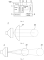
- the radio frequency identification system of the present application comprises a reader 100 and one or more electronic tags 200 located in the target area, and the electronic tags 200 can be passive tags, active tags or semi-active tags, the following takes the electronic tag 200 as a passive tag as an example for illustration.
- the reader 100 comprises a laser unit 1, an antenna unit 2 and a processor 3.
- the laser unit 1 comprises a transmitter 11 and a receiver 12.
- the transmitter 11 can emit an aiming light spot 13 to guide the user to aim at the target electronic tag 201 in the target area.
- the aiming light spot 13 is circular or cross-shaped.
- the aiming light spot 13 can also be an aiming frame, and the aiming frame can aim at one electronic tag 200 or at the same time a plurality of electronic tags 200.
- the aiming light spot 13 may be a combination of various shapes, for example, the center of the aiming frame has a circular or cross-shaped aiming light spot 13.
- Specific lenses can be configured for the laser unit 1 to form the aiming light spot 13 with a specific shape.
- the receiver 12 is used to receive the laser light reflected by the target area, so that the laser unit 1 also has a distance measuring function for measuring the distance between the target electronic tag 201 and the reader 100.
- the laser unit 1 measures the distance between the target electronic tag 201 in the target area and the reader 100 through infrared laser ranging, and at the same time, the infrared laser is doped with visible red light, and the aiming light spot 13 formed by the red light can guide the user to aim at the target electronic tag 201, so that the laser unit 1 realizes the functions of ranging and aiming at the same time.
- the laser unit 1 can perform ranging based on ranging principles such as time-of-flight ranging, phase ranging, or triangular ranging, and at the same time, the laser emitted by the laser unit 1 contains visible light, which can be used for aiming. It is conceivable that the aiming light spot 13 may not be easy to precisely aim at the target electronic tag 201, but slightly deviates from the target electronic tag 201. However, the distance between the aiming light spot 13 and other electronic tags 200 is greater than the distance d from the target electronic tag 201, and this error will also be considered later.
- ranging principles such as time-of-flight ranging, phase ranging, or triangular ranging
- the antenna unit 2 comprises a narrow-beam antenna, and the narrow-beam antenna may include a lens antenna, a parabolic antenna, a helical antenna, or a combination thereof.
- the lens antenna shown in FIG. 4 as an example, after the electromagnetic beam emitted by the antenna passes through the lens 21, the beam is narrowed, the energy is concentrated, and the directionality is better.
- the narrow-beam antenna can also be an array antenna as shown in FIG. 5 , and the array antenna can limit the angle of the beam 22 of the antenna unit 2 through beam-forming technology, so that the phased-array antenna emits narrow-beam electromagnetic waves.
- the angle of the wave lobe 22 of the antenna unit 2 can be controlled and adjusted, that is, when the target area is close, the user can expand the angle of the wave lobe 22 of the antenna unit 2, so that the user does not need to aim precisely, the reader 100 can read the target electronic tag 201.
- the user only needs to aim the aiming light spot 13 at the edge of the target electronic tag 201 or a certain area around it, and the antenna unit 2 can receive the radio frequency signal of the target electronic tag 201.
- the target electronic tag 201 is screened and read according to the matching degree between the distance measured by the laser unit 1 and the phase values of the radio frequency signals received by the antenna unit 2.
- the user can reduce the angle of the lobes 22 of the antenna unit 2 when the target area is far away, so that the lobes 22 of the antenna unit 2 cover a sufficiently small range on the target area. That is, the reading range of the antenna unit 2 surrounds the small area around the aiming light spot 13, so that the antenna unit 2 only receives the radio frequency signal emitted by the electronic tag 200 aimed at the aiming light spot 13, and is not affected by other electronic tags 200 around the electronic tag 200. At the same time, narrowing the angle of the wave lobe 22 of the antenna unit 2 can make the energy of the electromagnetic wave emitted by the antenna unit 2 more concentrated, and the reader 100 can excite or read the electronic tag 200 at a longer distance.
- a gear switch 4 can be set on the reader 100 to adjust the angle of the wave lobe 22 of the antenna unit 2, and the gear switch 4 can be a mechanical switch or a virtual touch switch set on the display screen 5 of the reader 100.
- the angle of the lobe 22 of the antenna unit 2 can be adjusted according to the distribution density of the electronic tags 200 in the target area. That is, when the distribution density of the electronic tags 200 in the target area is low, the angle of the wave lobe 22 of the antenna unit 2 is expanded, and when the distribution density of the electronic tags 200 in the target area is large, the angle of the wave lobe 22 of the antenna unit 2 is reduced. This is also to improve the reading efficiency and at the same time ensure that the antenna unit 2 only receives the radio frequency signal emitted from the electronic tag 200 targeted by the aiming light spot 13, without being affected by other electronic tags 200 around the electronic tag 200.
- the lobe center of the antenna unit 2 coincides with the aiming light spot 13, which can be realized through structural design.
- the antenna unit 2 is arranged coaxially with the laser unit 1; or the antenna unit 2 is adjacent to the laser unit 1, so that the lobe center of the antenna unit 2 is almost coincident with the aiming light spot 13, and the distance between the two is very close, so that in actual use, it can be considered that the lobe center coincides with the aiming light spot 13.
- the angle of the wave lobe 22 of the antenna unit 2 is adjusted in advance, so that the wave lobe 22 of the antenna unit 2 only covers a small area around the aiming light spot 13 in the target area.
- the wave lobe 22 of the antenna unit 2 only covers the target electronic tag 201 and does not cover other nearby electronic tags 200. This is an ideal situation, and the actual situation needs to consider factors such as the distance of the target area and the distribution density of the electronic tags 200.
- the working process of the radio frequency identification system of the present application is explained below through specific examples.
- the situation that only one electronic tag 200 is set in the target area is relatively simple.
- the reader 100 can read the electronic tag 200 without being interfered by other electronic tags 200 only by aiming at the electronic tag 200 by emitting an aiming pattern through the reader 100.
- the electronic tag 200 encodes the information of the corresponding item, and the user triggers the laser unit 1 to emit the aiming light spot 13 to aim at the target electronic tag 201 in the target area, and simultaneously measure the target electronic tag 201 and the target electronic tag 201.
- the antenna unit 2 emits electromagnetic waves to excite the electronic tag 200 aiming at the spot 13, and then receives the radio frequency signal emitted by the electronic tag 200 aiming at the spot 13.
- the processor 3 directly decodes the radio frequency signal, and the reader 100 reads the electronic tag 200 to obtain item information.
- the wave lobe 22 of the antenna unit 2 covers a plurality of electronic tags 200 on the target area at the same time, and the situation shown in FIG. 6 does not consider the reflection of electromagnetic waves. That is, the radio frequency signals emitted by other electronic tags 200 next to the electronic tag 200 targeted by the aiming light spot 13 will also be received by the antenna unit 2 after reflection. In both cases, it is necessary to further exclude the radio frequency signals emitted by other electronic tags 200 to distinguish the radio frequency signal emitted by the target electronic tag 201 aimed at by the aiming light spot 13.
- the processor 3 excludes radio frequency signals emitted by other electronic tags 200 according to the matching degree of the distance of the electronic tag 200 measured by the laser unit 1 and the phase values of the radio frequency signals received by the antenna unit 2, and distinguishes the radio frequency signal emitted by the electronic tag 200 aiming at the aiming light spot 13.
- the distance of the target electronic tag 201 is measured.
- the distance can be measured by the laser unit 1 or by other distance sensors 7.
- the laser unit 1 emits an aiming light spot 13 to aim at the target electronic tag 201 in the target area.
- the distance measured by the laser unit 1 to the target electronic tag 201 aimed at by the aiming light spot 13 is d.
- the intersection line between the spherical surface and the target area is the circle C1, and the distances from the points on the circle C1 to the laser unit 1 are all d. It can be seen that only the target electronic tag 201 is located on the circle C1, that is, the distance between the target electronic tag 201 and the laser unit 1 is d, while the distances between other electronic tags 200 and the laser unit 1 are not equal to d. Through this, the target electronic tag 201 can be identified. This is an ideal situation.
- the actual situation may be that, depending on the distance d of the target electronic tag 201 and the distribution density of the electronic tags 200 in the target area, there may be a plurality of electronic tags 200 located on the circle C1 at the same time. Therefore, the target electronic tag 201 needs to be screened out from the plurality of electronic tags 200 located on the circle C1. It can be seen from FIG. 7 that as long as there is only one electronic tag 200 at the intersection of the electronic tag 200 covered by the lobes 22 of the antenna unit 2 and the electronic tag 200 located on the circumference C1, then the only electronic tag 200 is the target electronic tag 201.
- the only electronic tag 200 is the target electronic tag 201.
- the aforementioned technique of adjusting the angle of the lobes 22 of the antenna unit 2 according to the distance and distribution density of the target electronic tags 201 can be used to screen the target electronic tags 201 here. That is, the angle of the lobe 22 of the antenna unit 2 is adjusted according to the actual situation, so that there is only one electronic tag 200 at the position where the lobe 22 of the antenna unit 2 intersects the circle C1.
- the reader 100 only needs to read one electronic tag 200 at a time, ideally, by using a narrow beam antenna or an array antenna, the lobes 22 of the antenna unit 2 are narrow enough to cover only one electronic tag 200. Therefore, there is no need to consider that there are a plurality of electronic tags 200 at the position where the lobe 22 of the antenna unit 2 intersects the circle C1.
- phase values of the radio frequency signals transmitted by the electronic tag 200 are obtained.
- the reader 100 transmits a radio frequency signal with frequency f (usually about 900 MHz) to the electronic tag 200:
- S tx Acos 2 ⁇ ft + ⁇
- A is the amplitude of the RF signal
- ⁇ is the initial phase of the transmitted RF signal.
- ⁇ is the gain of the RF signal sent back
- ⁇ is the modulation factor of the electronic tag 200
- ⁇ is the phase difference (phase value) generated by the RF signal during the entire propagation process.
- the reader 100 will acquire the phase value(phase difference) of the plurality of electronic tags 200: ⁇ 1 , ⁇ 2 , ⁇ 3 & ⁇ i .
- the distance measured by the laser unit 1 is matched with the phase value (phase difference) of the plurality of electronic tags 200 obtained by the reader 100 to determine the target electronic tag 201 among the plurality of electronic tags 200 .
- the specific process is as follows:
- [] is a rounding symbol, which means taking the integer part of (d/ ⁇ ).
- the threshold can be set for the difference or ratio between l i and x according to the distribution density of electronic tags 200. For example, when both
- the reader 100 can be configured such that the user triggers the laser unit 1 to emit the aiming light spot 13, and after a preset time, the laser unit 1 measures the distance of the target electronic tag 201 again, so that the user has enough time to adjust the position of the aiming light spot 13 and precisely aim at the electronic tag 200 in the target area.
- the antenna unit 2 receives the radio frequency signal emitted by the electronic tag 200 aiming at the light spot 13, so as to avoid that the reader 100 has already read other electronic tags 200 when the aiming light spot 13 has not aimed at the target electronic tag 201.
- the processor 3 decodes the target electronic tag 201 and displays the information of the electronic tag 200 on the display screen 5.
- the reader 100 can aim at the same time. This is because when the target area is far away, the resolution of the camera 6 can be higher than that of the human eye, and the user can roughly aim through the aiming light spot 13, and then observe the image collected by the camera 6 through the display screen 5. Precisely adjust the position of the aiming light spot 13 or the indicator 51, so that the image 13' or the indicator 51 of the aiming light spot on the display screen 5 overlaps with the image 201' of the target electronic tag, and accurately aim at the target electronic tag 201.
- the laser unit 1 only has an aiming function
- the reader 100 has another distance sensor 7 specially used for distance measurement, preferably with an accuracy of centimeter level or even millimeter level distance sensor 7, such as ultrasonic sensor, millimeter wave radar, etc.;
- the reader 100 guides the user to aim at the target area through the aiming light spot 13 emitted by the laser unit 1 , and the distance sensor 7 is configured to measure the distance between the position where the aiming light spot 13 is aiming at and the reader 100.
- the aiming function of the laser unit 1 can be replaced by other aiming units 8, that is, the aiming light spot 13 is formed by a combination of an ordinary LED lamp and a lens instead of a laser aiming light, to perform aiming.
- the reader 100 comprises a camera 6 and a display screen 5, through which images are collected by the camera 6, and images collected by the camera 6 are displayed through the display screen 5.
- the user adjusts the angle of the camera 6 to aim at the target area, and the position of the lobe center of the antenna unit 2 on the display screen 5 is indicated by the indicator 51 on the display screen 5. That is, the aiming function of the laser unit 1 is replaced by the cooperation of the camera 6 and the display screen 5, and the aiming pattern is replaced by the indicator 51.
- the reader 100 does not have a display screen 5, but uploads the information of the electronic tag 200 to a device with a display for display.
- FIG. 10 shows a radio frequency identification method, which is a flow chart of the reader 100 of the aforementioned embodiment reading the target electronic tag 201, wherein the reader 100 uses the laser unit 1 to perform aiming and ranging, and including the following steps:
- S10 Emit the aiming light spot 13 through the transmitter 11 to aim at the target electronic tag 201.
- S11 Receive the reflected light through the receiver 12 to measure the distance of the target electronic tag 201.
- S12 Receive a radio frequency signal transmitted by an electronic tag 200, when only a radio frequency signal of one electronic tag 200 is received, the electronic tag 200 is read; when the radio frequency signals of a plurality of electronic tags 200 are received, match phase values of the radio frequency signals of the plurality of electronic tags 200 with the distance d, and filter out the target electronic tag 201.
- FIG. 11 shows a radio frequency identification method, which is a flowchart of reading the target electronic tag 201 by the reader 100 of the aforementioned embodiment, including the following steps:
- the aiming light spot 13 can be emitted by the laser unit 1, or the aiming light spot 13 can be generated by a common LED lamp with a lens, or aimed by the camera 6 , or aimed by other mechanical structures.
- the distance may be measured by the laser unit 1 or by other distance sensors 7.
- S22 Receive a radio frequency signal transmitted by an electronic tag 200, when only a radio frequency signal of one electronic tag 200 is received, the electronic tag 200 is read; when the radio frequency signals of a plurality of electronic tags 200 are received, match phase values of the radio frequency signals of the plurality of electronic tags 200 with the distance d, and filter out the target electronic tag 201.
- FIG. 12 shows a radio frequency identification method, which is a flowchart of reading the target electronic tag 201 by the reader 100 of the aforementioned embodiment, including the following steps:
- S30 Collect the image of the target electronic tag 201 through the camera 6 and the display screen 5, so as to aim at the target electronic tag 201.
- the position of the lobe center of the antenna unit 2 on the display screen 5 is indicated by the indicator 51 on the display screen 5.
- the distance may be measured by the laser unit 1 or by other distance sensors 7.
- S32 Receive a radio frequency signal transmitted by an electronic tag 200, when only a radio frequency signal of one electronic tag 200 is received, the electronic tag 200 is read; when the radio frequency signals of a plurality of electronic tags 200 are received, match phase values of the radio frequency signals of the plurality of electronic tags 200 with the distance d, and filter out the target electronic tag 201.
Landscapes
- Engineering & Computer Science (AREA)
- Health & Medical Sciences (AREA)
- Toxicology (AREA)
- Physics & Mathematics (AREA)
- Electromagnetism (AREA)
- General Health & Medical Sciences (AREA)
- Artificial Intelligence (AREA)
- Computer Vision & Pattern Recognition (AREA)
- General Physics & Mathematics (AREA)
- Theoretical Computer Science (AREA)
- Computer Networks & Wireless Communication (AREA)
- Radar Systems Or Details Thereof (AREA)
Claims (14)
- Lesegerät (100), umfassend:eine Zieleinheit (1, 8), einen Abstandssensor (1, 7), eine Antenneneinheit (2) und einen Prozessor (3), wobei die Zieleinheit (1, 8) so konfiguriert ist, dass sie auf ein elektronisches Ziel-Etikett (201) zielt, der Abstandssensor (1, 7) so konfiguriert ist, dass er einen Abstand d zwischen dem elektronischen Ziel-Etikett (201) und dem Lesegerät (100) misst, und die Antenneneinheit (2) so konfiguriert ist, dass sie ein von dem elektronischen Ziel-Etikett (201) gesendetes Funkfrequenzsignal empfängt, wobei das Lesegerät (100) das elektronische Etikett (201) liest, wenn die Antenneneinheit (2) nur ein von einem elektronischen Etikett (201) gesendetes Funkfrequenzsignal empfängt;dadurch gekennzeichnet, dass, wenn die Antenneneinheit (2) Funkfrequenzsignale empfängt, die von einer Vielzahl elektronischer Etiketten (201) gesendet werden, der Prozessor (3) das elektronische Ziel-Etikett (201) aus der Vielzahl elektronischer Etiketten (201) gemäß einem Anpassungsgrad zwischen dem durch den Abstandssensor (1, 7) gemessenen Abstand d und den Phasenwerten der von der Antenneneinheit (2) empfangenen Funkfrequenzsignale herausfiltert.
- Lesegerät (100) nach Anspruch 1, wobei die Zieleinheit durch eine Lasereinheit (1) implementiert ist, die so konfiguriert ist, dass sie einen Ziellichtpunkt (13) emittiert, um auf das elektronische Ziel-Etikett (201) zu zielen, und der Abstandssensor durch die Lasereinheit implementiert ist, die so konfiguriert ist, dass sie den Abstand zwischen dem elektronischen Ziel-Etikett (201) und dem Lesegerät (100) misst;wobei, wenn die Antenneneinheit (2) die Funkfrequenzsignale der Vielzahl elektronischer Etiketten (200) gleichzeitig empfängt, der Abstand li, der den Phasenwerten der von der Vielzahl elektronischer Etiketten (201) übertragenen Funkfrequenzsignale entspricht, gemäß der folgenden Formel berechnet wird:
 eine Erinnerung an die von der Lasereinheit (1) gemessenen Abstand d und eine Wellenlänge λ des Funkfrequenzsignals ist:
 li mit x vergleichen, wenn eines von li gleich oder am nächsten zu x ist, ist das elektronische Etikett mit dem entsprechenden Phasenwert von Δϕi das elektronische Ziel-Etikett (201), oder, wenn |lm-x| und |ln-x| einen bestimmten Schwellenwert nicht überschreiten, sind die elektronischen Etiketten mit den Phasenwerten von Δϕm und Δϕn alle elektronische Ziel-Etiketten (201).
 - Lesegerät (100) nach Anspruch 2, wobei die Lasereinheit (1) einen Sender (11) und einen Empfänger (12) umfasst, der Sender (11) so konfiguriert ist, dass er den Ziellichtpunkt (13) projiziert, und der Empfänger (12) so konfiguriert ist, dass er ein reflektiertes Laserlicht empfängt, um den Abstand zwischen dem elektronischen Ziel-Etikett (201) und dem Lesegerät (100) zu messen.
- Lesegerät (100) nach Anspruch 1, wobei die Antenneneinheit (2) eine phasengesteuerte Gruppenantenne umfasst und ein Keulenwinkel der Antenne durch Strahlformung definiert ist, und das Lesegerät (100) mit einem Getriebeschalter (4) zum Einstellen des Keulenwinkels der Antenneneinheit (2) versehen ist.
- Lesegerät (100) nach Anspruch 4, wobei der Getriebeschalter (4) so konfiguriert ist, dass er den Keulenwinkel der Antenneneinheit (2) vergrößert, wenn der Abstand zwischen den elektronischen Ziel-Etiketten (201) gering ist, und so konfiguriert ist, dass er den Keulenwinkel der Antenneneinheit verringert, wenn der Abstand zwischen den elektronischen Ziel-Etiketten (201) groß ist.
- Lesegerät (100) nach Anspruch 4, wobei der Getriebeschalter (4) so konfiguriert ist, dass er den Keulenwinkel der Antenneneinheit (2) vergrößert, wenn die Dichte der elektronischen Etiketten um das elektronische Ziel-Etikett (201) niedrig ist, und so konfiguriert ist, dass er den Keulenwinkel der Antenneneinheit (2) verringert, wenn die Dichte der elektronischen Etiketten (201) um das elektronische Ziel-Etikett (201) hoch ist.
- Lesegerät (100) nach Anspruch 1, wobei der Ziellichtpunkt (13) mit einem Keulenmittelpunkt der Antenneneinheit zusammenfällt.
- Lesegerät (100) nach Anspruch 1, wobei die Zieleinheit (8) eine Kamera (6) und einen Anzeigebildschirm (5) umfasst, die Kamera (6) so konfiguriert ist, dass sie ein Bild des elektronischen Ziel-Etiketts (201) erfasst, der Anzeigebildschirm (5) so konfiguriert ist, dass er das Bild des elektronischen Ziel-Etiketts (201) anzeigt, und der Anzeigebildschirm (5) einen Indikator (51) zum Ausrichten auf das elektronische Ziel-Etikett (201) umfasst, und der Indikator (51) einen Keulenmittelpunkt der Antenneneinheit (2) markiert.
- Lesegerät (100) nach Anspruch 1, wobei die Antenneneinheit (2) eine Schmalstrahlantenne umfasst.
- Lesegerät (100) nach Anspruch 2, wobei der Ziellichtpunkt (13) auf einen Keulenmittelpunkt der Antenneneinheit (2) gerichtet ist.
- Funkfrequenz-Identifikationsverfahren, das umfasst:Ausrichten auf ein elektronisches Ziel-Etikett (201) durch eine Zieleinheit (8);Messen eines Abstands d zwischen dem elektronischen Ziel-Etikett (201) und einem Lesegerät (100) durch einen Abstandssensor (7);Empfangen eines von dem elektronischen Ziel-Etikett (201) gesendeten Funkfrequenzsignals durch eine Antenneneinheit (2), wenn nur ein von einem elektronischen Etikett (201) gesendetes Funkfrequenzsignal empfangen wird, Lesen des elektronischen Etiketts (201) durch das Lesegerät (100); dadurch gekennzeichnet, dass beim Empfang von Funkfrequenzsignalen, die von einer Vielzahl elektronischer Etiketten (201) gesendet werden, durch einen Prozessor (3) das elektronische Ziel-Etikett (201) aus der Vielzahl elektronischer Etiketten (201) entsprechend einem Anpassungsgrad zwischen dem von einem Abstandssensor (7) gemessenen Abstand d und Phasenwerten der von der Antenneneinheit (2) empfangenen Funkfrequenzsignale herausgefiltert wird.
- Funkfrequenz-Identifikationsverfahren nach Anspruch 11, wobei der Schritt des Ausrichtens durch Emittieren eines Ziellichtpunktes (13) zum Ausrichten auf das elektronische Ziel-Etikett (201) durch eine Lasereinheit (1) durchgeführt wird und der Schritt des Messens durch Messen des Abstands zwischen dem elektronischen Ziel-Etikett (201) und dem Lesegerät (100) durch die Lasereinheit (1) durchgeführt wird,wobei, wenn die Funkfrequenzsignale der Vielzahl elektronischer Etiketten (201) gleichzeitig empfangen werden, der Abstand li, der den Phasenwerten der von der Vielzahl elektronischer Etiketten (201) übertragenen Funkfrequenzsignale entspricht, gemäß der folgenden Formel berechnet wird:
 eine Erinnerung an die von der Lasereinheit gemessenen Abstand d und eine Wellenlänge λ des Funkfrequenzsignals ist:
 li mit x vergleichen, wenn eines von li gleich oder am nächsten zu x ist, ist das elektronische Etikett (201) mit dem entsprechenden Phasenwert von Δϕi das elektronische Ziel-Etikett (201), oder, wenn |lm-x| und |ln-x| einen bestimmten Schwellenwert nicht überschreiten, sind die elektronischen Etiketten (201) mit den Phasenwerten von Δϕm und Δϕn alle elektronische Ziel-Etiketten (201).
 - Funkfrequenz-Identifikationsverfahren nach Anspruch 12, wobei das Lesegerät (100) die Lasereinheit (1) umfasst und die Lasereinheit (1) so konfiguriert ist, dass sie den Ziellichtpunkt (13) aussendet, um auf das elektronische Ziel-Etikett (201) zu zielen und den Abstand zwischen dem elektronischen Ziel-Etikett (201) und dem Lesegerät (100) zu messen.
- Funkfrequenz-Identifikationsverfahren nach Anspruch 11, wobei das Lesegerät (100) eine Kamera (6) und einen Anzeigebildschirm (5) umfasst,
wobei das Ausrichten auf das elektronische Ziel-Etikett (201) umfasst:
Erfassen eines Bildes des elektronischen Ziel-Etiketts (201) durch die Kamera (6), Anzeigen des Bildes des elektronischen Ziel-Etiketts (201) durch den Anzeigebildschirm (5) und Ausrichten auf das elektronische Ziel-Etikett (201) durch einen Indikator (51) auf dem Anzeigebildschirm (5).
Applications Claiming Priority (1)
| Application Number | Priority Date | Filing Date | Title |
|---|---|---|---|
| PCT/CN2021/105046 WO2023279299A1 (zh) | 2021-07-07 | 2021-07-07 | 射频识别方法及阅读器 |
Publications (4)
| Publication Number | Publication Date |
|---|---|
| EP4167612A1 EP4167612A1 (de) | 2023-04-19 |
| EP4167612A4 EP4167612A4 (de) | 2024-05-15 |
| EP4167612B1 true EP4167612B1 (de) | 2025-02-12 |
| EP4167612C0 EP4167612C0 (de) | 2025-02-12 |
Family
ID=84800132
Family Applications (1)
| Application Number | Title | Priority Date | Filing Date |
|---|---|---|---|
| EP21948797.2A Active EP4167612B1 (de) | 2021-07-07 | 2021-07-07 | Hochfrequenzidentifikationsverfahren und lesegerät |
Country Status (3)
| Country | Link |
|---|---|
| US (1) | US12086677B2 (de) |
| EP (1) | EP4167612B1 (de) |
| WO (1) | WO2023279299A1 (de) |
Families Citing this family (2)
| Publication number | Priority date | Publication date | Assignee | Title |
|---|---|---|---|---|
| CN116106334B (zh) * | 2023-04-13 | 2023-06-09 | 中国民航大学 | 基于rfid的物品含水率无损检测方法 |
| WO2025141579A1 (en) * | 2023-12-28 | 2025-07-03 | Intact S.L Ltd. | A method and device for aiding correct pointing |
Family Cites Families (8)
| Publication number | Priority date | Publication date | Assignee | Title |
|---|---|---|---|---|
| US10757915B2 (en) | 2013-07-17 | 2020-09-01 | Donald Keith Lefevre | Long-range electronic identification system |
| US9872135B2 (en) * | 2014-12-31 | 2018-01-16 | Intermec Ip Corp. | Systems and methods for displaying location information for RFID tags |
| US10810387B2 (en) * | 2018-07-30 | 2020-10-20 | Hand Held Products, Inc. | Method, system and apparatus for locating RFID tags |
| US20210382164A1 (en) * | 2018-11-09 | 2021-12-09 | The Regents Of The University Of California | Multi-tone continuous wave detection and ranging |
| CN110647777A (zh) | 2019-09-18 | 2020-01-03 | 深圳盈达机器视觉技术有限公司 | 射频识别阅读器及其应用方法 |
| CN113553868A (zh) | 2021-06-23 | 2021-10-26 | 深圳盈达信息科技有限公司 | 射频识别方法及阅读器 |
| CN113553867A (zh) | 2021-06-23 | 2021-10-26 | 深圳盈达信息科技有限公司 | 射频识别方法及阅读器 |
| CN113553869A (zh) | 2021-06-23 | 2021-10-26 | 深圳盈达信息科技有限公司 | 射频识别方法及阅读器 |
-
2021
- 2021-07-07 US US18/089,153 patent/US12086677B2/en active Active
- 2021-07-07 WO PCT/CN2021/105046 patent/WO2023279299A1/zh not_active Ceased
- 2021-07-07 EP EP21948797.2A patent/EP4167612B1/de active Active
Also Published As
| Publication number | Publication date |
|---|---|
| US12086677B2 (en) | 2024-09-10 |
| EP4167612A1 (de) | 2023-04-19 |
| US20240273319A1 (en) | 2024-08-15 |
| WO2023279299A1 (zh) | 2023-01-12 |
| EP4167612C0 (de) | 2025-02-12 |
| EP4167612A4 (de) | 2024-05-15 |
Similar Documents
| Publication | Publication Date | Title |
|---|---|---|
| US8033465B2 (en) | Apparatus for searching RFID tag | |
| EP1751688B1 (de) | Indikatoren für die optimale positionierung einer datensammelvorrichtung zum lesen von datenträgern wie etwa rfid-etikette und maschinenlesbare symbole | |
| Keskilammi et al. | Radio frequency technology for automated manufacturing and logistics control. Part 1: Passive RFID systems and the effects of antenna parameters on operational distance | |
| US8167212B2 (en) | Radio frequency identification system and data reading method | |
| US7969281B2 (en) | Method and apparatus for identification of radio frequency tag | |
| EP2188868B1 (de) | Hochfrequenzsignalbeschaffungs- und quellenlokalisierungssystem | |
| US20110285593A1 (en) | Radio frequency positioning system for vehicles | |
| US20050212676A1 (en) | RFID tag reader with tag location indicated by visible light beam | |
| US12086677B2 (en) | Radio frequency identification method and reader | |
| US20200034583A1 (en) | Method, system and apparatus for locating rfid tags | |
| CN102301256A (zh) | 用于测定rfid应答器的距离、速度和/或运动方向的方法与系统 | |
| JPWO2019064989A1 (ja) | タグリーダー、rfidシステム、及び識別情報読み取り方法 | |
| WO2010035525A1 (ja) | 物品管理システム | |
| CN104199023A (zh) | 一种基于深度感知的rfid室内定位系统及其工作方法 | |
| CN113553869A (zh) | 射频识别方法及阅读器 | |
| JP4305420B2 (ja) | 質問器 | |
| JP2005345198A (ja) | 無線タグ通信システムの質問器及び無線タグ通信システム | |
| CN113553868A (zh) | 射频识别方法及阅读器 | |
| CN113553867A (zh) | 射频识别方法及阅读器 | |
| CN114841186A (zh) | 射频识别方法及阅读器 | |
| EP1946147B1 (de) | Entfernungsbestimmungssystem für kurze distanzen | |
| CN105929387A (zh) | 隧道里基于rfid功率发射档识别自适用测距方法 | |
| JP2021032847A (ja) | 車載用パッシブレーダ装置 | |
| CN112285690B (zh) | 毫米雷达波测距传感装置 | |
| CN223052366U (zh) | 一种天线定位装置 |
Legal Events
| Date | Code | Title | Description |
|---|---|---|---|
| STAA | Information on the status of an ep patent application or granted ep patent |
Free format text: STATUS: THE INTERNATIONAL PUBLICATION HAS BEEN MADE |
|
| PUAI | Public reference made under article 153(3) epc to a published international application that has entered the european phase |
Free format text: ORIGINAL CODE: 0009012 |
|
| STAA | Information on the status of an ep patent application or granted ep patent |
Free format text: STATUS: REQUEST FOR EXAMINATION WAS MADE |
|
| 17P | Request for examination filed |
Effective date: 20230116 |
|
| AK | Designated contracting states |
Kind code of ref document: A1 Designated state(s): AL AT BE BG CH CY CZ DE DK EE ES FI FR GB GR HR HU IE IS IT LI LT LU LV MC MK MT NL NO PL PT RO RS SE SI SK SM TR |
|
| A4 | Supplementary search report drawn up and despatched |
Effective date: 20240415 |
|
| RIC1 | Information provided on ipc code assigned before grant |
Ipc: G06K 7/10 20060101ALI20240409BHEP Ipc: H04W 4/80 20180101AFI20240409BHEP |
|
| DAV | Request for validation of the european patent (deleted) | ||
| DAX | Request for extension of the european patent (deleted) | ||
| GRAP | Despatch of communication of intention to grant a patent |
Free format text: ORIGINAL CODE: EPIDOSNIGR1 |
|
| STAA | Information on the status of an ep patent application or granted ep patent |
Free format text: STATUS: GRANT OF PATENT IS INTENDED |
|
| INTG | Intention to grant announced |
Effective date: 20241118 |
|
| GRAS | Grant fee paid |
Free format text: ORIGINAL CODE: EPIDOSNIGR3 |
|
| GRAA | (expected) grant |
Free format text: ORIGINAL CODE: 0009210 |
|
| STAA | Information on the status of an ep patent application or granted ep patent |
Free format text: STATUS: THE PATENT HAS BEEN GRANTED |
|
| AK | Designated contracting states |
Kind code of ref document: B1 Designated state(s): AL AT BE BG CH CY CZ DE DK EE ES FI FR GB GR HR HU IE IS IT LI LT LU LV MC MK MT NL NO PL PT RO RS SE SI SK SM TR |
|
| REG | Reference to a national code |
Ref country code: GB Ref legal event code: FG4D |
|
| REG | Reference to a national code |
Ref country code: CH Ref legal event code: EP |
|
| REG | Reference to a national code |
Ref country code: DE Ref legal event code: R096 Ref document number: 602021026215 Country of ref document: DE |
|
| REG | Reference to a national code |
Ref country code: IE Ref legal event code: FG4D |
|
| U01 | Request for unitary effect filed |
Effective date: 20250310 |
|
| U07 | Unitary effect registered |
Designated state(s): AT BE BG DE DK EE FI FR IT LT LU LV MT NL PT RO SE SI Effective date: 20250317 |
|
| PG25 | Lapsed in a contracting state [announced via postgrant information from national office to epo] |
Ref country code: RS Free format text: LAPSE BECAUSE OF FAILURE TO SUBMIT A TRANSLATION OF THE DESCRIPTION OR TO PAY THE FEE WITHIN THE PRESCRIBED TIME-LIMIT Effective date: 20250512 |
|
| PG25 | Lapsed in a contracting state [announced via postgrant information from national office to epo] |
Ref country code: PL Free format text: LAPSE BECAUSE OF FAILURE TO SUBMIT A TRANSLATION OF THE DESCRIPTION OR TO PAY THE FEE WITHIN THE PRESCRIBED TIME-LIMIT Effective date: 20250212 |
|
| PG25 | Lapsed in a contracting state [announced via postgrant information from national office to epo] |
Ref country code: ES Free format text: LAPSE BECAUSE OF FAILURE TO SUBMIT A TRANSLATION OF THE DESCRIPTION OR TO PAY THE FEE WITHIN THE PRESCRIBED TIME-LIMIT Effective date: 20250212 |
|
| PG25 | Lapsed in a contracting state [announced via postgrant information from national office to epo] |
Ref country code: IS Free format text: LAPSE BECAUSE OF FAILURE TO SUBMIT A TRANSLATION OF THE DESCRIPTION OR TO PAY THE FEE WITHIN THE PRESCRIBED TIME-LIMIT Effective date: 20250612 Ref country code: NO Free format text: LAPSE BECAUSE OF FAILURE TO SUBMIT A TRANSLATION OF THE DESCRIPTION OR TO PAY THE FEE WITHIN THE PRESCRIBED TIME-LIMIT Effective date: 20250512 |
|
| PG25 | Lapsed in a contracting state [announced via postgrant information from national office to epo] |
Ref country code: HR Free format text: LAPSE BECAUSE OF FAILURE TO SUBMIT A TRANSLATION OF THE DESCRIPTION OR TO PAY THE FEE WITHIN THE PRESCRIBED TIME-LIMIT Effective date: 20250212 |
|
| PG25 | Lapsed in a contracting state [announced via postgrant information from national office to epo] |
Ref country code: GR Free format text: LAPSE BECAUSE OF FAILURE TO SUBMIT A TRANSLATION OF THE DESCRIPTION OR TO PAY THE FEE WITHIN THE PRESCRIBED TIME-LIMIT Effective date: 20250513 |
|
| U20 | Renewal fee for the european patent with unitary effect paid |
Year of fee payment: 5 Effective date: 20250709 |
|
| PG25 | Lapsed in a contracting state [announced via postgrant information from national office to epo] |
Ref country code: SM Free format text: LAPSE BECAUSE OF FAILURE TO SUBMIT A TRANSLATION OF THE DESCRIPTION OR TO PAY THE FEE WITHIN THE PRESCRIBED TIME-LIMIT Effective date: 20250212 |
|
| PG25 | Lapsed in a contracting state [announced via postgrant information from national office to epo] |
Ref country code: CZ Free format text: LAPSE BECAUSE OF FAILURE TO SUBMIT A TRANSLATION OF THE DESCRIPTION OR TO PAY THE FEE WITHIN THE PRESCRIBED TIME-LIMIT Effective date: 20250212 |
|
| PG25 | Lapsed in a contracting state [announced via postgrant information from national office to epo] |
Ref country code: SK Free format text: LAPSE BECAUSE OF FAILURE TO SUBMIT A TRANSLATION OF THE DESCRIPTION OR TO PAY THE FEE WITHIN THE PRESCRIBED TIME-LIMIT Effective date: 20250212 |
|
| PLBE | No opposition filed within time limit |
Free format text: ORIGINAL CODE: 0009261 |
|
| STAA | Information on the status of an ep patent application or granted ep patent |
Free format text: STATUS: NO OPPOSITION FILED WITHIN TIME LIMIT |
|
| REG | Reference to a national code |
Ref country code: CH Ref legal event code: L10 Free format text: ST27 STATUS EVENT CODE: U-0-0-L10-L00 (AS PROVIDED BY THE NATIONAL OFFICE) Effective date: 20251224 |
|
| 26N | No opposition filed |
Effective date: 20251113 |
|
| REG | Reference to a national code |
Ref country code: CH Ref legal event code: H13 Free format text: ST27 STATUS EVENT CODE: U-0-0-H10-H13 (AS PROVIDED BY THE NATIONAL OFFICE) Effective date: 20260224 |
|
| GBPC | Gb: european patent ceased through non-payment of renewal fee |
Effective date: 20250707 |
|
| PG25 | Lapsed in a contracting state [announced via postgrant information from national office to epo] |
Ref country code: GB Free format text: LAPSE BECAUSE OF NON-PAYMENT OF DUE FEES Effective date: 20250707 |
|
| PG25 | Lapsed in a contracting state [announced via postgrant information from national office to epo] |
Ref country code: CH Free format text: LAPSE BECAUSE OF NON-PAYMENT OF DUE FEES Effective date: 20250731 |