EP4167429A1 - Energy storage device, energy storage system comprising same and control method, pre-charging circuit for an energy storage device - Google Patents
Energy storage device, energy storage system comprising same and control method, pre-charging circuit for an energy storage device Download PDFInfo
- Publication number
- EP4167429A1 EP4167429A1 EP22201996.0A EP22201996A EP4167429A1 EP 4167429 A1 EP4167429 A1 EP 4167429A1 EP 22201996 A EP22201996 A EP 22201996A EP 4167429 A1 EP4167429 A1 EP 4167429A1
- Authority
- EP
- European Patent Office
- Prior art keywords
- node
- current
- energy storage
- switching unit
- unit
- Prior art date
- Legal status (The legal status is an assumption and is not a legal conclusion. Google has not performed a legal analysis and makes no representation as to the accuracy of the status listed.)
- Pending
Links
Images


Classifications
-
- H—ELECTRICITY
- H02—GENERATION; CONVERSION OR DISTRIBUTION OF ELECTRIC POWER
- H02J—CIRCUIT ARRANGEMENTS OR SYSTEMS FOR SUPPLYING OR DISTRIBUTING ELECTRIC POWER; SYSTEMS FOR STORING ELECTRIC ENERGY
- H02J7/00—Circuit arrangements for charging or depolarising batteries or for supplying loads from batteries
- H02J7/007—Regulation of charging or discharging current or voltage
-
- H—ELECTRICITY
- H02—GENERATION; CONVERSION OR DISTRIBUTION OF ELECTRIC POWER
- H02J—CIRCUIT ARRANGEMENTS OR SYSTEMS FOR SUPPLYING OR DISTRIBUTING ELECTRIC POWER; SYSTEMS FOR STORING ELECTRIC ENERGY
- H02J7/00—Circuit arrangements for charging or depolarising batteries or for supplying loads from batteries
- H02J7/0029—Circuit arrangements for charging or depolarising batteries or for supplying loads from batteries with safety or protection devices or circuits
- H02J7/00304—Overcurrent protection
-
- B—PERFORMING OPERATIONS; TRANSPORTING
- B60—VEHICLES IN GENERAL
- B60L—PROPULSION OF ELECTRICALLY-PROPELLED VEHICLES; SUPPLYING ELECTRIC POWER FOR AUXILIARY EQUIPMENT OF ELECTRICALLY-PROPELLED VEHICLES; ELECTRODYNAMIC BRAKE SYSTEMS FOR VEHICLES IN GENERAL; MAGNETIC SUSPENSION OR LEVITATION FOR VEHICLES; MONITORING OPERATING VARIABLES OF ELECTRICALLY-PROPELLED VEHICLES; ELECTRIC SAFETY DEVICES FOR ELECTRICALLY-PROPELLED VEHICLES
- B60L58/00—Methods or circuit arrangements for monitoring or controlling batteries or fuel cells, specially adapted for electric vehicles
- B60L58/10—Methods or circuit arrangements for monitoring or controlling batteries or fuel cells, specially adapted for electric vehicles for monitoring or controlling batteries
- B60L58/18—Methods or circuit arrangements for monitoring or controlling batteries or fuel cells, specially adapted for electric vehicles for monitoring or controlling batteries of two or more battery modules
-
- H—ELECTRICITY
- H01—ELECTRIC ELEMENTS
- H01M—PROCESSES OR MEANS, e.g. BATTERIES, FOR THE DIRECT CONVERSION OF CHEMICAL ENERGY INTO ELECTRICAL ENERGY
- H01M10/00—Secondary cells; Manufacture thereof
- H01M10/42—Methods or arrangements for servicing or maintenance of secondary cells or secondary half-cells
- H01M10/425—Structural combination with electronic components, e.g. electronic circuits integrated to the outside of the casing
-
- H—ELECTRICITY
- H01—ELECTRIC ELEMENTS
- H01M—PROCESSES OR MEANS, e.g. BATTERIES, FOR THE DIRECT CONVERSION OF CHEMICAL ENERGY INTO ELECTRICAL ENERGY
- H01M10/00—Secondary cells; Manufacture thereof
- H01M10/42—Methods or arrangements for servicing or maintenance of secondary cells or secondary half-cells
- H01M10/44—Methods for charging or discharging
- H01M10/441—Methods for charging or discharging for several batteries or cells simultaneously or sequentially
-
- H—ELECTRICITY
- H01—ELECTRIC ELEMENTS
- H01M—PROCESSES OR MEANS, e.g. BATTERIES, FOR THE DIRECT CONVERSION OF CHEMICAL ENERGY INTO ELECTRICAL ENERGY
- H01M50/00—Constructional details or processes of manufacture of the non-active parts of electrochemical cells other than fuel cells, e.g. hybrid cells
- H01M50/20—Mountings; Secondary casings or frames; Racks, modules or packs; Suspension devices; Shock absorbers; Transport or carrying devices; Holders
- H01M50/204—Racks, modules or packs for multiple batteries or multiple cells
-
- H—ELECTRICITY
- H01—ELECTRIC ELEMENTS
- H01M—PROCESSES OR MEANS, e.g. BATTERIES, FOR THE DIRECT CONVERSION OF CHEMICAL ENERGY INTO ELECTRICAL ENERGY
- H01M50/00—Constructional details or processes of manufacture of the non-active parts of electrochemical cells other than fuel cells, e.g. hybrid cells
- H01M50/20—Mountings; Secondary casings or frames; Racks, modules or packs; Suspension devices; Shock absorbers; Transport or carrying devices; Holders
- H01M50/296—Mountings; Secondary casings or frames; Racks, modules or packs; Suspension devices; Shock absorbers; Transport or carrying devices; Holders characterised by terminals of battery packs
-
- H—ELECTRICITY
- H01—ELECTRIC ELEMENTS
- H01M—PROCESSES OR MEANS, e.g. BATTERIES, FOR THE DIRECT CONVERSION OF CHEMICAL ENERGY INTO ELECTRICAL ENERGY
- H01M50/00—Constructional details or processes of manufacture of the non-active parts of electrochemical cells other than fuel cells, e.g. hybrid cells
- H01M50/50—Current conducting connections for cells or batteries
- H01M50/502—Interconnectors for connecting terminals of adjacent batteries; Interconnectors for connecting cells outside a battery casing
- H01M50/509—Interconnectors for connecting terminals of adjacent batteries; Interconnectors for connecting cells outside a battery casing characterised by the type of connection, e.g. mixed connections
- H01M50/512—Connection only in parallel
-
- H—ELECTRICITY
- H02—GENERATION; CONVERSION OR DISTRIBUTION OF ELECTRIC POWER
- H02J—CIRCUIT ARRANGEMENTS OR SYSTEMS FOR SUPPLYING OR DISTRIBUTING ELECTRIC POWER; SYSTEMS FOR STORING ELECTRIC ENERGY
- H02J7/00—Circuit arrangements for charging or depolarising batteries or for supplying loads from batteries
- H02J7/0013—Circuit arrangements for charging or depolarising batteries or for supplying loads from batteries acting upon several batteries simultaneously or sequentially
-
- H—ELECTRICITY
- H02—GENERATION; CONVERSION OR DISTRIBUTION OF ELECTRIC POWER
- H02J—CIRCUIT ARRANGEMENTS OR SYSTEMS FOR SUPPLYING OR DISTRIBUTING ELECTRIC POWER; SYSTEMS FOR STORING ELECTRIC ENERGY
- H02J7/00—Circuit arrangements for charging or depolarising batteries or for supplying loads from batteries
- H02J7/0029—Circuit arrangements for charging or depolarising batteries or for supplying loads from batteries with safety or protection devices or circuits
- H02J7/0031—Circuit arrangements for charging or depolarising batteries or for supplying loads from batteries with safety or protection devices or circuits using battery or load disconnect circuits
-
- B—PERFORMING OPERATIONS; TRANSPORTING
- B60—VEHICLES IN GENERAL
- B60L—PROPULSION OF ELECTRICALLY-PROPELLED VEHICLES; SUPPLYING ELECTRIC POWER FOR AUXILIARY EQUIPMENT OF ELECTRICALLY-PROPELLED VEHICLES; ELECTRODYNAMIC BRAKE SYSTEMS FOR VEHICLES IN GENERAL; MAGNETIC SUSPENSION OR LEVITATION FOR VEHICLES; MONITORING OPERATING VARIABLES OF ELECTRICALLY-PROPELLED VEHICLES; ELECTRIC SAFETY DEVICES FOR ELECTRICALLY-PROPELLED VEHICLES
- B60L2200/00—Type of vehicles
- B60L2200/32—Waterborne vessels
-
- B—PERFORMING OPERATIONS; TRANSPORTING
- B60—VEHICLES IN GENERAL
- B60L—PROPULSION OF ELECTRICALLY-PROPELLED VEHICLES; SUPPLYING ELECTRIC POWER FOR AUXILIARY EQUIPMENT OF ELECTRICALLY-PROPELLED VEHICLES; ELECTRODYNAMIC BRAKE SYSTEMS FOR VEHICLES IN GENERAL; MAGNETIC SUSPENSION OR LEVITATION FOR VEHICLES; MONITORING OPERATING VARIABLES OF ELECTRICALLY-PROPELLED VEHICLES; ELECTRIC SAFETY DEVICES FOR ELECTRICALLY-PROPELLED VEHICLES
- B60L58/00—Methods or circuit arrangements for monitoring or controlling batteries or fuel cells, specially adapted for electric vehicles
- B60L58/10—Methods or circuit arrangements for monitoring or controlling batteries or fuel cells, specially adapted for electric vehicles for monitoring or controlling batteries
- B60L58/12—Methods or circuit arrangements for monitoring or controlling batteries or fuel cells, specially adapted for electric vehicles for monitoring or controlling batteries responding to state of charge [SoC]
-
- H—ELECTRICITY
- H01—ELECTRIC ELEMENTS
- H01M—PROCESSES OR MEANS, e.g. BATTERIES, FOR THE DIRECT CONVERSION OF CHEMICAL ENERGY INTO ELECTRICAL ENERGY
- H01M2220/00—Batteries for particular applications
- H01M2220/20—Batteries in motive systems, e.g. vehicle, ship, plane
-
- H—ELECTRICITY
- H02—GENERATION; CONVERSION OR DISTRIBUTION OF ELECTRIC POWER
- H02J—CIRCUIT ARRANGEMENTS OR SYSTEMS FOR SUPPLYING OR DISTRIBUTING ELECTRIC POWER; SYSTEMS FOR STORING ELECTRIC ENERGY
- H02J2310/00—The network for supplying or distributing electric power characterised by its spatial reach or by the load
- H02J2310/40—The network being an on-board power network, i.e. within a vehicle
- H02J2310/42—The network being an on-board power network, i.e. within a vehicle for ships or vessels
Definitions
- the present disclosure relates to an energy storage device, in particular an electrical energy storage device, for a watercraft and an energy storage system for a watercraft with at least two such energy storage devices which are connected to one another in parallel.
- the disclosure further relates to control methods for the energy storage device and for the energy storage system and a pre-charge circuit for an energy storage device.
- Electrical energy storage devices such as batteries
- the load can be, for example, a propulsion electric motor of a watercraft such as a boat, a ship or a ferry.
- Batteries, in particular lithium-ion-based batteries usually have an integrated main switch for safety reasons, which can at least interrupt the current flowing out of the battery, in particular a discharge current.
- batteries can also be connected to one another initially or to switch on a battery bank which has a plurality of batteries, in order to form a switched-on battery bank.
- a battery When a battery is connected to a load that has a voltage source property, such as a capacitor, if the voltage levels of the battery and load are different, a large transient current flows when the main switch is closed, which can damage the main switch and other circuit components of the battery. It is therefore desirable to match or adapt the voltage levels of the battery and load prior to closing the main switch.
- a pre-charging circuit is usually used for this.
- Simple pre-charge circuits only include or consist of a switched resistor.
- the pre-charge current varies greatly as a function of the voltage at the terminals of the battery or the load voltage. It may increase depending on the capacity of the load very large power loss pulses in the resistor, which is why the design of the resistor for varying capacitance values is problematic. If the load has not only capacitive but also resistive components, it is often not possible to reach a voltage level at the load at which the main switch can be closed without problems due to the voltage division between the resistance of the pre-charging circuit and that of the load during pre-charging.
- External charging devices also called chargers, for batteries of this type typically have a so-called CCCV (“Constant Current, Constant Voltage”) charging characteristic or carry out a CCCV charging method.
- CCCV Constant Current, Constant Voltage
- a constant current phase charging takes place at a constant charging current that is limited by the external charging device.
- a constant voltage phase in which charging takes place at a constant voltage provided by the external charging device.
- the transition from the constant current phase to the constant voltage phase takes place when the battery voltage reaches a specified end-of-charge voltage.
- the battery voltage is monitored by the external charger.
- the charging current drops slowly and charging is terminated when the charging current has fallen below a threshold value.
- the external charging device is typically equipped with a negative tolerance.
- the external charging device already switches to the constant voltage phase when the battery voltage reaches a value that is below the actual end-of-charge voltage of the battery battery is lying.
- This tolerance varies between loaders.
- the batteries normally do not reach an SOC (short for "state of charge”) of 100%. This in turn makes it difficult to recalibrate the SOC measurement.
- the constant voltage phase can be significantly longer due to the increased lead resistance and a satisfactory SOC cannot be achieved within an acceptable charging time.
- the present invention is based on the idea of providing a pre-charging circuit for an energy storage device, for example a battery, with an energy storage unit, for example at least one battery module.
- the energy storage device can thus be set up to limit the current strength of a discharge current for the energy storage unit to a predefined discharge current threshold value by means of the pre-charging circuit.
- the pre-charging circuit can thus have the character of a (constant) current source in this respect. As a result, a compensating current between energy storage devices connected to one another in parallel is possible, which is largely independent of the state of charge of the batteries.
- the pre-charging circuit is preferably designed as a regulated, clocked (constant) current source, which means that ohmic losses can be minimized.
- the energy storage device can be set up not to limit the current intensity of a charging current, i.e. a current in the opposite direction to the discharging current, for the energy storage unit, or the energy storage device has a significantly higher charging current threshold value, also known as current limit, for the current intensity of the charging current than for the discharge current.
- the pre-charging circuit thus has the character of a (constant) voltage source in this respect.
- the energy storage unit with the higher state of charge and thus with the higher voltage can be limited in the discharge current when balancing the energy contents, while the energy storage unit with the lower State of charge and thus with the lower voltage in the charging current is not limited.
- the pre-charge circuit can also be referred to as an equalization circuit. Accordingly, the precharge (control) methods disclosed herein may be referred to as balancing (control) methods.
- the pre-charging circuit according to the invention also takes account of the fact that the main application of the energy storage unit is to supply an associated electrical load which is not itself an energy storage unit. Furthermore, the pre-charging circuit according to the invention is set up to, depending on the direction of the current flowing from or to the energy storage unit and/or the ratio of the voltage at the Energy storage unit used to change the voltage at the external terminals of the energy storage device from a current source to a voltage source or vice versa.
- the pre-charging circuit can use the situation have the right character. For example, if the respective energy storage unit has a higher voltage than the other energy storage units in the energy storage system, the current source character can take effect, and if the energy storage unit has a lower voltage, the voltage source character or the character of a current source with a significantly higher current limit can take effect.
- an energy storage device for a watercraft comprising: a first connection, also referred to as a terminal, and a second connection, and an energy storage unit having a first pole and a second pole, the first pole having the first terminal and the second pole is connected to the second terminal.
- the energy storage device further includes a pre-charge circuit and a controller.
- the control unit is set up to control the pre-charging circuit in order to limit the magnitude of a discharge current for the energy storage unit to a predefined discharge current threshold value.
- Limiting to the discharge current threshold here means that the magnitude of the discharge current is or remains equal to or less than the discharge current threshold or does not exceed the discharge current threshold.
- the control unit can be set up to control the precharging circuit in such a way that a maximum value of the current intensity of the discharge current or a time average value of the current intensity is equal to or less than the predefined discharge current threshold value or does not exceed the discharge current threshold value.
- the energy storage device may further be configured not to limit the magnitude of a charging current for the energy storage unit or to limit the magnitude of the charging current to a charging current threshold that is greater than the discharging current threshold.
- an energy storage device for a watercraft comprising: a first connection and a second connection, an energy storage unit with a first pole and a second pole, a first connecting line between the first pole and the first terminal, and a second connecting line between the second pole and the second terminal.
- the first pole is therefore connected to the first connection by means of the first connecting line and the second pole is connected to the second connection by means of the second connecting line.
- the first connection line has a first node connected to the first pole and a second node connected to the first port.
- the second connecting line has a fourth node connected to the second pole and the second port.
- the energy storage device further comprises a first switching unit, which is arranged in the first connection line between the first node and the second node and which is configured to switch a current from the first node to the second node.
- the first switching unit can also be referred to as the first main switch.
- the energy storage device further includes a pre-charge circuit.
- the pre-charge circuit includes a third connection line between the first node and the second node having a third node and an inductor between the third node and the second node, a fourth connection line between the third node and the fourth node, and a free wheeling diode connected in the fourth Connecting line is arranged and is arranged for a current from the fourth node to the third node in the forward direction.
- the third connection line comprises a first end which is connected or can be connected to the first node and a second end which is connected or can be connected to the second node.
- the third node is thus arranged between the first end and the second end of the third connecting line and the inductor is arranged between the third node and the second end of the third connecting line.
- the fourth connection line thus comprises a first end which is connected to the third node and a second end which is connected or can be connected to fourth nodes.
- the freewheeling diode is therefore arranged in the fourth connecting line between the first end and the second end of the fourth connecting line and arranged for a current from the third node or from the first end to the second end of the fourth connecting line in the reverse direction.
- the pre-charging circuit comprises a third switching unit which is arranged in the third connection line between the first node or the first end of the third connection line and the third node and for switching a current from first node or from the first end of the third connecting line to the third node.
- the energy storage device further includes a control unit for controlling the pre-charging circuit.
- control includes both control (open loop) and rules (closed loop).
- the control unit may be configured to control the pre-charging circuit to limit the magnitude of a discharge current for the energy storage unit to the predetermined discharge current threshold.
- the control unit can be set up to switch the first switching unit and/or the third switching unit in order to limit the intensity of the discharge current for the energy storage unit to the predefined discharge current threshold value.
- This pre-charging circuit thus advantageously enables a current limitation for discharge currents of the energy storage unit, that is to say currents which flow out of the energy storage unit.
- the pre-charge circuit does not include an ohmic resistor. Therefore, the pre-charge circuit is low-loss.
- the precharging circuit can relieve the load on the main switch when connecting a plurality of energy storage devices in parallel, in particular with the same nominal voltage of the energy storage units, and when connecting to a consumer or load, in particular to a capacitive and/or resistive load.
- an energy storage system for a watercraft comprising N energy storage devices according to embodiments of the present disclosure, the N energy storage devices being connected to one another in parallel by means of the first and second connections.
- N is a natural number equal to or greater than 2.
- an "(electrical) connection" between two elements means that there is a connection between them that is electrically conductive or current-carrying, ie it can between them an electric current flow.
- the electrical connection can be formed by a connecting line, or line for short, in between, it being possible for the connecting line to have at least one electrical or electronic component.
- directly connected means that a connecting line between the elements has no further electrical or electronic components.
- Switching an electrical connection or a current includes establishing an electrical connection such that a current flow is possible across it and separating/interrupting the electrical connection such that a current flow is interrupted or no current flow is possible or a current flow is prevented.
- the electrical connection can be separated, for example, by interrupting or separating the connecting line, for example by means of a switch or a transistor, so that the two ends of the connecting line are electrically insulated from one another.
- the current-carrying connection can be established by closing the connecting line so that current can (again) flow between the two ends.
- a current or flow of current between two elements or nodes includes a current in one direction between the two elements and a current in the other, opposite direction thereto.
- a current or flow of current from a first element to a second element denotes a current with positive current intensity from the first element to the second element.
- a value of a current or an amperage means the magnitude of the amperage.
- the discharging current denotes a current from or from the energy storage unit via the first pole for discharging the energy storage unit and the charging current denotes a current through the first pole to or into the energy storage unit for charging the energy storage unit.
- Charging the power storage device means charging the power storage unit thereof, and discharging the power storage device means discharging the power storage unit thereof.
- a connecting line can be implemented by an electrically conductive medium, for example a conductor track, a cable or a wire.
- the switching of a switching unit, a switch or a transistor comprises opening these elements so that the corresponding electrical connection or the connecting line is separated and closing these elements so that the electrical connection is established or the connecting line is closed. Opening can also be referred to as turning on or activating and closing can also be referred to as turning off or deactivating.
- battery or “battery system” or “battery bank” or similar terms are used in the present disclosure, adapted to the usual usage, for “accumulator” or “accumulator system” or “accumulator bank”. The same applies to corresponding terms.
- a voltage difference of the voltage of the first pole with respect to the voltage of the second pole of the energy storage device can be referred to as the voltage of the energy storage device or as the voltage across the energy storage device.
- a voltage difference between the voltage at the first connection and a voltage at the second connection can be used as the voltage of the terminals or as voltage at the terminals.
- a parallel connection of the energy storage devices in an energy storage system means that the energy storage devices are connected in parallel by means of the first and second connections. That is to say that the first and second connections of the respective energy storage devices are connected up in parallel.
- aspects of the present disclosure may include one or more of the following optional features.
- the energy storage device can be set up to be connected to at least one further energy storage device in a parallel circuit by means of the first connection and the second connection.
- the energy storage unit can be set up to store electrical energy.
- the energy storage unit can be any device for storing energy that can be charged with electrical energy and from which electrical energy can be drawn.
- the energy storage unit can be or include at least one battery cell.
- the energy storage unit can be or include at least one battery module with at least one battery cell.
- the at least one battery cell can preferably be a lithium-based battery cell, in particular a lithium-ion-based battery cell.
- the energy storage unit can also be or comprise a flywheel system or a capacitor, for example an electrolytic capacitor or a supercapacitor.
- the energy storage device includes a second switching unit.
- the control unit can be set up to switch the second switching unit.
- the second switching unit can also be referred to as the second main switch.
- the second switching unit can be arranged in the first connecting line between the first node and the first pole and can be configured to switch a current from the first node to the first pole.
- the second switching unit can be arranged in the second connecting line between the second pole and the fourth node and set up to switch a current from the second pole to the fourth node.
- the first switching unit may comprise a first switch between the first node and the second node and a first diode connected in parallel to the first switch, conducting a current through the first diode from the first node to the second node is arranged in the blocking direction.
- the first diode may be arranged for forward current from the second node to the first node.
- the first switch and the first diode are connected to the first node and the second node, respectively. Accordingly, the first diode can be arranged between the first node and the second node.
- the third switching unit may include a third switch between the first node and the third node and a third diode connected in parallel with the third switch and arranged for reverse current through the third diode from the first node to the third node.
- the third diode may be arranged for forward current from the third node to the first node.
- the third switch and the third diode are connected to the first node and the third node, respectively. Accordingly, the third diode can be arranged between the first node and the third node.
- the second switching unit may include a second switch between the first node and the first pole, and a second diode connected in parallel with the second switch and arranged to reverse current across the second diode from the first node to the first pole.
- the second diode may be arranged for a forward current from the first pole to the first node.
- the second switch and the second diode are connected to the first node and the first pole, respectively. Accordingly, the second diode can be arranged between the first node and the first pole.
- the energy storage device comprises a fourth switching unit, which is arranged in the fourth connecting line between the third node and the fourth node and is set up to switch a current from the third node to the fourth node.
- the fourth switching unit is arranged in the fourth connection line between the first end and the second end of the fourth connection line and configured to switch a current from the third node to the second end of the fourth connection line.
- the fourth switching unit can include the freewheeling diode.
- the switching unit comprises a fourth switch between the fourth node and the second node, the freewheeling diode being connected in parallel to the fourth switch.
- the fourth switch and the freewheeling diode are connected to the third node and the fourth node, respectively.
- the control unit can be set up to switch the fourth switching unit.
- Each of the switching units is configured to switch current in one direction.
- Each of the switching units can be arranged to pass or not to interrupt current in the other direction.
- the first switching unit is set up to power from the first switch node to the second node.
- the second switching unit is set up to switch current from the first node to the first pole.
- the third switching unit is set up to switch current from the first node to the third node.
- the fourth switching unit is configured to switch power from the third node to the fourth node.
- the first switching unit can be designed as a power switch, in particular as a power transistor, preferably as a MOSFET.
- the first diode may preferably be constituted by a parasitic diode thereof.
- the second switching unit can be designed as a power switch, in particular as a power transistor, preferably as a MOSFET.
- the second diode may preferably be constituted by a parasitic diode thereof.
- the third switching unit can also be designed as a power switch, in particular as a power transistor, preferably as a MOSFET.
- the third diode may preferably be constituted by a parasitic diode thereof.
- the fourth switching unit can particularly preferably be designed as a power switch, in particular as a power transistor, preferably as a MOSFET.
- the flyback diode may preferably be formed by a parasitic diode thereof.
- the respective circuit breaker can also be referred to as a power electronic switching element.
- the circuit breakers may be capable of blocking current in only one direction. As a result, the respective switching unit can be set up to switch current in this direction. Accordingly, the circuit breaker cannot be capable of blocking current in the opposite direction to this direction.
- One direction can be referred to as the forward direction.
- the other direction can be called reverse direction. Accordingly, the circuit breaker can be blockable in the forward direction and non-blockable in the reverse direction.
- a charging current for the energy storage unit can thus be switched by means of the second switching unit.
- the charging current can be interrupted by opening the second switching unit.
- a discharge current can be switched by means of the first switching unit and the third switching unit.
- the discharge current can be interrupted by opening the first and third switching units.
- the control unit may be set up to implement control methods for the energy storage device and/or the energy storage system according to embodiments of the present disclosure to perform.
- the control unit can be set up to carry out control methods according to embodiments of the present disclosure.
- the control unit can be in the form of a two-point controller, a hysteresis controller and/or a limiting controller, preferably a linear limiting controller.
- the control unit can preferably be set up to control or switch the first switching unit and/or the second switching unit and/or the third switching unit and/or the fourth switching unit.
- Controlling the switching units here means driving the switching units in order to switch the switching units, that is to say to open or switch them on or to close or switch them off.
- the control unit can be set up to repeatedly switch at least one of the first switching unit, the second switching unit, the third switching unit and the fourth switching unit.
- the control unit can also be set up to switch at least one of the switching units alternately, i.e. to open and close it alternately.
- the control unit can be set up to switch at least one of the switching units repeatedly and alternately, in particular based on a predefined switching frequency and/or based on a predefined duty cycle, also referred to as clocked or periodic switching.
- the control unit can be set up to switch at least one of the switching units based on or using a pulse width modulation method.
- a reciprocal of the switching frequency may indicate a sum of an opening duration of the corresponding switching unit and a closing duration of the switching unit.
- the opening duration of the corresponding switching unit can define a duration between opening and closing, ie the duration during which the switching unit is open.
- the closing time of the switching unit can define a time period between closing and opening, ie the time period during which the switching unit is closed.
- the duty cycle or duty cycle may define a ratio between the dwell time and the sum of the open time and the dwell time. In this case, a large pulse duty factor can correspond to a large pulse width of the pulse width modulation method and vice versa.
- the pulse width can correspond to the closing time.
- the duty cycle can also be referred to as "duty cycle".
- control unit can be set up to switch at least one of the switching units based on or using a two-point control method and/or a hysteresis control method and/or a linear control method.
- the control unit can be set up to switch at least one of the switching units based on a direction and/or strength of a current and/or based on a level of a voltage.
- control unit can be set up to switch at least one of the first switching unit, the second switching unit, the third switching unit and the fourth switching unit based on or as a function of at least one of the following: a level of the voltage at the energy storage unit, a level of the Voltage at the terminals, a ratio between these voltage levels, a direction and/or strength of a current via the first connecting line between the first terminal and the second node, a direction and/or strength of a current via the third connecting line between the third node and the second node, a direction and/or strength of a current via the first connection line between the first node and the first pole, a strength of the charging current for the energy storage unit, a strength of the discharging current for the energy storage unit.
- control unit can be set up to close the third switching unit in an optional first step.
- control unit can also close the second switch and .
- the closing of the second switch can take place at the same time, before or after the closing of the third switching unit.
- the control unit can also be set up to close the first switching unit in a second step, in particular if a current flows or is present from the first connection to the second node, or if a charging current is flowing or present.
- the presence of a current may be defined such that a magnitude of the current is greater than a lower threshold, for example 0A.
- the control unit can open the third switching unit, in particular immediately after closing the first switching unit.
- the charging current for the energy storage unit can flow essentially completely via the first switching unit in an advantageous manner.
- the first switching unit can have a higher current carrying capacity than the third switching unit.
- control unit can be set up to close the third switching unit in an optional first step.
- control unit can also close the second switching unit.
- the closing of the second switching unit can take place at the same time, before or after the closing of the third switching unit.
- the control unit can also be set up to open the third switching unit in a second step.
- the control unit can be set up to close the third switching unit in a third step.
- the control unit can carry out the second and the third step repeatedly and alternately.
- the control unit can repeatedly and alternately open and close the third switching unit.
- the control unit can be set up to repeatedly and alternately open and close the third switching unit in such a way that a mean value over time or a maximum value of the current intensity of the discharge current and/or a current from the third node to the second node is equal to or less than the discharge current threshold is.
- the control unit can be set up to repeatedly and alternately open and close the third switching unit based on a predetermined pre-charging switching frequency and/or based on a predetermined pre-charging duty cycle, i.e. to switch repeatedly and alternately.
- the control unit can carry out a pulse width modulation method for switching the third switching unit.
- the control unit can be set up to set and/or change the pre-charging switching frequency and/or the pre-charging duty cycle. For example, the control unit can be set up to change, in particular to reduce or increase, the pre-charging switching frequency and/or the pre-charging duty cycle continuously and/or in steps.
- the control unit can be set up to open the third switching unit in the second step if the amperage of the current from the third node to the second node or of the discharge current is greater than a predetermined first threshold value or exceeds this threshold value.
- the control unit can be set up to close the third switching unit in the third step if the current strength is equal to or less than a predetermined second threshold value or falls below this.
- the second threshold value can be equal to or smaller than the first threshold value.
- the control unit can carry out a two-point control method or a hysteresis control method.
- the first threshold value can be equal to or greater than the discharge current threshold value.
- the maximum value or the mean value over time of the current intensity of the discharge current or the current from the third node to the second node can be limited to the discharge current threshold value.
- the control unit can be set up to close the first switching unit.
- the control unit can be set up to carry out this step if the amperage of the current from the third node to the second node and/or the amperage of the discharge current is equal to or less than a predetermined third threshold value or falls below the third threshold value and/or if a difference between the level of the voltage at the energy storage unit and the level of the voltage at the terminals is equal to or smaller than a predetermined fourth threshold value or falls below the fourth threshold value.
- the difference may indicate the result of subtracting the magnitude of the voltage across the terminals from the magnitude of the voltage across the energy storage device.
- the control unit can be set up to then leave the first switching unit continuously closed, in particular not to open it any longer.
- the control unit can be set up to open the third switching unit after closing the first switching unit, in particular immediately afterwards.
- the control unit can be set up to leave the third switching unit continuously open, in particular no longer to close it.
- the fourth threshold may correspond to a maximum allowable voltage difference between the voltage across the energy storage unit and the voltage across the terminals.
- the control unit can be set up to control the pre-charging circuit in order to increase or maintain the voltage at the energy storage unit and/or to maintain the amperage of the charging current, in particular during a charging process of the energy storage unit or while a charging current for charging the energy storage unit is flowing.
- the control unit can be set up to switch the fourth switching unit in order to increase or maintain the voltage at the energy storage unit and/or to increase and maintain the current strength of the charging current.
- the control unit can be set up to close the second switching unit in an optional first step. In this first step, the control unit can also close the first switching unit.
- the control unit can be set up to open the first switching unit in an optional second step.
- the control unit can be set up to close the fourth switching unit in a third step.
- the control unit can be set up to open the fourth switching unit in a fourth step.
- the control unit can be set up to open the second switching unit in an optional fifth step.
- the control unit preferably opens the second switching unit when the SOC of the energy storage unit has reached more than 99%, in particular approximately or essentially 100%, and/or when the voltage U at the energy storage unit has reached a predetermined value.
- the third switching unit can be open or closed during the first to fifth steps.
- the third switching unit is preferably closed at least when the fourth switching unit is open.
- control unit can open the first switching unit according to the optional second step and switch the fourth switching unit according to the third and fourth steps and for the first time when the current from the first connection to the second node and/or when the charging current is equal to or less than a booster Threshold or falls below the booster threshold and / or when the voltage at the terminals and / or the voltage at the energy storage unit is greater than a predetermined charging voltage threshold.
- the control unit can be set up to carry out the third step and the fourth step alternately and/or repeatedly.
- the control unit can be set up to repeatedly and alternately open and close the fourth switching unit.
- the control unit can be set up to repeatedly and alternately open and close the fourth switching unit in such a way that a time average value or a minimum value of the current intensity of the charging current and/or a current via the first connecting line from the first connection and to the second node is the same or is greater than the booster threshold.
- control unit can be set up to repeatedly and alternately open and close the fourth switching unit based on a predetermined charging switching frequency and/or based on a predetermined charging duty cycle, i.e. to switch repeatedly and alternately.
- control unit can carry out a pulse width modulation method for switching the fourth switching unit.
- the control unit can be set up to set and/or change the charging switching frequency and/or the charging duty cycle.
- the control unit can be set up to change, in particular to reduce or increase, the charging switching frequency and/or the charging duty cycle continuously and/or in steps.
- the control unit can be set up to close the fourth switching unit in the third step if the amperage of the current from the first connection to the second node or the amperage of the charging current is less than a predetermined first charging threshold value or exceeds this threshold value.
- the control unit can be set up to open the fourth switching unit in the third step if the current intensity is equal to or greater than a predefined second charging threshold value or exceeds it.
- the second charging threshold value can be equal to or greater than the first charging threshold value.
- the control unit can carry out a two-point control method or a hysteresis control method.
- the first threshold value can be equal to or smaller than the booster threshold value. Accordingly, the minimum value or the mean value over time the current strength of the charging current or the current from the first terminal to the second node are maintained at the booster threshold.
- the pre-charge circuit can be used as a boost converter ("booster"). As a result, it can be ensured during a charging process of the energy storage unit by an external charging device that the energy storage unit is reliably charged up to an SOC of 100%.
- boost converter boost converter
- an external charging device can be used to charge the energy storage device with a negative tolerance with regard to the end-of-charge voltage of the energy storage unit, and communication between the energy storage device and the charging device is not required for this.
- the booster can be implemented easily, since the freewheeling diode can only be implemented by the parasitic diode of a fourth switching unit, in particular a power transistor such as a MOSFET, and the control unit must be set up to switch the fourth switching unit.
- a pre-charge control method for an energy storage device according to embodiments of the present disclosure is provided.
- the pre-charge control method includes an optional step of closing the third switching unit.
- the second switching unit can also be closed here.
- the precharge control method further includes a step of closing the first switching unit when a current flows from the first terminal to the second node or when a charging current flows, and an optional step of opening the third switching unit after closing the first switching unit, specifically immediately after Closing the first switching unit.
- the pre-charge control method comprises an optional step of closing the third switching unit.
- the second switching unit can also be closed here.
- the method further includes the step of opening the third switching unit and a step of closing the third switching unit.
- the step of opening the third switching unit and the step of closing the third switching unit may be performed repeatedly and/or alternately based on a predetermined pre-charge switching frequency and/or based on a predetermined pre-charge duty cycle. That is, the third switching unit can be switched repeatedly and alternately based on the predetermined switching frequency and/or based on the predetermined duty cycle. As a result, a pulse width modulation method can be carried out.
- the pre-charging switching frequency and/or the pre-charging duty cycle can be changed, in particular reduced or increased, continuously and/or in steps.
- the step of opening the third switching unit can be carried out if the amperage of a current from the third node to the second node or the discharge current for the energy storage unit is greater than a predetermined first threshold value or exceeds this first threshold value and/or the step of closing the third Switching unit can be carried out when the current intensity is equal to or less than a predetermined second threshold value or falls below the second threshold value.
- the second threshold value can be equal to or smaller than the first threshold value.
- a two-point control method or a hysteresis control method can be carried out.
- the first threshold value can be equal to or greater than the discharge current threshold value.
- a charging control method for an energy storage device includes an optional first step of closing the second switching unit. In this step, the first switching unit can also be closed.
- the method includes an optional second step of opening the first switching unit.
- the method includes a third step of closing the fourth switching unit and a fourth step of opening the fourth switching unit.
- the method includes an optional fifth step of opening the second switching unit.
- the third switching unit can be open or closed during the process. The third switching unit is preferably closed at least when the fourth switching unit is open.
- the third and fourth steps can be carried out alternately and/or repeatedly.
- the fourth switching unit can be opened and closed repeatedly and alternately, in particular based on a predefined charging switching frequency and/or based on a predefined charging duty cycle.
- a pulse width modulation method for switching the fourth switching unit can be carried out.
- the switching frequency and/or the pulse duty factor can be changed continuously and/or in steps, in particular reduced or increased.
- the third step for closing the fourth switching unit can also be carried out if the amperage of a current from the first connection to the second node or the charging current for the energy storage unit is less than a predetermined first charging threshold value or falls below this threshold value and/or the fourth opening of the fourth switching unit can be carried out when the current is equal to or greater than a predetermined second charging threshold or falls below the second threshold.
- the second charging threshold value can be equal to or greater than the first charging threshold value.
- a two-point control method or a hysteresis control method can be carried out.
- the first threshold value can be equal to or smaller than the booster threshold value.
- the second to fourth steps can be performed when the current from the first connection to the second node and/or the charging current for the energy storage unit is equal to or less than the predetermined booster threshold value or falls below the booster threshold value.
- a pre-charge control method for an energy storage system includes performing the pre-charge control method for at least one, preferably a plurality, of the energy storage devices according to embodiments of the present disclosure.
- the pre-charge control method can be carried out simultaneously for all energy storage devices of the energy storage system.
- a charging control method for an energy storage system includes performing the charge control method for at least one, preferably a plurality, of the energy storage devices according to embodiments of the present disclosure.
- the charging control method can be carried out simultaneously for all energy storage devices of the energy storage system.
- the watercraft may be or include a ship, boat, or ferry.
- the first pole of the energy storage unit can be a positive pole of the energy storage unit and the second pole of the energy storage unit can be a negative pole of the energy storage unit.
- the energy storage device according to embodiments of the present disclosure is generally suitable for applications where multiple energy storage devices are or will be connected together in an energy storage system.
- the energy storage device for electric vehicles, stationary storage, large-scale systems, etc. is suitable.
- the control unit can be set up to set and/or change the discharge current threshold value and/or the charging current threshold value.
- the discharge current threshold value and/or the charging current threshold value can thus be variable or adjustable.
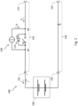
- FIG. 12 shows a schematic view of an energy storage device for a marine vehicle according to embodiments of the present disclosure.
- the energy storage device 100 comprises a first connection 111 and a second connection 112, and an energy storage unit 120 with a first pole 131 and a second pole 132, the first pole 131 being connected to the first connection 111 and the second pole 132 being connected to the second connection 112 is. More precisely, the first pole 132 is connected to the first connection 111 via a first connecting line 141 and the second pole 132 is connected to the second connection 112 via a second connecting line 142 .
- the energy storage unit 120 is set up to store electrical energy.
- the energy storage device 100 further comprises a first switching unit 171.
- the first switching unit 171 is arranged in the first connection line 141 between the first node K1 and the second node K2, i.e. it is connected to the first node K1 and the second node K2.
- the first switching unit 171 is configured to switch a current from the first node K1 to the second node K2.
- the first switching unit 171 can also be referred to as the first main switch.
- the energy storage device 100 is set up to be connected in an energy storage system 1000 for a watercraft (not shown) by means of the first connection 111 and the second connection 112 to at least one further energy storage device 100 ′ in a parallel circuit to become what's in figure 1 is illustrated by the first and second connections 111′, 112′ and connecting lines of the energy storage device 100′ shown in dashed lines.
- the energy storage system 1000 comprises two or more energy storage devices 100, 100' according to embodiments of the present disclosure, wherein the energy storage devices 100, 100 are connected to each other in parallel by means of the first and second terminals 111, 111', 112, 112'.
- the energy storage system 1000 is set up to supply electrical energy to an electrical load (not shown), for example an electric drive motor of the watercraft, using the electrical energy from the energy storage units 120 .
- the energy storage device 100 comprises a pre-charging circuit 150 and a control unit 160.
- the control unit 160 is configured to control the pre-charging circuit 150 in order to limit the strength of a discharge current I′ for the energy storage unit 120 to a predetermined discharge current threshold value.
- the pre-charging circuit 150 thus has the character of a (constant) current source in this respect.
- a compensating current between the energy storage devices 100, 100' connected to one another in parallel is possible, which is largely independent of the state of charge of the respective energy storage units 120. Accordingly, the pre-charge circuit 150 can be operated as a buck converter.
- the energy storage device 100 may further be configured not to limit the magnitude of a charging current I for the energy storage unit 120 or to limit the magnitude of the charging current I to a charging current threshold that is greater than the discharging current threshold.
- the charging current I is not limited or is limited to a threshold value which is greater than the threshold value for the discharging current I', the pre-charging circuit 150 can be used for a so-called asymmetric pre-charging of energy storage devices 100, 100' in an energy storage system 1000.
- the discharging current I' denotes a current from the energy storage unit 120 via the first pole 131, i.e. a current from the second pole 132 via the energy storage unit 120 to the first pole 131
- the charging current I denotes a current via the first pole 131 to the energy storage unit 120, i.e. a current from the first pole 131 via the energy storage unit 120 to the second pole 132.
- the energy storage unit 120 comprises according to in figure 1 embodiment shown one or more in figure 1 schematically indicated battery modules that are connected in series and / or in parallel.
- the battery module(s) each comprise one or more battery cells (not shown) connected in series and/or in parallel. Accordingly, the energy storage device 100 can be referred to as a battery and the energy storage system can be referred to as a battery system or battery bank.
- the battery cell or battery cells can be lithium-based, in particular lithium-ion-based.
- the battery module or modules are connected to the first and second poles 131, 132 of the energy storage unit 120 in order to provide or receive the electrical energy and a voltage U (see figure 3 ) between poles 131, 132.
- the poles 131, 132 have opposite polarity, the first pole 131 being the positive pole and the second pole 132 being the negative pole.
- the first pole 131 can form the cathode of the energy storage unit 120 and the second pole 132 can form the anode of the energy storage unit 120 in an idle state or during a discharging process of the energy storage unit 120 .
- the negative pole 132 may be connected to a ground of the energy storage device 100 and/or the energy storage system 100 .
- the voltage U can be positive.
- the voltage U can also be referred to as the voltage of the energy storage unit 120 .
- the energy storage unit 120 may be configured such that a value for a maximum possible charge current for the energy storage unit 120 is equal to or greater than (N-1) times the discharge current threshold. Also, the charging current threshold may be equal to or greater than (N-1) times the discharging current threshold.
- N represents the number of energy storage devices 100 connected in parallel in the energy storage system 1000. Thus, at N it is parallel switched, similar energy storage devices 100 in the energy storage system, it is possible for a single energy storage unit 120 to take up currents as charging current I, which the other N-1 energy storage units 120 can emit as respective discharge currents I' during the asymmetrical pre-charging, without the charging current I for this energy storage unit 120 has to be interrupted for safety reasons.
- the first connecting line 141 has a first node K1 connected to the first pole 131 and a second node K2 connected to the first terminal 111 .
- the second connection line 142 has a fourth node K4 which is connected to the second pole 132 and the second terminal 112 .
- the first terminal and the second terminal 111, 112 can be arranged on a housing (not shown) of the energy storage device 100 so that they are exposed to the outside and are therefore referred to as external terminals.
- FIG. 12 shows a schematic view of an energy storage device for a marine vehicle according to embodiments of the present disclosure. Based on figure 2 the current source character and the voltage source character of the precharge circuit are illustrated.
- the first switching unit 171 includes a first switch S1 and a first diode D1.
- the first switch S1 is connected to the first node K1 and the second node K2 and arranged to switch a current between the first node K1 and the second node K2 thereacross.
- the first diode D1 is connected to the first switch S1 in parallel, ie the first diode D1 is also connected to the first node K1 and the second node K2.
- the first diode D1 is reverse biased for current across from the first node K1 to the second node K2 and is forward biased for current across from the second node K2 to the first node K1. Accordingly, the anode of the first diode D1 is connected to the second node K2 and the cathode of the first diode D1 is connected to the first node K1.
- the first switching unit 171 is set up to switch, in particular to interrupt, a current from the first node K1 to the second node K2 via the first switching unit 171, but cannot be set up to switch a current from the second node K2 to the second node K2 due to the diode D1 to interrupt the first node K1 via the first switching unit 171.
- the first switching unit 171 can be implemented, for example, as a power switch, in particular as a power transistor, for example as a MOSFET, which is only for current in one direction (Forward direction) is capable of being blocked. For a current in the other direction, the opposite direction to this direction (reverse direction), the circuit breaker cannot be capable of blocking.
- the circuit breaker can also be described as reverse non-blocking.
- the circuit breaker can be blocking capable of flowing from the first node K1 to the second node K2 (forward direction) and therefore switch this current, and not capable of blocking a flow from the second node K2 to the first node K1 (reverse direction) and can therefore switch this current do not interrupt.
- the diode D1 is advantageously formed by the parasitic diode of the power transistor or MOSFET.
- a current I1 from the first connection 111 to the second node K2 and from the second node K2 via the first switching unit 171 and possibly via the pre-charging circuit 150 to the first node K1 can be essentially unlimited. From there, the current continues to flow to the first pole 131 and to the energy storage unit 120 as charging current I for charging the energy storage unit 120.
- This charging current I of the energy storage unit 120 is therefore not limited by the pre-charging circuit 50.
- a discharge current l' for discharging the energy storage unit 120 flows from the energy storage unit via the first pole 131 to the first node K1 and from there via the pre-charging circuit 150 as a current I2 to the second node K2 and to the first terminal 111.
- the pre-charging circuit 150 can use the current I2 and thus also limit the discharge current l'.
- the pre-charge circuit 150 acts as a current source in this regard.
- the discharge current I′ of the energy storage unit 120 can be limited by the pre-charging circuit 150 to a predefined discharge current limit value.
- the pre-charging circuit 150 can be designed as a regulated or clocked current source.
- the pre-charging circuit 150 therefore enables a current limitation for a discharge current I' of the energy storage unit 120 and/or no or a significantly higher current limitation for a charging current I of the energy storage unit 120.
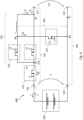
- FIG. 12 shows a schematic view of an energy storage device for a marine vehicle according to embodiments of the present disclosure.
- the energy storage device shown corresponds to that with reference to FIG figure 1 described energy storage device and shows further details thereof.
- the control unit 160 is in figure 3 Not shown.
- the pre-charge circuit 150 includes a third connection line 143 between the first node K1 and the second node K2, with a third node K3 and an inductor L between the third node K3 and the second node K2.
- the precharge circuit 150 further includes a fourth connection line 144 between the third node K3 and the fourth node K4, and a free wheeling diode D4 arranged in the fourth connection line 144 and arranged for a current I4 from the third node K3 to the fourth node K4 in the reverse direction and arranged for forward current from the fourth node K4 to the third node K3.
- the third connection line 143 comprises a first end that is connected or can be connected to the first node K1 and a second end that is connected or can be connected to the second node K2.
- the third node K3 is therefore arranged between the first end and the second end of the third connecting line 143 and the inductor L is arranged between the third node K3 and the second end of the third connecting line 143 .
- the fourth connecting line 144 thus comprises a first end which is connected to the third node K3 and a second end which is connected or can be connected to fourth node K4.
- the freewheeling diode D4 is therefore arranged in the fourth connecting line 144 between the first end and the second end of the fourth connecting line 144 and arranged for a current from the second end of the fourth connecting line 144 to the third node K3 or to the first end of the fourth connecting line 144 in the forward direction and is arranged for reverse flow from the third node K3 or from the first end of the fourth connection line 144 to the second end of the fourth connection line 144 .
- the pre-charging circuit 150 further comprises a third switching unit 173.
- the third switching unit 173 is arranged in the third connecting line 143 between the first node K1 or the first end of the third connecting line 143 and the third node K3, i.e. it is connected to the first node K1 and connected to the third node K3.
- the third switching unit 173 is set up to switch a current from the first node K1 or from the first end of the third connecting line 143 to the third node K3.
- the first switching unit 171 is therefore connected in parallel with the third connecting line 173 with the third switching unit 173 and the inductance L.
- the inductance L can be realized by a coil or the like.
- the energy storage device 100 also includes a second switching unit 172.
- the second switching unit 172 can also be referred to as a second main switch.
- the second switching unit 172 is arranged in the first connecting line 141 between the first node K1 and the first pole 131, ie it is connected to the first node K1 and the first pole 131.
- the second switching unit 172 for switching a current from the first node K1 to the first pole 131 set up.
- the arrangement of the second switching unit 172 is not on the arrangement of figure 2 limited.
- the second switching unit 172 can be arranged in the second connecting line 142 between the second pole 132 and the fourth node K4 and configured to switch a current from the second pole 132 to the fourth node K4.
- the control unit 160 which is figure 3 not shown, is set up to control the first switching unit 171 and the third switching unit 173, and can be set up in particular to switch the first switching unit 171 and the third switching unit 173 to increase the strength of the discharge current l' for the energy storage unit 120 via the first pole 131 and further to the first node K1 to a predetermined discharge current threshold value.
- the control unit 160 is also set up to switch the second switching unit 172 .
- the second switching unit 172 and the third switching unit 173 are constructed analogously to the first switching unit 171 .
- the second switching unit 172 includes a second switch S2 and a second diode D2.
- the second switch S2 is connected to the first node K1 and the first pole 131 and configured to switch a current between the first node K1 and the first pole 131 .
- the second diode D2 is connected to the second switch S2 in parallel, i.e. the second diode D2 is also connected to the first node K1 and the first pole 131.
- the second diode D2 is reverse biased for current across from the first node K1 to the first pole 131 and forward biased for current across from the first pole 131 to the first node K1.
- the second switching unit 172 is set up to switch a current I3 from the first node K1 to the first pole 131 .
- the third switching unit 173 includes a third switch S3 and a third diode D3.
- the third switch S3 is connected to the first node K1 and the third node K3 and configured to switch a current between the first node K1 and the third node K3.
- the third diode D3 is connected to the third switch S3 in parallel, ie the third diode D3 is also connected to the first node K1 and the third node K3.
- the third diode D3 is reverse biased for current across from the first node K1 to the third node K3 and is forward biased for current across the third node K3 to the first node K1 arranged.
- the third switching unit 173 is set up to switch a current from the first node K1 to the third node K3.
- the second switching unit 172 and the third switching unit 173 can be in the form of power switches, in particular in the form of a power transistor, preferably in the form of a MOSFET.
- the second diode D2 and the third diode D3 can preferably likewise be formed by the parasitic diode of the respective circuit breaker.
- the circuit breaker can be blockable for a current from the first node K1 to the first pole 131 (forward direction) and therefore switch this current, and the circuit breaker cannot for a current from the first pole 131 to the first node K1 (reverse direction). be blockable and therefore cannot interrupt this current.
- the circuit breaker can be blockable for a current from the first node K1 to the third node K3 (forward direction) and can therefore switch this current, and the circuit breaker cannot for a current from the third node K3 to the first node K1 (reverse direction). be blockable and therefore cannot interrupt this current.
- first to third switching units 171, 172, 173 are designed as power switches, in particular as MOSFETs, is in figure 4 illustrated.
- the control unit 160 can switch or control the charging current I from the first node K1 to the first pole 131 and to the energy storage unit 120 by means of the second switching unit 172 .
- control unit 160 can switch the second switching unit 172 in such a way, in particular by repeated and alternating opening and closing of the second switching unit 172, that a maximum value of the current intensity of the charging current I or a mean value over time of the current intensity is equal to or smaller than the specified charging current threshold value.
- the charging current I can be limited to the specified charging current threshold value.
- the discharge current I′ can also be interrupted by opening the first switching unit 171 and the third switching unit 173 .
- control unit 160 can switch or control the discharge current I′ from the energy storage unit 120 via the first pole 131 to the first node K1 by means of the first switching unit 171 and the third switching unit 173 .
- the discharge current I' can be limited to a predetermined discharge current threshold value.
- the energy storage device 100 can also include measuring devices for currents and voltages, which are not shown.
- the measuring devices can be set up to transmit the respectively measured currents or voltages to the control unit 160 .
- the control unit 160 can use the measured currents and voltages to perform control methods described below.
- Measuring a current may include determining whether a current is present in the corresponding direction, in particular whether a current magnitude thereof is greater than a predetermined lower threshold value, for example 0 A. Measuring the current may also include measuring an amperage. The measurement and transmission can be repeated and/or continuous.
- FIG. 12 shows a schematic view of a power storage device for a watercraft according to second embodiments of the present disclosure.
- the energy storage device 200 shown corresponds to that with reference to FIG figure 3 shown energy storage device 100 to the differences described below.
- the energy storage device 200 includes a fourth switching unit 174 arranged in the fourth connecting line 144 between the fourth node K4 and the third node K3. That is, the fourth switching unit 174 is connected to the fourth node K4 and the third node K3.
- the fourth switching unit 174 is arranged in the fourth connecting line 144 between the first end and the second end of the fourth connecting line 144 and is set up for switching a current from the third node K3 to the second end of the fourth connecting line 144.
- the fourth switching unit 174 is for switching a current set up from the third node K3 to the fourth node K4.
- the control unit 160 is also set up to switch the fourth switching unit 174 .
- the fourth switching unit 174 includes a fourth switch S4 and the freewheeling diode D4.
- the fourth switch S4 is connected to the third node K3 and the fourth node K4 and arranged to switch a current therebetween between the third node K3 and the fourth node K4.
- the freewheeling diode D4 is connected in parallel to the fourth switch S4, ie the freewheeling diode D4 is also connected to the third node K3 and the fourth node K4. Free wheeling diode D4 is reverse biased for current across from the third node K3 to the fourth node K4 and forward biased for current across from the fourth node K3 to the third node K3.
- the fourth switching unit 174 is configured to switch the current I4 from the third node K3 to the fourth node K4.
- the fourth switching unit 174 can be designed as a power switch, in particular as a power transistor, preferably as a MOSFET.
- the freewheeling diode D4 can be formed by the parasitic diode of the power switch. Accordingly, the circuit breaker can be blocking-capable for the current I4 from the third node K3 to the fourth node K4 (forward direction) and therefore switch this current, and the circuit-breaker can and cannot be blockable for a current from the fourth node K4 to the third node K3 (reverse direction). therefore do not interrupt this flow.
- the control unit 160 is configured to switch the first to fourth switching units 171, 172, 173, 174 to perform control methods for the energy storage device according to embodiments of the present disclosure.
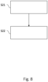
- figure 7 12 shows a precharge control method according to embodiments of the present disclosure.
- the precharge control method can be used for those referred to Figure 1 to Figure 6 shown energy storage devices are performed.
- the pre-charge control method can be performed simultaneously for a plurality of, preferably all, energy storage devices of an energy storage system connected in parallel according to embodiments of the present disclosure.
- the fourth switching unit 174 With reference to the in figure 5 and figure 6 shown embodiments of the energy storage device 200 should the fourth switching unit 174 here to be open.
- the pre-charging control method is preferably carried out when the energy storage system, which is embodied as a battery bank, for example, is switched on.
- control unit 160 closes the third switching unit 173 and the second switching unit 172 in a first step S11.
- control unit 160 can initially open the first switching unit 171 or leave it open.
- a discharge current l' flows from the energy storage unit 120 via the first pole 131 and further via the second switching unit 172, the first node K1, the closed third switching unit 173, the third node K3 and the second node K2 to the first port 111.
- I2 is substantially equal to l'.
- This discharge current I' can be used to charge the other energy storage units 120 with a lower state of charge.
- a current I1 flows from the first connection 111 to the node K2.
- the current is divided according to the impedances of the connecting lines or current paths between K2 and K1 via the third switching unit 173 or via the first switching unit 171.
- the current continues to flow from K1 to the first pole 131 and further as a charging current I for the energy storage unit 120.
- I1 is essentially equal to I.
- the charging current I of one energy storage unit 120 is also equal to the discharging current l 'of the other energy storage unit 120.
- control unit 160 then executes precharge control processes according to the embodiments described below in a step S12.
- figure 8 12 shows a precharge control method according to a first embodiment of the present disclosure.
- the precharge control method shown here can be used by the control unit in step S12 of figure 7 be performed.
- step S11 of FIG figure 7 determine whether a current I1 flows from the first terminal 111 to the second node K2, ie whether there is a current from the first terminal 111 to the second node K2.
- the control unit 160 determines whether the current intensity of the current I1 is greater than a predetermined lower threshold value, for example 0 A.
- the control unit 160 can determine whether a charging current I is present, or whether a current with the opposite direction to the current is present I2 is present. This is the case in particular when the energy storage unit 120 has a lower state of charge and therefore a lower voltage U in relation to the other energy storage units 120 in the energy storage system. In this case, the energy storage unit 120 is charged.
- control unit 160 closes first switching unit 171 in step S21. If first switching unit 171 and third switching unit 173 are MOSFETs, the current coming from node K2 commutes I1 largely via the first switching unit 171, i.e. on the first connecting line 141 between the second node K2 and the first node K1. This is due to the lower impedance of the MOSFET channel of the switched-on switching unit 171 in the first connection line 141 between the second node K2 and the first node K1 compared to that of the third connection line 143.
- control unit 160 can open the third switching unit 173 immediately after the closing of the first switching unit 171 .
- the energy stored in the inductance L can be dissipated via the third diode D3, which is formed by a MOSFET, for example.
- the energy storage unit 120 can be charged with a charging current I with a relatively large current intensity or with an unlimited charging current I through the pre-charging control method described here.
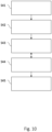
- figure 9 12 shows a pre-charge control method according to a second embodiment of the present disclosure.
- the pre-charge control method shown here can be executed by the control unit 160 in step S12 of FIG figure 7 be performed.
- control unit 160 opens third switching unit 173.
- control unit 160 closes third switching unit 173.
- step S11 of FIG figure 7 first determine whether a current I2 flows from the third node K3 to the second node K2, ie whether there is a current I2 from the third node K3 to the second node K2.
- the control unit 160 determines whether the current I2 is equal to or greater than a predetermined lower threshold value, for example 0 A.
- controller 160 may determine whether discharge current I' is present or whether a current of opposite direction to current I1 is present. This is the case in particular when the energy storage unit 120 has a higher state of charge and therefore a higher voltage U than the other energy storage units 120 in the energy storage system. In this case, the energy storage unit 120 is discharged.
- the control unit 160 may perform steps S31 and S32 when determining that a current I2 flows from the third node K3 to the second node K2.
- the third switching unit 173 By alternately opening and closing the third switching unit 173, it is possible to control the magnitude of the discharge current I'. For example, a maximum value or an average value over time of the current intensity can be controlled and, in particular, limited to the specified discharge current threshold value.
- control unit 160 is set up to repeatedly and alternately open and close the third switching unit 173, i.e. to repeatedly and alternately switch what is in figure 9 is illustrated by a double arrow between steps S31 and S32.
- the control unit 160 can limit the current strength of the discharge current I′ to the discharge current threshold value.
- the control unit 160 can in particular limit a mean value over time or a maximum value of the current strength of the discharge current I′ to the discharge current threshold value.
- the control unit can perform a pulse width modulation method for switching the third switching unit 173 alternately and repeatedly.
- an opening duration of the third switching unit 173 indicates a duration between opening and closing, ie the duration during which the third switching unit 173 is opened.
- a closing time of the third Switching unit 173 indicates a period of time between closing and opening, ie the period of time during which the third switching unit 173 is closed.
- a reciprocal of the sum of the opening duration and the closing duration can be defined as the switching frequency.
- a ratio between the dwell time and the sum of the open time and the dwell time may be defined as the duty cycle or duty cycle of the pulse width modulation scheme.
- a large duty cycle can correspond to a large pulse width and vice versa.
- a pulse width can correspond to the closing duration.
- the switching frequency and duty cycle are also referred to as precharge switching frequency and precharge duty cycle, respectively.
- the switching frequency, the closing duration, the opening duration and/or the pulse duty factor can be predetermined.
- these parameters can be specified or set by the control unit 160 and/or changed by the control unit 160 .
- the control unit 160 can be set up to change these parameters in stages and/or continuously.
- the control unit 160 can set the pulse duty factor in such a way that the mean value over time or maximum value of the current intensity of the discharge current I′ and/or the current I2 is limited to the discharge current threshold value.
- controller 160 may set the duty cycle or opening duration such that the average current I2 or discharge current I' is initially or limited to approximately 20 A, then is or is limited to approximately 15 A, and then approximately is or is limited to 10A. Accordingly, the pulse duty factor and/or the closing time is reduced in stages here.
- the switching frequency can be 100 kHz, for example.
- the control unit 160 can thus implement a linear limiting controller.
- control unit 160 opens the third switching unit 173 in step S31 if the current intensity of the discharge current I', the current I2 from the third node K3 to the second node K2 or the current in the opposite direction to the current I1 is greater than a predetermined first threshold value or exceeds this threshold.
- the current I2 through L then commutes via the fourth connecting line 144 and the freewheeling diode D4, whereupon the current I2 drops.
- the control unit 160 then closes the third switching unit 173 if the current strength is equal to or less than a predetermined second threshold value or this threshold value falls below As a result, the strength of the current I2 or the discharge current I' can rise again.
- the second threshold value can be equal to or smaller than the first threshold value.
- the control unit 160 can carry out a two-point control method or a hysteresis control method.
- the first threshold value can be equal to or greater than the discharge current threshold value.
- the maximum value or the mean value over time of the current strength of the discharge current I' or of the current I2 can be limited to the discharge current threshold value.
- control unit 160 closes the first switching unit 171 in a step S33 after step S32 if the current intensity of the current I2 from the third node K3 to the second node K2 and/or the discharge current I' is equal to or smaller than a predetermined third threshold value or falls below this threshold value and/or if a difference between the voltage U at the energy storage unit 120 and the voltage U1 at the terminals 111, 112 is equal to or smaller than a predetermined fourth threshold value or falls below this.
- the third threshold can be smaller than the first and/or second threshold.
- control unit 160 can open the third switching unit 173 immediately after the first switching unit 141 has closed.
- the control unit 160 can be set up to then leave the first switching unit 171 continuously closed, i.e. to no longer switch.
- the control unit 160 can leave the third switching unit 173 continuously open, i.e. no longer switching.
- the fourth threshold value can correspond to a maximum permissible voltage difference between the voltage U at the energy storage unit 120 and the voltage U1 at the terminals 111, 112.
- the first switching unit 171 as a main switch can be relieved by the precharge control method according to embodiments.
- the discharge current l' for the energy storage unit 120 via the precharging circuit 150 more precisely via the third connecting line 143 between the first node K1 and the third node K3, where it can be switched by the third switching unit 173.
- the strength of the discharge current I' can be limited to a predetermined discharge current threshold value.
- figure 10 12 shows a charging control method according to an embodiment of the present disclosure.
- the tax procedure can be related to figure 5 and figure 6 shown energy storage device are carried out.
- the charging control method can be used in particular for multiple or all energy storage devices connected in parallel of an energy storage system according to embodiments of the present disclosure may be performed simultaneously.
- the charging control method can also be referred to as a boost method or boost process.
- the charging control method shown here can be performed as part of or during a charging process for charging the energy storage unit 120 .
- the charging process can be carried out by an external charging device which is connected to the terminals 111, 112.
- the charging process can be a CCCV charging process.
- control unit 160 first closes the second switching unit 172 in an optional first step S41.
- the control unit 160 can also close the first switching unit 171 in this step.
- the closing of the first switching unit 171 can take place before, at the same time or after the closing of the second switching unit 172 .
- a current I1 provided by the external charging device can flow from the first connection 111 to the second node K2 and from there to the first pole 131 .
- the control unit 160 can also open the fourth switching unit 174 .
- a current I4 via the fourth connecting line 144 is thus initially prevented.
- control unit 160 can open the third switching unit 173 . If like with reference to figure 8 If the first and third switching units 171, 173 are designed as MOSFETs, due to the lower impedance of the MOSFET channel of the switched-on MOSFET 171, the current I1 coming from the node K2 largely commutes via the first switching unit 171, ie on the first connecting line 141 between the second Node K2 and the first node K1. However, the third switching unit 173 can also be closed.
- control unit 160 opens the first switching unit 171. This prevents a current flow via the first connecting line 141 from the first node K1 to the second node K2 in the subsequent steps.
- a third step S43 the control unit 160 closes the fourth switching unit 174. This enables a current I4 via the fourth connecting line 144 from the node K3 to the fourth node K4. This results in a current flow from the first connection 111 via the second node K2, the inductance L and the third node K3 and further via the fourth connecting line 144 to the fourth node K4. Thus, energy is stored in the inductance L in this phase.
- the control unit 160 then opens the fourth switching unit 174 in the fourth step S44.
- the current from the node K3 via the fourth connecting line 144 to the fourth node K4 thereby changes to the third connecting line 143 between the third node K3 and the first node K1.
- a current I3 flows further to the first pole 131 and further as a charging current I to the energy storage unit 120.
- the energy stored by the inductance L is thus released to the energy storage unit 120.
- the voltage U at the energy storage unit 120 is increased or maintained and the amperage of the charging current I for charging the energy storage unit 120 is increased or maintained.
- the switching unit 173 has the third switch S3 and the third diode D3, and if the switching unit 173 is designed in particular as a power switch, for example a MOSFET, the third diode D3 will take over the current from the node K3 after the opening of the fourth switching unit 174. In order to minimize losses, the control unit 160 can be set up to close the third switching unit 173 after the fourth switching unit 174 has opened.
- the control unit 160 can be set up to open the second switching unit 172 in an optional fifth step S45. As a result, the charging current I for the energy storage unit 120 is interrupted and the charging process can be ended. Control unit 160 preferably opens second switching unit 172 when the SOC of energy storage unit 120 has reached more than 99%, approximately or essentially 100% and/or when voltage U at energy storage unit 120 has reached a predetermined value. When the charging current I for the energy storage unit 120 is interrupted, it can be detected by the external charging device and the external charging device can stop charging.
- control unit 160 can open the first switching unit 171 according to step S42 and switch the fourth switching unit 174 according to steps S43 and S44 for the first time when the current I1 from the first connection 111 to the second node K2 and/or when the charging current I is equal to or smaller than a booster threshold value or falls below the booster threshold value and/or when the voltage U1 at the terminals 111, 112 and/or the voltage U at the energy storage unit 120 is greater than a predetermined charging voltage threshold value.
- the voltage U at the energy storage unit 120 can be maintained or increased by switching the fourth switching unit 174 . This also allows the amperage of the charging current I for the energy storage unit 120 maintained or increased. Accordingly, the pre-charging circuit 150 can be operated here as a step-up converter or boost converter.
- the boost converter can be easily implemented, since the freewheeling diode D4 can only be implemented by the parasitic diode of the fourth switching unit 174, in particular a power transistor such as a MOSFET, and the control unit 160 has to be set up to switch the fourth switching unit 174.
- the energy storage device 200 can thus carry out a kind of precision final charge of the energy storage unit 120 as required by the pre-charging circuit 150 .
- the targeted SOC of the energy storage unit 120 of 100% can be reliably achieved regardless of the type of installation.
- an external charging device can be used to charge the energy storage device 200 with negative tolerance.
- Negative tolerance means here that the external charging device changes from the constant voltage phase to the constant current phase when the voltage U1 at the terminals 111, 112 or a voltage U at the energy storage unit 120 reaches a value that is below the actual end-of-charge voltage of the Energy storage unit 120 is located. This value can also be referred to as the "internal end-of-charge voltage of the external charging device".
- an end-of-charge voltage of the energy storage unit 120 may be 30 V
- the internal end-of-charge voltage of the external charging device may be 29 V
- the charging voltage threshold at which the pre-charging circuit 150 starts switching the fourth switching unit 174 may be 28 V.
- a communication of the energy storage device 200 with the charging device is not necessary.
- External charging devices of any model and/or manufacturer that meet the charge shot voltage requirements of the energy storage unit 120 may be employed.
- the final final charge of the energy storage unit 120 can take place with higher power compared to charging with only the external charging device. This also simplifies connection in parallel configurations of battery banks.
- control unit 160 is set up in particular to carry out steps S43 and S44 alternately and/or repeatedly, which in figure 10 is illustrated by a double arrow between steps S43 and S44.
- the control unit 160 may be configured to repeat the fourth switching unit 174 according to the steps S43 and S44 and to close and open alternately, ie to switch repeatedly and alternately.
- the control unit 160 can be set up to repeatedly and alternately open and close the fourth switching unit 174 in such a way that a mean value over time or a minimum value of the current strength of the charging current I and/or the current I1 is transmitted via the first connecting line 141 from the first terminal 111 and to the second node K2 is equal to or greater than a booster threshold.
- the control unit 160 can in particular be set up to switch the fourth switching unit 174 repeatedly and alternately based on a predefined switching frequency and/or based on a predefined duty cycle, also referred to as clocked or periodic switching. As a result, the control unit 160 can carry out a pulse width modulation method for switching the fourth switching unit 174 .
- an opening duration of the fourth switching unit 174 indicates a duration between the opening and the closing, that is to say the duration during which the fourth switching unit 174 is open.
- a closing duration of fourth switching unit 174 indicates a duration between closing and opening, ie the duration during which fourth switching unit 174 is closed.
- a reciprocal of the sum of the opening duration and the closing duration can be defined as the switching frequency of the fourth switching unit 174 .
- a ratio between the dwell time and the sum of the open time and the dwell time may be defined as the duty cycle or duty cycle of the pulse width modulation scheme for the fourth switching unit 174 .
- a large pulse duty factor can correspond to a large pulse width and vice versa.
- a pulse width can correspond to the closing duration of the fourth switching unit 174 .
- the switching frequency can be approximately 100 kHz, for example.
- the switching frequency, the closing duration, the opening duration and/or the pulse duty factor can be predefined. In particular, these parameters can be specified or set by the control unit 160 and/or changed by the control unit 160 .
- the control unit 160 can be set up to change these parameters in stages and/or continuously. With reference to the in figure 10 described charging control method, the switching frequency and the duty cycle are also referred to as charging switching frequency and charging duty cycle.
- the control unit 160 can also carry out a two-point control method or a hysteresis control method.
- the control unit 160 can be set up to close the fourth switching unit 174 in the third step S43 if the amperage of the current I1 from the first connection 111 to the second node K2 or the charging current I is less than a predetermined first charging threshold value or exceeds this threshold value .
- the control unit 160 may be set up to open the fourth switching unit 174 in the fourth step S44 if the current strength is equal to or greater than one predetermined second charging threshold or exceeds it.
- the second charging threshold value can be equal to or greater than the first charging threshold value.
- the first threshold value can be equal to or smaller than a booster threshold value. Accordingly, the minimum value or the mean value over time of the current strength of the charging current I or of the current I1 can be maintained at the booster threshold value.
- the control unit 160 can be set up to reduce the booster threshold value, the closing duration and/or the duty cycle or the first charging threshold value and/or the second charging threshold value while the charging control method is being carried out or during the charging process.
- the effect of the voltage increase at the energy storage unit 120 can be gradually reduced or the minimum value or the mean value over time of the current intensity of the charging current I can be gradually reduced as a result.
- the booster effect of the charging control method or the pre-charging circuit 150 can be reduced as the SOC of the energy storage unit 120 increases.
- the value of a maximum current that the third switching unit 173 can carry and switch at maximum can be referred to as the current-carrying capacity of the third switching unit 173 .
- the current carrying capacity of the third switching unit 173 can correspond to approximately one tenth of the current carrying capacity of the first switching unit 171 and/or the second switching unit 172. According to embodiments, the current carrying capacity of the third switching unit 173 can correspond to the booster threshold value and/or the discharge current threshold value.
- the control units of the respective energy storage devices can communicate with each other.
- the pre-charge control method according to embodiments of the present disclosure is being performed for at least one of the energy storage devices, it can thereby be ensured that the charge control method is not performed for the other energy storage devices.
- this can prevent one or more energy storage devices from being discharged while the boost process is being carried out for the other energy storage devices at the same time.
- the pre-charging circuit according to embodiments of the present invention can therefore be used as a DC/DC converter, ie both as a buck converter and as a boost converter, and enables current limitation for discharge currents the energy storage unit or currents from the Energy storage device ("forward"), in particular for pre-charging. Balancing between energy storage devices connected in parallel can be performed for as long as necessary.
- the precharging circuit can limit a discharge current to 6A and/or an output power of 250W, in particular for loads without their own limiting circuit (so-called “dumb loads”). Short circuits can also be detected with the pre-charging circuit.
- the pre-charging circuit makes it possible to provide a 12V output ("forward") (see figure 1 ) to charge 12V board systems of a watercraft, for example.
- the 12V output can also be used as an input for currents (“backward”), for example for solar charging or for emergency applications.
- the pre-charge circuit also acts as a DC/DC converter, enabling voltage stabilization in the event of sudden internal switch-off conditions, for example an emergency stop signal.
Landscapes
- Engineering & Computer Science (AREA)
- Chemical & Material Sciences (AREA)
- General Chemical & Material Sciences (AREA)
- Electrochemistry (AREA)
- Chemical Kinetics & Catalysis (AREA)
- Power Engineering (AREA)
- Manufacturing & Machinery (AREA)
- Sustainable Development (AREA)
- Mechanical Engineering (AREA)
- Transportation (AREA)
- Sustainable Energy (AREA)
- Microelectronics & Electronic Packaging (AREA)
- Life Sciences & Earth Sciences (AREA)
- Charge And Discharge Circuits For Batteries Or The Like (AREA)
Abstract
Die vorliegende Offenbarung betrifft eine Energiespeichervorrichtung für ein Wasserfahrzeug, die Energiespeichervorrichtung umfassend: einen ersten Anschluss und einen zweiten Anschluss, eine Energiespeichereinheit mit einem ersten Pol und einem zweiten Pol, eine erste Verbindungsleitung zwischen dem ersten Pol und dem ersten Anschluss und eine zweite Verbindungsleitung zwischen dem zweiten Pol und dem zweiten Anschluss, wobei die erste Verbindungsleitung einen ersten Knoten, der mit dem ersten Pol verbunden ist, und einen zweiten Knoten, der mit dem ersten Anschluss verbunden ist, aufweist, und wobei die zweite Verbindungsleitung einen vierten Knoten aufweist, der mit dem zweiten Pol und dem zweiten Anschluss verbunden ist, eine dritte Verbindungsleitung zwischen dem ersten Knoten und dem zweiten Knoten, mit einem dritten Knoten und einer Induktivität zwischen dem dritten Knoten und dem zweiten Knoten, und eine vierte Verbindungsleitung zwischen dem dritten Knoten und dem vierten Knoten mit einer Freilaufdiode, die für einen Strom vom vierten Knoten zum dritten Knoten in Durchlassrichtung angeordnet ist, eine erste Schalteinheit in der ersten Verbindungsleitung zwischen dem ersten Knoten und dem zweiten Knoten zum Schalten eines Stroms vom ersten Knoten zum zweiten Knoten und eine dritte Schalteinheit in der dritten Verbindungsleitung zwischen dem ersten Knoten und dem dritten Knoten zum Schalten eines Stroms vom ersten Knoten zum dritten Knoten, eine Steuereinheit, die eingerichtet ist, die erste Schalteinheit und die dritte Schalteinheit zu steuern, um die Stärke eines Entladestroms für die Energiespeichereinheit vom ersten Pol zum ersten Knoten auf einen vorgegebenen Entladestrom-Schwellwert zu begrenzen. Die Offenbarung betrifft ferner ein Energiespeichersystem mit zumindest zwei derartigen Energiespeichervorrichtungen sowie Steuerverfahren für die Energiespeichervorrichtung und für das Energiespeichersystem und eine Voraufladeschaltung.The present disclosure relates to an energy storage device for a watercraft, the energy storage device comprising: a first connection and a second connection, an energy storage unit with a first pole and a second pole, a first connection line between the first pole and the first connection and a second connection line between the second pole and the second terminal, wherein the first connecting line has a first node connected to the first pole and a second node connected to the first terminal, and wherein the second connecting line has a fourth node connected to the second pole and the second terminal, a third connection line between the first node and the second node, having a third node and an inductor between the third node and the second node, and a fourth connection line between the third node and the fourth node with a freewheeling diode arranged for a forward current from the fourth node to the third node, a first switching unit in the first connection line between the first node and the second node for switching a current from the first node to the second node, and a third switching unit in the third connecting line between the first node and the third node for switching a current from the first node to the third node, a control unit which is set up to control the first switching unit and the third switching unit in order to change the strength of a discharge current for the energy storage unit from the first pole to to limit the first node to a predetermined discharge current threshold. The disclosure also relates to an energy storage system having at least two such energy storage devices and control methods for the energy storage device and for the energy storage system and a pre-charging circuit.
Description
Die vorliegende Offenbarung betrifft eine Energiespeichervorrichtung, insbesondere eine elektrische Energiespeichervorrichtung, für ein Wasserfahrzeug und ein Energiespeichersystem für ein Wasserfahrzeug mit zumindest zwei derartigen Energiespeichervorrichtungen, die in Parallelschaltung miteinander verbunden sind. Die Offenbarung betrifft ferner Steuerverfahren für die Energiespeichervorrichtung und für das Energiespeichersystem und eine Voraufladeschaltung für eine Energiespeichervorrichtung.The present disclosure relates to an energy storage device, in particular an electrical energy storage device, for a watercraft and an energy storage system for a watercraft with at least two such energy storage devices which are connected to one another in parallel. The disclosure further relates to control methods for the energy storage device and for the energy storage system and a pre-charge circuit for an energy storage device.
Elektrische Energiespeichervorrichtungen, beispielsweise Batterien, werden unter anderem für die elektrische Versorgung einer Last verwendet werden. Die Last kann beispielsweise ein Antriebs-Elektromotor eines Wasserfahrzeuges, wie ein Boot, ein Schiff oder eine Fähre, sein. Batterien, insbesondere Lithium-lonen-basierte Batterien, verfügen für gewöhnlich aus Gründen der Sicherheit über einen integrierten Hauptschalter, der zumindest den aus der Batterie herausfließenden Strom, insbesondere einen Entladestrom, unterbrechen kann. Weiterhin können Batterien auch initial oder zum Anschalten einer Batteriebank, die mehrere Batterien aufweist, miteinander verbunden werden, um eine eingeschaltete Batteriebank auszubilden.Electrical energy storage devices, such as batteries, will be used, among other things, for the electrical supply of a load. The load can be, for example, a propulsion electric motor of a watercraft such as a boat, a ship or a ferry. Batteries, in particular lithium-ion-based batteries, usually have an integrated main switch for safety reasons, which can at least interrupt the current flowing out of the battery, in particular a discharge current. Furthermore, batteries can also be connected to one another initially or to switch on a battery bank which has a plurality of batteries, in order to form a switched-on battery bank.
Wird eine Batterie mit einer Last, die eine Spannungsquelleneigenschaft aufweist, beispielsweise ein Kondensator, verbunden, dann fließt im Falle von unterschiedlichen Spannungshöhen von Batterie und Last beim Schließen des Hauptschalters ein hoher Ausgleichsstrom, der den Hauptschalter und weitere Schaltungsbauteile der Batterie beschädigen kann. Es ist daher erwünscht, die Spannungshöhen von Batterie und Last vor dem Schließen des Hauptschalters aneinander anzupassen oder zu adaptieren. Dafür wird üblicherweise eine Voraufladeschaltung verwendet.When a battery is connected to a load that has a voltage source property, such as a capacitor, if the voltage levels of the battery and load are different, a large transient current flows when the main switch is closed, which can damage the main switch and other circuit components of the battery. It is therefore desirable to match or adapt the voltage levels of the battery and load prior to closing the main switch. A pre-charging circuit is usually used for this.
Einfache Voraufladeschaltungen umfassen oder bestehen lediglich aus einem geschalteten Widerstand. Hier variiert der Voraufladestrom sehr stark als Funktion der Spannung an den Anschlüssen der Batterie bzw. der Lastspannung. Es kann abhängig von der Kapazität der Last zu sehr großen Verlustleistungspulsen im Widerstand kommen, weshalb die Auslegung des Widerstandes für variierende Kapazitätswerte problematisch ist. Hat die Last nicht nur kapazitive, sondern auch ohmsche Bestandteile, ist es aufgrund der Spannungsteilung zwischen dem Widerstand der Voraufladeschaltung und dem der Last beim Voraufladen häufig nicht möglich, eine Spannungshöhe an der Last zu erreichen, bei dem ein Schließen des Hauptschalters problemfrei möglich ist.Simple pre-charge circuits only include or consist of a switched resistor. Here the pre-charge current varies greatly as a function of the voltage at the terminals of the battery or the load voltage. It may increase depending on the capacity of the load very large power loss pulses in the resistor, which is why the design of the resistor for varying capacitance values is problematic. If the load has not only capacitive but also resistive components, it is often not possible to reach a voltage level at the load at which the main switch can be closed without problems due to the voltage division between the resistance of the pre-charging circuit and that of the load during pre-charging.
Werden zwei gleiche Batterien mit unterschiedlichen Ladungszuständen ("State of Charge", kurz "SOC") und damit unterschiedlichen Spannungshöhen parallel miteinander verbunden, um eine Batteriebank auszubilden, findet ein Ausgleich des Energieinhalts zwischen den Batterien durch einen Ausgleichstrom von der Batterie höherer Spannung zur Batterie niedrigerer Spannung statt. Nach dem Kirchhoffschen Gesetz muss dabei der aus der Batterie mit der höheren Spannung bzw. dem höheren Ladungszustand hinausfließende Strom gleich dem Strom sein, der in die Batterie mit der niedrigeren Spannung bzw. dem niedrigeren Ladungszustand hineinfließt. Beim Zusammenschalten von mehreren gleichen Batterien zu einer Batteriebank muss eine Voraufladeschaltung daher in der Lage sein, unterschiedliche Ladungszustände der Batterien weitestgehend verlustleistungsfrei in kurzer Zeit auszugleichen. Das Ausgleichen des Energieinhaltes von Batterien in ausreichend kurzer Zeit erfordert einen Ausgleichsstrom von geeigneter und damit ausreichender Höhe. Gleichzeitig hat eine Schaltung mit einem strombegrenzenden Widerstand einen schlechten Wirkungsgrad.If two identical batteries with different states of charge ("State of Charge", "SOC" for short) and thus different voltage levels are connected in parallel to form a battery bank, the energy content between the batteries is balanced by a compensating current from the battery with the higher voltage to the battery lower voltage instead. According to Kirchhoff's law, the current flowing out of the battery with the higher voltage or higher state of charge must be equal to the current flowing into the battery with the lower voltage or state of charge. When several identical batteries are connected together to form a battery bank, a pre-charging circuit must therefore be able to compensate for different charge states of the batteries in a short time with as little loss of power as possible. Balancing the energy content of batteries in a sufficiently short time requires a balancing current of a suitable and therefore sufficient level. At the same time, a circuit with a current-limiting resistor has poor efficiency.
Externe Ladevorrichtungen, auch Charger genannt, für derartige Batterien haben typischerweise eine sogenannte CCCV ("Constant Current, Constant Voltage")-Ladecharakteristik bzw. führen ein CCCV-Ladeverfahren durch. In einer Konstantstromphase erfolgt das Laden bei einem konstanten Ladestrom, der von der externen Ladevorrichtung begrenzt wird. Daran schließt sich eine Konstantspannungsphase an, in der das Laden bei einer konstanten Spannung erfolgt, die von der externen Ladevorrichtung bereitgestellt wird. Der Übergang von der Konstantstromphase in die Konstantspannungsphase erfolgt, wenn die Batteriespannung eine vorgegebene Ladeschlussspannung erreicht. Die Batteriespannung wird von der externen Ladevorrichtung überwacht. In der Konstantspannungsphase sinkt der Ladestrom langsam ab und das Laden wird beendet, wenn der Ladestrom einen Schwellwert unterschritten hat. Damit es zu keiner kritischen Überladung und somit Schädigung der Batterie kommt, ist die externe Ladevorrichtung typischerweise mit einer negativen Toleranz ausgestattet. Dies bedeutet, dass die externe Ladevorrichtung bereits dann in die Konstantspannungsphase wechselt, wenn die Batteriespannung einen Wert erreicht, der unterhalb der eigentlichen Ladeschlussspannung der Batterie liegt. Diese Toleranz variiert zwischen Ladevorrichtungen. Dies führt dazu, dass die Batterien im Normalfall einen SOC (kurz für "State of Charge", deutsch "Ladezustand") von 100 % nicht erreichen. Dies wiederum erschwert die Rekalibrierung der SOC-Messung. Des Weiteren kann es bei umfangreichen Installationen mit langen Kabeln und gestaffelter Absicherung dazu kommen, dass sich die Konstantspannungsphase durch die vergrößerten Zuleitungswiderstände erheblich verlängert und innerhalb einer akzeptablen Ladezeit kein befriedigender SOC erreicht werden kann.External charging devices, also called chargers, for batteries of this type typically have a so-called CCCV (“Constant Current, Constant Voltage”) charging characteristic or carry out a CCCV charging method. In a constant current phase, charging takes place at a constant charging current that is limited by the external charging device. This is followed by a constant voltage phase in which charging takes place at a constant voltage provided by the external charging device. The transition from the constant current phase to the constant voltage phase takes place when the battery voltage reaches a specified end-of-charge voltage. The battery voltage is monitored by the external charger. In the constant voltage phase, the charging current drops slowly and charging is terminated when the charging current has fallen below a threshold value. To prevent critical overcharging and damage to the battery, the external charging device is typically equipped with a negative tolerance. This means that the external charging device already switches to the constant voltage phase when the battery voltage reaches a value that is below the actual end-of-charge voltage of the battery battery is lying. This tolerance varies between loaders. As a result, the batteries normally do not reach an SOC (short for "state of charge") of 100%. This in turn makes it difficult to recalibrate the SOC measurement. Furthermore, in extensive installations with long cables and staggered protection, the constant voltage phase can be significantly longer due to the increased lead resistance and a satisfactory SOC cannot be achieved within an acceptable charging time.
Ausgehend vom bekannten Stand der Technik ist es eine Aufgabe der vorliegenden Erfindung, eine Energiespeichervorrichtung anzugeben, die die genannten Probleme des Stands der Technik beseitigt. Es ist eine Aufgabe der vorliegenden Erfindung, eine Energiespeichervorrichtung bereitzustellen, die einfach, sicher und kostengünstig realisiert werden kann.Proceeding from the known prior art, it is an object of the present invention to specify an energy storage device which eliminates the stated problems of the prior art. It is an object of the present invention to provide an energy storage device that can be implemented simply, safely and inexpensively.
Es ist insbesondere eine Aufgabe der vorliegenden Offenbarung, eine Energiespeichervorrichtung anzugeben, mit der auf einfache, sichere und kostengünstige Weise Ausgleichsströme beim Parallelschalten von mehreren Energiespeichervorrichtungen in einem Energiespeichersystem begrenzt werden können und ein sicheres Voraufladen der Energiespeichervorrichtungen, aber auch von Lasten und Verbrauchern, ermöglicht wird.It is in particular an object of the present disclosure to specify an energy storage device with which equalizing currents when connecting a plurality of energy storage devices in parallel in an energy storage system can be limited in a simple, safe and cost-effective manner and safe pre-charging of the energy storage devices, but also of loads and consumers, is made possible .
Es ist ferner eine Aufgabe der vorliegenden Erfindung, eine Energiespeichervorrichtung mit einer verbesserten Lademöglichkeit bereitzustellen. Es ist eine Aufgabe der vorliegenden Erfindung, eine Energiespeichervorrichtung bereitzustellen, die sowohl sicher als auch schnell geladen werden kann. Es ist insbesondere eine Aufgabe der vorliegenden Erfindung, eine Energiespeichervorrichtung bereitzustellen, mit der auf einfache, schnelle, sichere und kostengünstige Weise ein Laden derselben bis zu einem SOC von im Wesentlichen 100 % möglich ist.It is also an object of the present invention to provide an energy storage device with improved charging capability. It is an object of the present invention to provide an energy storage device that can be charged both safely and quickly. It is in particular an object of the present invention to provide an energy storage device with which charging of the same up to an SOC of essentially 100% is possible in a simple, fast, safe and cost-effective manner.
Es ist schließlich eine Aufgabe der vorliegenden Erfindung, ein Energiespeichersystem mit einer solchen Energiespeichervorrichtung sowie Steuerverfahren zum Steuern einer solchen Energiespeichervorrichtung und eines solchen Energiespeichersystems anzugeben.Finally, it is an object of the present invention to specify an energy storage system with such an energy storage device and control methods for controlling such an energy storage device and such an energy storage system.
Die Aufgaben werden durch den Gegenstand der unabhängigen Ansprüche gelöst. Vorteilhafte Weiterbildungen ergeben sich aus den entsprechenden Unteransprüchen, der Beschreibung und den Figuren.The objects are solved by the subject matter of the independent claims. Advantageous developments result from the corresponding dependent claims, the description and the figures.
Die vorliegende Erfindung beruht auf dem Gedanken, eine Voraufladeschaltung für eine Energiespeichervorrichtung, beispielsweise eine Batterie, mit einer Energiespeichereinheit, beispielsweise zumindest einem Batteriemodul bereitzustellen. Somit kann die Energiespeichervorrichtung eingerichtet sein, mittels der Voraufladeschaltung die Stromstärke eines Entladestroms für die Energiespeichereinheit auf einen vorgegebenen Entladestrom-Schwellwert zu begrenzen. Die Voraufladeschaltung kann somit in dieser Hinsicht den Charakter einer (Konstant)-Stromquelle aufweisen. Dadurch ist ein Ausgleichsstrom zwischen in Parallelschaltung miteinander verbundenen Energiespeichervorrichtungen möglich, der weitgehend unabhängig vom Ladungszustand der Batterien ist. Die Voraufladeschaltung ist vorzugsweise als geregelte, getaktete (Konstant)-Stromquelle ausgestaltet, dadurch können ohmsche Verluste minimiert werden.The present invention is based on the idea of providing a pre-charging circuit for an energy storage device, for example a battery, with an energy storage unit, for example at least one battery module. The energy storage device can thus be set up to limit the current strength of a discharge current for the energy storage unit to a predefined discharge current threshold value by means of the pre-charging circuit. The pre-charging circuit can thus have the character of a (constant) current source in this respect. As a result, a compensating current between energy storage devices connected to one another in parallel is possible, which is largely independent of the state of charge of the batteries. The pre-charging circuit is preferably designed as a regulated, clocked (constant) current source, which means that ohmic losses can be minimized.
Andererseits kann die Energiespeichervorrichtung eingerichtet sein, die Stromstärke eines Ladestroms, also einem Strom mit entgegengesetzter Richtung zum Entladestrom, für die Energiespeichereinheit nicht zu begrenzen oder die Energiespeichervorrichtung weist für die Stromstärke des Ladestroms einen deutlich höheren Ladestrom-Schwellwert, auch Stromgrenze genannt, als für den Entladestrom auf. Die Voraufladeschaltung weist somit in dieser Hinsicht den Charakter einer (Konstant)-Spannungsquelle auf.On the other hand, the energy storage device can be set up not to limit the current intensity of a charging current, i.e. a current in the opposite direction to the discharging current, for the energy storage unit, or the energy storage device has a significantly higher charging current threshold value, also known as current limit, for the current intensity of the charging current than for the discharge current. The pre-charging circuit thus has the character of a (constant) voltage source in this respect.
In einem Energiespeichersystem, beispielsweise in einem Batteriesystem oder in einer Batteriebank, mit zumindest zwei in Parallelschaltung miteinander verbundenen Energiespeichervorrichtungen kann damit beim Ausgleich der Energieinhalte die Energiespeichereinheit mit dem höheren Ladungszustand und damit mit der höheren Spannung im Entladestrom begrenzt werden, während die Energiespeichereinheit mit dem niedrigeren Ladungszustand und damit mit der niedrigeren Spannung im Ladestrom nicht begrenzt wird. Die Voraufladeschaltung kann auch als Ausgleichsschaltung bezeichnet werden. Dementsprechend können die hier offenbarten Vorauflade-(Steuer-)Verfahren als Ausgleichs-(Steuer-)Verfahren bezeichnet werden.In an energy storage system, for example in a battery system or in a battery bank, with at least two energy storage devices connected to one another in parallel, the energy storage unit with the higher state of charge and thus with the higher voltage can be limited in the discharge current when balancing the energy contents, while the energy storage unit with the lower State of charge and thus with the lower voltage in the charging current is not limited. The pre-charge circuit can also be referred to as an equalization circuit. Accordingly, the precharge (control) methods disclosed herein may be referred to as balancing (control) methods.
Mit der erfindungsgemäßen Voraufladeschaltung wird auch der Tatsache Rechnung getragen, dass die Hauptanwendung der Energiespeichereinheit darin besteht, eine damit verbundene elektrische Last zu versorgen, die selbst keine Energiespeichereinheit ist. Ferner ist die erfindungsgemäße Voraufladeschaltung eingerichtet, um in Abhängigkeit von der Richtung des fließenden Stromes von bzw. zu der Energiespeichereinheit und/oder vom Verhältnis der Spannung an der Energiespeichereinheit zur Spannung an den äußeren Anschlüssen der Energiespeichervorrichtung den Charakter von einer Stromquelle zu einer Spannungsquelle oder umgekehrt zu ändern.The pre-charging circuit according to the invention also takes account of the fact that the main application of the energy storage unit is to supply an associated electrical load which is not itself an energy storage unit. Furthermore, the pre-charging circuit according to the invention is set up to, depending on the direction of the current flowing from or to the energy storage unit and/or the ratio of the voltage at the Energy storage unit used to change the voltage at the external terminals of the energy storage device from a current source to a voltage source or vice versa.
Da die Energiespeichereinheiten der Energiespeichervorrichtungen, die zusammengeschaltet werden sollen, sowohl über eine höhere (bzw. zu hohe) Spannung gegenüber den anderen Energiespeichereinheiten als auch über eine niedrigere (bzw. zu niedrige) Spannung gegenüber den anderen Energiespeichereinheiten verfügen können, kann die Voraufladeschaltung situationsgerecht über den jeweils richtigen Charakter verfügen. Hat beispielsweise die jeweilige Energiespeichereinheit eine höhere Spannung als die anderen Energiespeichereinheiten im Energiespeichersystem, kann der Stromquellencharakter wirksam werden, und hat die Energiespeichereinheit eine niedrigere Spannung kann der Spannungsquellencharakter bzw. der Charakter einer Stromquelle mit einer deutlich höheren Stromgrenze wirksam werden.Since the energy storage units of the energy storage devices that are to be connected together can have both a higher (or too high) voltage compared to the other energy storage units and a lower (or too low) voltage compared to the other energy storage units, the pre-charging circuit can use the situation have the right character. For example, if the respective energy storage unit has a higher voltage than the other energy storage units in the energy storage system, the current source character can take effect, and if the energy storage unit has a lower voltage, the voltage source character or the character of a current source with a significantly higher current limit can take effect.
Gemäß einem ersten Aspekt der vorliegenden Offenbarung ist eine Energiespeichervorrichtung für ein Wasserfahrzeug angegeben, die Energiespeichervorrichtung umfassend: einen ersten Anschluss, auch als Terminal bezeichnet, und einen zweiten Anschluss, und eine Energiespeichereinheit mit einem ersten Pol und einem zweiten Pol, wobei der erste Pol mit dem ersten Anschluss und der zweite Pol mit dem zweiten Anschluss verbunden ist.According to a first aspect of the present disclosure, an energy storage device for a watercraft is specified, the energy storage device comprising: a first connection, also referred to as a terminal, and a second connection, and an energy storage unit having a first pole and a second pole, the first pole having the first terminal and the second pole is connected to the second terminal.
Die Energiespeichervorrichtung umfasst ferner eine Voraufladeschaltung und eine Steuereinheit. Die Steuereinheit ist eingerichtet, die Voraufladeschaltung zu steuern, um die Stärke eines Entladestroms für die Energiespeichereinheit auf einen vorgegebenen Entladestrom-Schwellwert zu begrenzen. Auf den Entladestrom-Schwellwert Begrenzen bedeutet hier, dass die Stärke des Entladestroms gleich oder kleiner als der Entladestrom-Schwellwert ist oder bleibt oder den Entladestrom-Schwellwert nicht überschreitet. Insbesondere kann die Steuereinheit eingerichtet sein, die Voraufladeschaltung derart zu steuern, dass ein Maximalwert der Stromstärke des Entladestroms oder ein zeitlicher Mittelwert der Stromstärke gleich oder kleiner als der vorgegebene Entladestrom-Schwellwert ist oder den Entladestrom-Schwellwert nicht überschreitet.The energy storage device further includes a pre-charge circuit and a controller. The control unit is set up to control the pre-charging circuit in order to limit the magnitude of a discharge current for the energy storage unit to a predefined discharge current threshold value. Limiting to the discharge current threshold here means that the magnitude of the discharge current is or remains equal to or less than the discharge current threshold or does not exceed the discharge current threshold. In particular, the control unit can be set up to control the precharging circuit in such a way that a maximum value of the current intensity of the discharge current or a time average value of the current intensity is equal to or less than the predefined discharge current threshold value or does not exceed the discharge current threshold value.
Die Energiespeichervorrichtung kann ferner eingerichtet sein, um die Stärke eines Ladestroms für die Energiespeichereinheit nicht zu begrenzen oder um die Stärke des Ladestroms auf einen Ladestrom-Schwellwert zu begrenzen, der größer ist als der Entladestrom-Schwellwert.The energy storage device may further be configured not to limit the magnitude of a charging current for the energy storage unit or to limit the magnitude of the charging current to a charging current threshold that is greater than the discharging current threshold.
Gemäß einem zweiten Aspekt der vorliegenden Offenbarung ist eine Energiespeichervorrichtung für ein Wasserfahrzeug angegeben, die Energiespeichervorrichtung umfassend: einen ersten Anschluss und einen zweiten Anschluss, eine Energiespeichereinheit mit einem ersten Pol und einem zweiten Pol, eine erste Verbindungsleitung zwischen dem ersten Pol und dem ersten Anschluss und eine zweite Verbindungsleitung zwischen dem zweiten Pol und dem zweiten Anschluss.According to a second aspect of the present disclosure, an energy storage device for a watercraft is specified, the energy storage device comprising: a first connection and a second connection, an energy storage unit with a first pole and a second pole, a first connecting line between the first pole and the first terminal, and a second connecting line between the second pole and the second terminal.
Der erste Pol ist also mittels der ersten Verbindungsleitung mit dem ersten Anschluss verbunden und der zweite Pol ist mittels der zweiten Verbindungsleitung mit dem zweiten Anschluss verbunden. Die erste Verbindungsleitung weist einen ersten Knoten, der mit dem ersten Pol verbunden ist, und einen zweiten Knoten auf, der mit dem ersten Anschluss verbunden ist. Die zweite Verbindungsleitung weist einen vierten Knoten auf, der mit dem zweiten Pol und dem zweiten Anschluss verbunden ist.The first pole is therefore connected to the first connection by means of the first connecting line and the second pole is connected to the second connection by means of the second connecting line. The first connection line has a first node connected to the first pole and a second node connected to the first port. The second connecting line has a fourth node connected to the second pole and the second port.
Die Energiespeichervorrichtung umfasst ferner eine erste Schalteinheit, die in der ersten Verbindungsleitung zwischen dem ersten Knoten und dem zweiten Knoten angeordnet ist und die zum Schalten eines Stroms vom ersten Knoten zum zweiten Knoten eingerichtet ist. Die erste Schalteinheit kann auch als erster Hauptschalter bezeichnet werden.The energy storage device further comprises a first switching unit, which is arranged in the first connection line between the first node and the second node and which is configured to switch a current from the first node to the second node. The first switching unit can also be referred to as the first main switch.
Die Energiespeichervorrichtung umfasst ferner eine Voraufladeschaltung. Die Voraufladeschaltung umfasst eine dritte Verbindungsleitung zwischen dem ersten Knoten und dem zweiten Knoten mit einem dritten Knoten und einer Induktivität zwischen dem dritten Knoten und dem zweiten Knoten, eine vierte Verbindungsleitung zwischen dem dritten Knoten und dem vierten Knoten, und eine Freilaufdiode, die in der vierten Verbindungsleitung angeordnet ist und für einen Strom vom vierten Knoten zum dritten Knoten in Durchlassrichtung angeordnet ist. Demnach umfasst die dritte Verbindungsleitung ein erstes Ende, das mit dem ersten Knoten verbunden oder verbindbar ist, und ein zweites Ende, das mit dem zweiten Knoten verbunden ist oder verbindbar ist. Der dritte Knoten ist also zwischen dem ersten Ende und dem zweiten Ende der dritten Verbindungsleitung angeordnet und die Induktivität ist zwischen dem dritten Knoten und dem zweiten Ende der dritten Verbindungsleitung angeordnet. Die vierte Verbindungsleitung umfasst also ein erstes Ende, das mit dem dritten Knoten verbunden ist, und ein zweites Ende, das mit vierten Knoten verbunden oder verbindbar ist. Die Freilaufdiode ist demnach in der vierten Verbindungsleitung zwischen dem ersten Ende und dem zweiten Ende der vierten Verbindungsleitung angeordnet und für einen Strom vom dritten Knoten bzw. vom ersten Ende zum zweiten Ende der vierten Verbindungsleitung in Sperrrichtung angeordnet. Die Voraufladeschaltung umfasst eine dritte Schalteinheit, die in der dritten Verbindungsleitung zwischen dem ersten Knoten bzw. dem ersten Ende der dritten Verbindungsleitung und dem dritten Knoten angeordnet ist und zum Schalten eines Stroms vom ersten Knoten bzw. vom ersten Ende der dritten Verbindungsleitung zum dritten Knoten eingerichtet ist.The energy storage device further includes a pre-charge circuit. The pre-charge circuit includes a third connection line between the first node and the second node having a third node and an inductor between the third node and the second node, a fourth connection line between the third node and the fourth node, and a free wheeling diode connected in the fourth Connecting line is arranged and is arranged for a current from the fourth node to the third node in the forward direction. Accordingly, the third connection line comprises a first end which is connected or can be connected to the first node and a second end which is connected or can be connected to the second node. The third node is thus arranged between the first end and the second end of the third connecting line and the inductor is arranged between the third node and the second end of the third connecting line. The fourth connection line thus comprises a first end which is connected to the third node and a second end which is connected or can be connected to fourth nodes. The freewheeling diode is therefore arranged in the fourth connecting line between the first end and the second end of the fourth connecting line and arranged for a current from the third node or from the first end to the second end of the fourth connecting line in the reverse direction. The pre-charging circuit comprises a third switching unit which is arranged in the third connection line between the first node or the first end of the third connection line and the third node and for switching a current from first node or from the first end of the third connecting line to the third node.
Die Energiespeichervorrichtung umfasst ferner eine Steuereinheit zum Steuern der Voraufladeschaltung. Im Rahmen der vorliegenden Offenbarung umfasst "Steuern" sowohl Steuern (open loop) als auch Regeln (closed loop). Die Steuereinheit kann dazu eingerichtet sein, die Voraufladeschaltung zu steuern, um die Stärke eines Entladestroms für die Energiespeichereinheit auf den vorgegebenen Entladestrom-Schwellwert zu begrenzen. Die Steuereinheit kann insbesondere eingerichtet sein, die erste Schalteinheit und/oder die dritte Schalteinheit zu schalten, um die Stärke des Entladestroms für die Energiespeichereinheit auf den vorgegebenen Entladestrom-Schwellwert zu begrenzen.The energy storage device further includes a control unit for controlling the pre-charging circuit. In the context of the present disclosure, "control" includes both control (open loop) and rules (closed loop). The control unit may be configured to control the pre-charging circuit to limit the magnitude of a discharge current for the energy storage unit to the predetermined discharge current threshold. In particular, the control unit can be set up to switch the first switching unit and/or the third switching unit in order to limit the intensity of the discharge current for the energy storage unit to the predefined discharge current threshold value.
Durch diese Voraufladeschaltung wird also vorteilhafterweise eine Strombegrenzung für Entladeströme der Energiespeichereinheit, also Ströme, die aus der Energiespeichereinheit fließen, ermöglicht. Auf der anderen Seite erfolgt keine Strombegrenzung oder eine wesentliche höhere Strombegrenzung für Ladeströme, also Ströme, die in die Energiespeichereinheit fließen. Die Voraufladeschaltung umfasst keinen ohmschen Widerstand. Daher ist die Voraufladeschaltung verlustarm. Durch die Voraufladeschaltung kann der Hauptschalter beim Parallelschalten von mehreren Energiespeichervorrichtungen, insbesondere mit gleicher nomineller Spannung der Energiespeichereinheiten, und bei einer Verschaltung mit einem Verbraucher oder Last, insbesondere mit einer kapazitiven und/oder ohmschen Last, entlastet werden.This pre-charging circuit thus advantageously enables a current limitation for discharge currents of the energy storage unit, that is to say currents which flow out of the energy storage unit. On the other hand, there is no current limitation or a significantly higher current limitation for charging currents, ie currents that flow into the energy storage unit. The pre-charge circuit does not include an ohmic resistor. Therefore, the pre-charge circuit is low-loss. The precharging circuit can relieve the load on the main switch when connecting a plurality of energy storage devices in parallel, in particular with the same nominal voltage of the energy storage units, and when connecting to a consumer or load, in particular to a capacitive and/or resistive load.
Gemäß einem weiteren Aspekt der vorliegenden Offenbarung ist ein Energiespeichersystem für ein Wasserfahrzeug angegeben, wobei das Energiespeichersystem N Energiespeichervorrichtungen gemäß Ausführungsformen der vorliegenden Offenbarung umfasst, wobei die N Energiespeichervorrichtungen mittels der ersten und zweiten Anschlüsse in Parallelschaltung miteinander verbunden sind. Hierbei ist N eine natürliche Zahl gleich oder größer als 2.According to a further aspect of the present disclosure, an energy storage system for a watercraft is provided, the energy storage system comprising N energy storage devices according to embodiments of the present disclosure, the N energy storage devices being connected to one another in parallel by means of the first and second connections. Here, N is a natural number equal to or greater than 2.
Im Rahmen dieser Offenbarung bezeichnet eine "(elektrische) Verbindung", zwischen zwei Elementen, beispielsweise Bauteile, Pole, Anschlüsse oder Knoten, oder eine äquivalente Formulierung, dass zwischen diesen eine Verbindung besteht, die elektrisch leitend oder stromleitend ist, d.h. es kann zwischen diesen ein elektrischer Strom fließen. Die elektrische Verbindung kann durch eine Verbindungsleitung, kurz Leitung, dazwischen ausgebildet sein, wobei die Verbindungsleitung zumindest ein elektrisches oder elektronisches Bauteil aufweisen kann. "Direkt verbunden" bedeutet in diesem Zusammenhang, dass eine Verbindungsleitung zwischen den Elementen keine weiteren elektrischen oder elektronischen Bauteile aufweist.In the context of this disclosure, an "(electrical) connection" between two elements, such as components, poles, terminals or nodes, or an equivalent formulation, means that there is a connection between them that is electrically conductive or current-carrying, ie it can between them an electric current flow. The electrical connection can be formed by a connecting line, or line for short, in between, it being possible for the connecting line to have at least one electrical or electronic component. In this context, "directly connected" means that a connecting line between the elements has no further electrical or electronic components.
Ein Schalten einer elektrischen Verbindung oder eines Stroms umfasst das Herstellen einer elektrischen Verbindung, sodass ein Stromfluss darüber möglich ist und das Trennen/Unterbrechen der elektrischen Verbindung, sodass ein Stromfluss unterbrochen bzw. kein Stromfluss möglich ist bzw. ein Stromfluss verhindert wird. Das Trennen der elektrischen Verbindung kann beispielsweise durch Unterbrechen oder Trennen der Verbindungsleitung, beispielsweise mittels eines Schalters oder eines Transistors erfolgen, sodass die beiden Enden der Verbindungsleitung elektrisch voneinander isoliert sind. Das Herstellen der stromleitenden Verbindung kann durch Schließen der Verbindungsleitung erfolgen, sodass zwischen den beiden Enden (wieder) Strom fließen kann.Switching an electrical connection or a current includes establishing an electrical connection such that a current flow is possible across it and separating/interrupting the electrical connection such that a current flow is interrupted or no current flow is possible or a current flow is prevented. The electrical connection can be separated, for example, by interrupting or separating the connecting line, for example by means of a switch or a transistor, so that the two ends of the connecting line are electrically insulated from one another. The current-carrying connection can be established by closing the connecting line so that current can (again) flow between the two ends.
Ein Strom oder Stromfluss zwischen zwei Elementen oder Knoten umfasst einen Strom in die eine Richtung zwischen den zwei Elementen und einen Strom in die andere, dazu entgegengesetzte Richtung. Ein Strom oder Stromfluss von einem ersten Element zu einem zweiten Element bezeichnet einen Strom mit positiver Stromstärke vom ersten Element zum zweiten Element. Ein Wert eines Stroms oder einer Stromstärke bedeutet den Betrag der Stromstärke. Der Entladestrom bezeichnet einen Strom von oder aus der Energiespeichereinheit über den ersten Pol zum Entladen der Energiespeichereinheit und der Ladestrom bezeichnet einen Strom über den ersten Pol zur oder in die Energiespeichereinheit zum Laden der Energiespeichereinheit. Ein Laden der Energiespeichervorrichtung bedeutet ein Laden der Energiespeichereinheit davon und ein Entladen der Energiespeichervorrichtung bedeutet ein Entladen der Energiespeichereinheit davon.A current or flow of current between two elements or nodes includes a current in one direction between the two elements and a current in the other, opposite direction thereto. A current or flow of current from a first element to a second element denotes a current with positive current intensity from the first element to the second element. A value of a current or an amperage means the magnitude of the amperage. The discharging current denotes a current from or from the energy storage unit via the first pole for discharging the energy storage unit and the charging current denotes a current through the first pole to or into the energy storage unit for charging the energy storage unit. Charging the power storage device means charging the power storage unit thereof, and discharging the power storage device means discharging the power storage unit thereof.
Eine Verbindungsleitung kann durch ein elektrisch leitendes Medium, beispielsweise eine Leiterbahn, ein Kabel oder eine Ader, realisiert werden. Das Schalten einer Schalteinheit, eines Schalters oder eines Transistors umfasst das Öffnen dieser Elemente, sodass die entsprechende elektrische Verbindung bzw. die Verbindungsleitung getrennt wird und das Schließen dieser Elemente, sodass die elektrische Verbindung hergestellt bzw. die Verbindungsleitung geschlossen wird. Das Öffnen kann auch als Einschalten oder Aktivieren und das Schließen kann auch als Ausschalten oder Deaktivieren bezeichnet werden.A connecting line can be implemented by an electrically conductive medium, for example a conductor track, a cable or a wire. The switching of a switching unit, a switch or a transistor comprises opening these elements so that the corresponding electrical connection or the connecting line is separated and closing these elements so that the electrical connection is established or the connecting line is closed. Opening can also be referred to as turning on or activating and closing can also be referred to as turning off or deactivating.
Die Begriffe "Batterie" bzw. "Batteriesystem" bzw. "Batteriebank" oder ähnliche Begriffe werden in der vorliegenden Offenbarung dem üblichen Sprachgebrauch angepasst für "Akkumulator" bzw. "Akkumulatorsystem" bzw. "Akkumulatorbank" verwendet. Gleiches gilt für entsprechende Begriffe.The terms “battery” or “battery system” or “battery bank” or similar terms are used in the present disclosure, adapted to the usual usage, for “accumulator” or “accumulator system” or “accumulator bank”. The same applies to corresponding terms.
Eine Spannungsdifferenz der Spannung des ersten Pols bezogen auf die Spannung des zweiten Pols der Energiespeichereinheit kann als Spannung der Energiespeichereinheit oder als Spannung an der Energiespeichereinheit bezeichnet werden. Eine Spannungsdifferenz der Spannung am ersten Anschluss bezogen auf eine Spannung am zweiten Anschluss kann als Spannung der Anschlüsse oder als Spannung an den Anschlüssen bezeichnet werden. Eine Parallelschaltung der Energiespeichervorrichtungen in einem Energiespeichersystem bedeutet, dass die Energiespeichervorrichtungen mittels der ersten und zweiten Anschlüsse parallel verschaltet sind. D.h. die ersten und zweiten Anschlüsse der jeweiligen Energiespeichervorrichtungen sind parallel verschaltet.A voltage difference of the voltage of the first pole with respect to the voltage of the second pole of the energy storage device can be referred to as the voltage of the energy storage device or as the voltage across the energy storage device. A voltage difference between the voltage at the first connection and a voltage at the second connection can be used as the voltage of the terminals or as voltage at the terminals. A parallel connection of the energy storage devices in an energy storage system means that the energy storage devices are connected in parallel by means of the first and second connections. That is to say that the first and second connections of the respective energy storage devices are connected up in parallel.
Die Aspekte der vorliegenden Offenbarung können ein oder mehrere der folgenden optionalen Merkmale umfassen.Aspects of the present disclosure may include one or more of the following optional features.
Die Energiespeichervorrichtung kann eingerichtet sein, um mittels des ersten Anschlusses und zweiten Anschlusses mit zumindest einer weiteren Energiespeichervorrichtung in Parallelschaltung verbunden zu werden.The energy storage device can be set up to be connected to at least one further energy storage device in a parallel circuit by means of the first connection and the second connection.
Die Energiespeichereinheit kann eingerichtet sein, um elektrische Energie zu speichern. Die Energiespeichereinheit kann jedwede Einrichtung zur Speicherung von Energie sein, die mit elektrischer Energie aufgeladen und der elektrische Energie entnommen werden kann. Die Energiespeichereinheit kann zumindest eine Batteriezelle sein oder umfassen. Alternativ oder zusätzlich kann die Energiespeichereinheit zumindest ein Batteriemodul mit zumindest einer Batteriezelle sein oder umfassen. Vorzugsweise kann die zumindest eine Batteriezelle eine Lithium-basierte Batteriezelle, insbesondere eine Lithium-lonen-basierte Batteriezelle, sein. Auch kann die Energiespeichereinheit ein Schwungradsystem oder ein Kondensator, beispielsweise ein Elektrolytkondensator oder ein Superkondensator, sein oder umfassen.The energy storage unit can be set up to store electrical energy. The energy storage unit can be any device for storing energy that can be charged with electrical energy and from which electrical energy can be drawn. The energy storage unit can be or include at least one battery cell. Alternatively or additionally, the energy storage unit can be or include at least one battery module with at least one battery cell. The at least one battery cell can preferably be a lithium-based battery cell, in particular a lithium-ion-based battery cell. The energy storage unit can also be or comprise a flywheel system or a capacitor, for example an electrolytic capacitor or a supercapacitor.
Gemäß Ausführungsformen umfasst die Energiespeichervorrichtung eine zweite Schalteinheit. Die Steuereinheit kann eingerichtet sein, um die zweite Schalteinheit zu schalten. Die zweite Schalteinheit kann auch als zweiter Hauptschalter bezeichnet werden.According to embodiments, the energy storage device includes a second switching unit. The control unit can be set up to switch the second switching unit. The second switching unit can also be referred to as the second main switch.
Die zweite Schalteinheit kann in der ersten Verbindungsleitung zwischen dem ersten Knoten und dem ersten Pol angeordnet und zum Schalten eines Stroms vom ersten Knoten zum ersten Pol eingerichtet sein. Alternativ oder zusätzlich kann die zweite Schalteinheit in der zweiten Verbindungsleitung zwischen dem zweiten Pol und dem vierten Knoten angeordnet und zum Schalten eines Stroms vom zweiten Pol zum vierten Knoten eingerichtet sein.The second switching unit can be arranged in the first connecting line between the first node and the first pole and can be configured to switch a current from the first node to the first pole. Alternatively or additionally, the second switching unit can be arranged in the second connecting line between the second pole and the fourth node and set up to switch a current from the second pole to the fourth node.
Gemäß Ausführungsformen kann die erste Schalteinheit einen ersten Schalter zwischen dem ersten Knoten und dem zweiten Knoten und eine zu dem ersten Schalter parallel verbundene erste Diode umfassen, die für einen Strom über die erste Diode vom ersten Knoten zum zweiten Knoten in Sperrrichtung angeordnet ist. Die erste Diode kann für einen Strom vom zweiten Knoten zum ersten Knoten in Durchlassrichtung angeordnet sein. Somit sind der erste Schalter und die erste Diode jeweils mit dem ersten Knoten und dem zweiten Knoten verbunden. Demnach kann die erste Diode zwischen dem ersten Knoten und dem zweiten Knoten angeordnet sein.According to embodiments, the first switching unit may comprise a first switch between the first node and the second node and a first diode connected in parallel to the first switch, conducting a current through the first diode from the first node to the second node is arranged in the blocking direction. The first diode may be arranged for forward current from the second node to the first node. Thus, the first switch and the first diode are connected to the first node and the second node, respectively. Accordingly, the first diode can be arranged between the first node and the second node.
Auch kann die dritte Schalteinheit einen dritten Schalter zwischen dem ersten Knoten und dem dritten Knoten und eine zu dem dritten Schalter parallel verbundene dritte Diode umfassen, die für einen Strom über die dritte Diode vom ersten Knoten zum dritten Knoten in Sperrrichtung angeordnet ist. Die dritte Diode kann für einen Strom vom dritten Knoten zum ersten Knoten in Durchlassrichtung angeordnet sein. Somit sind der dritte Schalter und die dritte Diode jeweils mit dem ersten Knoten und dem dritten Knoten verbunden. Demnach kann die dritte Diode zwischen dem ersten Knoten und dem dritten Knoten angeordnet sein.Also, the third switching unit may include a third switch between the first node and the third node and a third diode connected in parallel with the third switch and arranged for reverse current through the third diode from the first node to the third node. The third diode may be arranged for forward current from the third node to the first node. Thus, the third switch and the third diode are connected to the first node and the third node, respectively. Accordingly, the third diode can be arranged between the first node and the third node.
Auch kann die zweite Schalteinheit einen zweiten Schalter zwischen dem ersten Knoten und dem ersten Pol und eine zu dem zweiten Schalter parallel verbundene zweite Diode umfassen, die für einen Strom über die zweite Diode vom ersten Knoten zum ersten Pol in Sperrrichtung angeordnet ist. Die zweite Diode kann für einen Strom vom ersten Pol zum ersten Knoten in Durchlassrichtung angeordnet sein. Somit sind der zweite Schalter und die zweite Diode jeweils mit dem ersten Knoten und dem ersten Pol verbunden. Demnach kann die zweite Diode zwischen dem ersten Knoten und dem ersten Pol angeordnet sein.Also, the second switching unit may include a second switch between the first node and the first pole, and a second diode connected in parallel with the second switch and arranged to reverse current across the second diode from the first node to the first pole. The second diode may be arranged for a forward current from the first pole to the first node. Thus, the second switch and the second diode are connected to the first node and the first pole, respectively. Accordingly, the second diode can be arranged between the first node and the first pole.
Gemäß bevorzugter Ausführungsformen umfasst die Energiespeichervorrichtung eine vierte Schalteinheit, die in der vierten Verbindungsleitung zwischen dem dritten Knoten und dem vierten Knoten angeordnet und zum Schalten eines Stroms vom dritten Knoten zum vierten Knoten eingerichtet ist. Die vierte Schalteinheit ist in der vierten Verbindungsleitung zwischen dem ersten Ende und dem zweiten Ende der vierten Verbindungsleitung angeordnet und zum Schalten eines Stroms vom dritten Knoten zum zweiten Ende der vierten Verbindungsleitung eingerichtet. Die vierte Schalteinheit kann die Freilaufdiode umfassen. Bevorzugt umfasst die Schalteinheit einen vierten Schalter zwischen dem vierten Knoten und dem zweiten Knoten, wobei die Freilaufdiode zu dem vierten Schalter parallel verbunden ist. Hier sind der vierte Schalter und die Freilaufdiode jeweils mit dem dritten Knoten und dem vierten Knoten verbunden. Die Steuereinheit kann eingerichtet sein, um die vierte Schalteinheit zu schalten.According to preferred embodiments, the energy storage device comprises a fourth switching unit, which is arranged in the fourth connecting line between the third node and the fourth node and is set up to switch a current from the third node to the fourth node. The fourth switching unit is arranged in the fourth connection line between the first end and the second end of the fourth connection line and configured to switch a current from the third node to the second end of the fourth connection line. The fourth switching unit can include the freewheeling diode. Preferably, the switching unit comprises a fourth switch between the fourth node and the second node, the freewheeling diode being connected in parallel to the fourth switch. Here, the fourth switch and the freewheeling diode are connected to the third node and the fourth node, respectively. The control unit can be set up to switch the fourth switching unit.
Jede der Schalteinheiten ist eingerichtet, um Strom in einer Richtung zu schalten. Jede der Schalteinheiten kann eingerichtet sein, um Strom in der anderen Richtung durchzulassen oder nicht zu unterbrechen. Beispielsweise ist die erste Schalteinheit eingerichtet, um Strom vom ersten Knoten zum zweiten Knoten zu schalten. Weiter ist beispielsweise die zweite Schalteinheit eingerichtet, um Strom vom ersten Knoten zum ersten Pol zu schalten. Weiter ist beispielsweise die dritte Schalteinheit eingerichtet, um Strom vom ersten Knoten zum dritten Knoten zu schalten. Auch ist beispielsweise die vierte Schalteinheit eingerichtet, um Strom vom dritten Knoten zum vierten Knoten zu schalten.Each of the switching units is configured to switch current in one direction. Each of the switching units can be arranged to pass or not to interrupt current in the other direction. For example, the first switching unit is set up to power from the first switch node to the second node. Furthermore, for example, the second switching unit is set up to switch current from the first node to the first pole. Furthermore, for example, the third switching unit is set up to switch current from the first node to the third node. Also, for example, the fourth switching unit is configured to switch power from the third node to the fourth node.
Die erste Schalteinheit kann als Leistungsschalter, insbesondere als Leistungstransistor, vorzugsweise als MOSFET, ausgebildet sein. Hier kann die erste Diode vorzugsweise durch eine parasitäre Diode davon gebildet werden. Zudem kann die zweite Schalteinheit als Leistungsschalter, insbesondere als Leistungstransistor, vorzugsweise als MOSFET, ausgebildet sein. Hier kann die zweite Diode vorzugsweise durch eine parasitäre Diode davon gebildet werden. Auch kann die dritte Schalteinheit als Leistungsschalter, insbesondere als Leistungstransistor, vorzugsweise als MOSFET, ausgebildet sein. Hier kann die dritte Diode vorzugsweise durch eine parasitäre Diode davon gebildet werden. Besonders bevorzugt kann die vierte Schalteinheit als Leistungsschalter, insbesondere als Leistungstransistor, vorzugsweise als MOSFET, ausgebildet sein. Hier kann die Freilaufdiode vorzugsweise durch eine parasitäre Diode davon gebildet werden. Bei jeder der ersten bis vierten Schalteinheiten ist es bevorzugt, während der natürlichen Diodenleitphase den MOSFET-Kanal parallel aufzusteuern, d.h. den MOSFET einzuschalten, um durch die damit erreichte Stromaufteilung eine Verlustreduzierung zu erreichen.The first switching unit can be designed as a power switch, in particular as a power transistor, preferably as a MOSFET. Here, the first diode may preferably be constituted by a parasitic diode thereof. In addition, the second switching unit can be designed as a power switch, in particular as a power transistor, preferably as a MOSFET. Here, the second diode may preferably be constituted by a parasitic diode thereof. The third switching unit can also be designed as a power switch, in particular as a power transistor, preferably as a MOSFET. Here, the third diode may preferably be constituted by a parasitic diode thereof. The fourth switching unit can particularly preferably be designed as a power switch, in particular as a power transistor, preferably as a MOSFET. Here, the flyback diode may preferably be formed by a parasitic diode thereof. In each of the first to fourth switching units, it is preferable to drive the MOSFET channel in parallel during the natural diode conduction phase, i.e. turn on the MOSFET, in order to achieve a loss reduction through the current sharing achieved thereby.
Der jeweilige Leistungsschalter kann auch als leistungselektronisches Schaltelement bezeichnet werden. Die Leistungsschalter kann für Strom in nur einer Richtung sperrfähig sein. Dadurch kann die jeweilige Schalteinheit eingerichtet sein, um Strom in dieser Richtung zu schalten. Demnach kann der Leistungsschalter für Strom in der zu dieser Richtung entgegengesetzten Richtung nicht sperrfähig sein.. Die eine Richtung kann als Vorwärtsrichtung bezeichnet werden. Die andere Richtung kann als Rückwärtsrichtung bezeichnet werden. Demnach kann der Leistungsschalter in Vorwärtsrichtung sperrfähig und in Rückwärtsrichtung nicht sperrfähig sein.The respective circuit breaker can also be referred to as a power electronic switching element. The circuit breakers may be capable of blocking current in only one direction. As a result, the respective switching unit can be set up to switch current in this direction. Accordingly, the circuit breaker cannot be capable of blocking current in the opposite direction to this direction. One direction can be referred to as the forward direction. The other direction can be called reverse direction. Accordingly, the circuit breaker can be blockable in the forward direction and non-blockable in the reverse direction.
Somit kann mittels der zweiten Schalteinheit ein Ladestrom für die Energiespeichereinheit geschaltet werden. Beispielsweise kann durch Öffnen der zweiten Schalteinheit der Ladestrom unterbrochen werden. Ferner kann mittels der ersten Schalteinheit und der dritten Schalteinheit ein Entladestrom geschaltet werden. Beispielsweise kann durch Öffnen der ersten und dritten Schalteinheiten der Entladestrom unterbrochen werden.A charging current for the energy storage unit can thus be switched by means of the second switching unit. For example, the charging current can be interrupted by opening the second switching unit. Furthermore, a discharge current can be switched by means of the first switching unit and the third switching unit. For example, the discharge current can be interrupted by opening the first and third switching units.
Die Steuereinheit kann eingerichtet sein, um Steuerverfahren für die Energiespeichervorrichtung und/oder das Energiespeichersystem gemäß Ausführungsformen der vorliegenden Offenbarung durchzuführen. Insbesondere kann die Steuereinheit eingerichtet sein, um Regelverfahren gemäß Ausführungsformen der vorliegenden Offenbarung durchzuführen.The control unit may be set up to implement control methods for the energy storage device and/or the energy storage system according to embodiments of the present disclosure to perform. In particular, the control unit can be set up to carry out control methods according to embodiments of the present disclosure.
Die Steuereinheit kann als Zweipunkt-Regler, Hysterese-Regler und/oder als Begrenzungsregler, vorzugsweise als linearer Begrenzungsregler, ausgebildet sein.The control unit can be in the form of a two-point controller, a hysteresis controller and/or a limiting controller, preferably a linear limiting controller.
Die Steuereinheit kann vorzugsweise eingerichtet sein, um die erste Schalteinheit und/oder die zweite Schalteinheit und/oder die dritte Schalteinheit und/oder die vierte Schalteinheit zu steuern oder zu schalten. Das Steuern der Schalteinheiten meint hier das Ansteuern der Schalteinheiten, um die Schalteinheiten zu schalten, also zu öffnen bzw. einzuschalten oder zu schließen bzw. auszuschalten.The control unit can preferably be set up to control or switch the first switching unit and/or the second switching unit and/or the third switching unit and/or the fourth switching unit. Controlling the switching units here means driving the switching units in order to switch the switching units, that is to say to open or switch them on or to close or switch them off.
Die Steuereinheit kann eingerichtet sein, zumindest eine der ersten Schalteinheit, der zweiten Schalteinheit, der dritten Schalteinheit und der vierten Schalteinheit wiederholt zu schalten. Auch kann die Steuereinheit eingerichtet sein, zumindest eine der Schalteinheiten abwechselnd zu schalten, d.h. abwechselnd zu öffnen und zu schließen. Die Steuereinheit kann insbesondere eingerichtet sein, zumindest eine der Schalteinheiten wiederholt und abwechselnd, insbesondere basierend auf einer vorgegebenen Schaltfrequenz und/oder basierend auf einem vorgegebenen Tastverhältnis zu schalten, auch als getaktetes oder periodisches Schalten bezeichnet.The control unit can be set up to repeatedly switch at least one of the first switching unit, the second switching unit, the third switching unit and the fourth switching unit. The control unit can also be set up to switch at least one of the switching units alternately, i.e. to open and close it alternately. In particular, the control unit can be set up to switch at least one of the switching units repeatedly and alternately, in particular based on a predefined switching frequency and/or based on a predefined duty cycle, also referred to as clocked or periodic switching.
Die Steuereinheit kann eingerichtet sein, zumindest der eine Schalteinheiten basierend auf oder unter Verwendung eines Pulsweitenmodulationsverfahrens zu schalten. Hier kann ein Kehrwert der Schaltfrequenz eine Summe einer Öffnungsdauer der entsprechenden Schalteinheit und einer Schließdauer der Schalteinheit angeben. Hier kann die Öffnungsdauer der entsprechenden Schalteinheit eine Zeitdauer zwischen dem Öffnen und dem Schließen, also die Zeitdauer, während der die Schalteinheit geöffnet ist, definieren. Die Schließdauer der Schalteinheit kann eine Zeitdauer zwischen dem Schließen und dem Öffnen, also die Zeitdauer, während der die Schalteinheit geschlossen ist, definieren. Das Tastverhältnis oder Tastgrad kann ein Verhältnis zwischen der Schließdauer und der Summe der Öffnungsdauer und der Schließdauer definieren. Hierbei kann ein großes Tastverhältnis einer großen Pulsweite des Pulsweitenmodulationsverfahrens entsprechen und umgekehrt. Die Pulsweite kann der Schließdauer entsprechen. Der Tastgrad kann auch als "Duty-Cycle" bezeichnet werden.The control unit can be set up to switch at least one of the switching units based on or using a pulse width modulation method. Here, a reciprocal of the switching frequency may indicate a sum of an opening duration of the corresponding switching unit and a closing duration of the switching unit. Here, the opening duration of the corresponding switching unit can define a duration between opening and closing, ie the duration during which the switching unit is open. The closing time of the switching unit can define a time period between closing and opening, ie the time period during which the switching unit is closed. The duty cycle or duty cycle may define a ratio between the dwell time and the sum of the open time and the dwell time. In this case, a large pulse duty factor can correspond to a large pulse width of the pulse width modulation method and vice versa. The pulse width can correspond to the closing time. The duty cycle can also be referred to as "duty cycle".
Alternativ oder zusätzlich kann die Steuereinheit eingerichtet sein, um zumindest eine der Schalteinheiten basierend auf oder unter Verwendung eines Zweipunkt-Regelverfahrens und/oder eines Hysterese-Regelverfahrens und/oder eines linearen Regelverfahrens zu schalten.Alternatively or additionally, the control unit can be set up to switch at least one of the switching units based on or using a two-point control method and/or a hysteresis control method and/or a linear control method.
Die Steuereinheit kann eingerichtet sein, um zumindest eine der Schalteinheiten basierend auf einer Richtung und/oder Stärke eines Stroms und/oder basierend auf einer Höhe einer Spannung zu schalten.The control unit can be set up to switch at least one of the switching units based on a direction and/or strength of a current and/or based on a level of a voltage.
Beispielsweise kann die die Steuereinheit eingerichtet sein, um zumindest eine der ersten Schalteinheit, der zweiten Schalteinheit, der dritten Schalteinheit und der vierten Schalteinheit basierend auf oder in Abhängigkeit von zumindest einem der folgenden zu schalten: einer Höhe der Spannung an der Energiespeichereinheit, eine Höhe der Spannung an den Anschlüssen, ein Verhältnis zwischen diesen Spannungshöhen, eine Richtung und/oder Stärke eines Stroms über die erste Verbindungsleitung zwischen dem ersten Anschluss und dem zweiten Knoten, eine Richtung und/oder Stärke eines Stroms über die dritte Verbindungsleitung zwischen dem dritten Knoten und dem zweiten Knoten, eine Richtung und/oder Stärke eines Stroms über die erste Verbindungsleitung zwischen dem ersten Knoten und dem ersten Pol, eine Stärke des Ladestroms für die Energiespeichereinheit, eine Stärke des Entladestroms für die Energiespeichereinheit.For example, the control unit can be set up to switch at least one of the first switching unit, the second switching unit, the third switching unit and the fourth switching unit based on or as a function of at least one of the following: a level of the voltage at the energy storage unit, a level of the Voltage at the terminals, a ratio between these voltage levels, a direction and/or strength of a current via the first connecting line between the first terminal and the second node, a direction and/or strength of a current via the third connecting line between the third node and the second node, a direction and/or strength of a current via the first connection line between the first node and the first pole, a strength of the charging current for the energy storage unit, a strength of the discharging current for the energy storage unit.
Gemäß einer Ausführungsform kann die Steuereinheit eingerichtet sein, um in einem optionalen ersten Schritt die dritte Schalteinheit zu schließen. In diesem ersten Schritt kann die Steuereinheit auch den zweiten Schalter und schließen. Das Schließen des zweiten Schalters kann gleichzeitig, vor oder nach dem Schließen der dritten Schalteinheit erfolgen.According to one embodiment, the control unit can be set up to close the third switching unit in an optional first step. In this first step, the control unit can also close the second switch and . The closing of the second switch can take place at the same time, before or after the closing of the third switching unit.
Die Steuereinheit kann ferner dazu eingerichtet sein, in einem zweiten Schritt die erste Schalteinheit zu schließen, insbesondere wenn ein Strom vom ersten Anschluss zum zweiten Knoten fließt oder vorhanden ist, oder wenn ein Ladestrom fließt oder vorhanden ist. Hier kann das Vorhandensein eines Stroms so definiert sein, dass eine Stärke des Stroms größer als ein unterer Schwellwert, beispielsweise 0 A, ist. In einem optionalen dritten Schritt kann die Steuereinheit die dritte Schalteinheit öffnen, insbesondere unmittelbar nach dem Schließen der ersten Schalteinheit. Dadurch kann der Ladestrom für die Energiespeichereinheit auf vorteilhafte Weise im Wesentlichen vollständig über die erste Schalteinheit fließen. Hier kann die erste Schalteinheit eine höhere Stromtragfähigkeit als die dritte Schalteinheit aufweisen.The control unit can also be set up to close the first switching unit in a second step, in particular if a current flows or is present from the first connection to the second node, or if a charging current is flowing or present. Here, the presence of a current may be defined such that a magnitude of the current is greater than a lower threshold, for example 0A. In an optional third step, the control unit can open the third switching unit, in particular immediately after closing the first switching unit. As a result, the charging current for the energy storage unit can flow essentially completely via the first switching unit in an advantageous manner. Here, the first switching unit can have a higher current carrying capacity than the third switching unit.
Gemäß einer weiteren Ausführungsform, die mit anderen Ausführungsformen der vorliegenden Offenbarung kombiniert werden kann, kann die Steuereinheit eingerichtet sein, um in einem optionalen ersten Schritt, die dritte Schalteinheit zu schließen. In diesem ersten Schritt kann die Steuereinheit auch die zweite Schalteinheit schließen. Das Schließen der zweiten Schalteinheit kann gleichzeitig, vor oder nach dem Schließen der dritten Schalteinheit erfolgen. Die Steuereinheit kann ferner dazu eingerichtet sein, um in einem zweiten Schritt die dritte Schalteinheit zu öffnen.According to a further embodiment, which can be combined with other embodiments of the present disclosure, the control unit can be set up to close the third switching unit in an optional first step. In this first step, the control unit can also close the second switching unit. The closing of the second switching unit can take place at the same time, before or after the closing of the third switching unit. The control unit can also be set up to open the third switching unit in a second step.
Die Steuereinheit kann eingerichtet sein, um in einem dritten Schritt die dritte Schalteinheit zu schließen. Die Steuereinheit kann den zweiten und den dritten Schritt wiederholt und abwechselnd durchführen. Mit anderen Worten kann die Steuereinheit die dritte Schalteinheit wiederholt und abwechselnd öffnen und schließen. Demnach kann die Steuereinheit eingerichtet sein, um die dritte Schalteinheit derart wiederholt und abwechselnd zu öffnen und zu schließen, dass ein zeitlicher Mittelwert oder ein Maximalwert der Stromstärke des Entladestroms und/oder eines Stroms vom dritten Knoten zum zweiten Knoten gleich oder kleiner als der Entladestrom-Schwellwert ist.The control unit can be set up to close the third switching unit in a third step. The control unit can carry out the second and the third step repeatedly and alternately. In other words, the control unit can repeatedly and alternately open and close the third switching unit. Accordingly, the control unit can be set up to repeatedly and alternately open and close the third switching unit in such a way that a mean value over time or a maximum value of the current intensity of the discharge current and/or a current from the third node to the second node is equal to or less than the discharge current threshold is.
Die Steuereinheit kann eingerichtet sein, die dritte Schalteinheit basierend auf einer vorgegebenen Vorauflade-Schaltfrequenz und/oder basierend auf einem vorgegebenen Vorauflade-Tastverhältnis wiederholt und abwechselnd zu öffnen und zu schließen, d.h. wiederholt und abwechselnd zu schalten. Dadurch kann die Steuereinheit ein Pulsweitenmodulationsverfahren zum Schalten der dritten Schalteinheit durchführen. Die Steuereinheit kann eingerichtet sein, die Vorauflade-Schaltfrequenz und/oder das Vorauflade-Tastverhältnis einzustellen und/oder verändern. Beispielsweise kann die Steuereinheit eingerichtet sein, um die Vorauflade-Schaltfrequenz und/oder das Vorauflade-Tastverhältnis kontinuierlich und/oder stufenförmig zu verändern, insbesondere zu verringern oder zu erhöhen.The control unit can be set up to repeatedly and alternately open and close the third switching unit based on a predetermined pre-charging switching frequency and/or based on a predetermined pre-charging duty cycle, i.e. to switch repeatedly and alternately. As a result, the control unit can carry out a pulse width modulation method for switching the third switching unit. The control unit can be set up to set and/or change the pre-charging switching frequency and/or the pre-charging duty cycle. For example, the control unit can be set up to change, in particular to reduce or increase, the pre-charging switching frequency and/or the pre-charging duty cycle continuously and/or in steps.
Die Steuereinheit kann eingerichtet sein, um die dritte Schalteinheit im zweiten Schritt zu öffnen, wenn die Stromstärke des Stroms vom dritten Knoten zum zweiten Knoten oder des Entladestroms größer als ein vorgegebener erster Schwellwert ist oder diesen Schwellwert überschreitet. Die Steuereinheit kann eingerichtet sein, um die dritte Schalteinheit im dritten Schritt zu schließen, wenn die Stromstärke gleich oder kleiner als ein vorgegebener zweiter Schwellwert ist oder diesen unterschreitet. Der zweite Schwellwert kann dabei gleich oder kleiner als der erste Schwellwert sein. Dadurch kann die Steuereinheit ein Zweipunkt-Regelverfahren bzw. ein Hysterese-Regelverfahren durchführen. Hierbei kann der erste Schwellwert gleich oder größer als der Entladestrom-Schwellwert sein. Entsprechend kann der Maximalwert oder der zeitliche Mittelwert der Stromstärke des Entladestroms bzw. des Stroms vom dritten Knoten zum zweiten Knoten auf den Entladestrom-Schwellwert begrenzt werden.The control unit can be set up to open the third switching unit in the second step if the amperage of the current from the third node to the second node or of the discharge current is greater than a predetermined first threshold value or exceeds this threshold value. The control unit can be set up to close the third switching unit in the third step if the current strength is equal to or less than a predetermined second threshold value or falls below this. In this case, the second threshold value can be equal to or smaller than the first threshold value. As a result, the control unit can carry out a two-point control method or a hysteresis control method. In this case, the first threshold value can be equal to or greater than the discharge current threshold value. Correspondingly, the maximum value or the mean value over time of the current intensity of the discharge current or the current from the third node to the second node can be limited to the discharge current threshold value.
Gemäß einer noch weiteren Ausführungsform, die mit anderen Ausführungsformen der vorliegenden Offenbarung kombiniert werden kann, kann die Steuereinheit eingerichtet sein, um die erste Schalteinheit zu schließen. Die Steuereinheit kann eingerichtet sein, um diesen Schritt durchzuführen, wenn die Stromstärke des Stroms vom dritten Knoten zum zweiten Knoten und/oder die Stromstärke des Entladestroms gleich oder kleiner als ein vorgegebener dritter Schwellwert ist oder den dritten Schwellwert unterschreitet und/oder wenn eine Differenz zwischen der Höhe der Spannung an der Energiespeichereinheit und der Höhe der Spannung an den Anschlüssen gleich oder kleiner als ein vorgegebener vierter Schwellwert ist oder den vierten Schwellwert unterschreitet. Die Differenz kann das Ergebnis einer Subtraktion der Höhe der Spannung an den Anschlüssen von der Höhe der Spannung an der Energiespeichereinheit angeben. Die Steuereinheit kann eingerichtet sein, anschließend die erste Schalteinheit kontinuierlich geschlossen zu lassen, insbesondere nicht mehr zu öffnen. Die Steuereinheit kann eingerichtet sein, um die dritte Schalteinheit nach Schließen der ersten Schalteinheit zu öffnen, insbesondere unmittelbar danach. Die Steuereinheit kann eingerichtet sein, um die dritte Schalteinheit kontinuierlich geöffnet zu lassen, insbesondere nicht mehr zu schließen. Der vierte Schwellwert kann einer maximal zulässigen Spannungsdifferenz zwischen der Spannung an der Energiespeichereinheit und der Spannung an den Anschlüssen entsprechen.According to yet another embodiment, which can be combined with other embodiments of the present disclosure, the control unit can be set up to close the first switching unit. The control unit can be set up to carry out this step if the amperage of the current from the third node to the second node and/or the amperage of the discharge current is equal to or less than a predetermined third threshold value or falls below the third threshold value and/or if a difference between the level of the voltage at the energy storage unit and the level of the voltage at the terminals is equal to or smaller than a predetermined fourth threshold value or falls below the fourth threshold value. The difference may indicate the result of subtracting the magnitude of the voltage across the terminals from the magnitude of the voltage across the energy storage device. The control unit can be set up to then leave the first switching unit continuously closed, in particular not to open it any longer. The control unit can be set up to open the third switching unit after closing the first switching unit, in particular immediately afterwards. The control unit can be set up to leave the third switching unit continuously open, in particular no longer to close it. The fourth threshold may correspond to a maximum allowable voltage difference between the voltage across the energy storage unit and the voltage across the terminals.
Die Steuereinheit kann eingerichtet sein, die Voraufladeschaltung zu steuern, um insbesondere während eines Ladevorgangs der Energiespeichereinheit oder während ein Ladestrom zum Laden der Energiespeichereinheit fließt die Spannung an der Energiespeichereinheit zu erhöhen oder aufrechtzuerhalten und/oder um die Stromstärke des Ladestroms aufrechtzuerhalten. Die Steuereinheit kann insbesondere eingerichtet sein, die vierte Schalteinheit zu schalten, um die Spannung an der Energiespeichereinheit zu erhöhen oder aufrechtzuerhalten und/oder um die Stromstärke des Ladestroms zu erhöhen aufrechtzuerhalten.The control unit can be set up to control the pre-charging circuit in order to increase or maintain the voltage at the energy storage unit and/or to maintain the amperage of the charging current, in particular during a charging process of the energy storage unit or while a charging current for charging the energy storage unit is flowing. In particular, the control unit can be set up to switch the fourth switching unit in order to increase or maintain the voltage at the energy storage unit and/or to increase and maintain the current strength of the charging current.
Gemäß einer weiteren Ausführungsform, die mit anderen Ausführungsformen der vorliegenden Offenbarung kombiniert werden kann, kann die Steuereinheit eingerichtet sein, um in einem optionalen ersten Schritt die zweite Schalteinheit zu schließen. In diesem ersten Schritt kann die Steuereinheit auch die erste Schalteinheit schließen. Die Steuereinheit kann eingerichtet sein, um in einem optionalen zweiten Schritt die erste Schalteinheit zu öffnen. Die Steuereinheit kann eingerichtet sein, um in einem dritten Schritt die vierte Schalteinheit zu schließen. Die Steuereinheit kann eingerichtet sein, um in einem vierten Schritt die vierte Schalteinheit zu öffnen. Die Steuereinheit kann eingerichtet sein, um in einem optionalen fünften Schritt die zweite Schalteinheit zu öffnen. Vorzugsweise öffnet die Steuereinheit die zweite Schalteinheit, wenn der SOC der Energiespeichereinheit mehr als 99%, insbesondere annähernd oder im Wesentlichen 100%, erreicht hat und/oder wenn die Spannung U an der Energiespeichereinheit einen vorgegebenen Wert erreicht hat. Die dritte Schalteinheit kann während der ersten bis fünften Schritte geöffnet oder geschlossen sein. Vorzugsweise ist die dritte Schalteinheit zumindest dann geschlossen, wenn die vierte Schalteinheit geöffnet ist.According to a further embodiment, which can be combined with other embodiments of the present disclosure, the control unit can be set up to close the second switching unit in an optional first step. In this first step, the control unit can also close the first switching unit. The control unit can be set up to open the first switching unit in an optional second step. The control unit can be set up to close the fourth switching unit in a third step. The control unit can be set up to open the fourth switching unit in a fourth step. The control unit can be set up to open the second switching unit in an optional fifth step. The control unit preferably opens the second switching unit when the SOC of the energy storage unit has reached more than 99%, in particular approximately or essentially 100%, and/or when the voltage U at the energy storage unit has reached a predetermined value. The third switching unit can be open or closed during the first to fifth steps. The third switching unit is preferably closed at least when the fourth switching unit is open.
Gemäß Ausführungsformen kann die Steuereinheit die erste Schalteinheit gemäß dem optionalen zweiten Schritt öffnen und die vierte Schalteinheit gemäß den dritten und vierten Schritten und erstmalig schalten, wenn der Strom vom ersten Anschluss zum zweiten Knoten und/oder wenn der Ladestrom gleich oder kleiner als ein Booster-Schwellwert ist oder den Booster-Schwellwert unterschreitet und/oder wenn die Spannung an den Anschlüssen und/oder die Spannung an der Energiespeichereinheit größer als ein vorgegebener Lade-Spannungsschwellwert ist.According to embodiments, the control unit can open the first switching unit according to the optional second step and switch the fourth switching unit according to the third and fourth steps and for the first time when the current from the first connection to the second node and/or when the charging current is equal to or less than a booster Threshold or falls below the booster threshold and / or when the voltage at the terminals and / or the voltage at the energy storage unit is greater than a predetermined charging voltage threshold.
Die Steuereinheit kann eingerichtet sein, um den dritten Schritt und den vierten Schritt abwechselnd und/oder wiederholt durchzuführen. Anders gesagt kann die Steuereinheit eingerichtet sein, die vierte Schalteinheit wiederholt und abwechselnd zu öffnen und zu schließen. Insbesondere kann die Steuereinheit eingerichtet sein, um die vierte Schalteinheit derart wiederholt und abwechselnd zu öffnen und zu schließen, dass ein zeitlicher Mittelwert oder ein Minimalwert der Stromstärke des Ladestroms und/oder eines Stroms über die erste Verbindungsleitung vom ersten Anschluss und zum zweiten Knoten gleich oder größer als der Booster-Schwellwert ist.The control unit can be set up to carry out the third step and the fourth step alternately and/or repeatedly. In other words, the control unit can be set up to repeatedly and alternately open and close the fourth switching unit. In particular, the control unit can be set up to repeatedly and alternately open and close the fourth switching unit in such a way that a time average value or a minimum value of the current intensity of the charging current and/or a current via the first connecting line from the first connection and to the second node is the same or is greater than the booster threshold.
Hier kann die Steuereinheit eingerichtet sein, die vierte Schalteinheit basierend auf einer vorgegebenen Lade-Schaltfrequenz und/oder basierend auf einem vorgegebenen Lade-Tastverhältnis wiederholt und abwechselnd zu öffnen und zu schließen, d.h. wiederholt und abwechselnd zu schalten. Dadurch kann die Steuereinheit ein Pulsweitenmodulationsverfahren zum Schalten der vierten Schalteinheit durchführen. Die Steuereinheit kann eingerichtet sein, die Lade-Schaltfrequenz und/oder das Lade-Tastverhältnis einzustellen und/oder verändern. Beispielsweise kann die Steuereinheit eingerichtet sein, um die Lade-Schaltfrequenz und/oder das Lade-Tastverhältnis kontinuierlich und/oder stufenförmig zu verändern, insbesondere zu verringern oder zu erhöhen.Here, the control unit can be set up to repeatedly and alternately open and close the fourth switching unit based on a predetermined charging switching frequency and/or based on a predetermined charging duty cycle, i.e. to switch repeatedly and alternately. As a result, the control unit can carry out a pulse width modulation method for switching the fourth switching unit. The control unit can be set up to set and/or change the charging switching frequency and/or the charging duty cycle. For example, the control unit can be set up to change, in particular to reduce or increase, the charging switching frequency and/or the charging duty cycle continuously and/or in steps.
Die Steuereinheit kann eingerichtet sein, um die vierte Schalteinheit im dritten Schritt zu schließen, wenn die Stromstärke des Stroms vom ersten Anschluss zum zweiten Knoten oder die Stromstärke des Ladestroms kleiner als ein vorgegebener erster Lade-Schwellwert ist oder diesen Schwellwert überschreitet. Die Steuereinheit kann eingerichtet sein, um die vierte Schalteinheit im dritten Schritt zu öffnen, wenn die Stromstärke gleich oder größer als ein vorgegebener zweiter Lade-Schwellwert ist oder diesen überschreitet. Der zweite Lade-Schwellwert kann dabei gleich oder größer als der erste Lade-Schwellwert sein. Dadurch kann die Steuereinheit ein Zweipunkt-Regelverfahren bzw. ein Hysterese-Regelverfahren durchführen. Hierbei kann der erste Schwellwert gleich oder kleiner als der Booster-Schwellwert sein. Entsprechend kann der Minimalwert oder der zeitliche Mittelwert der Stromstärke des Ladestroms bzw. des Stroms vom ersten Anschluss zum zweiten Knoten auf dem Booster-Schwellwert aufrechterhalten werden.The control unit can be set up to close the fourth switching unit in the third step if the amperage of the current from the first connection to the second node or the amperage of the charging current is less than a predetermined first charging threshold value or exceeds this threshold value. The control unit can be set up to open the fourth switching unit in the third step if the current intensity is equal to or greater than a predefined second charging threshold value or exceeds it. In this case, the second charging threshold value can be equal to or greater than the first charging threshold value. As a result, the control unit can carry out a two-point control method or a hysteresis control method. In this case, the first threshold value can be equal to or smaller than the booster threshold value. Accordingly, the minimum value or the mean value over time the current strength of the charging current or the current from the first terminal to the second node are maintained at the booster threshold.
Dadurch kann während eines Ladevorgangs der Energiespeichereinheit bzw. während ein Ladestrom fließt, der Ladestrom aufrechterhalten oder erhöht und/oder die Spannung an der Energiespeichereinheit kann aufrechterhalten oder erhöht werden. Demnach kann die Voraufladeschaltung als Aufwärtswandler ("Boost Converter", "Booster") verwendet werden. Dadurch kann während eines Ladevorgangs der Energiespeichereinheit durch eine externe Ladevorrichtung sichergestellt werden, dass die Energiespeichereinheit zuverlässig bis zum einem SOC von 100 % geladen wird.As a result, during a charging process of the energy storage unit or while a charging current is flowing, the charging current can be maintained or increased and/or the voltage at the energy storage unit can be maintained or increased. Accordingly, the pre-charge circuit can be used as a boost converter ("booster"). As a result, it can be ensured during a charging process of the energy storage unit by an external charging device that the energy storage unit is reliably charged up to an SOC of 100%.
Dadurch kann eine externe Ladevorrichtung zum Laden der Energiespeichervorrichtung mit negativer Toleranz bezüglich der Ladeschlussspannung der Energiespeichereinheit verwendet werden und eine Kommunikation zwischen der Energiespeichervorrichtung und der Ladevorrichtung ist dafür nicht erforderlich. Zudem kann der Booster einfach realisiert werden, da die Freilaufdiode lediglich durch die parasitäre Diode einer vierten Schalteinheit, insbesondere eines Leistungstransistors wie eines MOSFETS, zu realisieren ist und die Steuereinheit dafür einzurichten ist, die vierte Schalteinheit zu schalten.As a result, an external charging device can be used to charge the energy storage device with a negative tolerance with regard to the end-of-charge voltage of the energy storage unit, and communication between the energy storage device and the charging device is not required for this. In addition, the booster can be implemented easily, since the freewheeling diode can only be implemented by the parasitic diode of a fourth switching unit, in particular a power transistor such as a MOSFET, and the control unit must be set up to switch the fourth switching unit.
Gemäß einem weiteren Aspekt der vorliegenden Offenbarung ist ein Vorauflade-Steuerverfahren für eine Energiespeichervorrichtung gemäß Ausführungsformen der vorliegenden Offenbarung vorgesehen.According to another aspect of the present disclosure, a pre-charge control method for an energy storage device according to embodiments of the present disclosure is provided.
Das Vorauflade-Steuerverfahren gemäß Ausführungsformen umfasst einen optionalen Schritt zum Schließen der dritten Schalteinheit. Hier kann auch die zweite Schalteinheit geschlossen werden. Das Vorauflade-Steuerverfahren umfasst ferner einen Schritt zum Schließen der ersten Schalteinheit, wenn ein Strom vom ersten Anschluss zum zweiten Knoten fließt oder wenn ein Ladestrom fließt, und einen optionalen Schritt zum Öffnen der dritten Schalteinheit nach dem Schließen der ersten Schalteinheit, insbesondere unmittelbar nach dem Schließen der ersten Schalteinheit.The pre-charge control method according to embodiments includes an optional step of closing the third switching unit. The second switching unit can also be closed here. The precharge control method further includes a step of closing the first switching unit when a current flows from the first terminal to the second node or when a charging current flows, and an optional step of opening the third switching unit after closing the first switching unit, specifically immediately after Closing the first switching unit.
Das Vorauflade-Steuerverfahren umfasst gemäß alternativen oder zusätzlichen Ausführungsformen einen optionalen Schritt zum Schließen der dritten Schalteinheit. Hier kann auch die zweite Schalteinheit geschlossen werden. Das Verfahren umfasst ferner den Schritt zum Öffnen der dritten Schalteinheit und einen Schritt zum Schließen der dritten Schalteinheit.According to alternative or additional embodiments, the pre-charge control method comprises an optional step of closing the third switching unit. The second switching unit can also be closed here. The method further includes the step of opening the third switching unit and a step of closing the third switching unit.
Der Schritt zum Öffnen der dritten Schalteinheit und der Schritt zum Schließen der dritten Schalteinheit können wiederholt und/oder abwechselnd basierend auf einer vorgegebenen Vorauflade-Schaltfrequenz und/oder basierend auf einem vorgegebenen Vorauflade-Tastverhältnis durchgeführt werden. D.h. die dritte Schalteinheit kann wiederholt und abwechselnd basierend auf der vorgegebenen Schaltfrequenz und/oder basierend auf dem vorgegebenen Tastverhältnis geschaltet werden. Dadurch kann ein Pulsweitenmodulationsverfahren durchgeführt werden. Hier kann die Vorauflade-Schaltfrequenz und/oder das Vorauflade-Tastverhältnis kontinuierlich und/oder stufenförmig verändert, insbesondere verringert oder erhöht, werden.The step of opening the third switching unit and the step of closing the third switching unit may be performed repeatedly and/or alternately based on a predetermined pre-charge switching frequency and/or based on a predetermined pre-charge duty cycle. That is, the third switching unit can be switched repeatedly and alternately based on the predetermined switching frequency and/or based on the predetermined duty cycle. As a result, a pulse width modulation method can be carried out. Here, the pre-charging switching frequency and/or the pre-charging duty cycle can be changed, in particular reduced or increased, continuously and/or in steps.
Alternativ kann der Schritt zum Öffnen der dritten Schalteinheit durchgeführt werden, wenn die Stromstärke eines Stroms vom dritten Knoten zum zweiten Knoten oder des Entladestroms für die Energiespeichereinheit größer als ein vorgegebener erster Schwellwert ist oder diesen ersten Schwellwert überschreitet und/oder der Schritt zum Schließen der dritten Schalteinheit kann durchgeführt werden, wenn die Stromstärke gleich oder kleiner als ein vorgegebener zweiter Schwellwert ist oder den zweiten Schwellwert unterschreitet. Der zweite Schwellwert kann dabei gleich oder kleiner als der erste Schwellwert sein. Dadurch kann ein Zweipunkt-Regelverfahren bzw. ein Hysterese-Regelverfahren durchgeführt werden. Hierbei kann der erste Schwellwert gleich oder größer als der Entladestrom-Schwellwert sein.Alternatively, the step of opening the third switching unit can be carried out if the amperage of a current from the third node to the second node or the discharge current for the energy storage unit is greater than a predetermined first threshold value or exceeds this first threshold value and/or the step of closing the third Switching unit can be carried out when the current intensity is equal to or less than a predetermined second threshold value or falls below the second threshold value. In this case, the second threshold value can be equal to or smaller than the first threshold value. As a result, a two-point control method or a hysteresis control method can be carried out. In this case, the first threshold value can be equal to or greater than the discharge current threshold value.
Gemäß einem weiteren Aspekt der vorliegenden Offenbarung ist ein Lade-Steuerverfahren für eine Energiespeichervorrichtung gemäß Ausführungsformen der vorliegenden Offenbarung vorgesehen. Das Verfahren umfasst einen optionalen ersten Schritt zum Schließen der zweiten Schalteinheit. In diesem Schritt kann auch die erste Schalteinheit geschlossen werden. Das Verfahren umfasst einen optionalen zweiten Schritt zum Öffnen der ersten Schalteinheit. Das Verfahren umfasst einen dritten Schritt zum Schließen der vierten Schalteinheit und einen vierten Schritt zum Öffnen der vierten Schalteinheit. Das Verfahren umfasst einen optionalen fünften Schritt zum Öffnen der zweiten Schalteinheit. Die dritte Schalteinheit kann während des Verfahrens geöffnet oder geschlossen sein. Vorzugsweise ist die dritte Schalteinheit zumindest dann geschlossen, wenn die vierte Schalteinheit geöffnet ist.According to another aspect of the present disclosure, a charging control method for an energy storage device according to embodiments of the present disclosure is provided. The method includes an optional first step of closing the second switching unit. In this step, the first switching unit can also be closed. The method includes an optional second step of opening the first switching unit. The method includes a third step of closing the fourth switching unit and a fourth step of opening the fourth switching unit. The method includes an optional fifth step of opening the second switching unit. The third switching unit can be open or closed during the process. The third switching unit is preferably closed at least when the fourth switching unit is open.
Insbesondere können die dritten und vierten Schritte abwechselnd und/oder wiederholt durchgeführt werden. Anders gesagt kann die vierte Schalteinheit wiederholt und abwechselnd geöffnet und geschlossen werden, insbesondere basierend auf einer vorgegebenen Lade-Schaltfrequenz und/oder basierend auf einem vorgegebenen Lade-Tastverhältnis.In particular, the third and fourth steps can be carried out alternately and/or repeatedly. In other words, the fourth switching unit can be opened and closed repeatedly and alternately, in particular based on a predefined charging switching frequency and/or based on a predefined charging duty cycle.
Dadurch kann ein Pulsweitenmodulationsverfahren zum Schalten der vierten Schalteinheit durchgeführt werden. Hier können die Schaltfrequenz und/oder das Tastverhältnis kontinuierlich und/oder stufenförmig verändert, insbesondere verringert oder erhöht werden.As a result, a pulse width modulation method for switching the fourth switching unit can be carried out. Here the switching frequency and/or the pulse duty factor can be changed continuously and/or in steps, in particular reduced or increased.
Auch kann der dritte Schritt zum Schließen der vierten Schalteinheit durchgeführt werden, wenn die Stromstärke eines Stroms vom ersten Anschluss zum zweiten Knoten oder des Ladestroms für die Energiespeichereinheit kleiner als ein vorgegebener erster Lade-Schwellwert ist oder diesen Schwellwert unterschreitet und/oder der vierte Öffnen der vierten Schalteinheit kann durchgeführt werden, wenn die Stromstärke gleich oder größer als ein vorgegebener zweiter Lade-Schwellwert ist oder den zweiten Schwellwert unterschreitet. Der zweite Lade-Schwellwert kann dabei gleich oder größer als der erste Lade-Schwellwert sein. Dadurch kann ein Zweipunkt-Regelverfahren bzw. ein Hysterese-Regelverfahren durchgeführt werden. Hierbei kann der erste Schwellwert gleich oder kleiner als der Booster-Schwellwert sein.The third step for closing the fourth switching unit can also be carried out if the amperage of a current from the first connection to the second node or the charging current for the energy storage unit is less than a predetermined first charging threshold value or falls below this threshold value and/or the fourth opening of the fourth switching unit can be carried out when the current is equal to or greater than a predetermined second charging threshold or falls below the second threshold. In this case, the second charging threshold value can be equal to or greater than the first charging threshold value. As a result, a two-point control method or a hysteresis control method can be carried out. In this case, the first threshold value can be equal to or smaller than the booster threshold value.
Gemäß Ausführungsformen können die zweiten bis vierten Schritte durchgeführt werden, wenn der Strom vom ersten Anschluss zum zweiten Knoten und/oder der Ladestrom für die Energiespeichereinheit gleich oder kleiner als der vorgegebene Booster-Schwellwert ist oder den Booster-Schwellwert unterschreitet.According to embodiments, the second to fourth steps can be performed when the current from the first connection to the second node and/or the charging current for the energy storage unit is equal to or less than the predetermined booster threshold value or falls below the booster threshold value.
Gemäß einem weiteren Aspekt der vorliegenden Offenbarung ist ein Vorauflade-Steuerverfahren für ein Energiespeichersystem gemäß Ausführungsformen der vorliegenden Offenbarung angegeben. Das Vorauflade-Steuerverfahren für ein Energiespeichersystem umfasst das Durchführen des Vorauflade-Steuerverfahrens für zumindest eine, vorzugsweise mehrere, der Energiespeichervorrichtungen gemäß Ausführungsformen der vorliegenden Offenbarung. Das Vorauflade-Steuerverfahren kann insbesondere für alle Energiespeichervorrichtungen des Energiespeichersystems gleichzeitig durchgeführt werden.According to another aspect of the present disclosure, a pre-charge control method for an energy storage system according to embodiments of the present disclosure is provided. The pre-charge control method for an energy storage system includes performing the pre-charge control method for at least one, preferably a plurality, of the energy storage devices according to embodiments of the present disclosure. In particular, the pre-charge control method can be carried out simultaneously for all energy storage devices of the energy storage system.
Gemäß einem weiteren Aspekt der vorliegenden Offenbarung ist ein Lade-Steuerverfahren für ein Energiespeichersystem gemäß Ausführungsformen der vorliegenden Offenbarung angegeben. Das Lade-Steuerverfahren für ein Energiespeichersystem umfasst das Durchführen des Lade-Steuerverfahren für zumindest eine, vorzugsweise mehrere, der Energiespeichervorrichtungen gemäß Ausführungsformen der vorliegenden Offenbarung. Das Lade-Steuerverfahren kann insbesondere für alle Energiespeichervorrichtungen des Energiespeichersystems gleichzeitig durchgeführt werden.According to another aspect of the present disclosure, a charging control method for an energy storage system according to embodiments of the present disclosure is provided. The charge control method for an energy storage system includes performing the charge control method for at least one, preferably a plurality, of the energy storage devices according to embodiments of the present disclosure. In particular, the charging control method can be carried out simultaneously for all energy storage devices of the energy storage system.
Das Wasserfahrzeug kann ein Schiff, ein Boot oder eine Fähre sein oder dieses umfassen. Der erste Pol der Energiespeichereinheit kann ein Pluspol der Energiespeichereinheit sein und der zweite Pol der Energiespeichereinheit kann ein Minuspol der Energiespeichereinheit sein. Die Energiespeichervorrichtung gemäß Ausführungsformen der vorliegenden Offenbarung ist allgemein für Anwendungen geeignet, bei denen mehrere Energiespeichervorrichtungen in einem Energiespeichersystem miteinander verbunden sind oder werden. Beispielsweise ist die Energiespeichervorrichtung für Elektrofahrzeuge, stationäre Speicher, großtechnische Anlagen etc. geeignet.The watercraft may be or include a ship, boat, or ferry. The first pole of the energy storage unit can be a positive pole of the energy storage unit and the second pole of the energy storage unit can be a negative pole of the energy storage unit. The energy storage device according to embodiments of the present disclosure is generally suitable for applications where multiple energy storage devices are or will be connected together in an energy storage system. For example, the energy storage device for electric vehicles, stationary storage, large-scale systems, etc. is suitable.
Die Steuereinheit kann eingerichtet sein, den Entladestrom-Schwellwert und/oder den Ladestrom-Schwellwert einzustellen und/oder zu verändern. Somit können der Entladestrom-Schwellwert und/oder der Ladestrom-Schwellwert variabel bzw. einstellbar sein.The control unit can be set up to set and/or change the discharge current threshold value and/or the charging current threshold value. The discharge current threshold value and/or the charging current threshold value can thus be variable or adjustable.
Bevorzugte weitere Ausführungsformen der Offenbarung werden durch die nachfolgende Beschreibung der Figuren näher erläutert. Dabei zeigen:
- Figur 1
- eine schematische Ansicht einer Energiespeichervorrichtung für ein Wasserfahrzeug gemäß Ausführungsformen der vorliegenden Offenbarung;
Figur 2- eine schematische Ansicht einer Energiespeichervorrichtung für ein Wasserfahrzeug gemäß Ausführungsformen der vorliegenden Offenbarung;
- Figur 3
- eine schematische Ansicht einer Energiespeichervorrichtung für ein Wasserfahrzeug gemäß ersten Ausführungsformen der vorliegenden Offenbarung;
Figur 4- eine schematische Ansicht einer Energiespeichervorrichtung für ein Wasserfahrzeug gemäß Ausführungsformen der vorliegenden Offenbarung;
- Figur 5
- eine schematische Ansicht einer Energiespeichervorrichtung für ein Wasserfahrzeug gemäß zweiten Ausführungsformen der vorliegenden Offenbarung;
- Figur 6
- eine schematische Ansicht einer Energiespeichervorrichtung für ein Wasserfahrzeug gemäß Ausführungsformen der vorliegenden Offenbarung;
- Figur 7
- ein Vorauflade-Steuerverfahren gemäß Ausführungsformen der vorliegenden Offenbarung;
- Figur 8
- ein Vorauflade-Steuerverfahren gemäß einer ersten Ausführungsform der vorliegenden Offenbarung;
- Figur 9
- ein Vorauflade-Steuerverfahren gemäß einer zweiten Ausführungsform der vorliegenden Offenbarung; und
- Figur 10
- ein Lade-Steuerverfahren gemäß einer Ausführungsform der vorliegenden Offenbarung.
- figure 1
- 12 is a schematic view of an energy storage device for a watercraft according to embodiments of the present disclosure;
- figure 2
- 12 is a schematic view of an energy storage device for a watercraft according to embodiments of the present disclosure;
- figure 3
- 12 is a schematic view of an energy storage device for a watercraft according to first embodiments of the present disclosure;
- figure 4
- 12 is a schematic view of an energy storage device for a watercraft according to embodiments of the present disclosure;
- figure 5
- 12 is a schematic view of an energy storage device for a watercraft according to second embodiments of the present disclosure;
- figure 6
- 12 is a schematic view of an energy storage device for a watercraft according to embodiments of the present disclosure;
- figure 7
- a precharge control method according to embodiments of the present disclosure;
- figure 8
- a precharge control method according to a first embodiment of the present disclosure;
- figure 9
- a pre-charge control method according to a second embodiment of the present disclosure; and
- figure 10
- a charging control method according to an embodiment of the present disclosure.
Im Folgenden werden bevorzugte Ausführungsbeispiele anhand der Figuren beschrieben. Dabei werden gleiche, ähnliche oder gleichwirkende Elemente in den unterschiedlichen Figuren mit identischen Bezugszeichen versehen, und auf eine wiederholte Beschreibung dieser Elemente wird teilweise verzichtet, um Redundanzen zu vermeiden.Preferred exemplary embodiments are described below with reference to the figures. Elements that are the same, similar or have the same effect are provided with identical reference symbols in the different figures, and a repeated description of these elements is sometimes dispensed with in order to avoid redundancies.
Die Energiespeichervorrichtung 100 umfasst einen ersten Anschluss 111 und einen zweiten Anschluss 112, und eine Energiespeichereinheit 120 mit einem ersten Pol 131 und einem zweiten Pol 132, wobei der erste Pol 131 mit dem ersten Anschluss 111 und der zweite Pol 132 mit dem zweiten Anschluss 112 verbunden ist. Genauer gesagt ist der erste Pol 132 über eine erste Verbindungsleitung 141 mit dem ersten Anschluss 111 verbunden und der zweite Pol 132 ist über eine zweite Verbindungsleitung 142 mit dem zweiten Anschluss 112 verbunden. Die Energiespeichereinheit 120 ist eingerichtet, um elektrische Energie zu speichern.The
Die Energiespeichervorrichtung 100 umfasst ferner eine erste Schalteinheit 171. Die erste Schalteinheit 171 ist in der ersten Verbindungsleitung 141 zwischen dem ersten Knoten K1 und dem zweiten Knoten K2 angeordnet, d.h. sie ist mit dem ersten Knoten K1 und dem zweiten Knoten K2 verbunden. Die erste Schalteinheit 171 ist zum Schalten eines Stroms vom ersten Knoten K1 zum zweiten Knoten K2 eingerichtet. Die erste Schalteinheit 171 kann auch als erster Hauptschalter bezeichnet werden.The
Die Energiespeichervorrichtung 100 ist eingerichtet, um in einem Energiespeichersystem 1000 für ein Wasserfahrzeug (nicht gezeigt) mittels des ersten Anschlusses 111 und zweiten Anschlusses 112 mit zumindest einer weiteren Energiespeichervorrichtung 100' in Parallelschaltung verbunden zu werden, was in
Gemäß Ausführungsformen der vorliegenden Offenbarung umfasst das Energiespeichersystem 1000 zwei oder mehr Energiespeichervorrichtungen 100, 100' gemäß Ausführungsformen der vorliegenden Offenbarung, wobei die Energiespeichervorrichtungen 100, 100 mittels der ersten und zweiten Anschlüsse 111, 111', 112, 112' in Parallelschaltung miteinander verbunden sind. Das Energiespeichersystem 1000 ist eingerichtet, um eine elektrische Last (nicht gezeigt), beispielsweise einen Antriebs-Elektromotor des Wasserfahrzeugs, mittels der elektrischen Energie aus den Energiespeichereinheiten 120 mit elektrischer Energie zu versorgen.According to embodiments of the present disclosure, the
Werden mindestens zwei solcher Energiespeichervorrichtungen 100, 100' mit Energiespeichereinheiten 120 mit gleicher nomineller Spannung aber unterschiedlichen Ladungszuständen ("State of Charge", kurz "SOC") und damit unterschiedlichen Spannungshöhen parallel miteinander verbunden, dann findet ein Ausgleich des Energieinhalts bzw. der Ladungszustände zwischen den Energiespeichereinheiten 100, 100' durch entsprechende Ausgleichsströme statt. Hier erfolgt ein Stromfluss von der Energiespeichereinheit mit einem höheren Ladungszustand und somit mit einer höheren Spannung zur Energiespeichereinheit mit einem niedrigeren Ladungszustand und somit mit einer niedrigeren Spannung. Demnach wird die Energiespeichereinheit mit dem höheren Ladungszustand durch einen Entladestrom entladen und die Energiespeichereinheit mit dem niedrigeren Ladungszustand wird durch einen Ladestrom geladen.If at least two such
Die Energiespeichervorrichtung 100 umfasst gemäß der vorliegenden Offenbarung eine Voraufladeschaltung 150 und eine Steuereinheit 160. Die Steuereinheit 160 ist eingerichtet, die Voraufladeschaltung 150 zu steuern, um die Stärke eines Entladestroms I' für die Energiespeichereinheit 120 auf einen vorgegebenen Entladestrom-Schwellwert zu begrenzen. Die Voraufladeschaltung 150 weist somit in dieser Hinsicht den Charakter einer (Konstant)-Stromquelle auf. Dadurch ist ein Ausgleichsstrom zwischen den in Parallelschaltung miteinander verbundenen Energiespeichervorrichtungen 100, 100' möglich, der weitgehend unabhängig vom Ladungszustand der jeweiligen Energiespeichereinheiten 120 ist. Demnach kann die Voraufladeschaltung 150 als Abwärtswandler ("Buck Converter") betrieben werden.According to the present disclosure, the
Die Energiespeichervorrichtung 100 kann ferner eingerichtet sein, um die Stärke eines Ladestroms I für die Energiespeichereinheit 120 nicht zu begrenzen oder um die Stärke des Ladestroms I auf einen Ladestrom-Schwellwert zu begrenzen, der größer ist als der Entladestrom-Schwellwert. Da der Ladestrom I nicht oder auf einen Schwellwert begrenzt wird, der größer ist als der Schwellwert für den Entladestrom I' kann die Voraufladeschaltung 150 für eine sogenannte asymmetrische Voraufladung von Energiespeichervorrichtungen 100, 100' in einem Energiespeichersystem 1000 verwendet werden.The
Der Entladestrom I' bezeichnet hierbei einen Strom von der Energiespeichereinheit 120 über den ersten Pol 131, also einen Strom vom zweiten Pol 132 über die Energiespeichereinheit 120 zum ersten Pol 131, und der Ladestrom I bezeichnet einen Strom über den ersten Pol 131 zur Energiespeichereinheit 120, also einen Strom vom ersten Pol 131 über die Energiespeichereinheit 120 zum zweiten Pol 132.The discharging current I' denotes a current from the
Die Energiespeichereinheit 120 umfasst gemäß der in
Das bzw. die Batteriemodule sind mit den ersten und zweiten Polen 131, 132 der Energiespeichereinheit 120 verbunden, um darüber die elektrische Energie bereitzustellen bzw. aufzunehmen und eine Spannung U (siehe
Die Energiespeichereinheit 120 kann so ausgelegt sein, dass ein Wert für einen maximal möglichen Ladestrom für die Energiespeichereinheit 120 gleich oder größer als (N-1) mal der Entladestrom-Schwellwert ist. Auch kann der Ladestrom-Schwellwert gleich oder größer als (N-1) mal der Entladestrom-Schwellwert sein. Hierbei stellt N die Anzahl der im Energiespeichersystem 1000 parallel geschalteten Energiespeichervorrichtungen 100 dar. Demnach ist es bei N parallel geschalteten, gleichartigen Energiespeichervorrichtungen 100 im Energiespeichersystem möglich, dass eine einzelne Energiespeichereinheit 120 Ströme, die die anderen N-1 Energiespeichereinheiten 120 während der asymmetrischen Voraufladung als jeweilige Entladeströme I' abgeben können, als Ladestrom I aufnimmt, ohne dass der Ladestrom I für diese Energiespeichereinheit 120 aus Sicherheitsgründen unterbrochen werden muss.The
Die erste Verbindungsleitung 141 weist einen ersten Knoten K1, der mit dem ersten Pol 131 verbunden ist, und einen zweiten Knoten K2 auf, der mit dem ersten Anschluss 111 verbunden ist. Die zweite Verbindungsleitung 142 weist einen vierten Knoten K4 auf, der mit dem zweiten Pol 132 und dem zweiten Anschluss 112 verbunden ist. Der erste Anschluss und der zweite Anschluss 111, 112 können an einem Gehäuse (nicht gezeigt) der Energiespeichervorrichtung 100 nach außen hin freiliegend angeordnet sein und demnach als äußere Anschlüsse bezeichnet werden.The first connecting
In
Wie in
Die erste Schalteinheit 171 kann beispielsweise als Leistungsschalter, insbesondere als Leistungstransistor, beispielsweise als MOSFET, realisiert sein, der nur für Strom in einer Richtung (Vorwärtsrichtung) sperrfähig ist. Für einen Strom in der anderen Richtung, zu dieser Richtung entgegen gesetzten Richtung (Rückwärtsrichtung) kann der Leistungsschalter nicht sperrfähig sein. Der Leistungsschalter kann auch als rückwärts nicht sperrfähig bezeichnet werden.The
Genauer gesagt kann der Leistungsschalter für einen Strom vom ersten Knoten K1 zum zweiten Knoten K2 (Vorwärtsrichtung) sperrfähig sein und demnach diesen Strom schalten, und für einen Strom vom zweiten Knoten K2 zum ersten Knoten K1 (Rückwärtsrichtung) nicht sperrfähig sein und kann demnach diesen Strom nicht unterbrechen. In diesem Fall wird die Diode D1 vorteilhafterweise durch die parasitäre Diode des Leistungstransistors bzw. MOSFETs gebildet.More specifically, the circuit breaker can be blocking capable of flowing from the first node K1 to the second node K2 (forward direction) and therefore switch this current, and not capable of blocking a flow from the second node K2 to the first node K1 (reverse direction) and can therefore switch this current do not interrupt. In this case, the diode D1 is advantageously formed by the parasitic diode of the power transistor or MOSFET.
Demnach kann ein Strom I1 vom ersten Anschluss 111 zum zweiten Knoten K2 und vom zweiten Knoten K2 über die erste Schalteinheit 171 und ggf. über die Voraufladeschaltung 150 zum ersten Knoten K1 im Wesentlichen unbegrenzt. Von dort fließt der Strom weiter zum ersten Pol 131 und zur Energiespeichereinheit 120 als Ladestrom I zum Laden der Energiespeichereinheit 120. Somit wird dieser Ladestrom I der Energiespeichereinheit 120 durch die Voraufladeschaltung 50 nicht begrenzt.Accordingly, a current I1 from the
Andererseits fließt ein Entladestrom l' zum Entladen der Energiespeichereinheit 120 von der Energiespeichereinheit über den ersten Pol 131 zum ersten Knoten K1 und von dort über die Voraufladeschaltung 150 als Strom I2 zum zweiten Knoten K2 und zum ersten Anschluss 111. Die Voraufladeschaltung 150 kann den Strom I2 und damit auch den Entladestrom l' begrenzen. Die Voraufladeschaltung 150 wirkt in dieser Hinsicht als Stromquelle. Hier kann der Entladestrom l' der Energiespeichereinheit 120 durch die Voraufladeschaltung 150 auf einen vorgegebenen Entladestrom-Grenzwert begrenzt werden. Die Voraufladeschaltung 150 kann gemäß Ausführungsformen als geregelte bzw. getaktete Stromquelle ausgestaltet sein.On the other hand, a discharge current l' for discharging the
Die Voraufladeschaltung 150 ermöglicht demnach eine Strombegrenzung für einen Entladestrom l' der Energiespeichereinheit 120 und/oder keine oder eine wesentlich höhere Strombegrenzung einen Ladestrom I der Energiespeichereinheit 120.The
Hier umfasst die Voraufladeschaltung 150 eine dritte Verbindungsleitung 143 zwischen dem ersten Knoten K1 und dem zweiten Knoten K2, mit einem dritten Knoten K3 und eine Induktivität L zwischen dem dritten Knoten K3 und dem zweiten Knoten K2. Die Voraufladeschaltung 150 umfasst ferner eine vierte Verbindungsleitung 144 zwischen dem dritten Knoten K3 und dem vierten Knoten K4, und eine Freilaufdiode D4, die in der vierten Verbindungsleitung 144 angeordnet ist und für einen Strom I4 vom dritten Knoten K3 zum vierten Knoten K4 in Sperrrichtung angeordnet ist und die für einen Strom vom vierten Knoten K4 zum dritten Knoten K3 in Durchlassrichtung angeordnet ist. Demnach umfasst die dritte Verbindungsleitung 143 ein erstes Ende, das mit dem ersten Knoten K1 verbunden oder verbindbar ist, und ein zweites Ende, das mit dem zweiten Knoten K2 verbunden ist oder verbindbar ist. Der dritte Knoten K3 ist also zwischen dem ersten Ende und dem zweiten Ende der dritten Verbindungsleitung 143 angeordnet und die Induktivität L ist zwischen dem dritten Knoten K3 und dem zweiten Ende der dritten Verbindungsleitung 143 angeordnet. Die vierte Verbindungsleitung 144 umfasst also ein erstes Ende, das mit dem dritten Knoten K3 verbunden ist, und ein zweites Ende, das mit vierten Knoten K4 verbunden oder verbindbar ist. Die Freilaufdiode D4 ist demnach in der vierten Verbindungsleitung 144 zwischen dem ersten Ende und dem zweiten Ende der vierten Verbindungsleitung 144 angeordnet und für einen Strom vom zweiten Ende der vierten Verbindungsleitung 144 zum dritten Knoten K3 bzw. zum ersten Ende der vierten Verbindungsleitung 144 in Durchlassrichtung angeordnet und ist für einen Strom vom dritten Knoten K3 bzw. vom ersten Ende der vierten Verbindungsleitung 144 zum zweiten Ende der vierten Verbindungsleitung 144 in Sperrrichtung angeordnet.Here, the
Die Voraufladeschaltung 150 umfasst ferner eine dritte Schalteinheit 173. Die dritte Schalteinheit 173 ist in der dritten Verbindungsleitung 143 zwischen dem ersten Knoten K1 bzw. dem ersten Ende der dritten Verbindungsleitung 143 und dem dritten Knoten K3 angeordnet, d.h. sie ist mit dem ersten Knoten K1 und dem dritten Knoten K3 verbunden. Die dritte Schalteinheit 173 ist zum Schalten eines Stroms vom ersten Knoten K1 bzw. vom ersten Ende der dritten Verbindungsleitung 143 zum dritten Knoten K3 eingerichtet. Die erste Schalteinheit 171 ist demnach mit der dritten Verbindungsleitung 173 mit der dritten Schalteinheit 173 und der Induktivität L parallel geschaltet. Die Induktivität L kann durch eine Spule oder ähnliches realisiert sein.The
Die Energiespeichervorrichtung 100 umfasst ferner eine zweite Schalteinheit 172. Die zweite Schalteinheit 172 kann auch als zweiter Hauptschalter bezeichnet werden. Die zweite Schalteinheit 172 ist in der ersten Verbindungsleitung 141 zwischen dem ersten Knoten K1 und dem ersten Pol 131 angeordnet, d.h. sie ist mit dem ersten Knoten K1 und dem ersten Pol 131 verbunden. Die zweite Schalteinheit 172 zum Schalten eines Stroms vom ersten Knoten K1 zum ersten Pol 131 eingerichtet.The
Die Anordnung der zweiten Schalteinheit 172 ist nicht auf die Anordnung der
Die Steuereinheit 160, die in
Die zweite Schalteinheit 172 und die dritte Schalteinheit 173 sind analog zur ersten Schalteinheit 171 aufgebaut.The
Hier umfasst die zweite Schalteinheit 172 einen zweiten Schalter S2 und eine zweite Diode D2. Der zweite Schalter S2 ist mit dem ersten Knoten K1 und dem ersten Pol 131 verbunden und zum Schalten eines Stroms zwischen dem ersten Knoten K1 und dem ersten Pol 131 eingerichtet. Die zweite Diode D2 ist mit dem zweiten Schalter S2 parallel verbunden, d.h. die zweite Diode D2 ist ebenfalls mit dem ersten Knoten K1 und dem ersten Pol 131 verbunden. Die zweite Diode D2 ist für einen Strom darüber vom ersten Knoten K1 zum ersten Pol 131 in Sperrrichtung angeordnet und ist für einen Strom darüber vom ersten Pol 131 zum ersten Knoten K1 in Durchlassrichtung angeordnet. Durch diese Realisierung ist die zweite Schalteinheit 172 zum Schalten eines Stroms I3 vom ersten Knoten K1 zum ersten Pol 131 eingerichtet.Here, the
Hier umfasst die dritte Schalteinheit 173 einen dritten Schalter S3 und eine dritte Diode D3. Der dritte Schalter S3 ist mit dem ersten Knoten K1 und dem dritten Knoten K3 verbunden und zum Schalten eines Stroms zwischen dem ersten Knoten K1 und dem dritten Knoten K3 eingerichtet. Die dritte Diode D3 ist mit dem dritten Schalter S3 parallel verbunden, d.h. die dritte Diode D3 ist ebenfalls mit dem ersten Knoten K1 und dem dritten Knoten K3 verbunden. Die dritte Diode D3 ist für einen Strom darüber vom ersten Knoten K1 zum dritten Knoten K3 in Sperrrichtung angeordnet und ist für einen Strom darüber dritten Knoten K3 zum ersten Knoten K1 in Durchlassrichtung angeordnet. Durch diese Realisierung ist die dritte Schalteinheit 173 zum Schalten eines Stroms vom ersten Knoten K1 zum dritten Knoten K3 eingerichtet.Here, the
Ebenso wie die erste Schalteinheit 171 können die zweite Schalteinheit 172 und die dritte Schalteinheit 173 als Leistungsschalter, insbesondere als Leistungstransistor, vorzugsweise als MOSFET, ausgebildet sein. Vorzugsweise können entsprechend die zweite Diode D2 und die dritte Diode D3 ebenfalls durch die parasitäre Diode des jeweiligen Leistungsschalters gebildet sein. Hier kann für die zweite Schalteinheit 172 der Leistungsschalter für einen Strom vom ersten Knoten K1 zum ersten Pol 131 (Vorwärtsrichtung) sperrfähig sein und demnach diesen Strom schalten, und der Leistungsschalter kann für einen Strom vom ersten Pol 131 zum ersten Knoten K1 (Rückwärtsrichtung) nicht sperrfähig sein und kann demnach diesen Strom nicht unterbrechen. Ebenfalls kann für die dritte Schalteinheit 173 der Leistungsschalter für einen Strom vom ersten Knoten K1 zum dritten Knoten K3 (Vorwärtsrichtung) sperrfähig sein und demnach diesen Strom schalten, und der Leistungsschalter kann für einen Strom vom dritten Knoten K3 zum ersten Knoten K1 (Rückwärtsrichtung) nicht sperrfähig sein und kann demnach diesen Strom nicht unterbrechen.Like the
Der Fall, dass die ersten bis dritten Schalteinheiten 171, 172, 173 als Leistungsschalter, insbesondere als MOSFET, ausgebildet sind, ist in
Durch Öffnen der zweiten Schalteinheit 172 kann der Ladestrom I unterbrochen und bei Bedarf abgeschaltet werden. Demnach kann die Steuereinheit 160 mittels der zweiten Schalteinheit 172 den Ladestrom I vom ersten Knoten K1 zum ersten Pol 131 und zur Energiespeichereinheit 120 schalten bzw. steuern.By opening the
Beispielsweise kann die Steuereinheit 160 die zweite Schalteinheit 172 derart schalten, insbesondere durch wiederholtes und abwechselndes Öffnen und Schließen der zweiten Schalteinheit 172, dass ein Maximalwert der Stromstärke des Ladestroms I oder ein zeitlicher Mittelwert der Stromstärke gleich oder kleiner als der vorgegebene Ladestrom-Schwellwert ist. Dadurch kann der Ladestrom I auf den vorgegebenen Ladestrom-Schwellwert begrenzt werden.For example, the
Auch kann durch Öffnen der ersten Schalteinheit 171 und der dritten Schalteinheit 173 der Entladestrom l' unterbrochen werden.The discharge current I′ can also be interrupted by opening the
Demnach kann die Steuereinheit 160 mittels der ersten Schalteinheit 171 und der dritten Schalteinheit 173 den Entladestrom l' von der Energiespeichereinheit 120 über den ersten Pol 131 zum ersten Knoten K1 schalten bzw. steuern. Wie nachfolgend beschrieben ist, kann durch Schalten der ersten Schalteinheit 171 und/oder durch Schalten der dritten Schalteinheit 173 der Entladestrom l' auf einen vorgegebenen Entladestrom-Schwellwert begrenzt werden.Accordingly, the
Die Energiespeichervorrichtung 100 kann ferner nicht gezeigte Messvorrichtungen für Ströme und Spannungen umfassen. Die Messvorrichtungen können eingerichtet sein, die jeweils gemessenen Ströme bzw. Spannungen an die Steuereinheit 160 zu übertragen. Die Steuereinheit 160 kann die gemessenen Ströme und Spannungen verwenden, um nachfolgend beschriebene Steuerverfahren durchzuführen.The
Beispielsweise kann eine Messvorrichtung zum Messen eines Stroms I1 vom ersten Anschluss 111 zum zweiten Knoten K2, eine Messvorrichtung zum Messen eines Stroms I2 vom dritten Knoten K3 zum zweiten Knoten K2, eine Messvorrichtung zum Messen eines Stroms I3 vom ersten Knoten K1 zum ersten Pol 131, eine Messvorrichtung zum Messen eines Stroms I4 vom dritten Knoten K3 zum vierten Knoten K4, eine Messvorrichtung zum Messen des Ladestroms I und/oder des Entladestroms l', eine Messvorrichtung zum Messen der Spannung U der Energiespeichervorrichtung 120 und eine Messvorrichtung zum Messen der Spannung U1 an den Anschlüssen vorhanden sein. Das Messen eines Stroms kann das Bestimmen umfassen, ob ein Strom in der entsprechenden Richtung vorhanden ist, insbesondere ob eine Stromstärke davon größer als ein vorgegebener unterer Schwellwert, beispielsweise 0 A, ist. Das Messen des Stroms kann auch das Messen einer Stromstärke umfassen. Das Messen und Übertragen können wiederholt und/oder kontinuierlich erfolgen.For example, a measuring device for measuring a current I1 from the
Hier umfasst die Energiespeichervorrichtung 200 eine vierte Schalteinheit 174, die in der vierten Verbindungsleitung 144 zwischen dem vierten Knoten K4 und dem dritten Knoten K3 angeordnet ist. D.h. die vierte Schalteinheit 174 ist mit dem vierten Knoten K4 und dem dritten Knoten K3 verbunden. Die vierte Schalteinheit 174 ist in der vierten Verbindungsleitung 144 zwischen dem ersten Ende und dem zweiten Ende der vierten Verbindungsleitung 144 angeordnet und zum Schalten eines Stroms vom dritten Knoten K3 zum zweiten Ende der vierten Verbindungsleitung eingerichtet 144. Die vierte Schalteinheit 174 ist zum Schalten eines Stroms vom dritten Knoten K3 zum vierten Knoten K4 eingerichtet. Hier ist die Steuereinheit 160 ferner eingerichtet, um die vierte Schalteinheit 174 zu schalten.Here, the
Gemäß der in
Ebenso wie die anderen Schalteinheiten kann die vierte Schalteinheit 174 als Leistungsschalter, insbesondere als Leistungstransistor, vorzugsweise als MOSFET, ausgebildet sein. Hier kann die Freilaufdiode D4 durch die parasitäre Diode des Leistungsschalters gebildet sein. Demnach kann der Leistungsschalter für den Strom I4 vom dritten Knoten K3 zum vierten Knoten K4 (Vorwärtsrichtung) sperrfähig sein und demnach diesen Strom schalten, und der Leistungsschalter kann für einen Strom vom vierten Knoten K4 zum dritten Knoten K3 (Rückwärtsrichtung) nicht sperrfähig sein und kann demnach diesen Strom nicht unterbrechen.Like the other switching units, the
Der Fall, dass die ersten bis vierten Schalteinheiten 171, 172, 173 und 174 jeweils als Leistungsschalter, insbesondere MOSFET, ausgebildet sind, ist in
Die Steuereinheit 160 ist eingerichtet, um die ersten bis vierten Schalteinheiten 171, 172, 173, 174 zu schalten, um Steuerverfahren für die Energiespeichervorrichtung gemäß Ausführungsformen der vorliegenden Offenbarung durchzuführen.The
Das Vorauflade-Steuerverfahren kann für die mit Bezug auf
Hier schließt die Steuereinheit 160 in einem ersten Schritt S11 die dritte Schalteinheit 173 und die zweite Schalteinheit 172. Hier kann die Steuereinheit 160 die erste Schalteinheit 171 zunächst öffnen bzw. geöffnet lassen.Here the
Hierdurch wird sowohl ein Entladestrom l' als auch ein Ladestrom I für die Energiespeichereinheit 120 ermöglicht. Ob ein Entladestrom l' oder ein Ladestrom I für eine jeweilige Energiespeichereinheit 120 tatsächlich auftritt, ist vom Ladungszustand der Energiespeichereinheit 120 relativ zum Ladungszustand der Energiespeichereinheit 120 der anderen Energiespeichervorrichtungen im Energiespeichersystem abhängig.This enables both a discharge current I′ and a charge current I for the
Hierbei fließt für eine Energiespeichereinheit 120 mit einem höheren Ladungszustand im Vergleich zu den anderen Energiespeichereinheiten 120 und damit höheren Spannung U ein Entladestrom l' von der Energiespeichereinheit 120 über den ersten Pol 131 und weiter über die zweite Schalteinheit 172, den ersten Knoten K1, die geschlossene dritte Schalteinheit 173, den dritten Knoten K3 und den zweiten Knoten K2 zum ersten Anschluss 111. Hier ist I2 im Wesentlichen gleich l'. Dieser Entladestrom l' kann zum Laden der anderen Energiespeichereinheiten 120 mit einem niedrigeren Ladungszustand dienen.In this case, for an
Ebenso fließt für eine Energiespeichereinheit 120 mit einem niedrigeren Ladungszustand im Vergleich zu den anderen Energiespeichereinheiten 120 und damit Spannung U ein Strom I1 vom ersten Anschluss 111 zum Knoten K2. Hier teilt sich der Strom gemäß den Impedanzen der Verbindungsleitungen oder Strompfade zwischen K2 und K1 über die dritte Schalteinheit 173 bzw. über die erste Schalteinheit 171 auf. Der Strom fließt weiter von K1 zum ersten Pol 131 und weiter als Ladestrom I für die Energiespeichereinheit 120. Demnach ist I1 im Wesentlichen gleich I. Für den Fall von lediglich zwei parallel geschalteten Energiespeichervorrichtungen 120 ist zudem der Ladestrom I der einen Energiespeichereinheit 120 gleich dem Entladestrom l' der anderen Energiespeichereinheit 120.Likewise, for an
Die Steuereinheit 160 führt danach in einem Schritt S12 Vorauflade-Steuerverfahren gemäß den nachfolgend beschriebenen Ausführungsformen durch.The
Das hier gezeigte Vorauflade-Steuerverfahren kann von der Steuereinheit im Schritt S12 von
Wenn bestimmt wurde, dass der Strom I1 bzw. der Ladestrom I vorhanden ist, schließt die Steuereinheit 160 im Schritt S21 die erste Schalteinheit 171. Wenn die erste Schalteinheit 171 und die dritte Schalteinheit 173 als MOSFET ausgebildet sind, kommutiert der vom Knoten K2 kommende Strom I1 weitestgehend über die erste Schalteinheit 171, d.h. auf der ersten Verbindungsleitung 141 zwischen dem zweiten Knoten K2 und dem ersten Knoten K1. Dies liegt an der niedrigeren Impedanz des MOSFET-Kanals der eingeschalteten Schalteinheit 171 in der ersten Verbindungsleitung 141 zwischen dem zweiten Knoten K2 und dem ersten Knoten K1 im Vergleich zu jener der dritten Verbindungsleitung 143.If it has been determined that current I1 or charging current I is present,
In einem weiteren optionalen Schritt S22 kann die Steuereinheit 160 unmittelbar nach dem Schließen der ersten Schalteinheit 171 die dritte Schalteinheit 173 öffnen. Hierbei kann sich die in der Induktivität L gespeicherte Energie über die dritte Diode D3, die beispielsweise von einem MOSFET gebildet ist, abbauen. Durch das hier beschriebene Vorauflade-Steuerverfahren kann die Energiespeichereinheit 120 mit einem Ladestrom I mit relativ großer Stromstärke oder mit einem unbegrenzten Ladestrom I geladen werden.In a further optional step S22 the
Hier öffnet die Steuereinheit 160 im Schritt S31 die dritte Schalteinheit 173. In einem nachfolgenden Schritt S32 schließt die Steuereinheit 160 die dritte Schalteinheit 173.Here, in step S31,
Gemäß Ausführungsformen kann die Steuereinheit 160 nach dem Schritt S11 von
Wenn die dritte Schalteinheit 173 geöffnet wird, wird ein Stromfluss über die dritte Schalteinheit 173 unterbrochen. Damit wird auch der Entladestrom I' unterbrochen bzw. 0 A. Der Strom I2 durch zum Zeitpunkt des Öffnens der Schalteinheit 173 kann über die vierte Verbindungsleitung 144 und die Freilaufdiode D4 kommutieren, woraufhin der Strom I2 sinkt. Wenn die Steuereinheit 160 die dritte Schalteinheit 173 wieder schließt, kann die Stromstärke des Stroms I2 und damit auch die Stromstärke des Entladestroms I' wieder ansteigen.When the
Durch abwechselndes Öffnen und Schließen der dritten Schalteinheit 173 ist es also möglich, die Stromstärke des Entladestroms I' zu steuern. Beispielsweise kann ein Maximalwert oder ein zeitlicher Mittelwert der Stromstärke gesteuert und insbesondere auf den vorgegebenen Entladestrom-Schwellwert begrenzt werden.Thus, by alternately opening and closing the
Die Steuereinheit 160 ist gemäß Ausführungsformen eingerichtet, um die dritte Schalteinheit 173 wiederholt und abwechselnd zu öffnen und zu schließen, also wiederholt und abwechselnd schalten, was in
Insbesondere kann die Steuereinheit ein Pulsweitenmodulationsverfahren zum abwechselnden und wiederholten Schalten der dritten Schalteinheit 173 durchführen. Hier gibt eine Öffnungsdauer der dritten Schalteinheit 173 eine Zeitdauer zwischen dem Öffnen und dem Schließen an, also die Zeitdauer, während der die dritte Schalteinheit 173 geöffnet ist. Eine Schließdauer der dritten Schalteinheit 173 gibt eine Zeitdauer zwischen dem Schließen und dem Öffnen an, also die Zeitdauer, während der die dritte Schalteinheit 173 geschlossen ist. Ein Kehrwert der Summe der Öffnungsdauer und der Schließdauer kann als Schaltfrequenz definiert sein. Ein Verhältnis zwischen der Schließdauer und der Summe der Öffnungsdauer und der Schließdauer kann als Tastgrad oder Tastverhältnis des Pulsweitenmodulationsverfahrens definiert sein. Ein großes Tastverhältnis kann einer großen Pulsweite entsprechen und umgekehrt. Eine Pulsweite kann der Schließdauer entsprechen. Mit Bezug auf das in
Die Schaltfrequenz, die Schließdauer, die Öffnungsdauer und/oder das Tastverhältnis können vorgegeben sein. Insbesondere können diese Parameter durch die Steuereinheit 160 vorgegeben oder eingestellt werden und/oder durch die Steuereinheit 160 verändert werden. Die Steuereinheit 160 kann eingerichtet sein, diese Parameter stufenförmig und/oder kontinuierlich zu verändern. Beispielsweise kann die Steuereinheit 160 das Tastverhältnis derart einstellen, dass der zeitliche Mittelwert oder Maximalwert der Stromstärke des Entladestroms I' und oder des Stroms I2 auf den Entladestrom-Schwellwert begrenzt wird.The switching frequency, the closing duration, the opening duration and/or the pulse duty factor can be predetermined. In particular, these parameters can be specified or set by the
Beispielsweise kann die Steuereinheit 160 das Tastverhältnis bzw. die Öffnungsdauer derart einstellen, dass die mittlere Stromstärke des Stroms I2 bzw. des Entladestroms I' zunächst ungefähr 20 A beträgt oder darauf begrenzt ist, anschließend ungefähr 15 A beträgt oder darauf begrenzt ist, und anschließend ungefähr 10 A beträgt oder darauf begrenzt ist. Demnach wird hier das Tastverhältnis und/oder die Schließdauer stufenförmig verringert.For example,
Die Schaltfrequenz kann beispielsweise 100 kHz betragen. Hier kann die Steuereinheit 160 also einen linearen Begrenzungsregler implementieren.The switching frequency can be 100 kHz, for example. Here, the
Gemäß weiteren Ausführungsformen öffnet die Steuereinheit 160 die dritte Schalteinheit 173 im Schritt S31, wenn die Stromstärke des Entladestroms I', des Stroms I2 vom dritten Knoten K3 zum zweiten Knoten K2 oder des Stroms mit entgegengesetzter Richtung zum Strom I1 größer als ein vorgegebener erster Schwellwert ist oder diesen Schwellwert überschreitet. Der Strom I2 durch L kommutiert dann über die vierte Verbindungsleitung 144 und die Freilaufdiode D4, woraufhin der Strom I2 sinkt.According to further embodiments, the
Anschließend schließt die Steuereinheit 160 die dritte Schalteinheit 173, wenn die Stromstärke gleich oder kleiner als ein vorgegebener zweiter Schwellwert ist oder diesen Schwellwert unterschreitet. Dadurch kann die Stromstärke des Stroms I2 bzw. des Entladestroms l' wieder ansteigen. Der zweite Schwellwert kann dabei gleich oder kleiner als der erste Schwellwert sein. Dadurch kann die Steuereinheit 160 ein Zweipunkt-Regelverfahren bzw. ein Hysterese-Regelverfahren durchführen. Hierbei kann der erste Schwellwert gleich oder größer als der Entladestrom-Schwellwert sein. Entsprechend kann der Maximalwert bzw. der zeitliche Mittelwert der Stromstärke des Entladestroms l' bzw. des Stroms I2 auf den Entladestrom-Schwellwert begrenzt werden.The
Gemäß weiteren Ausführungsformen schließt die Steuereinheit 160 in einem Schritt S33 nach dem Schritt S32 die erste Schalteinheit 171, wenn die Stromstärke des Stroms I2 vom dritten Knoten K3 zum zweiten Knoten K2 und/oder des Entladestroms l' gleich oder kleiner als ein vorgegebener dritter Schwellwert ist oder diesen Schwellwert unterschreitet und/oder wenn eine Differenz der Spannung U an der Energiespeichereinheit 120 und der Spannung U1 an den Anschlüssen 111, 112 gleich oder kleiner als ein vorgegebener vierter Schwellwert ist oder diesen unterschreitet. Der dritte Schwellwert kann kleiner als der erste und/oder zweite Schwellwert sein.According to further embodiments, the
In einem darauffolgenden Schritt S35 kann die Steuereinheit 160 die dritte Schalteinheit 173 unmittelbar nach dem Schließen der ersten Schalteinheit 141 öffnen. Die Steuereinheit 160 kann eingerichtet sein, die erste Schalteinheit 171 anschließend kontinuierlich geschlossen zu lassen, d.h. nicht mehr zu schalten. Die Steuereinheit 160 kann die dritte Schalteinheit 173 kontinuierlich geöffnet lassen, d.h. nicht mehr zu schalten.In a subsequent step S35, the
Der vierte Schwellwert kann einer maximal zulässigen Spannungsdifferenz zwischen der Spannung U an der Energiespeichereinheit 120 und der Spannung U1 an den Anschlüssen 111, 112 entsprechen. Somit kann durch das Vorauflade-Steuerverfahren gemäß Ausführungsformen die erste Schalteinheit 171 als Hauptschalter entlastet werden. Solange der dritte Schwellwert nicht erreicht bzw. nicht unterschritten ist und/oder solange der vierte Schwellwert nicht erreicht bzw. unterschritten ist, wird der Entladestrom l' für die Energiespeichereinheit 120 über die Voraufladeschaltung 150, genauer gesagt über die dritte Verbindungsleitung 143 zwischen dem ersten Knoten K1 und dem dritten Knoten K3 geführt, wo er durch die dritte Schalteinheit 173 geschaltet werden kann. Dadurch kann die Stärke des Entladestroms l' auf einen vorgegebenen Entladestrom-Schwellwert begrenzt werden.The fourth threshold value can correspond to a maximum permissible voltage difference between the voltage U at the
Das hier gezeigte Lade-Steuerverfahren kann als Teil oder während eines Ladevorgangs zum Laden der Energiespeichereinheit 120 durchgeführt werden. Der Ladevorgang kann durch eine externe Ladevorrichtung, die mit den Anschlüssen 111, 112 verbunden ist, durchgeführt werden. Der Ladevorgang kann ein CCCV-Ladevorgang sein.The charging control method shown here can be performed as part of or during a charging process for charging the
Hier schließt die Steuereinheit 160 zunächst in einem optionalen ersten Schritt S41 die zweite Schalteinheit 172. Die Steuereinheit 160 kann in diesem Schritt auch die erste Schalteinheit 171 schließen. Das Schließen der ersten Schalteinheit 171 kann vor, gleichzeitig oder nach dem Schließen der zweiten Schalteinheit 172 erfolgen. Dadurch kann ein Strom I1, der von der externen Ladevorrichtung bereitgestellt wird, vom ersten Anschluss 111 zum zweiten Knoten K2 und von dort zum ersten Pol 131 fließen. Daraus ergibt sich ein Ladestrom I für die Energiespeichereinheit 120, d.h. der Ladestrom I entspricht im Wesentlichen dem Strom I1. Auch kann die Steuereinheit 160 die vierte Schalteinheit 174 öffnen. Ein Strom I4 über die vierte Verbindungsleitung 144 wird damit zunächst verhindert.Here the
Hier kann die Steuereinheit 160 die dritte Schalteinheit 173 öffnen. Wenn wie mit Bezug auf
In einem optionalen zweiten Schritt S42 öffnet die Steuereinheit 160 die erste Schalteinheit 171. Dadurch wird bei den nachfolgenden Schritten ein Stromfluss über die erste Verbindungsleitung 141 vom ersten Knoten K1 zum zweiten Knoten K2 verhindert.In an optional second step S42, the
In einem dritten Schritt S43 schließt die Steuereinheit 160 die vierte Schalteinheit 174. Dadurch wird ein Strom I4 über die vierte Verbindungsleitung 144 vom Knoten K3 zum vierten Knoten K4 ermöglicht. Dabei ergibt sich ein Stromfluss vom ersten Anschluss 111 über den zweiten Knoten K2, die Induktivität L und den dritten Knoten K3 und weiter über die vierte Verbindungsleitung 144 zum vierten Knoten K4. Somit wird in dieser Phase Energie in der Induktivität L gespeichert.In a third step S43, the
Anschließend öffnet die Steuereinheit 160 im vierten Schritt S44 die vierte Schalteinheit 174. Der Strom vom Knoten K3 über die vierte Verbindungsleitung 144 zum vierten Knoten K4 wechselt dadurch zur dritten Verbindungsleitung 143 zwischen dem dritten Knoten K3 und dem ersten Knoten K1. Von dort fließt ein Strom I3 weiter zum ersten Pol 131 und weiter als Ladestrom I zur Energiespeichereinheit 120. Die von der Induktivität L gespeicherte Energie wird somit an die Energiespeichereinheit 120 abgegeben. Gleichzeitig wird die Spannung U an der Energiespeichereinheit 120 erhöht oder aufrechterhalten und die Stromstärke des Ladestroms I zum Laden der Energiespeichereinheit 120 wird erhöht oder aufrechterhalten.The
Wenn die Schalteinheit 173 gemäß Ausführungsformen den dritten Schalter S3 und die dritte Diode D3 aufweist, und wenn die Schalteinheit 173 insbesondere als Leistungsschalter, beispielsweise MOSFET ausgebildet ist, wird die dritte Diode D3 nach dem Öffnen der vierten Schalteinheit 174 den Strom vom Knoten K3 übernehmen. Zur Minimierung von Verlusten kann die Steuereinheit 160 eingerichtet sein, um die dritte Schalteinheit 173 nach Öffnen der vierten Schalteinheit 174 zu schließen.If the
Die Steuereinheit 160 kann eingerichtet sein, um in einem optionalen fünften Schritt S45 die zweite Schalteinheit 172 zu öffnen. Dadurch wird der Ladestrom I für die Energiespeichereinheit 120 unterbrochen und das Ladeverfahren kann beendet werden. Vorzugsweise öffnet die Steuereinheit 160 die zweite Schalteinheit 172, wenn der SOC der Energiespeichereinheit 120 mehr als 99%, annähernd oder im Wesentlichen 100% erreicht hat und/oder wenn die Spannung U an der Energiespeichereinheit 120 einen vorgegebenen Wert erreicht hat. Wenn der Ladestrom I für die Energiespeichereinheit 120 unterbrochen wird, kann die durch die externe Ladevorrichtung festgestellt werden und die externe Ladevorrichtung kann den Ladevorgang beenden.The
Gemäß Ausführungsformen kann die Steuereinheit 160 die erste Schalteinheit 171 gemäß Schritt S42 öffnen und die vierte Schalteinheit 174 gemäß den Schritten S43 und S44 erstmalig schalten, wenn der Strom I1 vom ersten Anschluss 111 zum zweiten Knoten K2 und/oder wenn der Ladestrom I gleich oder kleiner als ein Booster-Schwellwert ist oder den Booster-Schwellwert unterschreitet und/oder wenn die Spannung U1 an den Anschlüssen 111, 112 und/oder die Spannung U an der Energiespeichereinheit 120 größer als ein vorgegebener Lade-Spannungsschwellwert ist.According to embodiments, the
Beim Ladevorgang durch die externe Ladevorrichtung kann durch das Schalten der vierten Schalteinheit 174 die Spannung U an der Energiespeichereinheit 120 aufrechterhalten oder erhöht werden. Ebenfalls kann dadurch die Stromstärke des Ladestroms I für die Energiespeichereinheit 120 aufrechterhalten oder erhöht werden. Demnach kann die Voraufladeschaltung 150 hier als Aufwärtswandler oder Boost Converter betrieben werden.During the charging process by the external charging device, the voltage U at the
Dadurch kann während eines Ladevorgangs der Energiespeichereinheit 120 durch die externe Ladevorrichtung sichergestellt werden, dass die Energiespeichereinheit 120 bis zum einem SOC von 100 % geladen wird. Zudem kann der Boost Converter einfach realisiert werden, da die Freilaufdiode D4 lediglich durch die parasitäre Diode der vierten Schalteinheit 174, insbesondere eines Leistungstransistors wie eines MOSFETS, zu realisieren und die Steuereinheit 160 dafür einzurichten ist, die vierte Schalteinheit 174 zu schalten.It can thereby be ensured during a charging process of the
Die Energiespeichervorrichtung 200 kann durch die Voraufladeschaltung 150 somit eine Art Präzisions-Schluss-Ladung der Energiespeichereinheit 120 nach eigenem Bedarf durchführen. Dadurch kann unabhängig von der Installationsart zuverlässig der angestrebte SOC der Energiespeichereinheit 120 von 100 % erreicht werden. Somit kann eine externe Ladevorrichtung zum Laden der Energiespeichervorrichtung 200 mit negativer Toleranz verwendet werden. "Negative Toleranz" bedeutet hier, dass die externe Ladevorrichtung bereits dann von der Konstantspannungsphase in die Konstantstromphase übergeht, wenn die Spannung U1 an den Anschlüssen 111, 112 bzw. einer Spannung U an der Energiespeichereinheit 120 einen Wert erreicht, der unterhalb der eigentlichen Ladeschlussspannung der Energiespeichereinheit 120 liegt. Dieser Wert kann auch als "interne Ladeschlussspannung der externen Ladevorrichtung" bezeichnet werden. Beispielsweise kann eine Ladeschlussspannung der Energiespeichereinheit 120 bei 30 V liegen, die interne Ladeschlussspannung der externen Ladevorrichtung kann bei 29 V liegen, und der Lade-Spannungsschwellwert, bei dem die Voraufladeschaltung 150 mit dem Schalten der vierten Schalteinheit 174 beginnt, kann bei 28 V liegen.The
Eine Kommunikation der Energiespeichervorrichtung 200 mit der Ladevorrichtung ist nicht notwendig. Es können externe Ladevorrichtungen beliebiger Modelle und/oder Hersteller, die den Anforderungen an die Ladeschussspannung der Energiespeichereinheit 120 entsprechen, eingesetzt werden. Die finale Schluss-Ladung der Energiespeichereinheit 120 kann mit höherer Leistung stattfinden im Vergleich zum Laden mit nur der externen Ladevorrichtung. Das Zuschalten in parallelen Konfigurationen von Batteriebänken wird damit ebenfalls vereinfacht.A communication of the
Die Steuereinheit 160 ist gemäß Ausführungsformen insbesondere eingerichtet, die Schritte S43 und S44 abwechselnd und/oder wiederholt durchzuführen, was in
Die Steuereinheit 160 kann insbesondere eingerichtet sein, die vierte Schalteinheit 174 wiederholt und abwechselnd basierend auf einer vorgegebenen Schaltfrequenz und/oder basierend auf einem vorgegebenen Tastverhältnis zu schalten, auch als getaktetes oder periodisches Schalten bezeichnet. Hierdurch kann die Steuereinheit 160 ein Pulsweitenmodulationsverfahren zum Schalten der vierten Schalteinheit 174 durchführen. Dabei gibt eine Öffnungsdauer der vierten Schalteinheit 174 eine Zeitdauer zwischen dem Öffnen und dem Schließen an, also die Zeitdauer, während der die vierte Schalteinheit 174 geöffnet ist. Eine Schließdauer der vierten Schalteinheit 174 gibt eine Zeitdauer zwischen dem Schließen und dem Öffnen an, also die Zeitdauer, während der die vierte Schalteinheit 174 geschlossen ist. Ein Kehrwert der Summe der Öffnungsdauer und der Schließdauer kann als Schaltfrequenz der vierte Schalteinheit 174 definiert sein. Ein Verhältnis zwischen der Schließdauer und der Summe der Öffnungsdauer und der Schließdauer kann als Tastgrad oder Tastverhältnis des Pulsweitenmodulationsverfahrens für die vierte Schalteinheit 174 definiert sein. Hierbei kann ein großes Tastverhältnis einer großen Pulsweite und umgekehrt entsprechen. Eine Pulsweite kann der Schließdauer der vierten Schalteinheit 174 entsprechen. Die Schaltfrequenz kann beispielsweise ungefähr 100 kHz betragen. Die Schaltfrequenz, die Schließdauer, die Öffnungsdauer und/oder das Tastverhältnis können vorgegeben sein. Insbesondere können diese Parameter durch die Steuereinheit 160 vorgegeben oder eingestellt werden und/oder durch die Steuereinheit 160 verändert werden. Die Steuereinheit 160 kann eingerichtet sein, diese Parameter stufenförmig und/oder kontinuierlich zu verändern. Mit Bezug auf das in
Auch kann die Steuereinheit 160 ein Zweipunkt-Regelverfahren bzw. ein Hysterese-Regelverfahren durchführen. Die Steuereinheit 160 kann eingerichtet sein, um die vierte Schalteinheit 174 im dritten Schritt S43 zu schließen, wenn die Stromstärke des Stroms I1 vom ersten Anschluss 111 zum zweiten Knoten K2 oder des Ladestroms I kleiner als ein vorgegebener erster Lade-Schwellwert ist oder diesen Schwellwert überschreitet. Die Steuereinheit 160 kann eingerichtet sein, um die vierte Schalteinheit 174 im vierten Schritt S44 zu öffnen, wenn die Stromstärke gleich oder größer als ein vorgegebener zweiter Lade-Schwellwert ist oder diesen überschreitet. Der zweite Lade-Schwellwert kann dabei gleich oder größer als der erste Lade-Schwellwert sein. Hierbei kann der erste Schwellwert gleich oder kleiner als ein Booster-Schwellwert sein. Entsprechend kann der Minimalwert oder der zeitliche Mittelwert der Stromstärke des Ladestroms I bzw. des Stroms I1 auf dem Booster-Schwellwert aufrechterhalten werden.The
Die Steuereinheit 160 kann eingerichtet sein, um den Booster-Schwellwert, die Schließdauer und/oder das Tastverhältnis bzw. den ersten Lade-Schwellwert und/oder den zweiten Lade-Schwellwert während der Durchführung des Lade-Steuerverfahrens bzw. während des Ladevorgangs verringern. Dadurch kann die Wirkung der Spannungserhöhung an der Energiespeichereinheit 120 allmählich verringert werden bzw. kann dadurch der Minimalwert oder der zeitliche Mittelwert der Stromstärke des Ladestroms I allmählich verringert werden. Somit kann die Booster-Wirkung des Lade-Steuerverfahrens bzw. der Voraufladeschaltung 150 mit zunehmenden SOC der Energiespeichereinheit 120 verringert werden.The
Der Wert einer maximalen Stromstärke, die die dritte Schalteinheit 173 maximal führen und schalten kann, kann als Stromtragfähigkeit der dritten Schalteinheit 173 bezeichnet werden. Die Stromtragfähigkeit der dritten Schalteinheit 173 kann ungefähr einem Zehntel der Stromtragfähigkeit der ersten Schalteinheit 171 und/oder der zweiten Schalteinheit 172 entsprechen. Gemäß Ausführungsformen kann die Stromtragfähigkeit der dritten Schalteinheit 173 dem Booster-Schwellwert und/oder dem Entladestrom-Schwellwert entsprechen.The value of a maximum current that the
Gemäß Ausführungsformen können in einem Energiespeichersystem mit mehreren Energiespeichervorrichtungen gemäß Ausführungsformen der vorliegenden Offenbarung die Steuereinheiten der jeweiligen Energiespeichervorrichtungen miteinander kommunizieren. Wenn für mindestens eine der Energiespeichervorrichtungen gerade das Vorauflade-Steuerverfahren gemäß Ausführungsformen der vorliegenden Offenbarung durchgeführt wird, kann dadurch sichergestellt werden, dass das Lade-Steuerverfahren für die anderen Energiespeichervorrichtungen nicht durchgeführt wird. Dadurch kann insbesondere verhindert werden, dass eine oder mehrere Energiespeichervorrichtungen entladen werden, während gleichzeitig für die anderen Energiespeichervorrichtungen der Boost-Vorgang durchgeführt wird.According to embodiments, in an energy storage system with multiple energy storage devices according to embodiments of the present disclosure, the control units of the respective energy storage devices can communicate with each other. When the pre-charge control method according to embodiments of the present disclosure is being performed for at least one of the energy storage devices, it can thereby be ensured that the charge control method is not performed for the other energy storage devices. In particular, this can prevent one or more energy storage devices from being discharged while the boost process is being carried out for the other energy storage devices at the same time.
Die Voraufladeschaltung gemäß Ausführungsformen der vorliegenden Erfindung kann demnach als Gleichspannungswandler ("DC/DC-Converter"), d.h. sowohl als Abwärtswandler ("Buck Converter") als auch als Aufwärtswandler ("Boost Converter"), verwendet werden und ermöglicht eine Strombegrenzung für Entladeströme der Energiespeichereinheit bzw. Ströme aus der Energiespeichervorrichtung ("forward") insbesondere für eine Voraufladung. Ein Balancing zwischen parallel geschalteten Energiespeichervorrichtungen kann so lange wie nötig durchgeführt werden. Beispielsweise kann die Voraufladeschaltung einen Entladestrom auf 6A und/oder eine abgegebene Leistung von 250W, insbesondere für Lasten ohne eigene Begrenzungsschaltung (sogenannte "dumb loads"), begrenzen. Mit der Voraufladeschaltung können auch Kurzschlüsse erkannt werden. Außerdem wird ermöglicht, dass Solaranlagen Ladeströme zum Laden der Energiespeichereinheit bzw. Ströme in die Energiespeichervorrichtung ("backward") bereitstellen können. Zudem ermöglicht die Voraufladeschaltung, einen 12V-Ausgang ("forward") bereitzustellen (siehe
Soweit anwendbar, können alle einzelnen Merkmale, die in den Ausführungsbeispielen dargestellt sind, miteinander kombiniert und/oder ausgetauscht werden, ohne den Bereich der Erfindung zu verlassen.As far as applicable, all individual features that are presented in the exemplary embodiments can be combined with one another and/or exchanged without departing from the scope of the invention.
Claims (15)
wobei die erste Verbindungsleitung (141) einen ersten Knoten (K1), der mit dem ersten Pol (131) verbunden ist, und einen zweiten Knoten (K2) aufweist, der mit dem ersten Anschluss (111) verbunden ist, und wobei die zweite Verbindungsleitung (142) einen vierten Knoten (K4) aufweist, der mit dem zweiten Pol (132) und dem zweiten Anschluss (112) verbunden ist,
wherein the first connecting line (141) has a first node (K1) connected to the first pole (131) and a second node (K2) connected to the first terminal (111), and wherein the second connecting line (142) has a fourth node (K4) which is connected to the second pole (132) and the second terminal (112),
wobei die dritte Schalteinheit (173) einen dritten Schalter (S3) und eine zum dritten Schalter (S3) parallel verbundene dritte Diode (D3) umfasst, die für einen Strom vom ersten Knoten (K1) zum dritten Knoten (K3) in Sperrrichtung angeordnet ist, wobei insbesondere die erste Schalteinheit (171) und/oder die dritte Schalteinheit (173) als Leistungsschalter, bevorzugt als Leistungstransistor, besonders bevorzugt als MOSFET, ausgebildet sind, wobei die entsprechende Diode (D1, D3) vorzugsweise durch eine parasitäre Diode davon gebildet ist.Energy storage device (100, 200) according to claim 1, wherein the first switching unit (171) comprises a first switch (S1) and a first diode (D1) connected in parallel to the first switch (S1) and capable of carrying a current from the first node (K1 ) to the second node (K2) is arranged in the blocking direction, and/or
wherein the third switching unit (173) comprises a third switch (S3) and a third diode (D3) connected in parallel to the third switch (S3) which is suitable for a current from the first node (K1) to the third node (K3) in the blocking direction, in particular the first switching unit (171) and/or the third switching unit (173) being in the form of a power switch, preferably a power transistor, particularly preferably a MOSFET, the corresponding diode (D1, D3) is preferably formed by a parasitic diode thereof.
wobei insbesondere die Steuereinheit (160) eingerichtet ist, um die erste Schalteinheit (171) und/oder die dritte Schalteinheit (173) basierend auf oder in Abhängigkeit von zumindest einem der folgenden zu schalten: eine Richtung und/oder Stärke eines Stroms über die erste Verbindungsleitung (141) zwischen dem ersten Anschluss (111) und dem zweiten Knoten (K2), eine Richtung und/oder Stärke eines Stroms über die dritte Verbindungsleitung (143) zwischen dem dritten Knoten (K3) und dem zweiten Knoten (K2), eine Richtung und/oder Stärke eines Stroms über die erste Verbindungsleitung (141) zwischen dem ersten Knoten (K1) und dem ersten Pol (131), eine Stärke eines Ladestroms (I) für die Energiespeichereinheit (120), eine Stärke des Entladestroms (I') für die Energiespeichereinheit (120), eine Höhe der Spannung der Energiespeichereinheit (120), eine Höhe der Spannung an den Anschlüssen (111, 112), ein Verhältnis zwischen diesen Spannungshöhen.Energy storage device (100, 200) according to claim 1 or 2, wherein the control unit (160) is set up to switch the first switching unit (171) and/or the third switching unit (173) based on a pulse width modulation method, a two-point control method, a hysteresis control method and/or a linear control method, and/or wherein the control unit (160) is designed as a limiting controller, preferably as a linear limiting controller, or comprises this,
wherein in particular the control unit (160) is set up to switch the first switching unit (171) and/or the third switching unit (173) based on or depending on at least one of the following: a direction and/or strength of a current via the first Connecting line (141) between the first connection (111) and the second node (K2), a direction and/or strength of a current via the third connecting line (143) between the third node (K3) and the second node (K2), a Direction and/or intensity of a current via the first connecting line (141) between the first node (K1) and the first pole (131), an intensity of a charging current (I) for the energy storage unit (120), an intensity of the discharging current (I' ) for the energy storage unit (120), a level of the voltage of the energy storage unit (120), a level of the voltage at the terminals (111, 112), a ratio between these voltage levels.
wobei die vierte Schalteinheit (174) basierend auf einer vorgegebenen Lade-Schaltfrequenz und/oder basierend auf einem vorgegebenen Lade-Tastverhältnis abwechselnd geöffnet und geschlossen wird.
wherein the fourth switching unit (174) is alternately opened and closed based on a predetermined charging switching frequency and/or based on a predetermined charging duty cycle.
Applications Claiming Priority (1)
| Application Number | Priority Date | Filing Date | Title |
|---|---|---|---|
| DE102021126882.6A DE102021126882A1 (en) | 2021-10-15 | 2021-10-15 | Energy storage device, energy storage system using the same and control method, pre-charging circuit for an energy storage device |
Publications (1)
| Publication Number | Publication Date |
|---|---|
| EP4167429A1 true EP4167429A1 (en) | 2023-04-19 |
Family
ID=83898512
Family Applications (1)
| Application Number | Title | Priority Date | Filing Date |
|---|---|---|---|
| EP22201996.0A Pending EP4167429A1 (en) | 2021-10-15 | 2022-10-17 | Energy storage device, energy storage system comprising same and control method, pre-charging circuit for an energy storage device |
Country Status (4)
| Country | Link |
|---|---|
| US (1) | US20230128816A1 (en) |
| EP (1) | EP4167429A1 (en) |
| CN (1) | CN115986863A (en) |
| DE (1) | DE102021126882A1 (en) |
Citations (3)
| Publication number | Priority date | Publication date | Assignee | Title |
|---|---|---|---|---|
| US20120139479A1 (en) * | 2010-12-01 | 2012-06-07 | Hanseok Yun | Charge control system of battery pack |
| US20170047758A1 (en) * | 2014-02-14 | 2017-02-16 | Commissariat A L'energie Atomique Et Aux Energies Alternatives | Dc voltage supply system configured to precharge a smoothing capacitor before supplying a load |
| CN111434509A (en) * | 2019-01-11 | 2020-07-21 | 福特全球技术公司 | Integrated charging and discharging solution for inverter DC-side capacitor |
Family Cites Families (1)
| Publication number | Priority date | Publication date | Assignee | Title |
|---|---|---|---|---|
| DE102012219488A1 (en) | 2012-10-25 | 2014-04-30 | Robert Bosch Gmbh | Circuit arrangement and method for precharging a capacitive component |
-
2021
- 2021-10-15 DE DE102021126882.6A patent/DE102021126882A1/en active Pending
-
2022
- 2022-10-14 US US17/966,102 patent/US20230128816A1/en active Pending
- 2022-10-17 EP EP22201996.0A patent/EP4167429A1/en active Pending
- 2022-10-17 CN CN202211266378.7A patent/CN115986863A/en active Pending
Patent Citations (3)
| Publication number | Priority date | Publication date | Assignee | Title |
|---|---|---|---|---|
| US20120139479A1 (en) * | 2010-12-01 | 2012-06-07 | Hanseok Yun | Charge control system of battery pack |
| US20170047758A1 (en) * | 2014-02-14 | 2017-02-16 | Commissariat A L'energie Atomique Et Aux Energies Alternatives | Dc voltage supply system configured to precharge a smoothing capacitor before supplying a load |
| CN111434509A (en) * | 2019-01-11 | 2020-07-21 | 福特全球技术公司 | Integrated charging and discharging solution for inverter DC-side capacitor |
Also Published As
| Publication number | Publication date |
|---|---|
| DE102021126882A1 (en) | 2023-04-20 |
| US20230128816A1 (en) | 2023-04-27 |
| CN115986863A (en) | 2023-04-18 |
Similar Documents
| Publication | Publication Date | Title |
|---|---|---|
| EP1784910B1 (en) | Voltage regulator with over-voltage protection | |
| EP3137335B1 (en) | Control for electrically driven vehicle, electrically driven vehicle having control, and method | |
| EP2953227B1 (en) | Electrical system for a motor vehicle | |
| EP2619842B1 (en) | Power supply system, and method for charging at least one power storage cell used as an energy storage for an intermediate dc circuit in a power supply system | |
| DE102008054885B4 (en) | Device and method for controlling a power supply of a vehicle electrical system of a vehicle | |
| EP3092150B1 (en) | Electrochemical energy accumulator and balancing method | |
| DE102011109198A1 (en) | COMBINED HEATING AND PRE-CHARGING FUNCTION AND HARDWARE FOR PROPULSION BATTERIES | |
| EP1811591A1 (en) | Battery | |
| DE102015117744A1 (en) | battery system | |
| DE102016005565A1 (en) | Circuit arrangement for a DC link capacity | |
| DE102010051323B4 (en) | Charging system for charging a battery of a vehicle with a two-way charge controller | |
| DE102012219488A1 (en) | Circuit arrangement and method for precharging a capacitive component | |
| EP3230115A1 (en) | Device for charging a battery unit and operating a load unit via an inverter | |
| DE102019007868A1 (en) | Storage device for an electrically operated vehicle, and corresponding method for operating such a storage device | |
| DE102008002179A1 (en) | Electric energy storage | |
| DE102019201606A1 (en) | Method for electrically precharging an intermediate circuit capacitor in the high-voltage system of an at least partially electrically driven motor vehicle and such a high-voltage system | |
| EP2532042B1 (en) | Battery having inductive cell balancing | |
| EP2582009A1 (en) | Energy storage system with implemented regulating algorithm and method for controlling the charge levels of its elements | |
| EP2789068B1 (en) | Circuit arrangement for reducing the current intensity in a high-voltage dc transmission line, high-voltage dc transmission installation, and method for reducing the current intensity of an electrical current | |
| AT510117A1 (en) | BATTERY MODULE | |
| WO2017050404A1 (en) | Prediction of a voltage dip in a motor vehicle | |
| EP4167429A1 (en) | Energy storage device, energy storage system comprising same and control method, pre-charging circuit for an energy storage device | |
| WO2019096640A1 (en) | Motor vehicle comprising an energy store and method for operating a motor vehicle | |
| DE102015208568B4 (en) | Vehicle electrical system switching module, vehicle electrical system support device and vehicle electrical system branch | |
| DE102010001422A1 (en) | Battery for use as electrical energy storage in power supply unit for e.g. hybrid car, has switch connected with negative pole of cell such that switch is connected with negative pole of cell based on control signal produced by controller |
Legal Events
| Date | Code | Title | Description |
|---|---|---|---|
| PUAI | Public reference made under article 153(3) epc to a published international application that has entered the european phase |
Free format text: ORIGINAL CODE: 0009012 |
|
| STAA | Information on the status of an ep patent application or granted ep patent |
Free format text: STATUS: THE APPLICATION HAS BEEN PUBLISHED |
|
| AK | Designated contracting states |
Kind code of ref document: A1 Designated state(s): AL AT BE BG CH CY CZ DE DK EE ES FI FR GB GR HR HU IE IS IT LI LT LU LV MC ME MK MT NL NO PL PT RO RS SE SI SK SM TR |
|
| P01 | Opt-out of the competence of the unified patent court (upc) registered |
Effective date: 20230613 |
|
| RAP3 | Party data changed (applicant data changed or rights of an application transferred) |
Owner name: TORQEEDO GMBH |
|
| STAA | Information on the status of an ep patent application or granted ep patent |
Free format text: STATUS: REQUEST FOR EXAMINATION WAS MADE |
|
| 17P | Request for examination filed |
Effective date: 20230919 |
|
| RBV | Designated contracting states (corrected) |
Designated state(s): AL AT BE BG CH CY CZ DE DK EE ES FI FR GB GR HR HU IE IS IT LI LT LU LV MC ME MK MT NL NO PL PT RO RS SE SI SK SM TR |