EP4167421A1 - Direct-current coupling hydrogen production system and control method therefor - Google Patents
Direct-current coupling hydrogen production system and control method therefor Download PDFInfo
- Publication number
- EP4167421A1 EP4167421A1 EP21821984.8A EP21821984A EP4167421A1 EP 4167421 A1 EP4167421 A1 EP 4167421A1 EP 21821984 A EP21821984 A EP 21821984A EP 4167421 A1 EP4167421 A1 EP 4167421A1
- Authority
- EP
- European Patent Office
- Prior art keywords
- hydrogen production
- electrolyzer
- systems
- switching unit
- power switching
- Prior art date
- Legal status (The legal status is an assumption and is not a legal conclusion. Google has not performed a legal analysis and makes no representation as to the accuracy of the status listed.)
- Pending
Links
Images




Classifications
-
- H—ELECTRICITY
- H02—GENERATION; CONVERSION OR DISTRIBUTION OF ELECTRIC POWER
- H02J—ELECTRIC POWER NETWORKS; CIRCUIT ARRANGEMENTS OR SYSTEMS FOR SUPPLYING OR DISTRIBUTING ELECTRIC POWER; SYSTEMS FOR STORING ELECTRIC ENERGY
- H02J1/00—Circuit arrangements for DC mains or DC distribution networks
- H02J1/10—Parallel operation of DC sources
- H02J1/102—Parallel operation of DC sources being switching converters
-
- H—ELECTRICITY
- H02—GENERATION; CONVERSION OR DISTRIBUTION OF ELECTRIC POWER
- H02J—ELECTRIC POWER NETWORKS; CIRCUIT ARRANGEMENTS OR SYSTEMS FOR SUPPLYING OR DISTRIBUTING ELECTRIC POWER; SYSTEMS FOR STORING ELECTRIC ENERGY
- H02J3/00—Circuit arrangements for AC mains or AC distribution networks
- H02J3/28—Arrangements for balancing of the load in networks by storage of energy
-
- H—ELECTRICITY
- H02—GENERATION; CONVERSION OR DISTRIBUTION OF ELECTRIC POWER
- H02J—ELECTRIC POWER NETWORKS; CIRCUIT ARRANGEMENTS OR SYSTEMS FOR SUPPLYING OR DISTRIBUTING ELECTRIC POWER; SYSTEMS FOR STORING ELECTRIC ENERGY
- H02J3/00—Circuit arrangements for AC mains or AC distribution networks
- H02J3/38—Arrangements for feeding a single network from two or more generators or sources in parallel; Arrangements for feeding already energised networks from additional generators or sources in parallel
- H02J3/381—Dispersed generators
-
- C—CHEMISTRY; METALLURGY
- C25—ELECTROLYTIC OR ELECTROPHORETIC PROCESSES; APPARATUS THEREFOR
- C25B—ELECTROLYTIC OR ELECTROPHORETIC PROCESSES FOR THE PRODUCTION OF COMPOUNDS OR NON-METALS; APPARATUS THEREFOR
- C25B1/00—Electrolytic production of inorganic compounds or non-metals
- C25B1/01—Products
- C25B1/02—Hydrogen or oxygen
- C25B1/04—Hydrogen or oxygen by electrolysis of water
-
- H—ELECTRICITY
- H02—GENERATION; CONVERSION OR DISTRIBUTION OF ELECTRIC POWER
- H02J—ELECTRIC POWER NETWORKS; CIRCUIT ARRANGEMENTS OR SYSTEMS FOR SUPPLYING OR DISTRIBUTING ELECTRIC POWER; SYSTEMS FOR STORING ELECTRIC ENERGY
- H02J1/00—Circuit arrangements for DC mains or DC distribution networks
- H02J1/10—Parallel operation of DC sources
- H02J1/106—Parallel operation of DC sources for load balancing, symmetrisation, or sharing
-
- H—ELECTRICITY
- H02—GENERATION; CONVERSION OR DISTRIBUTION OF ELECTRIC POWER
- H02J—ELECTRIC POWER NETWORKS; CIRCUIT ARRANGEMENTS OR SYSTEMS FOR SUPPLYING OR DISTRIBUTING ELECTRIC POWER; SYSTEMS FOR STORING ELECTRIC ENERGY
- H02J2101/00—Supply or distribution of decentralised, dispersed or local electric power generation
- H02J2101/20—Dispersed power generation using renewable energy sources
- H02J2101/22—Solar energy
- H02J2101/24—Photovoltaics
-
- H—ELECTRICITY
- H02—GENERATION; CONVERSION OR DISTRIBUTION OF ELECTRIC POWER
- H02J—ELECTRIC POWER NETWORKS; CIRCUIT ARRANGEMENTS OR SYSTEMS FOR SUPPLYING OR DISTRIBUTING ELECTRIC POWER; SYSTEMS FOR STORING ELECTRIC ENERGY
- H02J2101/00—Supply or distribution of decentralised, dispersed or local electric power generation
- H02J2101/20—Dispersed power generation using renewable energy sources
- H02J2101/28—Wind energy
-
- Y—GENERAL TAGGING OF NEW TECHNOLOGICAL DEVELOPMENTS; GENERAL TAGGING OF CROSS-SECTIONAL TECHNOLOGIES SPANNING OVER SEVERAL SECTIONS OF THE IPC; TECHNICAL SUBJECTS COVERED BY FORMER USPC CROSS-REFERENCE ART COLLECTIONS [XRACs] AND DIGESTS
- Y02—TECHNOLOGIES OR APPLICATIONS FOR MITIGATION OR ADAPTATION AGAINST CLIMATE CHANGE
- Y02E—REDUCTION OF GREENHOUSE GAS [GHG] EMISSIONS, RELATED TO ENERGY GENERATION, TRANSMISSION OR DISTRIBUTION
- Y02E10/00—Energy generation through renewable energy sources
- Y02E10/50—Photovoltaic [PV] energy
- Y02E10/56—Power conversion systems, e.g. maximum power point trackers
-
- Y—GENERAL TAGGING OF NEW TECHNOLOGICAL DEVELOPMENTS; GENERAL TAGGING OF CROSS-SECTIONAL TECHNOLOGIES SPANNING OVER SEVERAL SECTIONS OF THE IPC; TECHNICAL SUBJECTS COVERED BY FORMER USPC CROSS-REFERENCE ART COLLECTIONS [XRACs] AND DIGESTS
- Y02—TECHNOLOGIES OR APPLICATIONS FOR MITIGATION OR ADAPTATION AGAINST CLIMATE CHANGE
- Y02E—REDUCTION OF GREENHOUSE GAS [GHG] EMISSIONS, RELATED TO ENERGY GENERATION, TRANSMISSION OR DISTRIBUTION
- Y02E60/00—Enabling technologies; Technologies with a potential or indirect contribution to GHG emissions mitigation
- Y02E60/30—Hydrogen technology
- Y02E60/36—Hydrogen production from non-carbon containing sources, e.g. by water electrolysis
-
- Y—GENERAL TAGGING OF NEW TECHNOLOGICAL DEVELOPMENTS; GENERAL TAGGING OF CROSS-SECTIONAL TECHNOLOGIES SPANNING OVER SEVERAL SECTIONS OF THE IPC; TECHNICAL SUBJECTS COVERED BY FORMER USPC CROSS-REFERENCE ART COLLECTIONS [XRACs] AND DIGESTS
- Y02—TECHNOLOGIES OR APPLICATIONS FOR MITIGATION OR ADAPTATION AGAINST CLIMATE CHANGE
- Y02E—REDUCTION OF GREENHOUSE GAS [GHG] EMISSIONS, RELATED TO ENERGY GENERATION, TRANSMISSION OR DISTRIBUTION
- Y02E70/00—Other energy conversion or management systems reducing GHG emissions
- Y02E70/30—Systems combining energy storage with energy generation of non-fossil origin
-
- Y—GENERAL TAGGING OF NEW TECHNOLOGICAL DEVELOPMENTS; GENERAL TAGGING OF CROSS-SECTIONAL TECHNOLOGIES SPANNING OVER SEVERAL SECTIONS OF THE IPC; TECHNICAL SUBJECTS COVERED BY FORMER USPC CROSS-REFERENCE ART COLLECTIONS [XRACs] AND DIGESTS
- Y02—TECHNOLOGIES OR APPLICATIONS FOR MITIGATION OR ADAPTATION AGAINST CLIMATE CHANGE
- Y02P—CLIMATE CHANGE MITIGATION TECHNOLOGIES IN THE PRODUCTION OR PROCESSING OF GOODS
- Y02P20/00—Technologies relating to chemical industry
- Y02P20/10—Process efficiency
- Y02P20/133—Renewable energy sources, e.g. sunlight
Definitions
- the present disclosure relates to the technical field of hydrogen production, and in particular to a direct current coupling hydrogen production system and a method for controlling the direct current coupling hydrogen production system.
- the PEM (proton exchange membrane) electrolyzer successfully produces hydrogen at the power fluctuating from 0% to 100%, the technology thereof is not mature and its service life is short currently. In view of this, a lye electrolyzer system is still inevitable for large-scale hydrogen production in the renewable energy power station.
- the lye electrolyzer has limitations of minimum current/voltage. Generally, an actual current of the lye electrolyzer must be greater than about 30% of its rated current. Otherwise, the purity of hydrogen produced by the lye electrolyzer is low, and the lye electrolyzer may automatically shut down and even results in safety hazards.
- an object of the present disclosure is to provide a direct-current coupling hydrogen production system and a method for controlling the direct-current coupling hydrogen production system, to solve the problem of low purity of hydrogen produced by a lye electrolyzer due to the fact that the actual current of the lye electrolyzer is extremely small, thereby improving energy utilization and safety of the direct-current coupling hydrogen production system.
- a direct-current coupling hydrogen production system includes: at least one electricity generation system and multiple hydrogen production electrolyzer systems.
- the at least one electricity generation system each includes: a controller, N renewable energy systems, multiple conversion systems and a power switching unit, and N is an integer greater than 1.
- the multiple conversion systems and the power switching unit each are arranged on an electrical energy transmission path from the N renewable energy systems to M hydrogen production electrolyzer systems, and M is an integer greater than 1.
- the power switching unit includes N input ports and M output ports.
- the controller is configured to control the power switching unit to supply the multiple hydrogen production electrolyzer systems through the output ports of the power switching unit respectively corresponding to the multiple hydrogen production electrolyzer systems with electrical energy received through input ports of the power switching unit, or is configured to control the power switching unit to collect electrical energy received through the input ports of the power switching unit and to supply the multiple hydrogen production electrolyzer systems through the output ports of the power switching unit respectively corresponding to the hydrogen production electrolyzer systems with the collected electrical energy, so that the multiple hydrogen production electrolyzer systems that receive the electrical energy each have sufficient power for hydrogen production and operate independently from each other.
- the multiple conversion systems in each of the at least one electricity generation system are arranged at a front end of the power switching unit, the number of the multiple conversion systems is N, output ports of the N renewable energy systems are connected to input ports of the N conversion systems in one-to-one correspondence, output ports of the N conversion systems are connected to the N input ports of the power switching unit in one-to-one correspondence, and the M output ports of the power switching unit are connected to input ports of the M hydrogen production electrolyzer systems in one-to-one correspondence.
- the multiple conversion systems in each of the at least one electricity generation system are arranged at a back end of the power switching unit, the number of the multiple conversion systems is M, output ports of the N renewable energy systems are connected to the N input ports of the power switching unit in one-to-one correspondence, the M output ports of the power switching unit are connected to input ports of the M conversion systems in one-to-one correspondence, and output ports of the M conversion systems are connected to input ports of the M hydrogen production electrolyzer systems in one-to-one correspondence.
- the direct-current coupling hydrogen production system further includes at least one hydrogen storage tank configured to store hydrogen produced by the multiple hydrogen production electrolyzer systems.
- the multiple hydrogen production electrolyzer systems each are configured to discharge hydrogen at a cathode or an intermediate electrode of the hydrogen production electrolyzer system, and a gas pipeline between the hydrogen storage tank and each of the multiple hydrogen production electrolyzer systems is a metal pipeline or a non-metallic pipeline.
- the number of the hydrogen storage tank is one, and the multiple hydrogen production electrolyzer systems are configured to share the one hydrogen storage tank to store hydrogen in a centralized manner.
- the number of the hydrogen storage tank is M, the multiple hydrogen production electrolyzer systems correspond to the M hydrogen storage tanks in one to one correspondence, to store hydrogen in a distributed manner.
- the number of the hydrogen storage tank is greater than 1 and less than M, some of the multiple hydrogen production electrolyzer systems are configured to share a same hydrogen storage tank.
- Hydrogen produced by a hydrogen production electrolyzer system among the multiple hydrogen production electrolyzer systems that is connected to one hydrogen storage tank is stored separately from hydrogen produced by a hydrogen production electrolyzer system among the multiple hydrogen production electrolyzer systems that is connected to another hydrogen storage tank.
- the power switching unit includes at least N-1 bus switch modules and at least M-1 electrolyzer input switch modules.
- One port of each of the M-1 electrolyzer input switch modules is connected to an output port among the M output ports of the power switching unit, and the other port of the electrolyzer input switch module is connected to an input port among the N input ports of the power switching unit.
- Each of the bus switch modules is arranged between two input ports among the N input ports of the power switching unit.
- each of the M-1 electrolyzer input switch modules includes a controllable switch arranged on an anode branch
- each of the N-1 bus switch modules includes a controllable switch arranged on a positive branch.
- each of the M-1 electrolyzer input switch modules includes a controllable switch arranged on anode branch and a controllable switch arranged on a cathode branch
- each of the N-1 bus switch modules includes a controllable switch arranged on a positive branch and a controllable switch arranged on a negative branch.
- controllable switch is a controllable mechanical switch or a semiconductor switch.
- the renewable energy system includes a wind power system and/or a solar power system.
- a conversion system among the multiple conversion systems that corresponds to the renewable energy system includes an AC/DC converter connected to the wind power system.
- a conversion system among the multiple conversion systems that corresponds to the renewable energy system includes a DC/DC converter connected to the solar power system.
- the solar power system includes a photovoltaic module and a direct-current combiner box, one port of the direct-current combiner box is connected to an output port of the photovoltaic module, and the other port of the direct-current combiner box serves as an output port of the solar power system.
- the wind power system includes a blade and a permanent magnet synchronous generator or doubly fed induction generator, an output port of the blade is connected to one port of the permanent magnet synchronous generator or doubly fed induction generator, and the other port of the permanent magnet synchronous generator or doubly fed induction generator serves as an output port of the wind power system.
- the controller is a communication host in each of the multiple conversion systems.
- the controller is a system controller independently arranged in the direct-current coupling hydrogen production system.
- a method for controlling a direct-current coupling hydrogen production system is provided according to a second aspect of the present disclosure.
- the method is applied to a controller of the direct-current coupling hydrogen production system disclosed according to the first aspect of the present disclosure.
- the method includes: acquiring a maximum power point tracking MPPT value of each conversion system in the direct-current coupling hydrogen production system; determining a to-be-operated hydrogen production electrolyzer system based on all the MPPT values and a minimum startup electrical parameter of a hydrogen production electrolyzer system in the direct-current coupling hydrogen production system; and controlling the power switching unit in the direct-current coupling hydrogen production system to supply electrical energy to the to-be-operated hydrogen production electrolyzer system for hydrogen production, so that electrical energy received by each to-be-operated hydrogen production electrolyzer system is sufficient for hydrogen production, and all the to-be-operated hydrogen production electrolyzer system operates independently.
- the power switching unit includes at least M-1 electrolyzer input switch modules and at least N-1 bus switch modules
- the controlling the power switching unit in the direct-current coupling hydrogen production system to supply electrical energy to the to-be-operated hydrogen production electrolyzer system for hydrogen production, so that electrical energy received by each to-be-operated hydrogen production electrolyzer system is sufficient for hydrogen production, and all the to-be-operated hydrogen production electrolyzer system operates independently includes: controlling a bus switch module and an electrolyzer input switch module in the power switching unit to be turned on to connect an input port to an output port of the power switching unit so that all the to-be-operated hydrogen production electrolyzer system operates independently.
- the controlling a bus switch module and an electrolyzer input switch module in the power switching unit to be turned on to connect an input port to an output port of the power switching unit so that all the to-be-operated hydrogen production electrolyzer system operates independently includes: controlling, in a case that the number of the to-be-operated hydrogen production electrolyzer system is 1, all bus switch modules and an electrolyzer input switch module that is connected to the to-be-operated hydrogen production electrolyzer system to be turned on, and all other electrolyzer input switch modules to be turned off, so that all input ports of the power switching unit each are connected to the output port of the power switching unit, and the to-be-operated hydrogen production electrolyzer system operates independently; and controlling, for each to-be-operated hydrogen production electrolyzer system in a case that the number of the to-be-operated hydrogen production electrolyzer system is greater than 1, a bus switch module and an electrolyzer input switch module in a path for supplying electrical energy to the to-be-operated hydrogen production electrolyzer system to be turned
- the direct-current coupling hydrogen production system includes: at least one electricity generation system and multiple hydrogen production electrolyzer systems.
- multiple conversion systems and a power switching unit each are arranged on an electrical energy transmission path from the N renewable energy systems to M hydrogen production electrolyzer systems, and M is an integer greater than 1.
- the power switching unit includes N input ports and M output ports.
- the controller is configured to control the power switching unit to supply the multiple hydrogen production electrolyzer systems through the output ports of the power switching unit respectively corresponding to the multiple hydrogen production electrolyzer systems with electrical energy received through input ports of the power switching unit, or is configured to control the power switching unit to collect electrical energy received through the input ports of the power switching unit and to supply the multiple hydrogen production electrolyzer systems through the output ports of the power switching unit respectively corresponding to the hydrogen production electrolyzer systems with the collected electrical energy, so that the multiple hydrogen production electrolyzer systems that receive the electrical energy each have sufficient power for hydrogen production and operate independently from each other.
- the power switching unit collects electrical energy of multiple renewable energy systems and outputs the collected electrical energy to the hydrogen production electrolyzer system for supplying power for the hydrogen production electrolyzer system, so that the power for hydrogen production by the hydrogen production electrolyzer system that receives the electrical energy is sufficient.
- the hydrogen production electrolyzer systems that receive the electrical energy operate independently from each other.
- a direct-current coupling hydrogen production system is provided according to the embodiments of the present disclosure, so as to solve the problem of low purity of hydrogen produced by a hydrogen production electrolyzer system due to the fact that an actual current of the hydrogen production electrolyzer system is extremely small in the conventional technology, thereby improving energy utilization and safety of the direct-current coupling hydrogen production system.
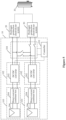
- the direct-current coupling hydrogen production system includes: at least one electricity generation system 10 (where Figure 1 merely shows an example in which the direct-current coupling hydrogen production system includes one electricity generation system 10), multiple hydrogen production electrolyzer systems 20 and at least one hydrogen storage tank 30.
- the electricity generation system 10 includes: a controller 101, N renewable energy systems 103, multiple conversion systems 102 and a power switching unit 104.
- N is an integer greater than 1.
- the hydrogen storage tank 30 is connected to a hydrogen outlet of a hydrogen production electrolyzer system 20 corresponding to the hydrogen storage tank 30 via a gas pipeline. Each of the hydrogen production electrolyzer system 20 outputs the produced hydrogen to the hydrogen storage tank 30 through the gas pipeline.
- the hydrogen storage tank 30 stores the hydrogen produced by the hydrogen production electrolyzer system 20.
- the hydrogen production electrolyzer system 20 is a lye hydrogen production electrolyzer system 20.
- the hydrogen production electrolyzer system 20 is another system, for example, a PEM (proton exchange membrane) hydrogen production electrolyzer system or a solid oxide hydrogen production electrolyzer system, depending on the actual applications, which is not limited herein and falls within the protection scope of the present disclosure.
- PEM proto exchange membrane
- all the multiple hydrogen production electrolyzer systems 20 share the hydrogen storage tank 30, to store hydrogen in a centralized manner. That is, respective hydrogen outlets of all the multiple hydrogen production electrolyzer systems 20 each are connected to a gas inlet of the hydrogen storage tank 30 via a gas pipeline.
- the multiple hydrogen production electrolyzer systems 20 are in one to one correspondence with the M hydrogen storage tanks 30, to store hydrogen in a distributed manner. That is, the hydrogen outlet of each of the hydrogen production electrolyzer systems 20 is connected to a gas inlet of the hydrogen storage tank 30 corresponding to the hydrogen production electrolyzer system 20 via a gas pipeline.
- some of the multiple hydrogen production electrolyzer systems 20 share the same hydrogen storage tank 30, to store hydrogen in a centralized manner.
- Hydrogen produced by a hydrogen production electrolyzer system 20 connected to one hydrogen storage tank 30 is stored separately from hydrogen produced by a hydrogen production electrolyzer system 20 connected to another hydrogen storage tank 30. That is, respective hydrogen outlets of the some of the multiple hydrogen production electrolyzer systems 20 each are connected to a hydrogen inlet of the same hydrogen storage tank 30 via gas pipelines.
- M is equal to five and the number of the hydrogen storage tanks 30 is two.
- Two of the five hydrogen production electrolyzer systems 20 share one of the two hydrogen storage tanks 30, and the other three hydrogen production electrolyzer systems 20 share the other of the two hydrogen storage tanks, which is not described in detail herein. Details in the case that the number of the hydrogen storage tank 30 is greater than 1 and less than M depend on the actual applications, and fall within the protection scope of the present application.
- the conversion system 102 and the power switching unit 104 both are arranged on an electrical energy transmission path from the N renewable energy systems 103 to the M hydrogen production electrolyzer systems 20.
- M is an integer greater than 1, and may be equal to N. It should be noted that in a case that the direct-current coupling hydrogen production system includes only one electricity generation system 10, the number of the hydrogen production electrolyzer system 20 is only M. In a case that the direct-current coupling hydrogen production system includes multiple electricity generation systems 10, each of the multiple electricity generation systems 10 is connected to M hydrogen production electrolyzer systems 20. In addition, the value of M may vary from electricity generation system 10 to electricity generation system 10, which depends on actual applications. In each electricity generation system 10, the power switching unit 104 includes N input ports and M output ports.
- the electricity generation system 10 includes N conversion systems 102. Electrical energy from the N renewable energy systems 103 is outputted to the M hydrogen production electrolyzer systems 20 through respective conversion systems 102 and the power switching unit 104 sequentially. That is, the N conversion systems 102 are arranged at the front end of the power switching unit 104. In this case, the power switching unit 104 collects the electrical energy inputted through the N input ports from the N renewable energy systems 103 connected to the N conversion systems 102 respectively, and then outputs the collected electrical energy to the M hydrogen production electrolyzer systems 20 through the M output ports.
- the electricity generation system 10 includes M conversion systems 102. Electrical energy from the N renewable energy systems 103 is outputted to the M hydrogen production electrolyzer systems 20 through the power switching unit 104 and the M conversion systems 102 sequentially, where the M hydrogen production electrolyzer systems 20 are in one-to-one correspondence with the M conversion systems 102. That is, the M conversion systems 102 are arranged at the back end of the power switching unit 104. In this case, the power switching unit 104 collects the electrical energy from the N renewable energy systems 103 respectively connected to the N input ports, and then outputs the collected electrical energy to the M hydrogen production electrolyzer systems 20 through the M output ports and the M conversion systems 102, respectively.
- the controller 101 is configured to: control the power switching unit 104 to supply the hydrogen production electrolyzer systems 20 through its output ports respectively corresponding to the hydrogen production electrolyzer systems 20 with the electrical energy received through its input ports, or collect the electrical energy received through its input ports and then supply the hydrogen production electrolyzer systems 20 through its output ports respectively corresponding to the hydrogen production electrolyzer systems 20 with the collected electrical energy, so that the hydrogen production electrolyzer systems 20 that receive the electrical energy each have sufficient power for hydrogen production, and the hydrogen production electrolyzer systems 20 that receive the electrical energy operate independently from each other.
- the controller 101 may be a communication host in each conversion system 102, or a system controller independently arranged in the direct-current coupling hydrogen production system, which is not limited herein. All technical solutions that the controller 101 is capable of communicating with and exchanging information with each of the conversion systems 102, determining the number of the to-be-powered hydrogen production electrolyzer systems 20 based on power detection, and controlling an on-off state of a switch device inside the power switching unit 104 fall within the protection scope of the present application.
- the power switching unit 104 collects electrical energy of multiple renewable energy systems 103 and outputs the collected electrical energy to the hydrogen production electrolyzer system 20 for supplying power for the hydrogen production electrolyzer system 20, so that the power for hydrogen production by the hydrogen production electrolyzer system 20 that receives the electrical energy is sufficient.
- the hydrogen production electrolyzer systems that receive the electrical energy operate independently from each other.
- the direct-current coupling hydrogen production system is appliable to distributed, centralized and other hydrogen production systems, and is also appliable to various scenarios such as roofs of residential buildings, roofs of industrial and commercial buildings, hills, deserts, and solar-fishery hybrid plants.
- the direct-current coupling hydrogen production system has a simple structure and strong versatility.
- the conversion system 102 is arranged at the front end of the power switching unit 104 in one example, and is arranged at the back end of the power switching unit 104 in another example. Structures in the two examples are described in detail below.
- the renewable energy system 103 includes a wind power system and/or a solar power system.
- Figure 1 shows an example in which the renewable energy system 103 includes both the wind power system and the solar power system.
- the conversion system 102 includes an AC/DC converter 201 connected to the wind power system.
- the conversion system 102 includes a DC/DC converter 202 connected to the solar power system.
- the solar power system includes a photovoltaic module 206 and a direct-current combiner box 204.
- One port of the direct-current combiner box 204 is connected to an output port of the photovoltaic module 206, and the other port of the direct-current combiner box 204 serves as an output port of the solar power system and is connected to an port of the DC/DC converter 202.
- the other port of the DC/DC converter 202 is connected to an input port of the power switching unit 104 corresponding to the DC/DC converter 202.
- the wind power system includes: a blade 205 and a generator 203. An output port of the blade 205 is connected to one port of the generator 203.
- the other port of the generator 203 serves as an output port of the wind power system, and is connected to an alternate-current end of the AC/DC converter 201.
- a direct-current end of the AC/DC converter 201 is connected to an input port of the power switching unit 104 corresponding to the AC/DC converter 201.
- the generator 203 is a permanent magnet synchronous generator or a doubly fed induction generator.
- Each of the DC/DC converter 202 and the AC/DC converter 201 may have an isolated or non-isolated topology, a boost, buck or boost-buck topology, a resonant or non-resonant topology, a full-bridge or half-bridge structure, a two-level topology or three-level topology.
- the structures of the DC/DC converter 202 and the AC/DC converter 201 depend on the actual applications and are not limited herein. All appropriate structures fall within the protection scope of the present application.
- the renewable energy system is not limited to the solar power system and/or the wind power system, and other kinds of the renewable energy system are also within the protection scope of the present disclosure.
- the power switching unit 104 in any of the above embodiments includes at least N-1 bus switch modules 33 and at least M-1 electrolyzer input switch modules 32.
- each electrolyzer input switch module 32 is connected to an output port Uout of the power switching unit 104 corresponding to the electrolyzer input switch module 32, and the other port of the electrolyzer input switch module 32 is connected to an input port Uin of the power switching unit 104 corresponding to the electrolyzer input switch module 32.
- Each bus switch module 33 is arranged between two input ports Uin.
- the bus switch module 33 may be arranged between two adjacent input ports Uin. Alternatively, the bus switch module 33 is arranged between two non-adjacent input ports Uin.
- the power switching unit 104 includes 3 input ports Uin, namely, Uin1, Uin2, and Uin3 in sequence.
- One bus switch module 33 is arranged between Uin1 and Uin2, and another bus switch module 33 is arranged between Uin2 and Uin3, for the power switching unit 104 to allocate the electrical energy from the renewable energy systems 103 connected to Uin1 and Uin2 directly or via respective conversion systems 102, and electrical energy from the renewable energy systems 103 connected to Uin2 and Uin3 directly or via respective conversion systems 102.
- the bus switch module 33 may also be arranged between two input ports Uin that are not adjacent to each other. That is, the bus switch module 33 may be arranged between Uin1 and Uin3, for the power switching unit 104 to allocate the electrical energy from the renewable energy systems 103 connected to Uin1 and Uin3 directly or via respective conversion systems 102.
- the arrangement of bus switch modules 33 depends on the actual applications and is not described in detail herein, and all appropriate arrangements fall within the protection scope of the present application.
- the power switching unit 104 starts outputting electrical energy to the hydrogen production electrolyzer system 20 by turning on the electrolyzer input switch module 32, and stops outputting electrical energy to the hydrogen production electrolyzer system 20 by turning off the electrolyzer input switch module 32.
- the electrical energy of the N renewable energy systems 103 is generally sufficient for hydrogen production by a single hydrogen production electrolyzer system 20
- one output port Uout of the power switching unit 104 is directly connected to one input port Uin of the power switching unit 104, and thus the power switching unit 104 includes only M-1 electrolyzer input switch modules 32.
- the M output ports Uout each may be connected to a corresponding input port Uin, which is not limited herein and falls within the protection scope of the present disclosure.
- one input port Uin may be connected to multiple electrolyzer input switch modules 32.
- M the number of output ports of the power switching unit 104
- one input port Uin may be connected to multiple electrolyzer input switch modules 32.
- two or more among the multiple electrolyzer input switch modules 32 sharing the same input port Uin are on simultaneously must be prevented when there is electrical energy inputted into the input port Uin.
- the power switching unit 104 may collect electrical energy from all the renewable energy systems 103 to provide electrical energy for only one hydrogen production electrolyzer system 20.
- the power switching unit 104 collects electrical energy from one or more of the renewable energy systems 103 to provide electrical energy for one hydrogen production electrolyzer system 20.
- the bus switch module 33 between paths for supplying electrical energy to respective hydrogen production electrolyzer systems 20 remains open, so that the hydrogen production electrolyzer systems 20 operate independently from each other, thereby avoiding circulation between the electrolyzer hydrogen production systems 20 receiving electrical energy.
- the conversion system 102 in the case that the conversion system 102 is arranged at the back end of the power switching unit 104 as shown in Figure 2 and the power switching unit 104 includes only one collection bus including at least N-1 bus switch modules 31, the renewable energy system 103 includes only one of the wind power system and the solar power system. Accordingly, the conversion system 102 includes only one of the DC/DC converter 202 and the AC/DC converter 201. That is, in a case that the renewable energy system 103 is a wind power system, the conversion system 102 is an AC/DC converter 201. In a case that the renewable energy system 103 is a solar power system, the conversion system 102 is a DC/DC converter 202.
- the renewable energy system 103 includes both the wind power system and the solar power system. Electrical energy from the wind power system and the solar power system are collected through the two collection buses 31, respectively.
- multiple small-capacity lye electrolyzers are connected in parallel through switches, and operation of each small-capacity lye electrolyzer is controlled based on power distribution.
- the multiple small-capacity lye electrolyzers are directly connected in parallel.
- a difference in temperature between small-capacity lye electrolyzers may result in a mismatch of the voltage/current between the small-capacity lye electrolyzers.
- circulation may occur between the small-capacity lye electrolyzers, resulting in low reliability of the system and even safety accidents.
- each bus switch module 33 in the power switching unit 104 is arranged between a joint where one input port Uin is connected to the collection bus 31 and another joint where another input port Uin is connected to the collection bus 31, so that electrical energy from the N renewable energy systems 103 are collected as required.
- electrical energy supplied to one hydrogen production electrolyzer system 20 connected to one end of a bus switch module 33 is independent of electrical energy supplied to another hydrogen production electrolyzer system 20 connected to the other end of the bus switch module 33 by closing the bus switch module 33. That is, the power switching unit 104 selectively collects electrical energy supplied to the hydrogen production electrolyzer systems 20, so that the parallel connection between the hydrogen production electrolyzer systems 20 is controllable. That is, the hydrogen production electrolyzer systems 20 are not directly connected in parallel.
- the mismatch of voltage/current between the hydrogen production electrolyzer systems 20 does not affect the operation of the direct-current coupling hydrogen production system, which further improves the reliability and safety of the direct-current coupling hydrogen production system.
- each hydrogen production electrolyzer system 20 discharges hydrogen at its cathode or intermediate electrode, depending on the actual applications, which is not limited herein and falls within the protection scope of the present disclosure.
- a gas pipeline between the hydrogen storage tank 30 and the hydrogen production electrolyzer system 20 is a metal pipeline or a non-metallic pipeline. The material of the gas pipeline depends on the actual applications, and thus is not limited herein and falls within the protection scope of the present disclosure.
- the hydrogen may be stored in a centralized or decentralized manner, depending on the actual applications, which is not limited herein and falls within the protection scope of the present disclosure.
- a structure of the electrolyzer input switch module 32 and a structure of the bus switch module 33 in the power switching unit 104 shown in Figure 3 vary with the manner in which the direct current coupling hydrogen production system discharges hydrogen, the material of the gas pipeline and the manner in which the hydrogen is stored, which is described below in detail.
- each of the electrolyzer input switch modules 32 and each of the bus switch modules 33 in the direct-current coupling hydrogen production system has a structure corresponding to the current case, which are not repeated here and fall within the protection scope of the present disclosure.
- the controllable switch may be a controllable mechanical switch such as a circuit breaker, a contactor and a relay, or a semiconductor switch such as an IGCT (intergrated gate commutated thyristors) and an IGBT (insulated gate bipolar transistors), depending on the actual applications, which is not limited herein and falls within the protection scope of the present disclosure.
- IGCT internal gate commutated thyristors
- IGBT insulated gate bipolar transistors
- the power switching unit 104 includes a controllable switch specific to a manner in which the direct-current coupling hydrogen production system discharges hydrogen, a gas pipeline and a manner in which hydrogen is stored, so that electrical energy intended for a hydrogen production electrolyzer system 20 is successfully supplied to the hydrogen production electrolyzer system 20, thereby improving the energy utilization and safety of the direct-current coupling hydrogen production system.
- a method for controlling a direct-current coupling hydrogen production system is provided according to an embodiment of the present disclosure.
- the method is applied to the controller of the direct-current coupling hydrogen production system according to any one of the above embodiments.
- the structure of the direct-current coupling hydrogen production system refers to the above embodiments, and thus is not repeated here.
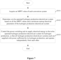
- the method for controlling a direct-current coupling hydrogen production system includes the following steps S101 to S 103.
- a to-be-operated hydrogen production electrolyzer system is determined based on all the MPPT values and a minimum startup electrical parameter of the hydrogen production electrolyzer system.
- the minimum startup electrical parameter is a minimum startup current or a minimum startup power. That is, in a case that an actual electrical parameter of the hydrogen production electrolyzer system is greater than or equal to the minimum startup electrical parameter, concentration of hydrogen produced by the hydrogen production electrolyzer system is sufficient for normal operation, and thus shutdown of the hydrogen production electrolyzer system due to low concentration of the produced hydrogen is impossible.
- Step S102 is describe in detail as follows. A sum of all the MPPT values is calculated. The sum is compared with the minimum startup electrical parameter, The number of the to-be-operated hydrogen production electrolyzer system is acquired. Then, the to-be-operated hydrogen production electrolyzer system is determined randomly or in a preset order. Alternatively, the to-be-operated hydrogen production electrolyzer system is determined directly. Details in step S 102 are not limited herein, and fall within the protection scope of the present disclosure.
- the power switching unit is controlled to provide electrical energy for the to-be-operated hydrogen production electrolyzer system for hydrogen production, so that all hydrogen production electrolyzer systems each are supplied with power sufficient for hydrogen production, and operate independently from each other.
- the electrical energy for hydrogen production received by the hydrogen production electrolyzer system is sufficient for normal operation of the hydrogen production electrolyzer system. That is, the concentration of hydrogen produced by the hydrogen production electrolyzer system is sufficient for normal operation.
- the power switching unit provides electrical energy for hydrogen production to the to-be-operated hydrogen production electrolyzer system, the hydrogen production electrolyzer system operates normally. There is no case of shutdown due to low concentration of the produced hydrogen.
- step S103 further includes: controlling a bus switch module and an electrolyzer input switch module in the power switching unit to be turned on, so that an input port is connected to an output port in the power switching unit.
- the to-be-operated hydrogen production electrolyzer systems operate independently from each other.
- the controllable switch S2 connected to one hydrogen production electrolyzer system 20 is controlled to be turned off, and the controllable switch S1 on the collection bus is controlled to be turned on, so that the electrical energy outputted from the two solar power systems is supplied to the same hydrogen production electrolyzer system 20 for hydrogen production.
- the number of the to-be-operated hydrogen production electrolyzer system is greater than 1, for each to-be-operated hydrogen production electrolyzer system, a bus switch module and an electrolyzer input switch module in a path for supplying power to the to-be-operated hydrogen production electrolyzer system are controlled to be turned on, and a bus switch module between paths is controlled to be turned off, so that an input port is connected to an output port of the power switching unit, and the to-be-operated hydrogen production electrolyzer systems operate independently from each other. As shown in Figure 8 , the number of the to-be-operated hydrogen production electrolyzer system is greater than 1. For example, hydrogen production electrolyzer systems 201 and 203 are determined to be operated.
- a bus switch module K1 is controlled to be turned on and K3 is controlled to be turned off, so that the hydrogen production electrolyzer system 201 operates.
- the hydrogen production electrolyzer system 202 is supplied with no electrical energy and thus fails to operate.
- a bus switch module K4 is controlled to be turned on, so that the hydrogen production electrolyzer system 201 operates.
- a bus switch module K2 is controlled to be turned off so that the hydrogen production electrolyzer systems 201 and 203 operate independently from each other, thereby preventing circulation between the hydrogen production electrolyzer systems 201 and 203.
- the to-be-operated hydrogen production electrolyzer system varies with the MPPT value.
- the concentration of hydrogen produced by the hydrogen production electrolyzer system is sufficient for normal operation.
- the method for controlling a direct-current coupling hydrogen production system according to this embodiment is simple in control and easy to implement, which is beneficial for popularization and use.
Landscapes
- Engineering & Computer Science (AREA)
- Power Engineering (AREA)
- Chemical & Material Sciences (AREA)
- Inorganic Chemistry (AREA)
- Chemical Kinetics & Catalysis (AREA)
- Electrochemistry (AREA)
- Materials Engineering (AREA)
- Metallurgy (AREA)
- Organic Chemistry (AREA)
- Electrolytic Production Of Non-Metals, Compounds, Apparatuses Therefor (AREA)
Abstract
Description
- The present application claims priority to
Chinese Patent Application No. 202010533744.5, titled "DIRECT-CURRENT COUPLING HYDROGEN PRODUCTION SYSTEM AND CONTROL METHOD THEREFOR", filed on June 12, 2020 - The present disclosure relates to the technical field of hydrogen production, and in particular to a direct current coupling hydrogen production system and a method for controlling the direct current coupling hydrogen production system.
- With increasing prominence of environmental issues, renewable energy sources attract attention, and solar power and wind power develop increasingly. Since the solar power and the wind power have disadvantages of instability and low energy density, the produced electrical energy does not match the electrical energy demanded by a grid. Further, the traditional chemical energy storage has disadvantages such as small capacity and short service life. Therefore, curtailment of solar, wind and electricity is inevitable in many areas, resulting in a serious waste of resources. As a completely pollution-free energy storage medium from production to end use, hydrogen may cooperate with the solar power and the wind power, to compensate for the disadvantages of the solar power and the wind power.
- In an actual renewable energy power station system, although the PEM (proton exchange membrane) electrolyzer successfully produces hydrogen at the power fluctuating from 0% to 100%, the technology thereof is not mature and its service life is short currently. In view of this, a lye electrolyzer system is still inevitable for large-scale hydrogen production in the renewable energy power station. However, the lye electrolyzer has limitations of minimum current/voltage. Generally, an actual current of the lye electrolyzer must be greater than about 30% of its rated current. Otherwise, the purity of hydrogen produced by the lye electrolyzer is low, and the lye electrolyzer may automatically shut down and even results in safety hazards.
- In view of this, an object of the present disclosure is to provide a direct-current coupling hydrogen production system and a method for controlling the direct-current coupling hydrogen production system, to solve the problem of low purity of hydrogen produced by a lye electrolyzer due to the fact that the actual current of the lye electrolyzer is extremely small, thereby improving energy utilization and safety of the direct-current coupling hydrogen production system.
- A direct-current coupling hydrogen production system is provided according to a first aspect of the present disclosure. The direct-current coupling hydrogen production system includes: at least one electricity generation system and multiple hydrogen production electrolyzer systems. The at least one electricity generation system each includes: a controller, N renewable energy systems, multiple conversion systems and a power switching unit, and N is an integer greater than 1. The multiple conversion systems and the power switching unit each are arranged on an electrical energy transmission path from the N renewable energy systems to M hydrogen production electrolyzer systems, and M is an integer greater than 1. The power switching unit includes N input ports and M output ports. The controller is configured to control the power switching unit to supply the multiple hydrogen production electrolyzer systems through the output ports of the power switching unit respectively corresponding to the multiple hydrogen production electrolyzer systems with electrical energy received through input ports of the power switching unit, or is configured to control the power switching unit to collect electrical energy received through the input ports of the power switching unit and to supply the multiple hydrogen production electrolyzer systems through the output ports of the power switching unit respectively corresponding to the hydrogen production electrolyzer systems with the collected electrical energy, so that the multiple hydrogen production electrolyzer systems that receive the electrical energy each have sufficient power for hydrogen production and operate independently from each other.
- Optionally, the multiple conversion systems in each of the at least one electricity generation system are arranged at a front end of the power switching unit, the number of the multiple conversion systems is N, output ports of the N renewable energy systems are connected to input ports of the N conversion systems in one-to-one correspondence, output ports of the N conversion systems are connected to the N input ports of the power switching unit in one-to-one correspondence, and the M output ports of the power switching unit are connected to input ports of the M hydrogen production electrolyzer systems in one-to-one correspondence.
- Optionally, the multiple conversion systems in each of the at least one electricity generation system are arranged at a back end of the power switching unit, the number of the multiple conversion systems is M, output ports of the N renewable energy systems are connected to the N input ports of the power switching unit in one-to-one correspondence, the M output ports of the power switching unit are connected to input ports of the M conversion systems in one-to-one correspondence, and output ports of the M conversion systems are connected to input ports of the M hydrogen production electrolyzer systems in one-to-one correspondence.
- Optionally, the direct-current coupling hydrogen production system further includes at least one hydrogen storage tank configured to store hydrogen produced by the multiple hydrogen production electrolyzer systems.
- Optionally, the multiple hydrogen production electrolyzer systems each are configured to discharge hydrogen at a cathode or an intermediate electrode of the hydrogen production electrolyzer system, and a gas pipeline between the hydrogen storage tank and each of the multiple hydrogen production electrolyzer systems is a metal pipeline or a non-metallic pipeline.
- Optionally, the number of the hydrogen storage tank is one, and the multiple hydrogen production electrolyzer systems are configured to share the one hydrogen storage tank to store hydrogen in a centralized manner. Alternatively, the number of the hydrogen storage tank is M, the multiple hydrogen production electrolyzer systems correspond to the M hydrogen storage tanks in one to one correspondence, to store hydrogen in a distributed manner. Alternatively, the number of the hydrogen storage tank is greater than 1 and less than M, some of the multiple hydrogen production electrolyzer systems are configured to share a same hydrogen storage tank. Hydrogen produced by a hydrogen production electrolyzer system among the multiple hydrogen production electrolyzer systems that is connected to one hydrogen storage tank is stored separately from hydrogen produced by a hydrogen production electrolyzer system among the multiple hydrogen production electrolyzer systems that is connected to another hydrogen storage tank.
- Optionally, the power switching unit includes at least N-1 bus switch modules and at least M-1 electrolyzer input switch modules. One port of each of the M-1 electrolyzer input switch modules is connected to an output port among the M output ports of the power switching unit, and the other port of the electrolyzer input switch module is connected to an input port among the N input ports of the power switching unit. Each of the bus switch modules is arranged between two input ports among the N input ports of the power switching unit.
- Optionally, in a case that hydrogen is discharged at a cathode, a gas pipeline is a metal pipeline, and hydrogen is stored in a centralized manner, each of the M-1 electrolyzer input switch modules includes a controllable switch arranged on an anode branch, and each of the N-1 bus switch modules includes a controllable switch arranged on a positive branch. In a case that hydrogen is discharged at a cathode and a gas pipeline is a non-metal pipeline, or hydrogen is discharged at an immediate electrode, each of the M-1 electrolyzer input switch modules includes a controllable switch arranged on anode branch and a controllable switch arranged on a cathode branch, and each of the N-1 bus switch modules includes a controllable switch arranged on a positive branch and a controllable switch arranged on a negative branch.
- Optionally, the controllable switch is a controllable mechanical switch or a semiconductor switch.
- Optionally, for each of the N renewable energy systems, the renewable energy system includes a wind power system and/or a solar power system. In a case that the renewable energy system includes the wind power system, a conversion system among the multiple conversion systems that corresponds to the renewable energy system includes an AC/DC converter connected to the wind power system. In a case that the renewable energy system includes the solar power system, a conversion system among the multiple conversion systems that corresponds to the renewable energy system includes a DC/DC converter connected to the solar power system.
- Optionally, the solar power system includes a photovoltaic module and a direct-current combiner box, one port of the direct-current combiner box is connected to an output port of the photovoltaic module, and the other port of the direct-current combiner box serves as an output port of the solar power system. The wind power system includes a blade and a permanent magnet synchronous generator or doubly fed induction generator, an output port of the blade is connected to one port of the permanent magnet synchronous generator or doubly fed induction generator, and the other port of the permanent magnet synchronous generator or doubly fed induction generator serves as an output port of the wind power system.
- Optionally, the controller is a communication host in each of the multiple conversion systems. Alternatively, the controller is a system controller independently arranged in the direct-current coupling hydrogen production system.
- A method for controlling a direct-current coupling hydrogen production system is provided according to a second aspect of the present disclosure. The method is applied to a controller of the direct-current coupling hydrogen production system disclosed according to the first aspect of the present disclosure. The method includes: acquiring a maximum power point tracking MPPT value of each conversion system in the direct-current coupling hydrogen production system; determining a to-be-operated hydrogen production electrolyzer system based on all the MPPT values and a minimum startup electrical parameter of a hydrogen production electrolyzer system in the direct-current coupling hydrogen production system; and controlling the power switching unit in the direct-current coupling hydrogen production system to supply electrical energy to the to-be-operated hydrogen production electrolyzer system for hydrogen production, so that electrical energy received by each to-be-operated hydrogen production electrolyzer system is sufficient for hydrogen production, and all the to-be-operated hydrogen production electrolyzer system operates independently.
- Optionally, the power switching unit includes at least M-1 electrolyzer input switch modules and at least N-1 bus switch modules, and the controlling the power switching unit in the direct-current coupling hydrogen production system to supply electrical energy to the to-be-operated hydrogen production electrolyzer system for hydrogen production, so that electrical energy received by each to-be-operated hydrogen production electrolyzer system is sufficient for hydrogen production, and all the to-be-operated hydrogen production electrolyzer system operates independently includes: controlling a bus switch module and an electrolyzer input switch module in the power switching unit to be turned on to connect an input port to an output port of the power switching unit so that all the to-be-operated hydrogen production electrolyzer system operates independently.
- Optionally, the controlling a bus switch module and an electrolyzer input switch module in the power switching unit to be turned on to connect an input port to an output port of the power switching unit so that all the to-be-operated hydrogen production electrolyzer system operates independently includes: controlling, in a case that the number of the to-be-operated hydrogen production electrolyzer system is 1, all bus switch modules and an electrolyzer input switch module that is connected to the to-be-operated hydrogen production electrolyzer system to be turned on, and all other electrolyzer input switch modules to be turned off, so that all input ports of the power switching unit each are connected to the output port of the power switching unit, and the to-be-operated hydrogen production electrolyzer system operates independently; and controlling, for each to-be-operated hydrogen production electrolyzer system in a case that the number of the to-be-operated hydrogen production electrolyzer system is greater than 1, a bus switch module and an electrolyzer input switch module in a path for supplying electrical energy to the to-be-operated hydrogen production electrolyzer system to be turned on, and a bus switch module between paths to be turned off, so that an input port is connected to an output port of the power switching unit, and the to-be-operated hydrogen production electrolyzer systems operate independently from each other.
- It can be seen from the above technical solutions that, the direct-current coupling hydrogen production system according to the present disclosure includes: at least one electricity generation system and multiple hydrogen production electrolyzer systems. In each of the at least one electricity generation system, multiple conversion systems and a power switching unit each are arranged on an electrical energy transmission path from the N renewable energy systems to M hydrogen production electrolyzer systems, and M is an integer greater than 1. The power switching unit includes N input ports and M output ports. The controller is configured to control the power switching unit to supply the multiple hydrogen production electrolyzer systems through the output ports of the power switching unit respectively corresponding to the multiple hydrogen production electrolyzer systems with electrical energy received through input ports of the power switching unit, or is configured to control the power switching unit to collect electrical energy received through the input ports of the power switching unit and to supply the multiple hydrogen production electrolyzer systems through the output ports of the power switching unit respectively corresponding to the hydrogen production electrolyzer systems with the collected electrical energy, so that the multiple hydrogen production electrolyzer systems that receive the electrical energy each have sufficient power for hydrogen production and operate independently from each other. In a case that electrical energy of a single renewable energy system is insufficient to produce hydrogen by a single hydrogen production electrolyzer system, the power switching unit collects electrical energy of multiple renewable energy systems and outputs the collected electrical energy to the hydrogen production electrolyzer system for supplying power for the hydrogen production electrolyzer system, so that the power for hydrogen production by the hydrogen production electrolyzer system that receives the electrical energy is sufficient. Further, the hydrogen production electrolyzer systems that receive the electrical energy operate independently from each other. Therefore, the problem of lower purity of hydrogen produced by the hydrogen production electrolyzer system due to the fact that the actual current of the hydrogen production electrolyzer system is extremely small and the problem of circulation due to the fact that hydrogen production electrolyzer systems that receive electrical energy are not independent of each other are solved, thereby improving the energy utilization and safety of the direct-current coupling hydrogen production system.
-
-
Figure 1 is a schematic diagram illustrating a direct-current coupling hydrogen production system according to an embodiment of the present disclosure; -
Figure 2 is a schematic diagram illustrating the direct-current coupling hydrogen production system according to another embodiment of the present disclosure; -
Figure 3 is a schematic diagram illustrating a power switching unit in the direct-current coupling hydrogen production system according to an embodiment of the present disclosure; -
Figure 4 is a schematic diagram illustrating the direct-current coupling hydrogen production system according to another embodiment of the present disclosure; -
Figure 5 is a schematic diagram illustrating the direct-current coupling hydrogen production system according to another embodiment of the present disclosure; -
Figure 6 is a schematic diagram illustrating the direct-current coupling hydrogen production system according to another embodiment of the present disclosure; -
Figure 7 is a flowchart illustrating a method for controlling the direct-current coupling hydrogen production system according to an embodiment of the present disclosure; and -
Figure 8 is a schematic diagram illustrating the direct-current coupling hydrogen production system according to another embodiment of the present disclosure. - The technical solutions in the embodiments of the present disclosure are described clearly and completely in conjunction with the drawings of the embodiments of the present disclosure hereinafter, so that the objects, technical solutions and advantages of the embodiments of the present disclosure are clearer. It is apparent that the described embodiments are only some rather than all embodiments of the present disclosure. All other embodiments obtained by those skilled in the art based on the embodiments of the present disclosure without any creative efforts fall within the protection scope of the present disclosure.
- In this specification, terms "comprise", "include", or any other variants thereof are intended to encompass a non-exclusive inclusion, such that a process, method, article, or device including a series of elements includes not only those elements but also other elements that are not explicitly listed, or includes the elements that are inherent to the process, method, article, or device. Unless expressively limited otherwise, a process, method, article or device limited by "comprising/including a(n) ..." does not exclude existence of another identical element in the process, method, article or device.
- A direct-current coupling hydrogen production system is provided according to the embodiments of the present disclosure, so as to solve the problem of low purity of hydrogen produced by a hydrogen production electrolyzer system due to the fact that an actual current of the hydrogen production electrolyzer system is extremely small in the conventional technology, thereby improving energy utilization and safety of the direct-current coupling hydrogen production system.
- Referring to
Figure 1 , the direct-current coupling hydrogen production system includes: at least one electricity generation system 10 (whereFigure 1 merely shows an example in which the direct-current coupling hydrogen production system includes one electricity generation system 10), multiple hydrogenproduction electrolyzer systems 20 and at least onehydrogen storage tank 30. Theelectricity generation system 10 includes: acontroller 101, Nrenewable energy systems 103,multiple conversion systems 102 and apower switching unit 104. N is an integer greater than 1. Thehydrogen storage tank 30 is connected to a hydrogen outlet of a hydrogenproduction electrolyzer system 20 corresponding to thehydrogen storage tank 30 via a gas pipeline. Each of the hydrogenproduction electrolyzer system 20 outputs the produced hydrogen to thehydrogen storage tank 30 through the gas pipeline. Thehydrogen storage tank 30 stores the hydrogen produced by the hydrogenproduction electrolyzer system 20. The hydrogenproduction electrolyzer system 20 is a lye hydrogenproduction electrolyzer system 20. Alternatively, the hydrogenproduction electrolyzer system 20 is another system, for example, a PEM (proton exchange membrane) hydrogen production electrolyzer system or a solid oxide hydrogen production electrolyzer system, depending on the actual applications, which is not limited herein and falls within the protection scope of the present disclosure. - In practice, in a case that the number of the
hydrogen storage tank 30 is one, all the multiple hydrogenproduction electrolyzer systems 20 share thehydrogen storage tank 30, to store hydrogen in a centralized manner. That is, respective hydrogen outlets of all the multiple hydrogenproduction electrolyzer systems 20 each are connected to a gas inlet of thehydrogen storage tank 30 via a gas pipeline. In a case that the number of thehydrogen storage tank 30 is M, the multiple hydrogenproduction electrolyzer systems 20 are in one to one correspondence with the Mhydrogen storage tanks 30, to store hydrogen in a distributed manner. That is, the hydrogen outlet of each of the hydrogenproduction electrolyzer systems 20 is connected to a gas inlet of thehydrogen storage tank 30 corresponding to the hydrogenproduction electrolyzer system 20 via a gas pipeline. In a case that the number of thehydrogen storage tank 30 is greater than 1 and less than M, some of the multiple hydrogenproduction electrolyzer systems 20 share the samehydrogen storage tank 30, to store hydrogen in a centralized manner. Hydrogen produced by a hydrogenproduction electrolyzer system 20 connected to onehydrogen storage tank 30 is stored separately from hydrogen produced by a hydrogenproduction electrolyzer system 20 connected to anotherhydrogen storage tank 30. That is, respective hydrogen outlets of the some of the multiple hydrogenproduction electrolyzer systems 20 each are connected to a hydrogen inlet of the samehydrogen storage tank 30 via gas pipelines. For example, M is equal to five and the number of thehydrogen storage tanks 30 is two. Two of the five hydrogenproduction electrolyzer systems 20 share one of the twohydrogen storage tanks 30, and the other three hydrogenproduction electrolyzer systems 20 share the other of the two hydrogen storage tanks, which is not described in detail herein. Details in the case that the number of thehydrogen storage tank 30 is greater than 1 and less than M depend on the actual applications, and fall within the protection scope of the present application. - As shown in
Figures 1 and2 , theconversion system 102 and thepower switching unit 104 both are arranged on an electrical energy transmission path from the Nrenewable energy systems 103 to the M hydrogenproduction electrolyzer systems 20. M is an integer greater than 1, and may be equal to N. It should be noted that in a case that the direct-current coupling hydrogen production system includes only oneelectricity generation system 10, the number of the hydrogenproduction electrolyzer system 20 is only M. In a case that the direct-current coupling hydrogen production system includes multipleelectricity generation systems 10, each of the multipleelectricity generation systems 10 is connected to M hydrogenproduction electrolyzer systems 20. In addition, the value of M may vary fromelectricity generation system 10 toelectricity generation system 10, which depends on actual applications. In eachelectricity generation system 10, thepower switching unit 104 includes N input ports and M output ports. - As shown in
Figure 1 , theelectricity generation system 10 includesN conversion systems 102. Electrical energy from the Nrenewable energy systems 103 is outputted to the M hydrogenproduction electrolyzer systems 20 throughrespective conversion systems 102 and thepower switching unit 104 sequentially. That is, theN conversion systems 102 are arranged at the front end of thepower switching unit 104. In this case, thepower switching unit 104 collects the electrical energy inputted through the N input ports from the Nrenewable energy systems 103 connected to theN conversion systems 102 respectively, and then outputs the collected electrical energy to the M hydrogenproduction electrolyzer systems 20 through the M output ports. - Alternatively, as shown in
Figure 2 , theelectricity generation system 10 includesM conversion systems 102. Electrical energy from the Nrenewable energy systems 103 is outputted to the M hydrogenproduction electrolyzer systems 20 through thepower switching unit 104 and theM conversion systems 102 sequentially, where the M hydrogenproduction electrolyzer systems 20 are in one-to-one correspondence with theM conversion systems 102. That is, theM conversion systems 102 are arranged at the back end of thepower switching unit 104. In this case, thepower switching unit 104 collects the electrical energy from the Nrenewable energy systems 103 respectively connected to the N input ports, and then outputs the collected electrical energy to the M hydrogenproduction electrolyzer systems 20 through the M output ports and theM conversion systems 102, respectively. - In both the case that the
conversion system 102 is arranged at the front end of thepower switching unit 104 and the case that theconversion system 102 is arranged at the back end of thepower switching unit 104 in theelectricity generation system 10, thecontroller 101 is configured to: control thepower switching unit 104 to supply the hydrogenproduction electrolyzer systems 20 through its output ports respectively corresponding to the hydrogenproduction electrolyzer systems 20 with the electrical energy received through its input ports, or collect the electrical energy received through its input ports and then supply the hydrogenproduction electrolyzer systems 20 through its output ports respectively corresponding to the hydrogenproduction electrolyzer systems 20 with the collected electrical energy, so that the hydrogenproduction electrolyzer systems 20 that receive the electrical energy each have sufficient power for hydrogen production, and the hydrogenproduction electrolyzer systems 20 that receive the electrical energy operate independently from each other. - In practice, the
controller 101 may be a communication host in eachconversion system 102, or a system controller independently arranged in the direct-current coupling hydrogen production system, which is not limited herein. All technical solutions that thecontroller 101 is capable of communicating with and exchanging information with each of theconversion systems 102, determining the number of the to-be-powered hydrogenproduction electrolyzer systems 20 based on power detection, and controlling an on-off state of a switch device inside thepower switching unit 104 fall within the protection scope of the present application. - With the direct-current coupling hydrogen production system according to this embodiment, in a case that electrical energy of a single
renewable energy system 103 is insufficient to produce hydrogen by a single hydrogenproduction electrolyzer system 20, thepower switching unit 104 collects electrical energy of multiplerenewable energy systems 103 and outputs the collected electrical energy to the hydrogenproduction electrolyzer system 20 for supplying power for the hydrogenproduction electrolyzer system 20, so that the power for hydrogen production by the hydrogenproduction electrolyzer system 20 that receives the electrical energy is sufficient. Further, the hydrogen production electrolyzer systems that receive the electrical energy operate independently from each other. Therefore, the problem of lower purity of hydrogen produced by the hydrogenproduction electrolyzer system 20 due to the fact that the actual current of the hydrogenproduction electrolyzer system 20 is extremely small and the problem of circulation due to the fact that hydrogen production electrolyzer systems that receive electrical energy are not independent of each other are solved, thereby improving the energy utilization and safety of the direct-current coupling hydrogen production system. In addition, the direct-current coupling hydrogen production system is appliable to distributed, centralized and other hydrogen production systems, and is also appliable to various scenarios such as roofs of residential buildings, roofs of industrial and commercial buildings, hills, deserts, and solar-fishery hybrid plants. The direct-current coupling hydrogen production system has a simple structure and strong versatility. - It can be seen from the above description that in the
electricity generation system 10, theconversion system 102 is arranged at the front end of thepower switching unit 104 in one example, and is arranged at the back end of thepower switching unit 104 in another example. Structures in the two examples are described in detail below. - (1) As shown in
Figure 1 , in theelectricity generation system 10, theconversion system 102 is arranged at the front end of thepower switching unit 104. The number ofconversion systems 102 is N. Output ports of the Nrenewable energy systems 103 are connected to input ports of theN conversion systems 102 in one-to-one correspondence. Output ports of theN conversion systems 102 are connected to the N input ports of thepower switching unit 104 in one-to-one correspondence. The M output ports of thepower switching unit 104 are connected to input ports of the M hydrogenproduction electrolyzer systems 20 in one-to-one correspondence. - (2) As shown in
Figure 2 , in theelectricity generation system 10, theconversion system 102 is arranged at the back end of thepower switching unit 104. The number of theconversion systems 102 is M. Output ports of the Nrenewable energy systems 103 are connected to the N input ports of thepower switching unit 104 in one-to-one correspondence. The M output ports of thepower switching unit 104 are connected to input ports of theM conversion systems 102 in one-to-one correspondence. Output ports of theM conversion systems 102 are connected to input ports of the M hydrogenproduction electrolyzer systems 20 in one-to-one correspondence. - In practice, the
renewable energy system 103 includes a wind power system and/or a solar power system.Figure 1 shows an example in which therenewable energy system 103 includes both the wind power system and the solar power system. In a case that therenewable energy system 103 includes a wind power system, theconversion system 102 includes an AC/DC converter 201 connected to the wind power system. In a case that therenewable energy system 103 includes a solar power system, theconversion system 102 includes a DC/DC converter 202 connected to the solar power system. - Referring to
Figure 1 , the solar power system includes aphotovoltaic module 206 and a direct-current combiner box 204. One port of the direct-current combiner box 204 is connected to an output port of thephotovoltaic module 206, and the other port of the direct-current combiner box 204 serves as an output port of the solar power system and is connected to an port of the DC/DC converter 202. The other port of the DC/DC converter 202 is connected to an input port of thepower switching unit 104 corresponding to the DC/DC converter 202. The wind power system includes: ablade 205 and agenerator 203. An output port of theblade 205 is connected to one port of thegenerator 203. The other port of thegenerator 203 serves as an output port of the wind power system, and is connected to an alternate-current end of the AC/DC converter 201. A direct-current end of the AC/DC converter 201 is connected to an input port of thepower switching unit 104 corresponding to the AC/DC converter 201. Thegenerator 203 is a permanent magnet synchronous generator or a doubly fed induction generator. - Each of the DC/
DC converter 202 and the AC/DC converter 201 may have an isolated or non-isolated topology, a boost, buck or boost-buck topology, a resonant or non-resonant topology, a full-bridge or half-bridge structure, a two-level topology or three-level topology. The structures of the DC/DC converter 202 and the AC/DC converter 201 depend on the actual applications and are not limited herein. All appropriate structures fall within the protection scope of the present application. The renewable energy system is not limited to the solar power system and/or the wind power system, and other kinds of the renewable energy system are also within the protection scope of the present disclosure. - Optionally, referring to
Figure 3 , thepower switching unit 104 in any of the above embodiments includes at least N-1bus switch modules 33 and at least M-1 electrolyzerinput switch modules 32. - One port of each electrolyzer
input switch module 32 is connected to an output port Uout of thepower switching unit 104 corresponding to the electrolyzerinput switch module 32, and the other port of the electrolyzerinput switch module 32 is connected to an input port Uin of thepower switching unit 104 corresponding to the electrolyzerinput switch module 32. Eachbus switch module 33 is arranged between two input ports Uin. - The
bus switch module 33 may be arranged between two adjacent input ports Uin. Alternatively, thebus switch module 33 is arranged between two non-adjacent input ports Uin. For example, thepower switching unit 104 includes 3 input ports Uin, namely, Uin1, Uin2, and Uin3 in sequence. Onebus switch module 33 is arranged between Uin1 and Uin2, and anotherbus switch module 33 is arranged between Uin2 and Uin3, for thepower switching unit 104 to allocate the electrical energy from therenewable energy systems 103 connected to Uin1 and Uin2 directly or viarespective conversion systems 102, and electrical energy from therenewable energy systems 103 connected to Uin2 and Uin3 directly or viarespective conversion systems 102. Thebus switch module 33 may also be arranged between two input ports Uin that are not adjacent to each other. That is, thebus switch module 33 may be arranged between Uin1 and Uin3, for thepower switching unit 104 to allocate the electrical energy from therenewable energy systems 103 connected to Uin1 and Uin3 directly or viarespective conversion systems 102. The arrangement ofbus switch modules 33 depends on the actual applications and is not described in detail herein, and all appropriate arrangements fall within the protection scope of the present application. - Specifically, the
power switching unit 104 starts outputting electrical energy to the hydrogenproduction electrolyzer system 20 by turning on the electrolyzerinput switch module 32, and stops outputting electrical energy to the hydrogenproduction electrolyzer system 20 by turning off the electrolyzerinput switch module 32. In practice, since the electrical energy of the Nrenewable energy systems 103 is generally sufficient for hydrogen production by a single hydrogenproduction electrolyzer system 20, one output port Uout of thepower switching unit 104 is directly connected to one input port Uin of thepower switching unit 104, and thus thepower switching unit 104 includes only M-1 electrolyzerinput switch modules 32. Alternatively, the M output ports Uout each may be connected to a corresponding input port Uin, which is not limited herein and falls within the protection scope of the present disclosure. It should be noted that, in a case that the number of output ports of thepower switching unit 104 is greater than the number of input ports of thepower switching unit 104, that is, M>N, one input port Uin may be connected to multiple electrolyzerinput switch modules 32. In order to avoid circulation between electrolyzer hydrogen production systems due to parallel connection, a case that two or more among the multiple electrolyzerinput switch modules 32 sharing the same input port Uin are on simultaneously must be prevented when there is electrical energy inputted into the input port Uin. - That is, the
power switching unit 104 may collect electrical energy from all therenewable energy systems 103 to provide electrical energy for only one hydrogenproduction electrolyzer system 20. Alternatively, thepower switching unit 104 collects electrical energy from one or more of therenewable energy systems 103 to provide electrical energy for one hydrogenproduction electrolyzer system 20. In this case, thebus switch module 33 between paths for supplying electrical energy to respective hydrogenproduction electrolyzer systems 20 remains open, so that the hydrogenproduction electrolyzer systems 20 operate independently from each other, thereby avoiding circulation between the electrolyzerhydrogen production systems 20 receiving electrical energy. In a case of M=N, the Nrenewable energy systems 103 supply electrical energy to the M hydrogenproduction electrolyzer systems 20 separately. - It should be noted that, in the case that the
conversion system 102 is arranged at the back end of thepower switching unit 104 as shown inFigure 2 and thepower switching unit 104 includes only one collection bus including at least N-1 bus switch modules 31, therenewable energy system 103 includes only one of the wind power system and the solar power system. Accordingly, theconversion system 102 includes only one of the DC/DC converter 202 and the AC/DC converter 201. That is, in a case that therenewable energy system 103 is a wind power system, theconversion system 102 is an AC/DC converter 201. In a case that therenewable energy system 103 is a solar power system, theconversion system 102 is a DC/DC converter 202. In a case that thepower switching unit 104 includes two collection buses 31 each including at least N-1 bus switch modules, therenewable energy system 103 includes both the wind power system and the solar power system. Electrical energy from the wind power system and the solar power system are collected through the two collection buses 31, respectively. - It should be noted that according to the conventional technology multiple small-capacity lye electrolyzers are connected in parallel through switches, and operation of each small-capacity lye electrolyzer is controlled based on power distribution. In this case, the multiple small-capacity lye electrolyzers are directly connected in parallel. A difference in temperature between small-capacity lye electrolyzers may result in a mismatch of the voltage/current between the small-capacity lye electrolyzers. In this case, circulation may occur between the small-capacity lye electrolyzers, resulting in low reliability of the system and even safety accidents.
- In this embodiment, each
bus switch module 33 in thepower switching unit 104 is arranged between a joint where one input port Uin is connected to the collection bus 31 and another joint where another input port Uin is connected to the collection bus 31, so that electrical energy from the Nrenewable energy systems 103 are collected as required. In addition, electrical energy supplied to one hydrogenproduction electrolyzer system 20 connected to one end of abus switch module 33 is independent of electrical energy supplied to another hydrogenproduction electrolyzer system 20 connected to the other end of thebus switch module 33 by closing thebus switch module 33. That is, thepower switching unit 104 selectively collects electrical energy supplied to the hydrogenproduction electrolyzer systems 20, so that the parallel connection between the hydrogenproduction electrolyzer systems 20 is controllable. That is, the hydrogenproduction electrolyzer systems 20 are not directly connected in parallel. Furthermore, the mismatch of voltage/current between the hydrogenproduction electrolyzer systems 20 does not affect the operation of the direct-current coupling hydrogen production system, which further improves the reliability and safety of the direct-current coupling hydrogen production system. In practice, there is a case that multiple electrolyzerhydrogen production systems 20 are directly connected in parallel to the collection bus 31 to receive the same electrical energy. In this case, circulation may occur between the hydrogenproduction electrolyzer systems 20 receiving the electrical energy. - In practice, each hydrogen
production electrolyzer system 20 discharges hydrogen at its cathode or intermediate electrode, depending on the actual applications, which is not limited herein and falls within the protection scope of the present disclosure. A gas pipeline between thehydrogen storage tank 30 and the hydrogenproduction electrolyzer system 20 is a metal pipeline or a non-metallic pipeline. The material of the gas pipeline depends on the actual applications, and thus is not limited herein and falls within the protection scope of the present disclosure. The hydrogen may be stored in a centralized or decentralized manner, depending on the actual applications, which is not limited herein and falls within the protection scope of the present disclosure. - A structure of the electrolyzer
input switch module 32 and a structure of thebus switch module 33 in thepower switching unit 104 shown inFigure 3 vary with the manner in which the direct current coupling hydrogen production system discharges hydrogen, the material of the gas pipeline and the manner in which the hydrogen is stored, which is described below in detail. - (1) The hydrogen
production electrolyzer system 20 discharges hydrogen at its cathode, the gas pipeline is a metal pipeline, and the hydrogen is stored in the centralized manner. As shown inFigure 4 (which illustrates an example in which therenewable energy system 103 includes only the solar power system, the number of therenewable energy systems 103 is 2, and theconversion system 102 is arranged at the front end of the power switching unit 104), each electrolyzerinput switch module 32 includes a controllable switch (S2 shown inFigure 4 ) arranged on a branch of an anode, and eachbus switch module 33 includes a controllable switch (S 1 shown inFigure 4 ) arranged on a positive branch of the collection bus. The cathodes at the input ends of all the hydrogenproduction electrolyzer systems 20 are equipotential.
As shown inFigure 4 , in the case that the number of the hydrogenproduction electrolyzer systems 20 is two, a controllable switch S2 is arranged between an anode at an input end of one hydrogenproduction electrolyzer system 20 and the positive branch of the collection bus (31 inFigure 3 ), and acontrollable switch S 1 is arranged, on the positive branch of the collection bus, between a positive electrode at an output end of one DC/DC converter 202 and a positive electrode at an output end of the other DC/DC converter 202. No controllable switch is arranged between a cathode at the input end of each hydrogenproduction electrolyzer system 20 and the negative branch of the collection bus, and no controllable switch is arranged on the negative branch of the collection bus. It should be noted that a controllable switch may also be arranged between an anode at an input end of the other hydrogenproduction electrolyzer system 20 and the positive branch of the collection bus. - (2) The hydrogen
production electrolyzer system 20 discharges hydrogen at its cathode, the gas pipeline is a non-metal pipeline, and the hydrogen is stored in the centralized or decentralized manner, or the hydrogenproduction electrolyzer system 20 discharges hydrogen at its immediate electrode, the gas pipeline is a metal pipeline or non-metallic pipeline, and the hydrogen is stored in the centralized or decentralized manner, as shown inFigure 5 (which illustrates an example in which the hydrogen is stored in the centralized manner) andFigure 6 (which illustrates an example in which the hydrogen is stored in the decentralized manner). Each electrolyzerinput switch module 32 in thepower switching unit 104 shown inFigure 3 includes a controllable switch arranged on a branch of an anode and a controllable switch arranged on a branch of a cathode. Eachbus switch module 33 in thepower switching unit 104 shown inFigure 3 includes a controllable switch arranged on a positive branch of the collection bus and a controllable switch arranged on a negative branch of the collection bus. In this case, cathodes at input ends of all the hydrogenproduction electrolyzer systems 20 are not equipotential. It should be noted that,Figures 5 and6 each illustrate on an only example in which therenewable energy system 103 includes a solar power system only, the number of therenewable energy systems 103 is two, and theconversion system 102 is arranged at the front end of thepower switching unit 104. - It should be noted that in a case that the direct-current coupling hydrogen production system discharges hydrogen in another manner, the gas pipeline is made of another material, and the hydrogen is stored in another manner in additional to the cases illustrated in (1) or (2), each of the electrolyzer
input switch modules 32 and each of thebus switch modules 33 in the direct-current coupling hydrogen production system has a structure corresponding to the current case, which are not repeated here and fall within the protection scope of the present disclosure. - The controllable switch may be a controllable mechanical switch such as a circuit breaker, a contactor and a relay, or a semiconductor switch such as an IGCT (intergrated gate commutated thyristors) and an IGBT (insulated gate bipolar transistors), depending on the actual applications, which is not limited herein and falls within the protection scope of the present disclosure.
- In this embodiment, the
power switching unit 104 includes a controllable switch specific to a manner in which the direct-current coupling hydrogen production system discharges hydrogen, a gas pipeline and a manner in which hydrogen is stored, so that electrical energy intended for a hydrogenproduction electrolyzer system 20 is successfully supplied to the hydrogenproduction electrolyzer system 20, thereby improving the energy utilization and safety of the direct-current coupling hydrogen production system. - A method for controlling a direct-current coupling hydrogen production system is provided according to an embodiment of the present disclosure. The method is applied to the controller of the direct-current coupling hydrogen production system according to any one of the above embodiments. The structure of the direct-current coupling hydrogen production system refers to the above embodiments, and thus is not repeated here.
- Referring to
Figure 7 , the method for controlling a direct-current coupling hydrogen production system includes the following steps S101 toS 103. - In S101, an MPPT value of each conversion system is acquired.
- In S102, a to-be-operated hydrogen production electrolyzer system is determined based on all the MPPT values and a minimum startup electrical parameter of the hydrogen production electrolyzer system.
- The minimum startup electrical parameter is a minimum startup current or a minimum startup power. That is, in a case that an actual electrical parameter of the hydrogen production electrolyzer system is greater than or equal to the minimum startup electrical parameter, concentration of hydrogen produced by the hydrogen production electrolyzer system is sufficient for normal operation, and thus shutdown of the hydrogen production electrolyzer system due to low concentration of the produced hydrogen is impossible.
- Step S102 is describe in detail as follows. A sum of all the MPPT values is calculated. The sum is compared with the minimum startup electrical parameter, The number of the to-be-operated hydrogen production electrolyzer system is acquired. Then, the to-be-operated hydrogen production electrolyzer system is determined randomly or in a preset order. Alternatively, the to-be-operated hydrogen production electrolyzer system is determined directly. Details in
step S 102 are not limited herein, and fall within the protection scope of the present disclosure. - In S103, the power switching unit is controlled to provide electrical energy for the to-be-operated hydrogen production electrolyzer system for hydrogen production, so that all hydrogen production electrolyzer systems each are supplied with power sufficient for hydrogen production, and operate independently from each other.
- It should be noted that, after the above steps, the electrical energy for hydrogen production received by the hydrogen production electrolyzer system is sufficient for normal operation of the hydrogen production electrolyzer system. That is, the concentration of hydrogen produced by the hydrogen production electrolyzer system is sufficient for normal operation. As long as the power switching unit provides electrical energy for hydrogen production to the to-be-operated hydrogen production electrolyzer system, the hydrogen production electrolyzer system operates normally. There is no case of shutdown due to low concentration of the produced hydrogen.
- In practice, in a case that the power switching unit includes at least M-1 electrolyzer input switch modules and at least N-1 bus switch modules, step S103 further includes: controlling a bus switch module and an electrolyzer input switch module in the power switching unit to be turned on, so that an input port is connected to an output port in the power switching unit. The to-be-operated hydrogen production electrolyzer systems operate independently from each other.
- In practice, in a case that the number of the to-be-operated hydrogen production electrolyzer system is 1, all the bus switch modules and the electrolyzer input switch module that is connected to the to-be-operated hydrogen production electrolyzer system are controlled to be turned on, and all other electrolyzer input switch modules are controlled to be turned off, so that all the input ports each are connected to the output port of the power switching unit, and the to-be-operated hydrogen production electrolyzer system operates independently from each other. For example, as shown in
Figure 4 , in a case that the electrical energy outputted from theelectricity generation system 10 is insufficient for hydrogen production by two hydrogenproduction electrolyzer systems 20 and the number of the to-be-operated hydrogenproduction electrolyzer system 20 is determined to 1, the controllable switch S2 connected to one hydrogenproduction electrolyzer system 20 is controlled to be turned off, and the controllable switch S1 on the collection bus is controlled to be turned on, so that the electrical energy outputted from the two solar power systems is supplied to the same hydrogenproduction electrolyzer system 20 for hydrogen production. - In a case that the number of the to-be-operated hydrogen production electrolyzer system is greater than 1, for each to-be-operated hydrogen production electrolyzer system, a bus switch module and an electrolyzer input switch module in a path for supplying power to the to-be-operated hydrogen production electrolyzer system are controlled to be turned on, and a bus switch module between paths is controlled to be turned off, so that an input port is connected to an output port of the power switching unit, and the to-be-operated hydrogen production electrolyzer systems operate independently from each other. As shown in
Figure 8 , the number of the to-be-operated hydrogen production electrolyzer system is greater than 1. For example, hydrogenproduction electrolyzer systems production electrolyzer system 201 operates. The hydrogenproduction electrolyzer system 202 is supplied with no electrical energy and thus fails to operate. A bus switch module K4 is controlled to be turned on, so that the hydrogenproduction electrolyzer system 201 operates. Further, a bus switch module K2 is controlled to be turned off so that the hydrogenproduction electrolyzer systems production electrolyzer systems - In the above method, the to-be-operated hydrogen production electrolyzer system varies with the MPPT value. With the above method, the concentration of hydrogen produced by the hydrogen production electrolyzer system is sufficient for normal operation. Moreover, the method for controlling a direct-current coupling hydrogen production system according to this embodiment is simple in control and easy to implement, which is beneficial for popularization and use.
- The features described in embodiments of the present disclosure may be replaced or combined with each other, the same or similar parts among the embodiments can be referred to each other, and each embodiment places emphasis on the difference from another embodiment. In particular, since the system or the embodiment of the system is similar to the embodiment of the method, the description of the system or the embodiment of the system is simple, and reference may be made to the relevant part of the embodiment of the method. The above system and the above embodiment of the system are only illustrative. The units described as separate components may be or may not be separated physically, and the components shown as units may be or may not be physical units, that is, the units may be located at the same position or may be distributed onto multiple network units. Some or all of the modules may be selected to implement an object of the solution in the current embodiment, depending on actual applications. Those skilled in the art may understand and implement the present disclosure without any creative effort.
- It is further understood by those skilled in the art that units and algorithm steps described in combination with the disclosed embodiments may be implemented by electronic hardware, computer software or a combination thereof. In order to clearly describe interchangeability of the hardware and the software, configurations and the steps are generally described above based on functions. Determination regarding implementing the functions by the hardware or the software depends on specific applications of the technical solutions and design constraints. For each of the specific applications, those skilled in the art may adopt a specific implementation to implement the functions described above, and the implementation should fall within the scope of the present disclosure.
- Based on the above description of the disclosed embodiments, those skilled in the art may implement or use the present disclosure. Those skilled in the art may easily think of various modifications to these embodiments. The general principles defined herein may be applied to other embodiments without departing from the spirit or scope of the present disclosure. Therefore, the present disclosure is defined by the widest scope consistent with the principles and novel features disclosed herein rather than limited to the embodiments illustrated herein.
Claims (15)
- A direct-current coupling hydrogen production system, comprising: at least one electricity generation system and a plurality of hydrogen production electrolyzer systems, whereinthe at least one electricity generation system each comprises: a controller, N renewable energy systems, a plurality of conversion systems and a power switching unit, and N is an integer greater than 1;the plurality of conversion systems and the power switching unit each are arranged on an electrical energy transmission path from the N renewable energy systems to M hydrogen production electrolyzer systems, and M is an integer greater than 1;the power switching unit comprises N input ports and M output ports; andthe controller is configured to control the power switching unit to supply the plurality of hydrogen production electrolyzer systems through the output ports of the power switching unit respectively corresponding to the plurality of hydrogen production electrolyzer systems with electrical energy received through input ports of the power switching unit, or is configured to control the power switching unit to collect electrical energy received through the input ports of the power switching unit and to supply the plurality of hydrogen production electrolyzer systems through the output ports of the power switching unit respectively corresponding to the hydrogen production electrolyzer systems with the collected electrical energy, so that the plurality of hydrogen production electrolyzer systems that receive the electrical energy each have sufficient power for hydrogen production and operate independently from each other.
- The direct-current coupling hydrogen production system according to claim 1, wherein in a case that the plurality of conversion systems in each of the at least one electricity generation system are arranged at a front end of the power switching unit,the number of the plurality of conversion systems is N;output ports of the N renewable energy systems are connected to input ports of the N conversion systems in one-to-one correspondence;output ports of the N conversion systems are connected to the N input ports of the power switching unit in one-to-one correspondence; andthe M output ports of the power switching unit are connected to input ports of the M hydrogen production electrolyzer systems in one-to-one correspondence.
- The direct-current coupling hydrogen production system according to claim 1, wherein in a case that the plurality of conversion systems in each of the at least one electricity generation system are arranged at a back end of the power switching unit,the number of the plurality of conversion systems is M;output ports of the N renewable energy systems are connected to the N input ports of the power switching unit in one-to-one correspondence;the M output ports of the power switching unit are connected to input ports of the M conversion systems in one-to-one correspondence; andoutput ports of the M conversion systems are connected to input ports of the M hydrogen production electrolyzer systems in one-to-one correspondence.
- The direct-current coupling hydrogen production system according to claim 1, further comprising:
at least one hydrogen storage tank configured to store hydrogen produced by the plurality of hydrogen production electrolyzer systems. - The direct-current coupling hydrogen production system according to claim 4, whereinthe plurality of hydrogen production electrolyzer systems each are configured to discharge hydrogen at a cathode or an intermediate electrode of the hydrogen production electrolyzer system; anda gas pipeline between the hydrogen storage tank and each of the plurality of hydrogen production electrolyzer systems is a metal pipeline or a non-metallic pipeline.
- The direct-current coupling hydrogen production system according to claim 4, whereinthe number of the hydrogen storage tank is one, and the plurality of hydrogen production electrolyzer systems are configured to share the one hydrogen storage tank to store hydrogen in a centralized manner; orthe number of the hydrogen storage tank is M, the plurality of hydrogen production electrolyzer systems correspond to the M hydrogen storage tanks in one to one correspondence, to store hydrogen in a distributed manner; orthe number of the hydrogen storage tank is greater than 1 and less than M, some of the plurality of hydrogen production electrolyzer systems are configured to share a same hydrogen storage tank, wherein hydrogen produced by a hydrogen production electrolyzer system among the plurality of hydrogen production electrolyzer systems that is connected to one hydrogen storage tank is stored separately from hydrogen produced by a hydrogen production electrolyzer system among the plurality of hydrogen production electrolyzer systems that is connected to another hydrogen storage tank.
- The direct-current coupling hydrogen production system according to any one of claims 1 to 5, whereinthe power switching unit comprises at least N-1 bus switch modules and at least M-1 electrolyzer input switch modules;one port of each of the M-1 electrolyzer input switch modules is connected to an output port among the M output ports of the power switching unit, and the other port of the electrolyzer input switch module is connected to an input port among the N input ports of the power switching unit; andeach of the bus switch modules is arranged between two input ports among the N input ports of the power switching unit.
- The direct-current coupling hydrogen production system according to claim 7, whereinin a case that hydrogen is discharged at a cathode, a gas pipeline is a metal pipeline, and hydrogen is stored in a centralized manner, each of the M-1 electrolyzer input switch modules comprises a controllable switch arranged on an anode branch, and each of the N-1 bus switch modules comprises a controllable switch arranged on a positive branch; andin a case that hydrogen is discharged at a cathode and a gas pipeline is a non-metal pipeline, or hydrogen is discharged at an immediate electrode, each of the M-1 electrolyzer input switch modules comprises a controllable switch arranged on anode branch and a controllable switch arranged on a cathode branch, and each of the N-1 bus switch modules comprises a controllable switch arranged on a positive branch and a controllable switch arranged on a negative branch.
- The direct-current coupling hydrogen production system according to claim 8, wherein the controllable switch is a controllable mechanical switch or a semiconductor switch.
- The direct-current coupling hydrogen production system according to any one of claims 1 to 5, wherein for each of the N renewable energy systems,the renewable energy system comprises: a wind power system and/or a solar power system;in a case that the renewable energy system comprises the wind power system, a conversion system among the plurality of conversion systems that corresponds to the renewable energy system comprises an AC/DC converter connected to the wind power system; andin a case that the renewable energy system comprises the solar power system, a conversion system among the plurality of conversion systems that corresponds to the renewable energy system comprises a DC/DC converter connected to the solar power system.
- The direct-current coupling hydrogen production system according to claim 10, whereinthe solar power system comprises a photovoltaic module and a direct-current combiner box, one port of the direct-current combiner box is connected to an output port of the photovoltaic module, and the other port of the direct-current combiner box serves as an output port of the solar power system; andthe wind power system comprises a blade and a permanent magnet synchronous generator or doubly fed induction generator, an output port of the blade is connected to one port of the permanent magnet synchronous generator or doubly fed induction generator, and the other port of the permanent magnet synchronous generator or doubly fed induction generator serves as an output port of the wind power system.
- The direct-current coupling hydrogen production system according to any one of claims 1 to 5, whereinthe controller is a communication host in each of the plurality of conversion systems; orthe controller is a system controller independently arranged in the direct-current coupling hydrogen production system.
- A method for controlling a direct-current coupling hydrogen production system, wherein the method is applied to a controller of the direct-current coupling hydrogen production system according to any one of claims 1 to 12, and the method comprises:acquiring a maximum power point tracking MPPT value of each conversion system in the direct-current coupling hydrogen production system;determining a to-be-operated hydrogen production electrolyzer system based on all the MPPT values and a minimum startup electrical parameter of a hydrogen production electrolyzer system in the direct-current coupling hydrogen production system; andcontrolling the power switching unit in the direct-current coupling hydrogen production system to supply electrical energy to the to-be-operated hydrogen production electrolyzer system for hydrogen production, so that electrical energy received by each to-be-operated hydrogen production electrolyzer system is sufficient for hydrogen production, and all the to-be-operated hydrogen production electrolyzer system operates independently.
- The method for controlling a direct-current coupling hydrogen production system according to claim 13, wherein the power switching unit comprises at least M-1 electrolyzer input switch modules and at least N-1 bus switch modules; and
wherein the controlling the power switching unit in the direct-current coupling hydrogen production system to supply electrical energy to the to-be-operated hydrogen production electrolyzer system for hydrogen production, so that electrical energy received by each to-be-operated hydrogen production electrolyzer system is sufficient for hydrogen production, and all the to-be-operated hydrogen production electrolyzer system operates independently comprises:
controlling a bus switch module and an electrolyzer input switch module in the power switching unit to be turned on to connect an input port to an output port of the power switching unit so that all the to-be-operated hydrogen production electrolyzer system operates independently. - The method for controlling a direct-current coupling hydrogen production system according to claim 14, wherein the controlling a bus switch module and an electrolyzer input switch module in the power switching unit to be turned on to connect an input port to an output port of the power switching unit so that all the to-be-operated hydrogen production electrolyzer system operates independently comprises:controlling, in a case that the number of the to-be-operated hydrogen production electrolyzer system is 1, all bus switch modules and an electrolyzer input switch module that is connected to the to-be-operated hydrogen production electrolyzer system to be turned on, and all other electrolyzer input switch modules to be turned off, so that all input ports of the power switching unit each are connected to the output port of the power switching unit, and the to-be-operated hydrogen production electrolyzer system operates independently; andcontrolling, for each to-be-operated hydrogen production electrolyzer system in a case that the number of the to-be-operated hydrogen production electrolyzer system is greater than 1, a bus switch module and an electrolyzer input switch module in a path for supplying electrical energy to the to-be-operated hydrogen production electrolyzer system to be turned on, and a bus switch module between paths to be turned off, so that an input port is connected to an output port of the power switching unit, and the to-be-operated hydrogen production electrolyzer systems operate independently from each other.
Applications Claiming Priority (2)
| Application Number | Priority Date | Filing Date | Title |
|---|---|---|---|
| CN202010533744.5A CN111585297A (en) | 2020-06-12 | 2020-06-12 | Direct-current coupling hydrogen production system and control method thereof |
| PCT/CN2021/079471 WO2021248946A1 (en) | 2020-06-12 | 2021-03-08 | Direct-current coupling hydrogen production system and control method therefor |
Publications (2)
| Publication Number | Publication Date |
|---|---|
| EP4167421A1 true EP4167421A1 (en) | 2023-04-19 |
| EP4167421A4 EP4167421A4 (en) | 2024-08-28 |
Family
ID=72118294
Family Applications (1)
| Application Number | Title | Priority Date | Filing Date |
|---|---|---|---|
| EP21821984.8A Pending EP4167421A4 (en) | 2020-06-12 | 2021-03-08 | DIRECT CURRENT COUPLING HYDROGEN PRODUCTION SYSTEM AND CONTROL METHOD THEREOF |
Country Status (4)
| Country | Link |
|---|---|
| US (1) | US12003109B2 (en) |
| EP (1) | EP4167421A4 (en) |
| CN (1) | CN111585297A (en) |
| WO (1) | WO2021248946A1 (en) |
Families Citing this family (20)
| Publication number | Priority date | Publication date | Assignee | Title |
|---|---|---|---|---|
| CN111585297A (en) * | 2020-06-12 | 2020-08-25 | 阳光电源股份有限公司 | Direct-current coupling hydrogen production system and control method thereof |
| CN112522727B (en) * | 2020-12-02 | 2021-11-12 | 上海毅镤新能源科技有限公司 | Hydrogen production plant |
| CN113215593B (en) * | 2021-03-16 | 2022-09-23 | 宝武清洁能源有限公司 | Green hydrogen preparation system of hybrid electrolysis water |
| CN113235121B (en) * | 2021-05-07 | 2022-08-23 | 宝武清洁能源有限公司 | Hybrid multi-tank hydrogen production system and control method thereof |
| CN113388856B (en) * | 2021-06-21 | 2022-09-02 | 宝武清洁能源有限公司 | Hydrogen production system based on AEL and PEM water electrolysis and situation control method |
| CN113445062A (en) * | 2021-06-22 | 2021-09-28 | 新天绿色能源股份有限公司 | Water electrolysis hydrogen production device, control method of water electrolysis hydrogen production device and electronic equipment |
| AU2022346320A1 (en) * | 2021-09-16 | 2024-05-02 | Eneos Corporation | Information processing device, hydrogen producing system, power supplying system, operation plan creation method, and computer program |
| WO2023141219A2 (en) | 2022-01-19 | 2023-07-27 | Ohmium International, Inc. | System and method for controlling hydrogen stack current and load |
| CN114990600B (en) * | 2022-04-29 | 2024-05-10 | 阳光氢能科技有限公司 | New energy hydrogen production system and control method thereof |
| CN115125556A (en) * | 2022-06-15 | 2022-09-30 | 水发兴业能源(珠海)有限公司 | Direct-current hydrogen production control device and method and direct-current hydrogen production system |
| CN115537839B (en) * | 2022-10-10 | 2024-09-13 | 云南电网有限责任公司电力科学研究院 | Efficiency optimization control method, device, equipment and storage medium for hydrogen production system |
| CN115720079B (en) * | 2022-11-29 | 2025-11-14 | 合肥综合性国家科学中心能源研究院(安徽省能源实验室) | A method for power balance and optimal voltage control in photovoltaic electrolysis of alkaline water for hydrogen production |
| CN115693972B (en) * | 2022-12-30 | 2023-03-14 | 长春吉电氢能有限公司 | New energy power generation and PEM hydrogen production coupling device and control method |
| CN116111733B (en) * | 2023-04-13 | 2023-06-23 | 华北电力大学 | Port hydrogen-electricity comprehensive energy system based on electrolyzer and high-pressure hydrogen storage tank |
| CN116288452B (en) * | 2023-05-11 | 2023-08-01 | 浙江大学 | A multi-mode self-optimizing electrolytic hydrogen production circuit and control method |
| CN119727395A (en) * | 2023-09-28 | 2025-03-28 | 国家能源投资集团有限责任公司 | Isolation circuit for hydrogen production system and renewable energy hydrogen production system including the same |
| CN117117975B (en) * | 2023-10-25 | 2024-01-16 | 北京永氢储能科技有限责任公司 | Hydrogen-water power cogeneration system and method based on low-temperature waste heat utilization |
| WO2025144861A1 (en) * | 2023-12-28 | 2025-07-03 | Tae Technologies, Inc. | Cascaded multi-level power supply for electrochemical processes and systems |
| CN118028900A (en) * | 2024-01-25 | 2024-05-14 | 五邑大学 | Multi-electrolytic-tank series-parallel hydrogen production control method and power generation system |
| CN118432130A (en) * | 2024-04-12 | 2024-08-02 | 长江勘测规划设计研究有限责任公司 | A multi-voltage off-grid wind-solar-hydrogen storage integrated system |
Family Cites Families (14)
| Publication number | Priority date | Publication date | Assignee | Title |
|---|---|---|---|---|
| JP3918837B2 (en) * | 2004-08-06 | 2007-05-23 | 株式会社日立製作所 | Wind power generator |
| PL1834393T3 (en) * | 2005-01-07 | 2017-12-29 | Steag Energy Services Gmbh | Method and device for supporting the alternating current frequency in an electricity network |
| US7411308B2 (en) * | 2005-02-26 | 2008-08-12 | Parmley Daniel W | Renewable energy power systems |
| DE102005046919A1 (en) * | 2005-03-18 | 2006-09-28 | Siemens Ag | Method and device for intermediate storage of wind power generated by electrical wind energy |
| US20080127646A1 (en) * | 2005-10-11 | 2008-06-05 | Doland George J | System and Method for Energy and Hydrogen Production |
| WO2010048706A1 (en) * | 2008-10-30 | 2010-05-06 | Next Hydrogen Corporation | Power dispatch system for electrolytic production of hydrogen from wind power |
| DK2565296T3 (en) * | 2010-04-28 | 2014-06-23 | Ingeteam Power Technology Sa | Hydrogen production system for power regulation of renewable energy based electrical systems and control method |
| DE102012204220A1 (en) * | 2012-03-16 | 2013-09-19 | Wobben Properties Gmbh | A method of controlling an arrangement for feeding electrical power to a utility grid |
| CN106119883B (en) * | 2016-06-22 | 2018-10-26 | 同济大学 | A kind of coupled hydrogen making system and its control method |
| US20210363651A1 (en) * | 2018-06-20 | 2021-11-25 | Aquahydrex, Inc. | Multi-stage dc power distribution system |
| CN109004665B (en) * | 2018-08-31 | 2022-04-01 | 河北科技大学 | Wind power and photoelectric energy storage and off/grid-connected hydrogen production system |
| EP4061984A4 (en) * | 2019-11-21 | 2024-07-31 | Ohmium International, Inc. | Modular systems for hydrogen generation and methods of operating thereof |
| CN111224426B (en) * | 2020-02-20 | 2021-09-03 | 阳光电源股份有限公司 | Photovoltaic off-grid hydrogen generation station and power supply control method thereof |
| CN111585297A (en) * | 2020-06-12 | 2020-08-25 | 阳光电源股份有限公司 | Direct-current coupling hydrogen production system and control method thereof |
-
2020
- 2020-06-12 CN CN202010533744.5A patent/CN111585297A/en active Pending
-
2021
- 2021-03-08 WO PCT/CN2021/079471 patent/WO2021248946A1/en not_active Ceased
- 2021-03-08 EP EP21821984.8A patent/EP4167421A4/en active Pending
- 2021-03-08 US US17/792,693 patent/US12003109B2/en active Active
Also Published As
| Publication number | Publication date |
|---|---|
| WO2021248946A1 (en) | 2021-12-16 |
| EP4167421A4 (en) | 2024-08-28 |
| US12003109B2 (en) | 2024-06-04 |
| CN111585297A (en) | 2020-08-25 |
| US20230041986A1 (en) | 2023-02-09 |
Similar Documents
| Publication | Publication Date | Title |
|---|---|---|
| US12003109B2 (en) | Direct-current coupling hydrogen production system and control method therefor | |
| US20250188620A1 (en) | New energy hydrogen production system and control method therefor | |
| AU2020377230B2 (en) | Direct-current coupling hydrogen production system and control method therefor | |
| CN111463807B (en) | Distributed direct-current coupling hydrogen production system and control method thereof | |
| CN112075004B (en) | Systems and methods for DC power conversion and transmission for solar energy applications | |
| US20230212760A1 (en) | Hydrogen production power supply system | |
| WO2021008235A1 (en) | Dc coupling off-network hydrogen production system and power supply device for control cabinet thereof, and control method | |
| CN216192753U (en) | Mixed hydrogen production system | |
| CN112217193B (en) | Photovoltaic hydrogen production power station, direct-current coupling photovoltaic off-grid hydrogen production system and control method thereof | |
| Lai | Power conditioning systems for renewable energies | |
| CN112398155A (en) | Data center power supply system based on three-station-in-one | |
| CN215733509U (en) | Multi-energy micro-grid power supply system based on alternating current bus | |
| WO2024169162A1 (en) | Power supply apparatus in which distributed photovoltaic direct current is connected to direct-current bus of aluminum electrolytic tank | |
| CN117239189A (en) | Megawatt fuel cell power station energy management method and control system | |
| Lu et al. | DC power distribution system architecture of PEDF buildings: a comprehensive review | |
| Yahoui et al. | A control strategy for DC Smart Grids operation | |
| CN112803445A (en) | Wind storage system and control method thereof | |
| CN219758787U (en) | Data center based on natural gas reforming hydrogen production | |
| Lai et al. | Development of a modular single-stage grid-connected fuel-cell inverter system with power management and remote monitoring interface | |
| Zhou et al. | Research on Engineering Design of AC-DC Hybrid Distribution Network for the Integration of New Generation and Load | |
| Liang et al. | A Survey of DC Microgrid Architectures and Converters for Vertical Farming | |
| CN221487370U (en) | Distributed new energy interconnection system | |
| US20230092612A1 (en) | Dual-Input Renewable Energy DC Microgrid-Ready Lighting Fixtures | |
| Mitra et al. | Modelling proton exchange membrane fuel cell for power generation using multi-stage power conversion system | |
| CN119519104A (en) | An off-grid wind power and photovoltaic complementary coupling power generation and hydrogen production system |
Legal Events
| Date | Code | Title | Description |
|---|---|---|---|
| STAA | Information on the status of an ep patent application or granted ep patent |
Free format text: STATUS: THE INTERNATIONAL PUBLICATION HAS BEEN MADE |
|
| PUAI | Public reference made under article 153(3) epc to a published international application that has entered the european phase |
Free format text: ORIGINAL CODE: 0009012 |
|
| STAA | Information on the status of an ep patent application or granted ep patent |
Free format text: STATUS: REQUEST FOR EXAMINATION WAS MADE |
|
| 17P | Request for examination filed |
Effective date: 20220719 |
|
| AK | Designated contracting states |
Kind code of ref document: A1 Designated state(s): AL AT BE BG CH CY CZ DE DK EE ES FI FR GB GR HR HU IE IS IT LI LT LU LV MC MK MT NL NO PL PT RO RS SE SI SK SM TR |
|
| DAV | Request for validation of the european patent (deleted) | ||
| DAX | Request for extension of the european patent (deleted) | ||
| REG | Reference to a national code |
Ref country code: DE Ref legal event code: R079 Free format text: PREVIOUS MAIN CLASS: H02J0003280000 Ipc: H02J0001100000 |
|
| A4 | Supplementary search report drawn up and despatched |
Effective date: 20240731 |
|
| RIC1 | Information provided on ipc code assigned before grant |
Ipc: H02J 3/28 20060101ALI20240725BHEP Ipc: H02J 1/10 20060101AFI20240725BHEP |