EP4167373A1 - Liquid bag, battery cell, battery and power device - Google Patents
Liquid bag, battery cell, battery and power device Download PDFInfo
- Publication number
- EP4167373A1 EP4167373A1 EP21927059.2A EP21927059A EP4167373A1 EP 4167373 A1 EP4167373 A1 EP 4167373A1 EP 21927059 A EP21927059 A EP 21927059A EP 4167373 A1 EP4167373 A1 EP 4167373A1
- Authority
- EP
- European Patent Office
- Prior art keywords
- tank
- battery cell
- electrode assembly
- fragile
- battery
- Prior art date
- Legal status (The legal status is an assumption and is not a legal conclusion. Google has not performed a legal analysis and makes no representation as to the accuracy of the status listed.)
- Pending
Links
Images
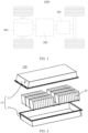


Classifications
-
- H—ELECTRICITY
- H01—ELECTRIC ELEMENTS
- H01M—PROCESSES OR MEANS, e.g. BATTERIES, FOR THE DIRECT CONVERSION OF CHEMICAL ENERGY INTO ELECTRICAL ENERGY
- H01M10/00—Secondary cells; Manufacture thereof
- H01M10/04—Construction or manufacture in general
-
- H—ELECTRICITY
- H01—ELECTRIC ELEMENTS
- H01M—PROCESSES OR MEANS, e.g. BATTERIES, FOR THE DIRECT CONVERSION OF CHEMICAL ENERGY INTO ELECTRICAL ENERGY
- H01M10/00—Secondary cells; Manufacture thereof
- H01M10/42—Methods or arrangements for servicing or maintenance of secondary cells or secondary half-cells
- H01M10/4235—Safety or regulating additives or arrangements in electrodes, separators or electrolyte
-
- H—ELECTRICITY
- H01—ELECTRIC ELEMENTS
- H01M—PROCESSES OR MEANS, e.g. BATTERIES, FOR THE DIRECT CONVERSION OF CHEMICAL ENERGY INTO ELECTRICAL ENERGY
- H01M10/00—Secondary cells; Manufacture thereof
- H01M10/42—Methods or arrangements for servicing or maintenance of secondary cells or secondary half-cells
- H01M10/4242—Regeneration of electrolyte or reactants
-
- H—ELECTRICITY
- H01—ELECTRIC ELEMENTS
- H01M—PROCESSES OR MEANS, e.g. BATTERIES, FOR THE DIRECT CONVERSION OF CHEMICAL ENERGY INTO ELECTRICAL ENERGY
- H01M10/00—Secondary cells; Manufacture thereof
- H01M10/42—Methods or arrangements for servicing or maintenance of secondary cells or secondary half-cells
- H01M10/52—Removing gases inside the secondary cell, e.g. by absorption
-
- H—ELECTRICITY
- H01—ELECTRIC ELEMENTS
- H01M—PROCESSES OR MEANS, e.g. BATTERIES, FOR THE DIRECT CONVERSION OF CHEMICAL ENERGY INTO ELECTRICAL ENERGY
- H01M50/00—Constructional details or processes of manufacture of the non-active parts of electrochemical cells other than fuel cells, e.g. hybrid cells
- H01M50/10—Primary casings; Jackets or wrappings
- H01M50/14—Primary casings; Jackets or wrappings for protecting against damage caused by external factors
- H01M50/143—Fireproof; Explosion-proof
-
- H—ELECTRICITY
- H01—ELECTRIC ELEMENTS
- H01M—PROCESSES OR MEANS, e.g. BATTERIES, FOR THE DIRECT CONVERSION OF CHEMICAL ENERGY INTO ELECTRICAL ENERGY
- H01M50/00—Constructional details or processes of manufacture of the non-active parts of electrochemical cells other than fuel cells, e.g. hybrid cells
- H01M50/30—Arrangements for facilitating escape of gases
- H01M50/317—Re-sealable arrangements
-
- H—ELECTRICITY
- H01—ELECTRIC ELEMENTS
- H01M—PROCESSES OR MEANS, e.g. BATTERIES, FOR THE DIRECT CONVERSION OF CHEMICAL ENERGY INTO ELECTRICAL ENERGY
- H01M50/00—Constructional details or processes of manufacture of the non-active parts of electrochemical cells other than fuel cells, e.g. hybrid cells
- H01M50/30—Arrangements for facilitating escape of gases
- H01M50/342—Non-re-sealable arrangements
- H01M50/3425—Non-re-sealable arrangements in the form of rupturable membranes or weakened parts, e.g. pierced with the aid of a sharp member
-
- H—ELECTRICITY
- H01—ELECTRIC ELEMENTS
- H01M—PROCESSES OR MEANS, e.g. BATTERIES, FOR THE DIRECT CONVERSION OF CHEMICAL ENERGY INTO ELECTRICAL ENERGY
- H01M50/00—Constructional details or processes of manufacture of the non-active parts of electrochemical cells other than fuel cells, e.g. hybrid cells
- H01M50/30—Arrangements for facilitating escape of gases
- H01M50/383—Flame arresting or ignition-preventing means
-
- H—ELECTRICITY
- H01—ELECTRIC ELEMENTS
- H01M—PROCESSES OR MEANS, e.g. BATTERIES, FOR THE DIRECT CONVERSION OF CHEMICAL ENERGY INTO ELECTRICAL ENERGY
- H01M50/00—Constructional details or processes of manufacture of the non-active parts of electrochemical cells other than fuel cells, e.g. hybrid cells
- H01M50/60—Arrangements or processes for filling or topping-up with liquids; Arrangements or processes for draining liquids from casings
- H01M50/609—Arrangements or processes for filling with liquid, e.g. electrolytes
- H01M50/618—Pressure control
-
- H—ELECTRICITY
- H01—ELECTRIC ELEMENTS
- H01M—PROCESSES OR MEANS, e.g. BATTERIES, FOR THE DIRECT CONVERSION OF CHEMICAL ENERGY INTO ELECTRICAL ENERGY
- H01M50/00—Constructional details or processes of manufacture of the non-active parts of electrochemical cells other than fuel cells, e.g. hybrid cells
- H01M50/60—Arrangements or processes for filling or topping-up with liquids; Arrangements or processes for draining liquids from casings
- H01M50/673—Containers for storing liquids; Delivery conduits therefor
- H01M50/682—Containers for storing liquids; Delivery conduits therefor accommodated in battery or cell casings
-
- H—ELECTRICITY
- H01—ELECTRIC ELEMENTS
- H01M—PROCESSES OR MEANS, e.g. BATTERIES, FOR THE DIRECT CONVERSION OF CHEMICAL ENERGY INTO ELECTRICAL ENERGY
- H01M2200/00—Safety devices for primary or secondary batteries
-
- H—ELECTRICITY
- H01—ELECTRIC ELEMENTS
- H01M—PROCESSES OR MEANS, e.g. BATTERIES, FOR THE DIRECT CONVERSION OF CHEMICAL ENERGY INTO ELECTRICAL ENERGY
- H01M2220/00—Batteries for particular applications
- H01M2220/20—Batteries in motive systems, e.g. vehicle, ship, plane
-
- Y—GENERAL TAGGING OF NEW TECHNOLOGICAL DEVELOPMENTS; GENERAL TAGGING OF CROSS-SECTIONAL TECHNOLOGIES SPANNING OVER SEVERAL SECTIONS OF THE IPC; TECHNICAL SUBJECTS COVERED BY FORMER USPC CROSS-REFERENCE ART COLLECTIONS [XRACs] AND DIGESTS
- Y02—TECHNOLOGIES OR APPLICATIONS FOR MITIGATION OR ADAPTATION AGAINST CLIMATE CHANGE
- Y02E—REDUCTION OF GREENHOUSE GAS [GHG] EMISSIONS, RELATED TO ENERGY GENERATION, TRANSMISSION OR DISTRIBUTION
- Y02E60/00—Enabling technologies; Technologies with a potential or indirect contribution to GHG emissions mitigation
- Y02E60/10—Energy storage using batteries
Definitions
- This application relates to the field of batteries, and in particular, to a tank, a battery cell, a battery, and an electrical device.
- Electric vehicles have become an important part of the sustainable development of the automobile industry by virtue of energy saving and environmental friendliness. Battery technology is crucial to development of electric vehicles.
- Embodiments of this application provide a tank, a battery cell, a battery, and an electrical device to enhance battery safety.
- an embodiment of this application discloses a tank.
- a plurality of independent accommodation cavities are arranged in the tank.
- Each of the accommodation cavities includes a corresponding fragile structure.
- Each fragile structure possesses a different packaging strength.
- This embodiment of this application implements the function of storing different types of filling substances by using a single tank.
- the different filling substances stored in the accommodation cavities in the tank can be released stepwise in response to different external pressures. Therefore, the electrode assembly at different stages can be refilled with different dosages of electrolyte or different types of desired substances depending on the internal pressure of the battery cell, thereby improving pertinency of refilling the electrode assembly with desired substances.
- one or more sub-tanks are arranged inside the tank.
- the tank and the sub-tanks are nested with each other to form independent accommodation cavities. Packaging strengths of the corresponding fragile structures of the accommodation cavities increase progressively from outward to inward.
- the multi-layer nested parent-child tank disclosed in this embodiment of this application is simple in structure and implements the function of storing different types of filling substances by using a single tank.
- the different filling substances stored in the accommodation cavities in the tank can be released stepwise in response to different external pressures.
- a membrane is arranged in the tank.
- the membrane is configured to partition an interior of the tank into a plurality of independent accommodation cavities.
- the fragile structure is arranged at a position located on a surface of the tank and corresponding to each accommodation cavity. Each fragile structure possesses a different packaging strength.
- the twin tank structure disclosed in this embodiment of this application is simple in structure and implements the function of storing different types of filling substances by using a single tank.
- the different filling substances stored in the accommodation cavities in the tank can be released stepwise.
- an embodiment of this application discloses a battery cell, including: a housing; an electrode assembly, accommodated in the housing; and the tank disclosed in the foregoing embodiment, where the tank is accommodated in the housing, and is arranged corresponding to a sidewall of the electrode assembly.
- This embodiment of this application implements the function of storing different types of filling substances by using a single tank.
- the different filling substances stored in the accommodation cavities in the tank can be released stepwise in response to different external pressures, thereby improving pertinency of refilling the electrode assembly with the desired substances.
- the electrode assembly can be refilled with substances precisely and meticulously.
- the fragile structure is arranged corresponding to the sidewall of the electrode assembly.
- the filling substance can contact the sidewall of the electrode assembly first, thereby improving the effect of infiltration.
- a plurality of electrode assemblies are included.
- the tank is arranged between each electrode assembly and a sidewall of the housing, and/or the tank is arranged between adjacent electrode assemblies.
- this embodiment of this application arranges a tank structure between different electrode assemblies.
- the gas pressure in the battery cell is excessive, or the electrode assembly expands during use, in a case that the expansion force is greater than a pressure threshold tolerable by the fragile structure of the tank, the tank arranged between the electrode assemblies is ruptured, and the overflowing substance directly contacts the electrode assembly, so that the electrode assembly can absorb the desired substance more efficiently.
- the tank includes a plurality of fragile structures.
- the plurality of fragile structures are arranged corresponding to sidewalls of the electrode assembly respectively.
- the tank can release the filling substance from the plurality of fragile structures simultaneously.
- a plurality of parts of the electrode assembly can contact the filling substance simultaneously, thereby improving the effect of infiltration for the electrode assembly, and making the electrode assembly absorb the desired filling substance more efficiently.
- an explosion-proof valve is arranged on the housing, and the tank is arranged opposite to the explosion-proof valve.
- the filling substance stored in the tank can be released more efficiently.
- each fragile structure possesses a different packaging thickness.
- the corresponding fragile structure of each accommodation cavity possesses a different packaging strength.
- the filling substance in the accommodation cavity corresponding to the fragile structure with the lowest packaging strength is released first.
- the filling substances in the accommodation cavities corresponding to the fragile structures with relatively high packaging strengths are released stepwise when the gas pressure in the battery cell increases gradually.
- packaging strengths of the fragile structures change stepwise.
- the packaging strengths of the corresponding fragile structures of the accommodation cavities are set to change stepwise to gradually release the substances required by the electrode assembly.
- each accommodation cavity stores a different substance.
- the accommodation cavities store a flame retardant, a gas absorbent, a lithium supplementing agent, and an electrolytic solution respectively in descending order of the packaging strength of the fragile structure.
- the electrode assembly is provided with various desired substances more pertinently, thereby achieving the purposes such as improving the lifespan of the electrode assembly and the safety of the electrode assembly.
- an embodiment of this application discloses a battery cell, including: a housing; an electrode assembly, accommodated in the housing; and a plurality of tanks, accommodated in the housing, and arranged corresponding to sidewalls of the electrode assembly respectively, where a fragile structure is arranged on a surface of each of the tanks, and the fragile structure of each tank possesses a different packaging strength.
- a plurality of discrete tanks with fragile structures of different packaging strengths are arranged in the battery cell, so that different discrete tanks can release different filling substances stepwise in sequence under different pressures.
- the fragile structure is arranged corresponding to the sidewall of the electrode assembly.
- the filling substance can contact the sidewall of the electrode assembly first, thereby improving the effect of infiltration.
- a plurality of electrode assemblies are included.
- the tank is arranged between each electrode assembly and a sidewall of the housing, and/or the tank is arranged between adjacent electrode assemblies.
- this embodiment of this application arranges a tank structure between different electrode assemblies.
- the gas pressure in the battery cell is excessive, or the electrode assembly expands during use, in a case that the expansion force is greater than a pressure threshold tolerable by the fragile structure of the tank, the tank arranged between the electrode assemblies is ruptured, and the overflowing substance directly contacts the electrode assembly, so that the electrode assembly can absorb the desired substance more efficiently.
- the tank includes a plurality of fragile structures.
- the plurality of fragile structures are arranged corresponding to sidewalls of the electrode assembly respectively.
- the tank can release the filling substance from the plurality of fragile structures simultaneously.
- a plurality of parts of the electrode assembly can contact the filling substance simultaneously, thereby improving the effect of infiltration for the electrode assembly, and making the electrode assembly absorb the desired filling substance more efficiently.
- the fragile structure of each tank possesses a different packaging thickness.
- the corresponding fragile structure of each accommodation cavity possesses a different packaging strength.
- the filling substance in the accommodation cavity corresponding to the fragile structure with the lowest packaging strength is released first.
- the filling substances in the accommodation cavities corresponding to the fragile structures with relatively high packaging strengths are released stepwise when the gas pressure in the battery cell increases gradually.
- packaging strengths of the fragile structures of the tanks change stepwise.
- the packaging strengths of the corresponding fragile structures of the accommodation cavities are set to change stepwise to gradually release the substances required by the electrode assembly.
- an embodiment of this application discloses a battery, including the battery cell according to the foregoing embodiment.
- an embodiment of this application discloses an electrical device.
- the electrical device includes the battery disclosed in the foregoing embodiment, and the battery is configured to provide electrical energy.
- a “connection” may be a fixed connection, a detachable connection, or an integrated connection; or may be a direct connection or an indirect connection implemented through an intermediary; or may be internal communication between two components.
- a plurality of referred to in this application means two or more (including two).
- a plurality of groups means two or more groups (including two groups)
- a plurality of pieces means two or more pieces (including two pieces).
- a battery cell may include a lithium-ion secondary battery, a lithium-ion primary battery, a lithium-sulfur battery, a sodium-lithium-ion battery, a sodium-ion battery, a magnesium-ion battery, or the like, without being limited in embodiments of this application.
- the battery cell may be in a cylindrical shape, a flat shape, a cuboidal shape, or other shapes, without being limited in embodiments of this application.
- the battery cell is typically classed into three types: cylindrical battery cell, prismatic battery cell, and pouch-type battery cell, without being limited in embodiments of this application.
- Power batteries are not only used in energy storage power systems such as hydro, thermal, wind, and solar power stations, but also widely used in electric means of transport such as electric bicycles, electric motorcycles, and electric vehicles, and used in many other fields such as military equipment and aerospace.
- electric means of transport such as electric bicycles, electric motorcycles, and electric vehicles, and used in many other fields such as military equipment and aerospace.
- the market demand for power batteries keeps expanding with the widening of the fields to which the power batteries are applicable.
- ions are intercalated into or deintercalated from a positive active material and a negative active material during charge-and-discharge cycles of a battery, resulting in expansion inside an electrode assembly.
- An electrolytic solution inside the electrode assembly decreases gradually, resulting in electrolyte shortage inside the electrode assembly and lack of active lithium components.
- the problem of metal dissolution gradually occurs. In severer cases, thermal runaway may occur, and the battery is prone to fire or explosion. The resulting safety problems are nonnegligible.
- an electrolyte refilling mechanism is usually arranged in a battery cell.
- the electrolyte refilling mechanism contains an electrolytic solution.
- the electrolyte refilling mechanism ruptures, and releases and provides pre-stored electrolytic solution to the electrode assembly, so as to make up for the electrolytic solution that is lacking due to the increased charge-and-discharge cycles or aging of the electrode assembly.
- the inventor of this application finds that the amount of the electrolytic solution that is lacking varies depending on how long the electrode assembly has been used. For example, after the electrode assembly has just been used for a short duration, just a small amount of electrolytic solution is lacking. With the increase of the duration of being used, the amount of electrolytic solution that is lacking increases gradually. Therefore, the electrode assembly at different stages needs to be refilled with different dosages of electrolytic solution. In addition, the electrolyte shortage inside the electrode assembly leads to different hazards in different stages of the electrode assembly. Electrolyte refilling alone is unable to solve the problems arising in the long-term use of the electrode assembly. Currently, no solutions are available to pertinently refilling the battery cell with the substance that is lacking, and to resolving hazards at different stages. Refined solutions are lacking.
- the inventor of this application has carried out in-depth research and designed a novel tank, battery cell, and electrical device.
- a plurality of independent accommodation cavities are arranged inside the tank, and each accommodation cavity includes fragile structures that differ in packaging strength. Therefore, the same substance or different substances in the electrode assembly can be released gradually in view of a pressure inside the electrode assembly that is in use or in different aging states.
- the tank and the battery cell disclosed in embodiments of this application are applicable to, but without being limited to, electrical devices such as a vehicle, watercraft, or aircraft.
- a power supply system of the electrical device may include the tank, the battery cell, and the like disclosed in this application to help alleviate the problems such as lack of substances and degradation of safety of the electrode assembly in use, and improve performance stability and longevity of the battery.
- An embodiment of this application provides an electrical device powered by a battery.
- the electrical device may be, but without being limited to, a mobile phone, a tablet, a notebook computer, an electric toy, an electric tool, an electric power cart, an electric vehicle, a ship, a spacecraft, and the like.
- the electric toy may include stationary or mobile electric toys, such as a game console, an electric car toy, an electric ship toy, an electric airplane toy, and the like.
- the spacecraft may include an airplane, a rocket, a space shuttle, a spaceship, and the like.
- a vehicle 1000 is used as an example of the electrical device according to an embodiment of this application.
- FIG. 1 is a schematic structural diagram of a vehicle 1000 according to an embodiment of this application.
- the vehicle 1000 may be an oil-fueled vehicle, a natural gas vehicle, or a new energy vehicle.
- the new energy vehicle may be a battery electric vehicle, a hybrid electric vehicle, a range-extended electric vehicle, or the like.
- a battery 100 is disposed inside the vehicle 1000.
- the battery 100 may be disposed at the bottom, front, or rear of the vehicle 1000.
- the battery 100 may be configured to supply power to the vehicle 1000.
- the battery 100 may serve as an operating power supply of the vehicle 1000.
- the vehicle 1000 may further include a controller 200 and a motor 300.
- the controller 200 is configured to control the battery 100 to supply power to the motor 300, for example, to start or navigate the vehicle 1000, or meet the operating power requirements of the vehicle in operation.
- the battery 100 serves not only as an operating power supply of the vehicle 1000, but may also serve as a drive power supply of the vehicle 1000 to provide driving power for the vehicle 1000 in place of or partially in place of oil or natural gas.
- FIG. 2 is an exploded view of a battery 100 according to an embodiment of this application.
- the battery 100 includes a box 10 and a battery cell 20.
- the battery cell 20 is accommodated in the box 10.
- the box 10 is configured to provide an accommodation space for the battery cell 20.
- the box 10 may be variously structured.
- the box 10 may include an upper box 11 and a lower box 12.
- the upper box 11 and the lower box 12 fit and cover each other.
- the upper box 11 and the lower box 12 together define an accommodation space configured to accommodate the battery cell 20.
- the lower box 12 may be a hollow structure opened at one end.
- the upper box 11 may be a plate-like structure.
- the upper box 11 fits an opening end of the lower box 12 so that the upper box 11 and the lower box 12 together define the accommodation space.
- both the upper box 11 and the lower box 12 may be hollow structures opened at one end.
- the opening end of the upper box 11 fits the opening end of the lower box 12.
- the box 10 formed by the upper box 11 and the lower box 12 may be in various shapes, such as a cylinder or a cuboid.
- the battery 100 referred to in this embodiment of this application means a stand-alone physical module that includes one or more battery cells to provide a higher voltage and a higher capacity.
- the battery 100 referred to in this application may include a battery module, a battery pack, and the like.
- the series-and-parallel pattern means a combination of series connection and parallel connection of the plurality of battery cells 20.
- the plurality of battery cells 20 may be directly connected in series, parallel, or series-and-parallel pattern, and then the whole of the plurality of battery cells 20 may be accommodated in the box 10.
- the plurality of battery cells 20 may be connected in series, parallel, or series-and-parallel pattern to form a battery 100 in the form of battery modules first. A plurality of battery modules are then connected in series, parallel, or series-and-parallel pattern to form a whole for being accommodated in the box 10.
- the battery 100 may further include other structures.
- the battery 100 may further include a busbar component. The busbar component is configured to implement electrical connection between the plurality of battery cells 20.
- Each battery cell 20 may be, but is not limited to, a lithium-ion secondary battery, a lithium-ion primary battery, a lithium-sulfur battery, a sodium-lithium-ion battery, or a magnesium-ion battery.
- the battery cell 20 may be in a cylindrical shape, a flat shape, a cuboidal shape, or other shapes.
- the battery cell 20 includes a housing 210, electrodes 220, and an electrode assembly 240.
- the electrode assembly 240 is located in the housing 210, and is connected to the electrodes 220 and configured to output electrical energy outward.
- the housing 210 is a component configured to form an internal environment of the battery cell.
- the formed internal environment may be used to accommodate the electrode assembly, an electrolytic solution, and other components.
- the electrodes 220 are led out of the housing 210.
- the electrodes includes a positive electrode and a negative electrode.
- the positive electrode and the negative electrode are connected to a positive tab and a negative tab of the electrode assembly respectively by an adapter.
- the housing may be shaped and sized variously, for example, cuboidal, cylindrical, or hexagonal prismatic. Specifically, the shape of the housing may be determined depending on the specific shape and size of an electrode assembly.
- the housing may be made of a variety of materials such as copper, iron, aluminum, stainless steel, aluminum alloy, or plastic, without being particularly limited herein.
- an explosion-proof valve 230 is arranged between electrodes on the housing. When the gas pressure in the battery cell reaches a given value, the pressure can be released through the explosion-proof valve to avoid safety problems such as explosion of the battery cell.
- the electrode assembly 240 is a component that reacts electrochemically in the battery cell 20.
- the housing may contain one or more electrode assemblies.
- the electrode assembly is primarily formed by winding or stacking a positive electrode plate and a negative electrode plate, and a separator is generally arranged between the positive electrode plate and the negative electrode plate.
- the parts, coated with an active material, of the positive electrode plate and the negative electrode plate, constitute a body portion of the electrode assembly.
- the parts, coated with no active material, of the positive electrode plate and the negative electrode plate constitutes a positive tab and a negative tab, respectively.
- the positive tab and the negative tab may be located at one end of the body portion together or at two ends of the body portion respectively.
- the positive active material and the negative active material react with an electrolytic solution.
- the tabs are connected to electrode terminals to form a current circuit.
- the positive tab is connected to the positive electrode on the housing by an adapter, and the negative tab is connected to the negative electrode on the housing by an adapter.
- one or more tanks 40 are arranged between the electrode assembly 240 and the housing 210.
- the tanks 40 contain rapidly consumed substances such as electrolytic solution of the electrode assembly.
- the pressure acts on the tanks to crush the tanks, thereby releasing the electrolytic solution out of the tanks to supplement the electrolytic solution of the electrode assembly, thereby alleviating the problems such as performance deterioration caused by electrolyte shortage after long-term use of the battery.
- the tank according to this embodiment of this application is applied to the foregoing battery cell.
- the tank according to this application can release the same substance or different substances gradually in view of a pressure inside the electrode assembly that is in use or in different aging states.
- different dosages of electrolytic solution or different types of desired substances are provided, thereby solving the problems such as lack of substances and deterioration of safety performance of the battery cell in use.
- FIG. 4 to FIG. 7 the tank according to this embodiment of this application is shown in FIG. 4 to FIG. 7 .
- a plurality of independent accommodation cavities are arranged in the tank according to this embodiment of this application.
- Each of the accommodation cavities includes a corresponding fragile structure.
- Each fragile structure possesses a different packaging strength.
- the tank is usually a capsule-shaped or otherwise shaped object made of a flexible material and capable of accommodating and storing liquid, inert gas, or other forms of substances. Understandably, the tank is not necessarily capsule-shaped, but may be made in any shape that meets requirements of the application environment, for example, may be square, round, oval, or irregularly shaped.
- the flexible material may be formed by stamping an aluminum sheet and then sputtering an inert material onto the surface of the stamped aluminum sheet, where the inert material is a high-molecular polymer such as PP, PE, PET, or PVC.
- the tank may be made of other materials of specified flexibility and hardness.
- a plurality of independent accommodation cavities may be arranged in the tank in the way shown in FIG. 4 or FIG. 6 .
- Identical or different tank materials may be used to partition the interior space of the tank into a plurality of independent closed spaces.
- the closed spaces form independent accommodation cavities.
- the accommodation cavities are configured to hold liquid or inert gas. With the independent accommodation cavities arranged, different liquids or inert gases can be separated from each other, so as to release different substances pertinently.
- Each accommodation cavity is formed by being surrounded by the flexible material.
- a fragile structure is arranged on an outer wall of each accommodation cavity enclosed with the corresponding flexible material. That is, each accommodation cavity formed in the tank corresponds to a fragile structure separately. In this way, the liquid or inert gas stored in each accommodation cavity can be released through the corresponding fragile structure without affecting the filling substance stored in other accommodation cavities.
- this application assigns a different packaging strength to the fragile structure corresponding to each different accommodation cavity.
- the filling substance in the accommodation cavity corresponding to the fragile structure with the lowest packaging strength is released first.
- the filling substances in the accommodation cavities corresponding to the fragile structures with relatively high packaging strengths are released stepwise when the gas pressure in the battery cell increases gradually.
- the packaging strength of the fragile structure may be formed by making a fragile region in a given part of the flexible material in a way such as reducing the thickness of the given part by laser etching, acid etching of aluminum, or die-cut mold scratching of aluminum.
- the proportion of the fragile region in the area of the entire outer wall of the tank is approximately 10% to 50%.
- the thickness of the fragile region is generally 10 ⁇ m to 300 ⁇ m.
- the pressure borne by the fragile region is less than that borne by other non-thinned regions.
- the thickness may differ between the fragile regions depending on the required packaging strength.
- the pressure threshold borne by the fragile region is positively correlated with the thickness (for example, the internal pressure threshold is 0.25 MPa when the thickness of the fragile region is 100 ⁇ m, and the internal pressure threshold is 0.4 MPa when the thickness is 200 ⁇ m). Therefore, each capsule can regulate the pressure relief order by using stepwise thicknesses of the fragile regions.
- the fragile regions may be formed by nicking a given part of the outer wall of the tank. The depth of the nick represents the packaging strength of the fragile region. A great depth represents a lower packaging strength, and a small depth represents a higher packaging strength.
- each accommodation cavity includes a corresponding fragile structure, and each fragile structure possesses a different packaging strength.
- this embodiment implements the function of storing different types of filling substances by using a single tank.
- the different filling substances stored in the accommodation cavities in the tank can be released stepwise in response to different external pressures. Therefore, the electrode assembly at different stages can be refilled with different dosages of electrolytic solution or different types of desired substances depending on the internal pressure of the battery cell, thereby improving pertinency of refilling the electrode assembly with the desired substances.
- FIG. 4 shows a parent-child tank structure.
- One or more sub-tanks are arranged inside the tank.
- the tank and the sub-tanks are nested with each other to form independent accommodation cavities.
- Packaging strengths of the corresponding fragile structures of the accommodation cavities increase progressively from outward to inward.
- FIG. 5 shows effects after the parent-child tank structure is filled with different substances.
- the parent-child tank structure 50 includes a first accommodation cavity 510, a second accommodation cavity 520, and a third accommodation cavity 530.
- the first accommodation cavity 510 is formed by being enclosed with a first tank wall 511 and a first fragile structure 512.
- a sub-tank is arranged inside the first accommodation cavity 510.
- the sub-tank includes a second accommodation cavity 520.
- the second accommodation cavity 520 is formed by being enclosed with a second tank wall 521 and a second fragile structure 522.
- a sub-tank is further arranged inside the second accommodation cavity 520.
- the sub-tank includes a third accommodation cavity 530.
- the third accommodation cavity 530 is formed by being enclosed with a third tank wall 531 and a third fragile structure 532.
- the outermost tank forms a parent tank of the parent-child tank structure, and two sub-tanks are formed inside the parent tank.
- the tank and the sub-tanks are nested with each other to form independent accommodation cavities.
- Tanks are further nested inside a tank to form hierarchical nesting.
- the innermost sub-tank is formed first. After the third filling substance 533 is injected into the third accommodation cavity 530, the third accommodation cavity is sealed by laser welding or other means. At the same time, the third fragile structure 532 is formed on the third tank wall 531. Subsequently, the sub-tank is wrapped in a flexible material to form a parent tank of the sub-tank. The second accommodation cavity 520 is formed between the sub-tank and the parent tank. After the second filling substance 523 is injected into the second accommodation cavity 520, the second accommodation cavity is sealed by laser welding or other means. At the same time, the second fragile structure 522 is formed on the second tank wall 521.
- the second sub-tank is further wrapped in a flexible material to form a parent tank of the second sub-tank.
- the first accommodation cavity 510 is formed between the sub-tank and the parent tank.
- the first accommodation cavity is sealed by laser welding or other means.
- the first fragile structure 512 is formed on the first tank wall 511. It needs to be noted that FIG. 4 merely shows a structure in which three independent accommodation cavities are arranged inside the parent-child tank. Fewer or more sub-tanks may be arranged as required, details of which are omitted here.
- the packaging strengths of the fragile structures increase progressively in order from outside to inside of the parent-child tank structure.
- the first fragile structure 512 is located on the surface of an outermost tank, and possesses the lowest packaging strength, and ruptures first when receiving an internal pressure of the battery cell.
- the packaging strength of the second fragile structure 522 is higher than the packaging strength of the first fragile structure, and the packaging strength of the third fragile structure 532 is the highest.
- the fragile structures of the parent-child tank are ruptured in sequence from outside to inside to release the first filling substance 513, the second filling substance 523, and the third filling substance 533 in sequence.
- the parent-child tank structure is nested hierarchically.
- a plurality of independent accommodation cavities are arranged, each accommodation cavity includes a corresponding fragile structure, and each fragile structure possesses a different packaging strength.
- this embodiment implements the function of storing different types of filling substances by using a single tank.
- the different filling substances stored in the accommodation cavities in the tank can be released stepwise in response to different external pressures, thereby improving pertinency of refilling the electrode assembly with the desired substances.
- FIG. 6 another twin tank structure 60 is provided.
- a membrane is arranged in the twin tank.
- the membrane is configured to partition the interior of the tank into a plurality of independent accommodation cavities.
- the fragile structure is arranged at a position located on a surface of the tank and corresponding to each accommodation cavity. Each fragile structure possesses a different packaging strength.
- FIG. 7 is a schematic diagram of the twin tank filled with different substances.
- a first accommodation cavity 610, a second accommodation cavity 620, and a third accommodation cavity 630 are arranged in the twin tank 60.
- the first accommodation cavity 610 is isolated from the second accommodation cavity 620 by a first membrane 614.
- the second accommodation cavity 620 is isolated from the third accommodation cavity 630 by a second membrane 624, so that the accommodation cavities are independent of each other.
- the first accommodation cavity 610 is formed by being enclosed with a first tank wall 611, a first fragile structure 612, and a first membrane 614.
- the first tank wall 611 and the first fragile structure are located outside the twin tank 60, and exposed outside.
- the first membrane 614 is located inside the twin tank 60, and isolates the first accommodation cavity 610 from the second accommodation cavity 620 to make the two accommodation cavities independent of each other.
- the first membrane 614 may be made of the same material as the first tank wall, or made of a different material.
- the first fragile structure 612 is arranged on a tank wall corresponding to the first accommodation cavity 610. When the first fragile structure 612 is ruptured, the filling substance in the first accommodation cavity 610 is released.
- the second accommodation cavity 620 is formed by being enclosed with a second tank wall 621, a second fragile structure 622, the first membrane 614, and a second membrane 624.
- the second tank wall 621 and the second fragile structure 622 are located outside the twin tank 60, and integrated with the tank outer wall corresponding to the first accommodation cavity.
- the second membrane 624 is located inside the twin tank 60, and works together with the first membrane 614 to partition the interior space of the twin tank 60 to form an independent second accommodation cavity 620.
- the second membrane 624 may be made of the same material as the second tank wall, or made of a different material.
- the second fragile structure 622 is arranged on a tank wall corresponding to the second accommodation cavity 620. When the second fragile structure 622 is ruptured, the filling substance in the second accommodation cavity 620 is released.
- the third accommodation cavity 630 is formed by being enclosed with a third tank wall 631, a third fragile structure 632, and the second membrane 624.
- the third tank wall 631 and the third fragile structure 632 are located outside the twin tank, and connected to the tank outer wall corresponding to the second accommodation cavity 620.
- the second membrane 624 is located inside the twin tank 60, and partitions the interior space of the twin tank 60 into a second accommodation cavity 620 and a third accommodation cavity 630.
- the third fragile structure 632 is arranged on a tank wall corresponding to the third accommodation cavity 630. When the third fragile structure 632 is ruptured, the filling substance in the third accommodation cavity 630 is released.
- the first membrane 610 and the second membrane 620 are arranged to partition the interior space of the twin tank 60 into three independent accommodation cavities.
- the three independent accommodation cavities correspond to separate fragile structures respectively.
- the corresponding fragile structure of each accommodation cavity possesses a different packaging strength.
- the packaging strength of the first fragile structure 612 is greater than the packaging strength of the second fragile structure 622
- the packaging strength of the second fragile structure 622 is greater than the packaging strength of the third fragile structure 632.
- the filling substances in the accommodation cavities corresponding to the fragile structures with relatively high packaging strengths are released stepwise when the gas pressure in the battery cell increases gradually.
- the filling substance in the third accommodation cavity 630 is released first, the filling substance in the second accommodation cavity 620 is released later, and the filling substance in the first accommodation cavity 610 is released last.
- the packaging strength of the fragile structure may be formed by making a fragile region in a given part of the flexible material in a way such as reducing the thickness of the given part by laser etching, acid etching of aluminum, or die-cut mold scratching of aluminum.
- the proportion of the fragile region in the area of the entire outer wall of the tank is approximately 10% to 50%.
- the thickness of the fragile region is generally 10 ⁇ m to 300 ⁇ m.
- the pressure borne by the fragile region is less than that borne by other non-thinned regions.
- the thickness may differ between the fragile regions depending on the required packaging strength.
- the pressure threshold borne by the fragile region is positively correlated with the thickness (for example, the internal pressure threshold is 0.25 MPa when the thickness of the fragile region is 100 ⁇ m, and the internal pressure threshold is 0.4 MPa when the thickness is 200 ⁇ m). Therefore, each capsule can regulate the pressure relief order by using stepwise thicknesses of the fragile regions.
- the fragile regions may be arranged in various ways. Another way of forming the fragile regions is to nick a given part of the outer wall of the tank. The depth of the nick represents the packaging strength of the fragile region. The packaging strength is lower if the depth is great, and the packaging strength is higher if the depth is small.
- first, the first membrane 614 and the second membrane 62 are arranged inside the tank wall by welding or gluing or other means.
- the first membrane 614, the second membrane 62, and the outer wall of the tank form an accommodation cavity.
- the accommodation cavity is sealed by laser welding or other means, thereby forming a twin tank structure.
- FIG. 7 is a schematic diagram of a twin tank 60 after independent accommodation cavities in the twin tank are filled with filling substances.
- the first accommodation cavity 610 is filled with a first filling substance 613
- the second accommodation cavity 620 is filled with a second filling substance 623
- the third accommodation cavity 630 is filled with a third filling substance 633.
- the filling substances may be the same or different. When the filling substances are the same, the same substance can be released in an orderly manner under different pressures in the battery cell. When the filling substances are different, different substances can be released in an orderly manner under different pressures in the battery cell to refill the battery cell with various desired substances.
- the packaging strengths of the fragile structures may be set at discretion.
- the number of independent accommodation cavities in the twin tank is relatively large, for example, is 5 to 9
- the fragile structures corresponding to two or three accommodation cavities may be set to possess the same packaging strength, so as to increase the dosage of a substance released at a time.
- the difference in the packaging strength between the fragile structures may be reduced, so as to reduce intervals at which different accommodation cavities release the filling substance, and to refill the electrode assembly with the desired substance stepwise at dense intervals.
- the capacity may be identical or different between the accommodation cavities.
- the capacity of each accommodation cavity may be set at discretion according to the use characteristics of the electrode assembly.
- the substance consumed by the electrode assembly in a large amount may be stored in a large-capacity accommodation cavity, and the substance consumed in a small amount may be stored in a small-capacity accommodation cavity.
- other arrangement manners are applicable, without being limited in this embodiment of this application.
- the membrane partitions the interior space of the tank into a plurality of independent accommodation cavities.
- Each accommodation cavity includes a corresponding fragile structure, and each fragile structure possesses a different packaging strength.
- this embodiment implements the function of storing different types of filling substances by using a single tank.
- the different filling substances stored in the accommodation cavities in the tank can be released stepwise in response to different external pressures, thereby improving pertinency of refilling the electrode assembly with the desired substances.
- the battery cell includes a housing 210, an electrode assembly 240, and the parent-child tank 50 and/or the twin tank 60 disclosed in the foregoing embodiments.
- the electrode assembly 240 is accommodated in the housing 210.
- the parent-child tank 50 and/or the twin tank 60 is accommodated in the housing, and arranged corresponding to a sidewall of the electrode assembly 240.
- the battery cell 20 includes one or more parent-child tanks 50.
- the structures of the parent-child tanks 50 are illustrated in FIG. 4 and FIG. 5 , description of which is omitted here.
- the parent-child tank is arranged corresponding to a sidewall of the electrode assembly 240.
- the sidewall of the electrode assembly includes a sidewall of the electrode assembly in a height direction, a sidewall in a width direction, a sidewall of the electrode assembly in a thickness direction, and the like.
- the first parent-child tank 501 and the second parent-child tank 502 are arranged between a sidewall of the electrode assembly in the height direction and the housing.
- the parent-child tank may be arranged on the housing by gluing or laser welding or other means, or arranged on the electrode assembly. Alternatively, the parent-child tank may be placed in all gaps between the sidewall and the housing, so as to fill all spaces.
- the third parent-child tank 503 is arranged corresponding to a sidewall of the electrode assembly in the height direction, and located at the bottom of the housing of the battery cell.
- the fourth parent-child tank 504 is arranged corresponding to a sidewall at the other end of the electrode assembly in the height direction, and located on the top of the electrode assembly.
- the battery cell 20 includes one or more twin tanks 60.
- the structures of the twin tanks 60 are illustrated in FIG. 6 and FIG. 7 , description of which is omitted here.
- the twin tank is arranged corresponding to a sidewall of the electrode assembly 240.
- the sidewall of the electrode assembly includes a sidewall of the electrode assembly in the height direction, a sidewall in a width direction, a sidewall of the electrode assembly in a thickness direction, and the like.
- the twin tank may be arranged in any interspace inside the electrode assembly, including any interspace on two sides of or above the electrode assembly or other spaces, without limiting the number and shape of the tanks.
- the first twin tank 601 and the second twin tank 602 are arranged between a sidewall of the electrode assembly in the height direction and the housing.
- the twin tank may be arranged on the housing by gluing or laser welding or other means, or arranged on the electrode assembly. Alternatively, the twin tank may be placed in all gaps between the sidewall and the housing, so as to fill all spaces.
- the third twin tank 603 is arranged corresponding to a sidewall of the electrode assembly in the height direction, and located at the bottom of the housing of the battery cell.
- the fourth twin tank 604 is arranged corresponding to a sidewall on the top of the electrode assembly in the height direction.
- the parent-child tank 50, the twin tank 60, and the discrete tank 40 may be arranged compositely in the battery cell.
- a discrete tank 40 and a parent-child tank 50 are arranged between a sidewall at one end of the electrode assembly in the height direction and the housing 210, and a discrete tank 40 and a twin tank 60 are arranged between a sidewall at the other end of the electrode assembly in the height direction and the housing 210.
- the discrete tank 40 is a tank structure with a single separate accommodation cavity. With only one accommodation cavity, a discrete tank can store a larger amount of a substance than a twin tank 60 or parent-child tank 50 of the same size.
- the discrete tank 40, the twin tank 60, and the parent-child tank 50 compositely can meet a requirement of supplementing a substance in large amounts.
- the electrolytic solution is most consumed over time. Therefore, the electrolytic solution may be stored in the discrete tank 40, and other substances may be stored in the twin tank 60 and the parent-child tank 50.
- the tank may also be arranged on a sidewall of the electrode assembly.
- the sidewall includes a sidewall of the electrode assembly in a height direction, a sidewall in a width direction, a sidewall of the electrode assembly in a thickness direction, and the like.
- this embodiment implements the function of storing different types of filling substances by using a single tank.
- the different filling substances stored in the accommodation cavities in the tank can be released stepwise in response to different external pressures, thereby improving pertinency of refilling the electrode assembly with the desired substances.
- the electrode assembly can be refilled with substances precisely and meticulously.
- the fragile structure of the tank is arranged corresponding to the sidewall of the electrode assembly. That is, the fragile structure fits closely with the outer wall of the electrode assembly. No matter whether the structure is a discrete tank, a parent-child tank, or a twin tank, the filling substance stored in the accommodation cavity in the tank overflows from the fragile structure. With the fragile structure arranged corresponding to the sidewall of the electrode assembly, the filling substance can contact the sidewall of the electrode assembly first, thereby improving the effect of infiltration. For the tank arranged at one end of the electrode assembly in the height direction, the fragile structure closely fits with a tab part of the electrode assembly downward. When the fragile structure is ruptured, the overflowing filling substance infiltrates the interior of the electrode assembly more easily due to gravity.
- the battery cell includes a plurality of electrode assemblies.
- the tank is arranged between each electrode assembly and a sidewall of the housing, and/or the tank is arranged between adjacent electrode assemblies.
- the battery cell 20 includes a plurality of electrode assemblies.
- the discrete tank, the twin tank, and the parent-child tank are arranged compositely between the sidewall of the electrode assembly and the housing.
- a tank structure is also arranged between different electrode assemblies.
- a tank structure is arranged between different electrode assemblies.
- the tank includes a plurality of fragile structures.
- the plurality of fragile structures are arranged corresponding to the sidewalls of the electrode assembly respectively, as shown in FIG. 12 and FIG. 13 .
- FIG. 12 shows a parent-child tank structure.
- the parent-child tank includes a plurality of independent accommodation cavities. At least two fragile structures are arranged on a tank wall corresponding to each of the accommodation cavities.
- the tank wall corresponding to the accommodation cavity 510 includes two first fragile structures 512 and 515, located on two sides of the tank respectively.
- the two fragile structures are arranged corresponding to the sidewalls of the electrode assembly on two sides respectively.
- the sub-tank corresponding to the accommodation cavity 520 also includes two second fragile structures 522 and 525. After a second fragile structure is ruptured, when the pressure in the battery cell reaches a pressure threshold of the first fragile structure, the fragile structures on two sides of the sub-tank are ruptured simultaneously, and the filling substance overflows from both sides. Both sides of the electrode assembly can contact the overflowing filling substance, thereby improving the effect of infiltration.
- the sub-tank corresponding to the accommodation cavity 530 also includes two third fragile structures 532 and 535. When the pressure in the battery cell reaches a threshold, the third fragile structures are cracked at the same time, thereby improving the effect of infiltration.
- FIG. 13 shows a twin tank structure.
- the twin tank includes a plurality of independent accommodation cavities. At least two fragile structures are arranged on a tank wall corresponding to each of the accommodation cavities.
- the accommodation cavity 610 includes two first fragile structures 612 and 615, located on two sides of the tank respectively. The two fragile structures are arranged corresponding to the sidewalls of the electrode assembly on two sides respectively.
- the tank corresponding to the accommodation cavity 620 also includes two second fragile structures 622 and 625. After a second fragile structure is ruptured, when the pressure in the battery cell reaches a pressure threshold of the first fragile structure, the fragile structures on two sides of the tank are ruptured simultaneously, and the filling substance overflows from both sides. Both sides of the electrode assembly can contact the overflowing filling substance, thereby improving the effect of infiltration.
- the tank corresponding to the accommodation cavity 630 also includes two third fragile structures 632 and 635.
- the tank can release the filling substance from the plurality of fragile structures simultaneously.
- a plurality of parts of the electrode assembly can contact the filling substance simultaneously, thereby improving the effect of infiltration for the electrode assembly, and making the electrode assembly absorb the desired filling substance more efficiently.
- an explosion-proof valve is arranged on the housing 210 of the battery cell 20, and the tank is arranged opposite to the explosion-proof valve 230.
- an explosion-proof valve 230 is arranged between electrodes 220 on the housing of the battery cell.
- the explosion-proof valve 230 is a pressure relief hole designed to prevent an excessive gas pressure inside the battery cell. When the gas pressure in the battery cell is higher than a given threshold, the gas in the battery cell is released through the explosion-proof valve, thereby relieving the gas pressure in the battery cell.
- each fragile structure of the tank possesses a different packaging thickness.
- this application assigns a different packaging strength to the fragile structure corresponding to each different accommodation cavity. In this way, among the corresponding fragile structures of the accommodation cavities under the action of the internal pressure of the battery cell, the filling substance in the accommodation cavity corresponding to the fragile structure with the lowest packaging strength is released first. The filling substances in the accommodation cavities corresponding to the fragile structures with relatively high packaging strengths are released stepwise when the gas pressure in the battery cell increases gradually.
- the packaging strength of the fragile structure may be formed by making a fragile region in a given part of the flexible material in a way such as reducing the thickness of the given part by laser etching, acid etching of aluminum, or die-cut mold scratching of aluminum.
- the proportion of the fragile region in the area of the entire outer wall of the tank is approximately 10% to 50%.
- the thickness of the fragile region is generally 10 ⁇ m to 300 ⁇ m.
- the pressure borne by the fragile region is less than that borne by other non-thinned regions.
- the thickness may differ between the fragile regions depending on the required packaging strength.
- the pressure threshold borne by the fragile region is positively correlated with the thickness (for example, the internal pressure threshold is 0.25 MPa when the thickness of the fragile region is 100 ⁇ m, and the internal pressure threshold is 0.4 MPa when the thickness is 200 ⁇ m). Therefore, each capsule can regulate the pressure relief order by using stepwise thicknesses of the fragile regions.
- the fragile regions may be arranged in various ways. Another way of forming the fragile regions is to nick a given part of the outer wall of the tank. The depth of the nick represents the packaging strength of the fragile region. The packaging strength is lower if the depth is great, and the packaging strength is higher if the depth is small.
- the packaging strengths of the fragile structures change stepwise.
- this application arranges the packaging strengths of the corresponding fragile structures of the accommodation cavities to change stepwise, so as to gradually release the substances required by the electrode assembly.
- each accommodation cavity stores a different substance.
- the accommodation cavities may store different substances according to the substances required by the electrode assembly at different stages, for example, may store lithium supplementing agent, flame retardant, electrolytic solution, component/gas absorbent, metal capturing agent, and the like. The release of stored substances achieves the purposes of improving longevity and safety of the electrode assembly.
- the accommodation cavities of the tank may store the same substance, such as electrolytic solution.
- the electrolytic solution is sufficient in an early stage of the lifecycle of the battery.
- side reaction products gradually accumulate and the internal gas pressure keeps rising.
- the corresponding fragile regions are ruptured stepwise in ascending order of thickness of the fragile regions when the internal pressure keeps increasing (that is, when the aging keeps aggravating).
- the regions release the electrolytic solution in sequence, thereby overcoming a cycle capacity plunge caused by lithium plating arising from insufficient electrolyte circulation.
- the accommodation cavities store a flame retardant, a gas absorbent, a lithium supplementing agent, and an electrolytic solution respectively in descending order of the packaging strength of the fragile structure.
- Problems such as lack of electrolytic solution and lithium ions usually occur over time when the electrode assembly is in use. At a later stage, the problems such as increased amount of gas generated in the battery and increased fire hazards are more prone to occur. In this embodiment of this application, the foregoing hazards are resolved in a pertinent manner.
- the electrode assembly is refilled with the electrolytic solution, lithium supplementing agent, gas absorbent, and flame retardant separately.
- the electrolytic solution is supplemented in time to enhance the effect of infiltration for electrode plates, avoid central lithium plating caused by insufficient electrolyte circulation, and improve an end-of-line test (EOL) capacity retention rate and longevity, power performance, fast charge capability, and the like. Therefore, the electrolytic solution and lithium ions need to be supplemented in large amounts. In addition, the amount of gas generated in the electrode assembly in use increases significantly over time.
- the tanks can release a gas hardener/absorbent (such as CaO) to harden and absorb the gas (CO 2 ) in the electrode assembly, thereby achieving the effects of EOL degassing and internal pressure relief, and reducing the risk of the explosion-proof valve bursting open.
- a gas hardener/absorbent such as CaO
- the flame retardant needs to be released to implement rapid cooling, control the severity of thermal runaway, and improve safety performance.
- the battery cell includes a housing 210, an electrode assembly 240, and a plurality of tanks.
- the electrode assembly is accommodated in the housing.
- the plurality of tanks are accommodated in the housing, and arranged corresponding to sidewalls of the electrode assembly respectively.
- a fragile structure is arranged on a surface of each of the tanks, and the fragile structure of each tank possesses a different packaging strength.
- the tank is a discrete tank 40.
- the discrete tank 40 includes an accommodation cavity 410.
- the accommodation cavity 410 is formed by being enclosed with a tank wall 411 and a fragile structure 412.
- the packaging strength of the fragile structure 412 may be formed by making a fragile region in a given part of the flexible material in a way such as reducing the thickness of the given part by laser etching, acid etching of aluminum, or die-cut mold scratching of aluminum.
- the proportion of the fragile region in the area of the entire outer wall of the tank is approximately 10% to 50%.
- the thickness of the fragile region is generally 10 ⁇ m to 300 ⁇ m.
- the pressure borne by the fragile region is less than that borne by other non-thinned regions.
- the thickness may differ between the fragile regions depending on the required packaging strength.
- the pressure threshold borne by the fragile region is positively correlated with the thickness (for example, the internal pressure threshold is 0.25 MPa when the thickness of the fragile region is 100 ⁇ m, and the internal pressure threshold is 0.4 MPa when the thickness is 200 ⁇ m). Therefore, each capsule can regulate the pressure relief order by using stepwise thicknesses of the fragile regions.
- the fragile regions may be arranged in various ways. Another way of forming the fragile regions is to nick a given part of the outer wall of the tank. As shown in FIG. 16 , a fragile region 413 is formed by nicking. The depth of the nick represents the packaging strength of the fragile region. A great depth represents a lower packaging strength, and a small depth represents a higher packaging strength.
- a plurality of discrete tanks with different fragile structures are arranged inside the battery cell.
- the discrete tanks include a first discrete tank 401, a second discrete tank 402, a third discrete tank 403, a fourth discrete tank 404, and the like.
- a plurality of discrete tanks are accommodated in the housing, and are arranged corresponding to sidewalls of the electrode assembly respectively.
- the first discrete tank 401 includes a first tank wall 411 and a first fragile structure 412.
- the second discrete tank 402 includes a second tank wall 421 and a second fragile structure 422.
- the first fragile structure and the second fragile structure possess different packaging strengths.
- the third discrete tank, the fourth discrete tank, and the like include fragile structures that possess different packaging strengths.
- a plurality of discrete tanks with fragile structures of different packaging strengths are arranged in the battery cell, so that different discrete tanks can release different filling substances stepwise in sequence under different pressures.
- the fragile structure of the tank is arranged corresponding to the sidewall of the electrode assembly. That is, the fragile structure fits closely with the outer wall of the electrode assembly. No matter whether the structure is a discrete tank, a parent-child tank, or a twin tank, the filling substance stored in the accommodation cavity in the tank overflows from the fragile structure. With the fragile structure arranged corresponding to the sidewall of the electrode assembly, the filling substance can contact the sidewall of the electrode assembly first, thereby improving the effect of infiltration. For the tank arranged at one end of the electrode assembly in the height direction, the fragile structure closely fits with a tab part of the electrode assembly downward. When the fragile structure is ruptured, the overflowing filling substance infiltrates the interior of the electrode assembly more easily.
- the battery cell includes a plurality of electrode assemblies.
- the tank is arranged between each electrode assembly and a sidewall of the housing, and/or the tank is arranged between adjacent electrode assemblies.
- the battery cell 20 includes a plurality of electrode assemblies. Between the electrode assemblies, the twin tank and the parent-child tank in FIG. 11 may be replaced with discrete tanks, details of which are omitted here.
- a tank structure is arranged between different electrode assemblies. When the gas pressure in the battery cell is excessive, or the electrode assembly expands during use, in a case that the expansion force is greater than a pressure threshold tolerable by the fragile structure of the tank, the tank arranged between the electrode assemblies is ruptured, and the overflowing substance directly contacts the electrode assembly, so that the electrode assembly can absorb the desired substance more efficiently.
- FIG. 17 shows a discrete tank structure.
- the discrete tank includes first fragile structures 412 and 414.
- the fragile structures on two sides of the discrete tank are ruptured simultaneously, and the filling substance overflows from both sides. Both sides of the electrode assembly can contact the overflowing filling substance, thereby improving the effect of infiltration.
- each fragile structure of the tank possesses a different packaging thickness.
- the packaging strength of the fragile structure may be formed by making a fragile region in a given part of the flexible material in a way such as reducing the thickness of the given part by laser etching, acid etching of aluminum, or die-cut mold scratching of aluminum.
- the proportion of the fragile region in the area of the entire outer wall of the tank is approximately 10% to 50%.
- the thickness of the fragile region is generally 10 ⁇ m to 300 ⁇ m.
- the pressure borne by the fragile region is less than that borne by other non-thinned regions.
- the thickness may differ between the fragile regions depending on the required packaging strength.
- the packaging strengths of the fragile structures change stepwise.
- this application sets the packaging strengths of the fragile structures corresponding to the tanks in such a way that the packaging strengths change stepwise to gradually release the substances required by the electrode assembly.
- a battery is further disclosed.
- the battery includes any one of the battery cells mentioned in the foregoing embodiments.
- the battery cell may include one or more parent-child tanks, or one or more twin tanks, or a plurality of discrete tanks, or may include a combination of parent-child tanks, twin tanks, and discrete tanks.
- Each tank may store one or more substances required by the electrode assembly. Therefore, the same substance or different substances in the electrode assembly can be released gradually in view of a pressure inside the electrode assembly that is in use or in different aging states. For the electrode assembly at different stages, different dosages of electrolytic solution or different types of desired substances are provided, thereby improving pertinency of refilling the electrode assembly with substances.
- an electrical device is further provided.
- the electrical device includes the battery disclosed in the foregoing embodiment, and the battery is configured to provide electrical energy for the electrical device.
- the electrical device may be, but without being limited to, a mobile phone, a tablet, a notebook computer, an electric toy, an electric tool, an electric power cart, an electric vehicle, a ship, a spacecraft, and the like.
- the electric toy may include stationary or mobile electric toys, such as a game console, an electric car toy, an electric ship toy, an electric airplane toy, and the like.
- the spacecraft may include an airplane, a rocket, a space shuttle, a spaceship, and the like.
Landscapes
- Chemical & Material Sciences (AREA)
- Chemical Kinetics & Catalysis (AREA)
- Electrochemistry (AREA)
- General Chemical & Material Sciences (AREA)
- Engineering & Computer Science (AREA)
- Manufacturing & Machinery (AREA)
- Battery Mounting, Suspending (AREA)
- Health & Medical Sciences (AREA)
- Public Health (AREA)
- Business, Economics & Management (AREA)
- Emergency Management (AREA)
- Gas Exhaust Devices For Batteries (AREA)
- Cell Separators (AREA)
- Filling, Topping-Up Batteries (AREA)
Abstract
Description
- This application relates to the field of batteries, and in particular, to a tank, a battery cell, a battery, and an electrical device.
- Energy conservation and emission reduction is key to sustainable development of the automobile industry. Electric vehicles have become an important part of the sustainable development of the automobile industry by virtue of energy saving and environmental friendliness. Battery technology is crucial to development of electric vehicles.
- During research, the inventor of this application finds that, with the aging of an electrode assembly and the increase of charge-and-discharge cycles, problems such as electrolyte shortage may occur in an existing battery during the cycles.
- Embodiments of this application provide a tank, a battery cell, a battery, and an electrical device to enhance battery safety.
- According to a first aspect, an embodiment of this application discloses a tank. A plurality of independent accommodation cavities are arranged in the tank. Each of the accommodation cavities includes a corresponding fragile structure. Each fragile structure possesses a different packaging strength.
- This embodiment of this application implements the function of storing different types of filling substances by using a single tank. The different filling substances stored in the accommodation cavities in the tank can be released stepwise in response to different external pressures. Therefore, the electrode assembly at different stages can be refilled with different dosages of electrolyte or different types of desired substances depending on the internal pressure of the battery cell, thereby improving pertinency of refilling the electrode assembly with desired substances.
- In some embodiments, one or more sub-tanks are arranged inside the tank. The tank and the sub-tanks are nested with each other to form independent accommodation cavities. Packaging strengths of the corresponding fragile structures of the accommodation cavities increase progressively from outward to inward.
- The multi-layer nested parent-child tank disclosed in this embodiment of this application is simple in structure and implements the function of storing different types of filling substances by using a single tank. The different filling substances stored in the accommodation cavities in the tank can be released stepwise in response to different external pressures.
- In some embodiments, a membrane is arranged in the tank. The membrane is configured to partition an interior of the tank into a plurality of independent accommodation cavities. The fragile structure is arranged at a position located on a surface of the tank and corresponding to each accommodation cavity. Each fragile structure possesses a different packaging strength.
- The twin tank structure disclosed in this embodiment of this application is simple in structure and implements the function of storing different types of filling substances by using a single tank. The different filling substances stored in the accommodation cavities in the tank can be released stepwise.
- According to a second aspect, an embodiment of this application discloses a battery cell, including: a housing; an electrode assembly, accommodated in the housing; and the tank disclosed in the foregoing embodiment, where the tank is accommodated in the housing, and is arranged corresponding to a sidewall of the electrode assembly.
- This embodiment of this application implements the function of storing different types of filling substances by using a single tank. The different filling substances stored in the accommodation cavities in the tank can be released stepwise in response to different external pressures, thereby improving pertinency of refilling the electrode assembly with the desired substances. Moreover, with the twin tank and the parent-child tank arranged compositely inside the battery cell, the electrode assembly can be refilled with substances precisely and meticulously.
- In some embodiments, the fragile structure is arranged corresponding to the sidewall of the electrode assembly.
- In this embodiment of this application, the filling substance can contact the sidewall of the electrode assembly first, thereby improving the effect of infiltration.
- In some embodiments, a plurality of electrode assemblies are included. The tank is arranged between each electrode assembly and a sidewall of the housing, and/or the tank is arranged between adjacent electrode assemblies.
- To improve the effect of infiltration, this embodiment of this application arranges a tank structure between different electrode assemblies. When the gas pressure in the battery cell is excessive, or the electrode assembly expands during use, in a case that the expansion force is greater than a pressure threshold tolerable by the fragile structure of the tank, the tank arranged between the electrode assemblies is ruptured, and the overflowing substance directly contacts the electrode assembly, so that the electrode assembly can absorb the desired substance more efficiently.
- In some embodiments, the tank includes a plurality of fragile structures. The plurality of fragile structures are arranged corresponding to sidewalls of the electrode assembly respectively.
- In this embodiment of this application, by arranging a plurality of fragile structures corresponding to the sidewalls of the electrode assembly respectively, the tank can release the filling substance from the plurality of fragile structures simultaneously. A plurality of parts of the electrode assembly can contact the filling substance simultaneously, thereby improving the effect of infiltration for the electrode assembly, and making the electrode assembly absorb the desired filling substance more efficiently.
- In some embodiments, an explosion-proof valve is arranged on the housing, and the tank is arranged opposite to the explosion-proof valve.
- In this embodiment of this application, by arranging the tank opposite to the explosion-proof valve, the filling substance stored in the tank can be released more efficiently.
- In some embodiments, each fragile structure possesses a different packaging thickness.
- In this embodiment of this application, the corresponding fragile structure of each accommodation cavity possesses a different packaging strength. In this way, among the corresponding fragile structures of the accommodation cavities under the action of the gas pressure in the battery cell, the filling substance in the accommodation cavity corresponding to the fragile structure with the lowest packaging strength is released first. The filling substances in the accommodation cavities corresponding to the fragile structures with relatively high packaging strengths are released stepwise when the gas pressure in the battery cell increases gradually.
- In some embodiments, packaging strengths of the fragile structures change stepwise.
- In this embodiment of this application, in view of the characteristics of the internal pressure of the electrode assembly and the substances required by the electrode assembly in different pressure stages, the packaging strengths of the corresponding fragile structures of the accommodation cavities are set to change stepwise to gradually release the substances required by the electrode assembly.
- In some embodiments, each accommodation cavity stores a different substance.
- In this embodiment of this application, different substances are stored in different accommodation cavities and available for refilling the electrode assembly, thereby achieving the purposes such as improving the lifespan of the electrode assembly and the safety of the electrode assembly.
- In some embodiments, the accommodation cavities store a flame retardant, a gas absorbent, a lithium supplementing agent, and an electrolytic solution respectively in descending order of the packaging strength of the fragile structure.
- In this embodiment of this application, the electrode assembly is provided with various desired substances more pertinently, thereby achieving the purposes such as improving the lifespan of the electrode assembly and the safety of the electrode assembly.
- According to a third aspect, an embodiment of this application discloses a battery cell, including: a housing; an electrode assembly, accommodated in the housing; and a plurality of tanks, accommodated in the housing, and arranged corresponding to sidewalls of the electrode assembly respectively, where a fragile structure is arranged on a surface of each of the tanks, and the fragile structure of each tank possesses a different packaging strength.
- In this embodiment of this application, a plurality of discrete tanks with fragile structures of different packaging strengths are arranged in the battery cell, so that different discrete tanks can release different filling substances stepwise in sequence under different pressures.
- In some embodiments, the fragile structure is arranged corresponding to the sidewall of the electrode assembly.
- In this embodiment of this application, the filling substance can contact the sidewall of the electrode assembly first, thereby improving the effect of infiltration.
- In some embodiments, a plurality of electrode assemblies are included.
- The tank is arranged between each electrode assembly and a sidewall of the housing, and/or the tank is arranged between adjacent electrode assemblies.
- To improve the effect of infiltration, this embodiment of this application arranges a tank structure between different electrode assemblies. When the gas pressure in the battery cell is excessive, or the electrode assembly expands during use, in a case that the expansion force is greater than a pressure threshold tolerable by the fragile structure of the tank, the tank arranged between the electrode assemblies is ruptured, and the overflowing substance directly contacts the electrode assembly, so that the electrode assembly can absorb the desired substance more efficiently.
- In some embodiments, the tank includes a plurality of fragile structures. The plurality of fragile structures are arranged corresponding to sidewalls of the electrode assembly respectively.
- In this embodiment of this application, by arranging a plurality of fragile structures corresponding to the sidewalls of the electrode assembly respectively, the tank can release the filling substance from the plurality of fragile structures simultaneously. A plurality of parts of the electrode assembly can contact the filling substance simultaneously, thereby improving the effect of infiltration for the electrode assembly, and making the electrode assembly absorb the desired filling substance more efficiently.
- In some embodiments, the fragile structure of each tank possesses a different packaging thickness.
- In this embodiment of this application, the corresponding fragile structure of each accommodation cavity possesses a different packaging strength. In this way, among the corresponding fragile structures of the accommodation cavities under the action of the gas pressure in the battery cell, the filling substance in the accommodation cavity corresponding to the fragile structure with the lowest packaging strength is released first. The filling substances in the accommodation cavities corresponding to the fragile structures with relatively high packaging strengths are released stepwise when the gas pressure in the battery cell increases gradually.
- In some embodiments, packaging strengths of the fragile structures of the tanks change stepwise.
- In this embodiment of this application, in view of the characteristics of the internal pressure of the electrode assembly and the substances required by the electrode assembly in different pressure stages, the packaging strengths of the corresponding fragile structures of the accommodation cavities are set to change stepwise to gradually release the substances required by the electrode assembly.
- According to a fourth aspect, an embodiment of this application discloses a battery, including the battery cell according to the foregoing embodiment.
- According to a fifth aspect, an embodiment of this application discloses an electrical device. The electrical device includes the battery disclosed in the foregoing embodiment, and the battery is configured to provide electrical energy.
- The drawings described herein are intended to enable a further understanding of this application, and constitute a part of this application. The exemplary embodiments of this application and the description thereof are intended to explain this application but not to constitute any undue limitation on this application. In the drawings:
-
FIG. 1 is a schematic structural diagram of a vehicle according to an embodiment of this application; -
FIG. 2 is a schematic structural exploded view of a battery according to an embodiment of this application; -
FIG. 3 is a schematic structural diagram of a battery cell according to an embodiment of this application; -
FIG. 4 is a schematic structural diagram of a parent-child tank according to an embodiment of this application; -
FIG. 5 is a schematic diagram of a parent-child tank filled with different substances according to an embodiment of this application; -
FIG. 6 is a schematic structural diagram of a twin tank according to an embodiment of this application; -
FIG. 7 is a schematic diagram of a twin tank filled with different substances according to an embodiment of this application; -
FIG. 8 is a schematic structural diagram of a battery cell according to an embodiment of this application; -
FIG. 9 is a schematic structural diagram of another battery cell according to an embodiment of this application; -
FIG. 10 is a schematic structural diagram of a battery cell equipped with mixed types of tanks according to an embodiment of this application; -
FIG. 11 is a schematic structural diagram of a battery cell with a plurality of electrode assemblies according to an embodiment of this application; -
FIG. 12 is a schematic structural diagram of a parent-child tank with a plurality of fragile structures according to an embodiment of this application; -
FIG. 13 is a schematic structural diagram of a twin tank with a plurality of fragile structures according to an embodiment of this application; -
FIG. 14 is a schematic structural diagram of a battery cell equipped with a plurality of discrete tanks according to an embodiment of this application; -
FIG. 15 is a schematic structural diagram of a discrete tank according to an embodiment of this application; -
FIG. 16 is a schematic diagram of a fragile structure of a discrete tank according to an embodiment of this application; and -
FIG. 17 is a schematic structural diagram of a discrete tank with a plurality of fragile structures according to an embodiment of this application. - Reference numerals:
-
vehicle 1000,battery 100,box 10,upper box 11,lower box 12,controller 200,motor 300; -
battery cell 20,housing 210,electrode 220, explosion-proof valve 230,electrode assembly 240; -
discrete tank 40,accommodation cavity 410,tank wall 411,fragile structure 412; firstdiscrete tank 401,first tank wall 411, firstfragile structure 414; seconddiscrete tank 402,second tank wall 421, secondfragile structure 422; thirddiscrete tank 403, fourthdiscrete tank 404; - parent-
child tank 50, first parent-child tank 501, second parent-child tank 502, third parent-child tank 503, fourth parent-child tank 504,first accommodation cavity 510,first tank wall 511, first fragile structure (512, 515), first fillingsubstance 513,second accommodation cavity 520,second tank wall 521, second fragile structure (522, 525), second fillingsubstance 523,third accommodation cavity 530,third tank wall 531, third fragile structure (532, 535), third fillingsubstance 533; -
twin tank 60,first twin tank 601,second twin tank 602,third twin tank 603,fourth twin tank 604,first accommodation cavity 610,first tank wall 611, first fragile structure (612, 615), first fillingsubstance 613,first membrane 614,second accommodation cavity 620,second tank wall 621, second fragile structure (622, 625), second fillingsubstance 623,second membrane 624,third accommodation cavity 630,third tank wall 631, third fragile structure (632, 635), third fillingsubstance 633. - To make the objectives, technical solutions, and advantages of the embodiments of this application clearer, the following gives a clear description of the technical solutions in the embodiments of this application with reference to the drawings in the embodiments of this application. Evidently, the described embodiments are merely a part of but not all of the embodiments of this application. All other embodiments derived by a person of ordinary skill in the art based on the embodiments of this application without making any creative efforts fall within the protection scope of this application.
- Unless otherwise defined, all technical and scientific terms used herein have the same meanings as usually understood by a person skilled in the technical field of this application. The terms used in the specification of this application are merely intended for describing specific embodiments but are not intended to limit this application. The terms "include" and "contain" and any variations thereof used in the specification, claims, and brief description of drawings of this application are intended as non-exclusive inclusion. The terms such as "first" and "second" used in the specification, claims, and brief description of drawings herein are intended to distinguish between different items, but are not intended to describe a specific sequence or order of precedence.
- Reference to "embodiment" in this application means that a specific feature, structure or characteristic described with reference to the embodiment may be included in at least one embodiment of this application. Reference to this term in different places in the specification does not necessarily represent the same embodiment, nor does it represent an independent or alternative embodiment in a mutually exclusive relationship with other embodiments. A person skilled in the art explicitly and implicitly understands that the embodiments described in this application may be combined with other embodiments.
- In the description of this application, unless otherwise expressly specified and defined, the terms "mount", "concatenate", "connect", and "attach" are understood in a broad sense. For example, a "connection" may be a fixed connection, a detachable connection, or an integrated connection; or may be a direct connection or an indirect connection implemented through an intermediary; or may be internal communication between two components. A person of ordinary skill in the art understands the specific meanings of the terms in this application according to the context.
- The term "and/or" in this application indicates merely a relation for describing the related items, and represents three possible relationships. For example, "A and/or B" may represent the following three circumstances: A alone, both A and B, and B alone. In addition, the character "/" herein generally indicates an "or" relationship between the item preceding the character and the item following the character.
- "A plurality of referred to in this application means two or more (including two). Similarly, "a plurality of groups" means two or more groups (including two groups), and "a plurality of pieces" means two or more pieces (including two pieces).
- In this application, a battery cell may include a lithium-ion secondary battery, a lithium-ion primary battery, a lithium-sulfur battery, a sodium-lithium-ion battery, a sodium-ion battery, a magnesium-ion battery, or the like, without being limited in embodiments of this application. The battery cell may be in a cylindrical shape, a flat shape, a cuboidal shape, or other shapes, without being limited in embodiments of this application. Depending on the form of packaging, the battery cell is typically classed into three types: cylindrical battery cell, prismatic battery cell, and pouch-type battery cell, without being limited in embodiments of this application.
- Currently, with the progress of technology, power batteries are applied more widely. Power batteries are not only used in energy storage power systems such as hydro, thermal, wind, and solar power stations, but also widely used in electric means of transport such as electric bicycles, electric motorcycles, and electric vehicles, and used in many other fields such as military equipment and aerospace. The market demand for power batteries keeps expanding with the widening of the fields to which the power batteries are applicable.
- The inventor of this application has noticed that ions are intercalated into or deintercalated from a positive active material and a negative active material during charge-and-discharge cycles of a battery, resulting in expansion inside an electrode assembly. An electrolytic solution inside the electrode assembly decreases gradually, resulting in electrolyte shortage inside the electrode assembly and lack of active lithium components. With the aging of the electrode assembly and excessive amount of gassing inside the electrode assembly, the problem of metal dissolution gradually occurs. In severer cases, thermal runaway may occur, and the battery is prone to fire or explosion. The resulting safety problems are nonnegligible.
- In view of this, an electrolyte refilling mechanism is usually arranged in a battery cell. The electrolyte refilling mechanism contains an electrolytic solution. When expansion occurs inside the electrode assembly and an internal pressure increases, the electrolyte refilling mechanism ruptures, and releases and provides pre-stored electrolytic solution to the electrode assembly, so as to make up for the electrolytic solution that is lacking due to the increased charge-and-discharge cycles or aging of the electrode assembly.
- However, during research, the inventor of this application finds that the amount of the electrolytic solution that is lacking varies depending on how long the electrode assembly has been used. For example, after the electrode assembly has just been used for a short duration, just a small amount of electrolytic solution is lacking. With the increase of the duration of being used, the amount of electrolytic solution that is lacking increases gradually. Therefore, the electrode assembly at different stages needs to be refilled with different dosages of electrolytic solution. In addition, the electrolyte shortage inside the electrode assembly leads to different hazards in different stages of the electrode assembly. Electrolyte refilling alone is unable to solve the problems arising in the long-term use of the electrode assembly. Currently, no solutions are available to pertinently refilling the battery cell with the substance that is lacking, and to resolving hazards at different stages. Refined solutions are lacking.
- In view of the foregoing factors, in order to solve the problems of shortage of substances inside the electrode assembly caused by excessive charge-and-discharge cycles and aging of the electrode assembly in use, the inventor of this application has carried out in-depth research and designed a novel tank, battery cell, and electrical device. A plurality of independent accommodation cavities are arranged inside the tank, and each accommodation cavity includes fragile structures that differ in packaging strength. Therefore, the same substance or different substances in the electrode assembly can be released gradually in view of a pressure inside the electrode assembly that is in use or in different aging states. For the electrode assembly at different stages, different dosages of electrolytic solution or different types of desired substances are provided, thereby improving pertinency of substance refilling for the electrode assembly, and solving a series of problems arising at different use stages of the electrode assembly, for example, electrolyte shortage, lack of active lithium, a large amount of gas generated, dissolution of transition metal, and thermal runaway.
- The tank and the battery cell disclosed in embodiments of this application are applicable to, but without being limited to, electrical devices such as a vehicle, watercraft, or aircraft. A power supply system of the electrical device may include the tank, the battery cell, and the like disclosed in this application to help alleviate the problems such as lack of substances and degradation of safety of the electrode assembly in use, and improve performance stability and longevity of the battery.
- An embodiment of this application provides an electrical device powered by a battery. The electrical device may be, but without being limited to, a mobile phone, a tablet, a notebook computer, an electric toy, an electric tool, an electric power cart, an electric vehicle, a ship, a spacecraft, and the like. The electric toy may include stationary or mobile electric toys, such as a game console, an electric car toy, an electric ship toy, an electric airplane toy, and the like. The spacecraft may include an airplane, a rocket, a space shuttle, a spaceship, and the like.
- For ease of description in the following embodiments, a
vehicle 1000 is used as an example of the electrical device according to an embodiment of this application. - Referring to
FIG. 1, FIG. 1 is a schematic structural diagram of avehicle 1000 according to an embodiment of this application. Thevehicle 1000 may be an oil-fueled vehicle, a natural gas vehicle, or a new energy vehicle. The new energy vehicle may be a battery electric vehicle, a hybrid electric vehicle, a range-extended electric vehicle, or the like. Abattery 100 is disposed inside thevehicle 1000. Thebattery 100 may be disposed at the bottom, front, or rear of thevehicle 1000. Thebattery 100 may be configured to supply power to thevehicle 1000. For example, thebattery 100 may serve as an operating power supply of thevehicle 1000. Thevehicle 1000 may further include acontroller 200 and amotor 300. Thecontroller 200 is configured to control thebattery 100 to supply power to themotor 300, for example, to start or navigate thevehicle 1000, or meet the operating power requirements of the vehicle in operation. - In some embodiments of this application, the
battery 100 serves not only as an operating power supply of thevehicle 1000, but may also serve as a drive power supply of thevehicle 1000 to provide driving power for thevehicle 1000 in place of or partially in place of oil or natural gas. - Referring to
FIG. 2, FIG. 2 is an exploded view of abattery 100 according to an embodiment of this application. Thebattery 100 includes abox 10 and abattery cell 20. Thebattery cell 20 is accommodated in thebox 10. Thebox 10 is configured to provide an accommodation space for thebattery cell 20. Thebox 10 may be variously structured. In some embodiments, thebox 10 may include anupper box 11 and alower box 12. Theupper box 11 and thelower box 12 fit and cover each other. Theupper box 11 and thelower box 12 together define an accommodation space configured to accommodate thebattery cell 20. Thelower box 12 may be a hollow structure opened at one end. Theupper box 11 may be a plate-like structure. Theupper box 11 fits an opening end of thelower box 12 so that theupper box 11 and thelower box 12 together define the accommodation space. Alternatively, both theupper box 11 and thelower box 12 may be hollow structures opened at one end. The opening end of theupper box 11 fits the opening end of thelower box 12. Definitely, thebox 10 formed by theupper box 11 and thelower box 12 may be in various shapes, such as a cylinder or a cuboid. - The
battery 100 referred to in this embodiment of this application means a stand-alone physical module that includes one or more battery cells to provide a higher voltage and a higher capacity. For example, thebattery 100 referred to in this application may include a battery module, a battery pack, and the like. There may be a plurality ofbattery cells 20, and the plurality ofbattery cells 20 may be connected in series, parallel, or series-and-parallel pattern. The series-and-parallel pattern means a combination of series connection and parallel connection of the plurality ofbattery cells 20. The plurality ofbattery cells 20 may be directly connected in series, parallel, or series-and-parallel pattern, and then the whole of the plurality ofbattery cells 20 may be accommodated in thebox 10. Alternatively, the plurality ofbattery cells 20 may be connected in series, parallel, or series-and-parallel pattern to form abattery 100 in the form of battery modules first. A plurality of battery modules are then connected in series, parallel, or series-and-parallel pattern to form a whole for being accommodated in thebox 10. Thebattery 100 may further include other structures. For example, thebattery 100 may further include a busbar component. The busbar component is configured to implement electrical connection between the plurality ofbattery cells 20. - Each
battery cell 20 may be, but is not limited to, a lithium-ion secondary battery, a lithium-ion primary battery, a lithium-sulfur battery, a sodium-lithium-ion battery, or a magnesium-ion battery. Thebattery cell 20 may be in a cylindrical shape, a flat shape, a cuboidal shape, or other shapes. - For further understanding of the tank and the battery cell according to embodiments of this application, refer to a
battery cell 20 shown inFIG. 3 . Thebattery cell 20 includes ahousing 210,electrodes 220, and anelectrode assembly 240. Theelectrode assembly 240 is located in thehousing 210, and is connected to theelectrodes 220 and configured to output electrical energy outward. - The
housing 210 is a component configured to form an internal environment of the battery cell. The formed internal environment may be used to accommodate the electrode assembly, an electrolytic solution, and other components. Theelectrodes 220 are led out of thehousing 210. The electrodes includes a positive electrode and a negative electrode. The positive electrode and the negative electrode are connected to a positive tab and a negative tab of the electrode assembly respectively by an adapter. The housing may be shaped and sized variously, for example, cuboidal, cylindrical, or hexagonal prismatic. Specifically, the shape of the housing may be determined depending on the specific shape and size of an electrode assembly. The housing may be made of a variety of materials such as copper, iron, aluminum, stainless steel, aluminum alloy, or plastic, without being particularly limited herein. - In addition, when the battery cell is in use, gas is generated inside the electrode assembly over time. The gas pressure inside the housing increases gradually. To ensure safety of the battery cell, an explosion-
proof valve 230 is arranged between electrodes on the housing. When the gas pressure in the battery cell reaches a given value, the pressure can be released through the explosion-proof valve to avoid safety problems such as explosion of the battery cell. - The
electrode assembly 240 is a component that reacts electrochemically in thebattery cell 20. The housing may contain one or more electrode assemblies. The electrode assembly is primarily formed by winding or stacking a positive electrode plate and a negative electrode plate, and a separator is generally arranged between the positive electrode plate and the negative electrode plate. The parts, coated with an active material, of the positive electrode plate and the negative electrode plate, constitute a body portion of the electrode assembly. The parts, coated with no active material, of the positive electrode plate and the negative electrode plate, constitutes a positive tab and a negative tab, respectively. The positive tab and the negative tab may be located at one end of the body portion together or at two ends of the body portion respectively. In a charge-and-discharge process of the battery, the positive active material and the negative active material react with an electrolytic solution. The tabs are connected to electrode terminals to form a current circuit. The positive tab is connected to the positive electrode on the housing by an adapter, and the negative tab is connected to the negative electrode on the housing by an adapter. - In order to refill the electrode assembly with desired substances during the use of the battery cell, one or
more tanks 40 are arranged between theelectrode assembly 240 and thehousing 210. Thetanks 40 contain rapidly consumed substances such as electrolytic solution of the electrode assembly. When the gas pressure in the battery cell or an expansion force of the electrode assembly reaches a given value, the pressure acts on the tanks to crush the tanks, thereby releasing the electrolytic solution out of the tanks to supplement the electrolytic solution of the electrode assembly, thereby alleviating the problems such as performance deterioration caused by electrolyte shortage after long-term use of the battery. - To solve the foregoing problems in the prior art, the tank according to this embodiment of this application is applied to the foregoing battery cell. The tank according to this application can release the same substance or different substances gradually in view of a pressure inside the electrode assembly that is in use or in different aging states. For the electrode assembly at different stages, different dosages of electrolytic solution or different types of desired substances are provided, thereby solving the problems such as lack of substances and deterioration of safety performance of the battery cell in use.
- Specifically, the tank according to this embodiment of this application is shown in
FIG. 4 to FIG. 7 . A plurality of independent accommodation cavities are arranged in the tank according to this embodiment of this application. Each of the accommodation cavities includes a corresponding fragile structure. Each fragile structure possesses a different packaging strength. - In this embodiment of this application, the tank is usually a capsule-shaped or otherwise shaped object made of a flexible material and capable of accommodating and storing liquid, inert gas, or other forms of substances. Understandably, the tank is not necessarily capsule-shaped, but may be made in any shape that meets requirements of the application environment, for example, may be square, round, oval, or irregularly shaped. The flexible material may be formed by stamping an aluminum sheet and then sputtering an inert material onto the surface of the stamped aluminum sheet, where the inert material is a high-molecular polymer such as PP, PE, PET, or PVC. Alternatively, the tank may be made of other materials of specified flexibility and hardness.
- A plurality of independent accommodation cavities may be arranged in the tank in the way shown in
FIG. 4 orFIG. 6 . Identical or different tank materials may be used to partition the interior space of the tank into a plurality of independent closed spaces. The closed spaces form independent accommodation cavities. The accommodation cavities are configured to hold liquid or inert gas. With the independent accommodation cavities arranged, different liquids or inert gases can be separated from each other, so as to release different substances pertinently. - Each accommodation cavity is formed by being surrounded by the flexible material. A fragile structure is arranged on an outer wall of each accommodation cavity enclosed with the corresponding flexible material. That is, each accommodation cavity formed in the tank corresponds to a fragile structure separately. In this way, the liquid or inert gas stored in each accommodation cavity can be released through the corresponding fragile structure without affecting the filling substance stored in other accommodation cavities.
- To release the filling substances from different accommodation cavities stepwise, this application assigns a different packaging strength to the fragile structure corresponding to each different accommodation cavity. In this way, among the corresponding fragile structures of the accommodation cavities under the action of the internal pressure of the battery cell, the filling substance in the accommodation cavity corresponding to the fragile structure with the lowest packaging strength is released first. The filling substances in the accommodation cavities corresponding to the fragile structures with relatively high packaging strengths are released stepwise when the gas pressure in the battery cell increases gradually. The packaging strength of the fragile structure may be formed by making a fragile region in a given part of the flexible material in a way such as reducing the thickness of the given part by laser etching, acid etching of aluminum, or die-cut mold scratching of aluminum. The proportion of the fragile region in the area of the entire outer wall of the tank is approximately 10% to 50%. The thickness of the fragile region is generally 10 µm to 300 µm. The pressure borne by the fragile region is less than that borne by other non-thinned regions. The thickness may differ between the fragile regions depending on the required packaging strength. The pressure threshold borne by the fragile region is positively correlated with the thickness (for example, the internal pressure threshold is 0.25 MPa when the thickness of the fragile region is 100 µm, and the internal pressure threshold is 0.4 MPa when the thickness is 200 µm). Therefore, each capsule can regulate the pressure relief order by using stepwise thicknesses of the fragile regions. Alternatively, the fragile regions may be formed by nicking a given part of the outer wall of the tank. The depth of the nick represents the packaging strength of the fragile region. A great depth represents a lower packaging strength, and a small depth represents a higher packaging strength.
- In this embodiment of this application, a plurality of independent accommodation cavities are arranged inside the tank, each accommodation cavity includes a corresponding fragile structure, and each fragile structure possesses a different packaging strength. In this way, this embodiment implements the function of storing different types of filling substances by using a single tank. The different filling substances stored in the accommodation cavities in the tank can be released stepwise in response to different external pressures. Therefore, the electrode assembly at different stages can be refilled with different dosages of electrolytic solution or different types of desired substances depending on the internal pressure of the battery cell, thereby improving pertinency of refilling the electrode assembly with the desired substances.
- To describe the structure of the tank in more detail,
FIG. 4 shows a parent-child tank structure. One or more sub-tanks are arranged inside the tank. The tank and the sub-tanks are nested with each other to form independent accommodation cavities. Packaging strengths of the corresponding fragile structures of the accommodation cavities increase progressively from outward to inward.FIG. 5 shows effects after the parent-child tank structure is filled with different substances. - As shown in
FIG. 4 andFIG. 5 , the parent-child tank structure 50 includes afirst accommodation cavity 510, asecond accommodation cavity 520, and athird accommodation cavity 530. Thefirst accommodation cavity 510 is formed by being enclosed with afirst tank wall 511 and a firstfragile structure 512. A sub-tank is arranged inside thefirst accommodation cavity 510. The sub-tank includes asecond accommodation cavity 520. Thesecond accommodation cavity 520 is formed by being enclosed with asecond tank wall 521 and a secondfragile structure 522. A sub-tank is further arranged inside thesecond accommodation cavity 520. The sub-tank includes athird accommodation cavity 530. Thethird accommodation cavity 530 is formed by being enclosed with athird tank wall 531 and a thirdfragile structure 532. As can be seen fromFIG. 4 , the outermost tank forms a parent tank of the parent-child tank structure, and two sub-tanks are formed inside the parent tank. In other words, the tank and the sub-tanks are nested with each other to form independent accommodation cavities. Tanks are further nested inside a tank to form hierarchical nesting. - During formation of the parent-child tank, the innermost sub-tank is formed first. After the
third filling substance 533 is injected into thethird accommodation cavity 530, the third accommodation cavity is sealed by laser welding or other means. At the same time, the thirdfragile structure 532 is formed on thethird tank wall 531. Subsequently, the sub-tank is wrapped in a flexible material to form a parent tank of the sub-tank. Thesecond accommodation cavity 520 is formed between the sub-tank and the parent tank. After thesecond filling substance 523 is injected into thesecond accommodation cavity 520, the second accommodation cavity is sealed by laser welding or other means. At the same time, the secondfragile structure 522 is formed on thesecond tank wall 521. Finally, the second sub-tank is further wrapped in a flexible material to form a parent tank of the second sub-tank. Thefirst accommodation cavity 510 is formed between the sub-tank and the parent tank. After the first fillingsubstance 513 is injected into thefirst accommodation cavity 510, the first accommodation cavity is sealed by laser welding or other means. At the same time, the firstfragile structure 512 is formed on thefirst tank wall 511. It needs to be noted thatFIG. 4 merely shows a structure in which three independent accommodation cavities are arranged inside the parent-child tank. Fewer or more sub-tanks may be arranged as required, details of which are omitted here. - In the parent-child tank structure, the packaging strengths of the fragile structures increase progressively in order from outside to inside of the parent-child tank structure. The first
fragile structure 512 is located on the surface of an outermost tank, and possesses the lowest packaging strength, and ruptures first when receiving an internal pressure of the battery cell. The packaging strength of the secondfragile structure 522 is higher than the packaging strength of the first fragile structure, and the packaging strength of the thirdfragile structure 532 is the highest. Under the action of the internal pressure of the battery cell, the fragile structures of the parent-child tank are ruptured in sequence from outside to inside to release the first fillingsubstance 513, thesecond filling substance 523, and thethird filling substance 533 in sequence. - As can be seen from the foregoing embodiment, the parent-child tank structure is nested hierarchically. A plurality of independent accommodation cavities are arranged, each accommodation cavity includes a corresponding fragile structure, and each fragile structure possesses a different packaging strength. In this way, this embodiment implements the function of storing different types of filling substances by using a single tank. The different filling substances stored in the accommodation cavities in the tank can be released stepwise in response to different external pressures, thereby improving pertinency of refilling the electrode assembly with the desired substances.
- In another embodiment of this application, another
twin tank structure 60 is provided. As shown inFIG. 6 , a membrane is arranged in the twin tank. The membrane is configured to partition the interior of the tank into a plurality of independent accommodation cavities. The fragile structure is arranged at a position located on a surface of the tank and corresponding to each accommodation cavity. Each fragile structure possesses a different packaging strength.FIG. 7 is a schematic diagram of the twin tank filled with different substances. - As shown in
FIG. 6 , afirst accommodation cavity 610, asecond accommodation cavity 620, and athird accommodation cavity 630 are arranged in thetwin tank 60. Thefirst accommodation cavity 610 is isolated from thesecond accommodation cavity 620 by afirst membrane 614. Thesecond accommodation cavity 620 is isolated from thethird accommodation cavity 630 by asecond membrane 624, so that the accommodation cavities are independent of each other. Thefirst accommodation cavity 610 is formed by being enclosed with afirst tank wall 611, a firstfragile structure 612, and afirst membrane 614. Thefirst tank wall 611 and the first fragile structure are located outside thetwin tank 60, and exposed outside. Thefirst membrane 614 is located inside thetwin tank 60, and isolates thefirst accommodation cavity 610 from thesecond accommodation cavity 620 to make the two accommodation cavities independent of each other. Thefirst membrane 614 may be made of the same material as the first tank wall, or made of a different material. The firstfragile structure 612 is arranged on a tank wall corresponding to thefirst accommodation cavity 610. When the firstfragile structure 612 is ruptured, the filling substance in thefirst accommodation cavity 610 is released. - The
second accommodation cavity 620 is formed by being enclosed with asecond tank wall 621, a secondfragile structure 622, thefirst membrane 614, and asecond membrane 624. Thesecond tank wall 621 and the secondfragile structure 622 are located outside thetwin tank 60, and integrated with the tank outer wall corresponding to the first accommodation cavity. Thesecond membrane 624 is located inside thetwin tank 60, and works together with thefirst membrane 614 to partition the interior space of thetwin tank 60 to form an independentsecond accommodation cavity 620. Thesecond membrane 624 may be made of the same material as the second tank wall, or made of a different material. The secondfragile structure 622 is arranged on a tank wall corresponding to thesecond accommodation cavity 620. When the secondfragile structure 622 is ruptured, the filling substance in thesecond accommodation cavity 620 is released. - The
third accommodation cavity 630 is formed by being enclosed with athird tank wall 631, a thirdfragile structure 632, and thesecond membrane 624. Thethird tank wall 631 and the thirdfragile structure 632 are located outside the twin tank, and connected to the tank outer wall corresponding to thesecond accommodation cavity 620. Thesecond membrane 624 is located inside thetwin tank 60, and partitions the interior space of thetwin tank 60 into asecond accommodation cavity 620 and athird accommodation cavity 630. The thirdfragile structure 632 is arranged on a tank wall corresponding to thethird accommodation cavity 630. When the thirdfragile structure 632 is ruptured, the filling substance in thethird accommodation cavity 630 is released. - In the twin tank shown in
FIG. 6 , thefirst membrane 610 and thesecond membrane 620 are arranged to partition the interior space of thetwin tank 60 into three independent accommodation cavities. The three independent accommodation cavities correspond to separate fragile structures respectively. The corresponding fragile structure of each accommodation cavity possesses a different packaging strength. For example, inFIG. 6 , the packaging strength of the firstfragile structure 612 is greater than the packaging strength of the secondfragile structure 622, and the packaging strength of the secondfragile structure 622 is greater than the packaging strength of the thirdfragile structure 632. In this way, among the corresponding fragile structures of the accommodation cavities under the action of the gas pressure in the battery cell, the filling substance in the accommodation cavity corresponding to the fragile structure with the lowest packaging strength is released first. The filling substances in the accommodation cavities corresponding to the fragile structures with relatively high packaging strengths are released stepwise when the gas pressure in the battery cell increases gradually. To be specific, the filling substance in thethird accommodation cavity 630 is released first, the filling substance in thesecond accommodation cavity 620 is released later, and the filling substance in thefirst accommodation cavity 610 is released last. The packaging strength of the fragile structure may be formed by making a fragile region in a given part of the flexible material in a way such as reducing the thickness of the given part by laser etching, acid etching of aluminum, or die-cut mold scratching of aluminum. The proportion of the fragile region in the area of the entire outer wall of the tank is approximately 10% to 50%. The thickness of the fragile region is generally 10 µm to 300 µm. The pressure borne by the fragile region is less than that borne by other non-thinned regions. The thickness may differ between the fragile regions depending on the required packaging strength. The pressure threshold borne by the fragile region is positively correlated with the thickness (for example, the internal pressure threshold is 0.25 MPa when the thickness of the fragile region is 100 µm, and the internal pressure threshold is 0.4 MPa when the thickness is 200 µm). Therefore, each capsule can regulate the pressure relief order by using stepwise thicknesses of the fragile regions. The fragile regions may be arranged in various ways. Another way of forming the fragile regions is to nick a given part of the outer wall of the tank. The depth of the nick represents the packaging strength of the fragile region. The packaging strength is lower if the depth is great, and the packaging strength is higher if the depth is small. - During formation of the
twin tank 60, first, thefirst membrane 614 and the second membrane 62 are arranged inside the tank wall by welding or gluing or other means. Thefirst membrane 614, the second membrane 62, and the outer wall of the tank form an accommodation cavity. After the filling substance is injected into each accommodation cavity, the accommodation cavity is sealed by laser welding or other means, thereby forming a twin tank structure. -
FIG. 7 is a schematic diagram of atwin tank 60 after independent accommodation cavities in the twin tank are filled with filling substances. Thefirst accommodation cavity 610 is filled with afirst filling substance 613, thesecond accommodation cavity 620 is filled with asecond filling substance 623, and thethird accommodation cavity 630 is filled with athird filling substance 633. The filling substances may be the same or different. When the filling substances are the same, the same substance can be released in an orderly manner under different pressures in the battery cell. When the filling substances are different, different substances can be released in an orderly manner under different pressures in the battery cell to refill the battery cell with various desired substances. - Definitely, in order to increase the flexibility of using the twin tank, the packaging strengths of the fragile structures may be set at discretion. For example, when the number of independent accommodation cavities in the twin tank is relatively large, for example, is 5 to 9, the fragile structures corresponding to two or three accommodation cavities may be set to possess the same packaging strength, so as to increase the dosage of a substance released at a time. Alternatively, the difference in the packaging strength between the fragile structures may be reduced, so as to reduce intervals at which different accommodation cavities release the filling substance, and to refill the electrode assembly with the desired substance stepwise at dense intervals. Moreover, the capacity may be identical or different between the accommodation cavities. The capacity of each accommodation cavity may be set at discretion according to the use characteristics of the electrode assembly. The substance consumed by the electrode assembly in a large amount may be stored in a large-capacity accommodation cavity, and the substance consumed in a small amount may be stored in a small-capacity accommodation cavity. Definitely, other arrangement manners are applicable, without being limited in this embodiment of this application. By adjusting the capacity of the accommodation cavity and the packaging strength of the fragile structure at discretion, the battery cell can be refilled with desired substances more efficiently.
- As can be seen from the foregoing embodiment, in the twin tank structure, the membrane partitions the interior space of the tank into a plurality of independent accommodation cavities. Each accommodation cavity includes a corresponding fragile structure, and each fragile structure possesses a different packaging strength. In this way, this embodiment implements the function of storing different types of filling substances by using a single tank. The different filling substances stored in the accommodation cavities in the tank can be released stepwise in response to different external pressures, thereby improving pertinency of refilling the electrode assembly with the desired substances.
- An embodiment of this application further provides a battery cell. As shown in
FIG. 8 to FIG. 10 , the battery cell includes ahousing 210, anelectrode assembly 240, and the parent-child tank 50 and/or thetwin tank 60 disclosed in the foregoing embodiments. Theelectrode assembly 240 is accommodated in thehousing 210. The parent-child tank 50 and/or thetwin tank 60 is accommodated in the housing, and arranged corresponding to a sidewall of theelectrode assembly 240. - As shown in
FIG. 8 , thebattery cell 20 includes one or more parent-child tanks 50. The structures of the parent-child tanks 50 are illustrated inFIG. 4 andFIG. 5 , description of which is omitted here. InFIG. 8 , the parent-child tank is arranged corresponding to a sidewall of theelectrode assembly 240. The sidewall of the electrode assembly includes a sidewall of the electrode assembly in a height direction, a sidewall in a width direction, a sidewall of the electrode assembly in a thickness direction, and the like. As shown inFIG. 8 , the first parent-child tank 501 and the second parent-child tank 502 are arranged between a sidewall of the electrode assembly in the height direction and the housing. The parent-child tank may be arranged on the housing by gluing or laser welding or other means, or arranged on the electrode assembly. Alternatively, the parent-child tank may be placed in all gaps between the sidewall and the housing, so as to fill all spaces. The third parent-child tank 503 is arranged corresponding to a sidewall of the electrode assembly in the height direction, and located at the bottom of the housing of the battery cell. The fourth parent-child tank 504 is arranged corresponding to a sidewall at the other end of the electrode assembly in the height direction, and located on the top of the electrode assembly. When the parent-child tank is arranged on the top of the electrode assembly in the height direction, the substance released by the tank permeates into an electrode core of the electrode assembly more easily due to gravity, thereby improving the effect of electrolyte refilling. - As shown in
FIG. 9 , thebattery cell 20 includes one or moretwin tanks 60. The structures of thetwin tanks 60 are illustrated inFIG. 6 andFIG. 7 , description of which is omitted here. InFIG. 9 , the twin tank is arranged corresponding to a sidewall of theelectrode assembly 240. The sidewall of the electrode assembly includes a sidewall of the electrode assembly in the height direction, a sidewall in a width direction, a sidewall of the electrode assembly in a thickness direction, and the like. Alternatively, the twin tank may be arranged in any interspace inside the electrode assembly, including any interspace on two sides of or above the electrode assembly or other spaces, without limiting the number and shape of the tanks. - As shown in
FIG. 9 , thefirst twin tank 601 and thesecond twin tank 602 are arranged between a sidewall of the electrode assembly in the height direction and the housing. The twin tank may be arranged on the housing by gluing or laser welding or other means, or arranged on the electrode assembly. Alternatively, the twin tank may be placed in all gaps between the sidewall and the housing, so as to fill all spaces. Thethird twin tank 603 is arranged corresponding to a sidewall of the electrode assembly in the height direction, and located at the bottom of the housing of the battery cell. Thefourth twin tank 604 is arranged corresponding to a sidewall on the top of the electrode assembly in the height direction. When the twin tank is arranged on the top of the electrode assembly in the height direction, the substance released by the tank permeates into an electrode core of the electrode assembly more easily due to gravity, thereby improving the effect of electrolyte refilling. - In this embodiment of this application, further, as shown in
FIG. 10 , the parent-child tank 50, thetwin tank 60, and thediscrete tank 40 may be arranged compositely in the battery cell. As shown inFIG. 10 , adiscrete tank 40 and a parent-child tank 50 are arranged between a sidewall at one end of the electrode assembly in the height direction and thehousing 210, and adiscrete tank 40 and atwin tank 60 are arranged between a sidewall at the other end of the electrode assembly in the height direction and thehousing 210. Thediscrete tank 40 is a tank structure with a single separate accommodation cavity. With only one accommodation cavity, a discrete tank can store a larger amount of a substance than atwin tank 60 or parent-child tank 50 of the same size. Therefore, arranging thediscrete tank 40, thetwin tank 60, and the parent-child tank 50 compositely can meet a requirement of supplementing a substance in large amounts. For example, during the use of the electrode assembly, the electrolytic solution is most consumed over time. Therefore, the electrolytic solution may be stored in thediscrete tank 40, and other substances may be stored in thetwin tank 60 and the parent-child tank 50. Such a combination diversifies the ways of refilling the electrode assembly with substances. As shown inFIG. 10 , with respect to the location of the tank, the tank may also be arranged on a sidewall of the electrode assembly. The sidewall includes a sidewall of the electrode assembly in a height direction, a sidewall in a width direction, a sidewall of the electrode assembly in a thickness direction, and the like. - By arranging the tank structure with a plurality of accommodation cavities in the battery cell, this embodiment implements the function of storing different types of filling substances by using a single tank. The different filling substances stored in the accommodation cavities in the tank can be released stepwise in response to different external pressures, thereby improving pertinency of refilling the electrode assembly with the desired substances. Moreover, with the twin tank and the parent-child tank arranged compositely inside the battery cell, the electrode assembly can be refilled with substances precisely and meticulously.
- In some embodiments, as shown in
FIG. 8 andFIG. 9 , in order to improve the effect of infiltration, the fragile structure of the tank is arranged corresponding to the sidewall of the electrode assembly. That is, the fragile structure fits closely with the outer wall of the electrode assembly. No matter whether the structure is a discrete tank, a parent-child tank, or a twin tank, the filling substance stored in the accommodation cavity in the tank overflows from the fragile structure. With the fragile structure arranged corresponding to the sidewall of the electrode assembly, the filling substance can contact the sidewall of the electrode assembly first, thereby improving the effect of infiltration. For the tank arranged at one end of the electrode assembly in the height direction, the fragile structure closely fits with a tab part of the electrode assembly downward. When the fragile structure is ruptured, the overflowing filling substance infiltrates the interior of the electrode assembly more easily due to gravity. - In some embodiments, as shown in
FIG. 11 , the battery cell includes a plurality of electrode assemblies. The tank is arranged between each electrode assembly and a sidewall of the housing, and/or the tank is arranged between adjacent electrode assemblies. - As shown in
FIG. 11 , thebattery cell 20 includes a plurality of electrode assemblies. The discrete tank, the twin tank, and the parent-child tank are arranged compositely between the sidewall of the electrode assembly and the housing. At the same time, a tank structure is also arranged between different electrode assemblies. To improve the effect of infiltration, a tank structure is arranged between different electrode assemblies. When the gas pressure in the battery cell is excessive, or the electrode assembly expands during use, in a case that the expansion force is greater than a pressure threshold tolerable by the fragile structure of the tank, the tank arranged between the electrode assemblies is ruptured, and the overflowing substance directly contacts the electrode assembly, so that the electrode assembly can absorb the desired substance more efficiently. - For the tank structure arranged between electrode assemblies, in order to improve the effect of infiltration, the tank includes a plurality of fragile structures. The plurality of fragile structures are arranged corresponding to the sidewalls of the electrode assembly respectively, as shown in
FIG. 12 andFIG. 13 .FIG. 12 shows a parent-child tank structure. The parent-child tank includes a plurality of independent accommodation cavities. At least two fragile structures are arranged on a tank wall corresponding to each of the accommodation cavities. InFIG. 12 , the tank wall corresponding to theaccommodation cavity 510 includes two firstfragile structures accommodation cavity 520 also includes two secondfragile structures accommodation cavity 530 also includes two thirdfragile structures -
FIG. 13 shows a twin tank structure. The twin tank includes a plurality of independent accommodation cavities. At least two fragile structures are arranged on a tank wall corresponding to each of the accommodation cavities. InFIG. 13 , theaccommodation cavity 610 includes two firstfragile structures accommodation cavity 620 also includes two secondfragile structures accommodation cavity 630 also includes two thirdfragile structures - By arranging a plurality of fragile structures on the tank wall corresponding to the accommodation cavity, and by arranging a plurality of fragile structures corresponding to the sidewalls of the electrode assembly respectively, the tank can release the filling substance from the plurality of fragile structures simultaneously. A plurality of parts of the electrode assembly can contact the filling substance simultaneously, thereby improving the effect of infiltration for the electrode assembly, and making the electrode assembly absorb the desired filling substance more efficiently.
- In some embodiments, an explosion-proof valve is arranged on the
housing 210 of thebattery cell 20, and the tank is arranged opposite to the explosion-proof valve 230. As shown inFIG. 8 to FIG. 11 , an explosion-proof valve 230 is arranged betweenelectrodes 220 on the housing of the battery cell. The explosion-proof valve 230 is a pressure relief hole designed to prevent an excessive gas pressure inside the battery cell. When the gas pressure in the battery cell is higher than a given threshold, the gas in the battery cell is released through the explosion-proof valve, thereby relieving the gas pressure in the battery cell. By arranging the tank opposite to the explosion-proof valve, the filling substance stored in the tank can be released more efficiently. - In some embodiments, each fragile structure of the tank possesses a different packaging thickness. To release the filling substances from different accommodation cavities stepwise, this application assigns a different packaging strength to the fragile structure corresponding to each different accommodation cavity. In this way, among the corresponding fragile structures of the accommodation cavities under the action of the internal pressure of the battery cell, the filling substance in the accommodation cavity corresponding to the fragile structure with the lowest packaging strength is released first. The filling substances in the accommodation cavities corresponding to the fragile structures with relatively high packaging strengths are released stepwise when the gas pressure in the battery cell increases gradually. The packaging strength of the fragile structure may be formed by making a fragile region in a given part of the flexible material in a way such as reducing the thickness of the given part by laser etching, acid etching of aluminum, or die-cut mold scratching of aluminum. The proportion of the fragile region in the area of the entire outer wall of the tank is approximately 10% to 50%. The thickness of the fragile region is generally 10 µm to 300 µm. The pressure borne by the fragile region is less than that borne by other non-thinned regions. The thickness may differ between the fragile regions depending on the required packaging strength. The pressure threshold borne by the fragile region is positively correlated with the thickness (for example, the internal pressure threshold is 0.25 MPa when the thickness of the fragile region is 100 µm, and the internal pressure threshold is 0.4 MPa when the thickness is 200 µm). Therefore, each capsule can regulate the pressure relief order by using stepwise thicknesses of the fragile regions. The fragile regions may be arranged in various ways. Another way of forming the fragile regions is to nick a given part of the outer wall of the tank. The depth of the nick represents the packaging strength of the fragile region. The packaging strength is lower if the depth is great, and the packaging strength is higher if the depth is small.
- In some embodiments, the packaging strengths of the fragile structures change stepwise. In order to adapt to the pressure in the battery cell and release the filling substances in the accommodation cavities in the tank stepwise in batches, in view of the characteristics of the internal pressure of the electrode assembly and the substances required by the electrode assembly in different pressure stages, this application arranges the packaging strengths of the corresponding fragile structures of the accommodation cavities to change stepwise, so as to gradually release the substances required by the electrode assembly.
- In some embodiments, each accommodation cavity stores a different substance. As described in the foregoing embodiments, the accommodation cavities may store different substances according to the substances required by the electrode assembly at different stages, for example, may store lithium supplementing agent, flame retardant, electrolytic solution, component/gas absorbent, metal capturing agent, and the like. The release of stored substances achieves the purposes of improving longevity and safety of the electrode assembly.
- Definitely, the accommodation cavities of the tank may store the same substance, such as electrolytic solution. The electrolytic solution is sufficient in an early stage of the lifecycle of the battery. When the aging of the battery aggravates and the electrolytic solution keeps being consumed over time, side reaction products gradually accumulate and the internal gas pressure keeps rising. The corresponding fragile regions are ruptured stepwise in ascending order of thickness of the fragile regions when the internal pressure keeps increasing (that is, when the aging keeps aggravating). The regions release the electrolytic solution in sequence, thereby overcoming a cycle capacity plunge caused by lithium plating arising from insufficient electrolyte circulation.
- In some embodiments of this application, the accommodation cavities store a flame retardant, a gas absorbent, a lithium supplementing agent, and an electrolytic solution respectively in descending order of the packaging strength of the fragile structure. Problems such as lack of electrolytic solution and lithium ions usually occur over time when the electrode assembly is in use. At a later stage, the problems such as increased amount of gas generated in the battery and increased fire hazards are more prone to occur. In this embodiment of this application, the foregoing hazards are resolved in a pertinent manner. The electrode assembly is refilled with the electrolytic solution, lithium supplementing agent, gas absorbent, and flame retardant separately.
- In a case that the electrolytic solution is severely consumed at the middle and later stages of the lifecycle, the electrolytic solution is supplemented in time to enhance the effect of infiltration for electrode plates, avoid central lithium plating caused by insufficient electrolyte circulation, and improve an end-of-line test (EOL) capacity retention rate and longevity, power performance, fast charge capability, and the like. Therefore, the electrolytic solution and lithium ions need to be supplemented in large amounts. In addition, the amount of gas generated in the electrode assembly in use increases significantly over time. In this case, the tanks can release a gas hardener/absorbent (such as CaO) to harden and absorb the gas (CO2) in the electrode assembly, thereby achieving the effects of EOL degassing and internal pressure relief, and reducing the risk of the explosion-proof valve bursting open. At the later stage of the lifetime of the electrode assembly, when lithium dendrites pierce a separator or thermal runaway ultimately occurs in an abuse test due to defects of the electrode assembly at the end of life, the pressure surges up instantaneously and reaches a packaging strength threshold of the fragile structure that possesses the maximum packaging strength. In this case, the flame retardant needs to be released to implement rapid cooling, control the severity of thermal runaway, and improve safety performance.
- In some embodiments, another
battery cell 20 is provided. As shown inFIG. 14 , the battery cell includes ahousing 210, anelectrode assembly 240, and a plurality of tanks. The electrode assembly is accommodated in the housing. The plurality of tanks are accommodated in the housing, and arranged corresponding to sidewalls of the electrode assembly respectively. A fragile structure is arranged on a surface of each of the tanks, and the fragile structure of each tank possesses a different packaging strength. - As shown in
FIG. 15 , the tank is adiscrete tank 40. Thediscrete tank 40 includes anaccommodation cavity 410. Theaccommodation cavity 410 is formed by being enclosed with atank wall 411 and afragile structure 412. As mentioned in the foregoing embodiment, the packaging strength of thefragile structure 412 may be formed by making a fragile region in a given part of the flexible material in a way such as reducing the thickness of the given part by laser etching, acid etching of aluminum, or die-cut mold scratching of aluminum. The proportion of the fragile region in the area of the entire outer wall of the tank is approximately 10% to 50%. The thickness of the fragile region is generally 10 µm to 300 µm. The pressure borne by the fragile region is less than that borne by other non-thinned regions. The thickness may differ between the fragile regions depending on the required packaging strength. The pressure threshold borne by the fragile region is positively correlated with the thickness (for example, the internal pressure threshold is 0.25 MPa when the thickness of the fragile region is 100 µm, and the internal pressure threshold is 0.4 MPa when the thickness is 200 µm). Therefore, each capsule can regulate the pressure relief order by using stepwise thicknesses of the fragile regions. The fragile regions may be arranged in various ways. Another way of forming the fragile regions is to nick a given part of the outer wall of the tank. As shown inFIG. 16 , afragile region 413 is formed by nicking. The depth of the nick represents the packaging strength of the fragile region. A great depth represents a lower packaging strength, and a small depth represents a higher packaging strength. - A plurality of discrete tanks with different fragile structures are arranged inside the battery cell. As shown in
FIG. 14 , the discrete tanks include a firstdiscrete tank 401, a seconddiscrete tank 402, a thirddiscrete tank 403, a fourthdiscrete tank 404, and the like. A plurality of discrete tanks are accommodated in the housing, and are arranged corresponding to sidewalls of the electrode assembly respectively. The firstdiscrete tank 401 includes afirst tank wall 411 and a firstfragile structure 412. The seconddiscrete tank 402 includes asecond tank wall 421 and a secondfragile structure 422. The first fragile structure and the second fragile structure possess different packaging strengths. Similarly, the third discrete tank, the fourth discrete tank, and the like, include fragile structures that possess different packaging strengths. A plurality of discrete tanks with fragile structures of different packaging strengths are arranged in the battery cell, so that different discrete tanks can release different filling substances stepwise in sequence under different pressures. - In some embodiments, in order to improve the effect of infiltration, the fragile structure of the tank is arranged corresponding to the sidewall of the electrode assembly. That is, the fragile structure fits closely with the outer wall of the electrode assembly. No matter whether the structure is a discrete tank, a parent-child tank, or a twin tank, the filling substance stored in the accommodation cavity in the tank overflows from the fragile structure. With the fragile structure arranged corresponding to the sidewall of the electrode assembly, the filling substance can contact the sidewall of the electrode assembly first, thereby improving the effect of infiltration. For the tank arranged at one end of the electrode assembly in the height direction, the fragile structure closely fits with a tab part of the electrode assembly downward. When the fragile structure is ruptured, the overflowing filling substance infiltrates the interior of the electrode assembly more easily.
- In some embodiments, the battery cell includes a plurality of electrode assemblies. The tank is arranged between each electrode assembly and a sidewall of the housing, and/or the tank is arranged between adjacent electrode assemblies.
- As shown in
FIG. 11 , thebattery cell 20 includes a plurality of electrode assemblies. Between the electrode assemblies, the twin tank and the parent-child tank inFIG. 11 may be replaced with discrete tanks, details of which are omitted here. To improve the effect of infiltration, a tank structure is arranged between different electrode assemblies. When the gas pressure in the battery cell is excessive, or the electrode assembly expands during use, in a case that the expansion force is greater than a pressure threshold tolerable by the fragile structure of the tank, the tank arranged between the electrode assemblies is ruptured, and the overflowing substance directly contacts the electrode assembly, so that the electrode assembly can absorb the desired substance more efficiently. - For the discrete tank structure arranged between electrode assemblies, in order to improve the effect of infiltration, a plurality of fragile structures are arranged on the wall of the discrete tank. The plurality of fragile structures are arranged corresponding to the sidewalls of the electrode assembly respectively, as shown in
FIG. 17. FIG. 17 shows a discrete tank structure. The discrete tank includes firstfragile structures - In some embodiments, each fragile structure of the tank possesses a different packaging thickness. The packaging strength of the fragile structure may be formed by making a fragile region in a given part of the flexible material in a way such as reducing the thickness of the given part by laser etching, acid etching of aluminum, or die-cut mold scratching of aluminum. The proportion of the fragile region in the area of the entire outer wall of the tank is approximately 10% to 50%. The thickness of the fragile region is generally 10 µm to 300 µm. The pressure borne by the fragile region is less than that borne by other non-thinned regions. The thickness may differ between the fragile regions depending on the required packaging strength.
- In some embodiments, the packaging strengths of the fragile structures change stepwise. In order to adapt to the gas pressure in the battery cell and release the filling substances in the tanks stepwise in batches, in view of the characteristics of the internal pressure of the electrode assembly and the substances required by the electrode assembly in different pressure stages, this application sets the packaging strengths of the fragile structures corresponding to the tanks in such a way that the packaging strengths change stepwise to gradually release the substances required by the electrode assembly.
- According to some embodiments of this application, a battery is further disclosed. The battery includes any one of the battery cells mentioned in the foregoing embodiments. The battery cell may include one or more parent-child tanks, or one or more twin tanks, or a plurality of discrete tanks, or may include a combination of parent-child tanks, twin tanks, and discrete tanks. Each tank may store one or more substances required by the electrode assembly. Therefore, the same substance or different substances in the electrode assembly can be released gradually in view of a pressure inside the electrode assembly that is in use or in different aging states. For the electrode assembly at different stages, different dosages of electrolytic solution or different types of desired substances are provided, thereby improving pertinency of refilling the electrode assembly with substances.
- According to some embodiments of this application, an electrical device is further provided. The electrical device includes the battery disclosed in the foregoing embodiment, and the battery is configured to provide electrical energy for the electrical device. The electrical device may be, but without being limited to, a mobile phone, a tablet, a notebook computer, an electric toy, an electric tool, an electric power cart, an electric vehicle, a ship, a spacecraft, and the like. The electric toy may include stationary or mobile electric toys, such as a game console, an electric car toy, an electric ship toy, an electric airplane toy, and the like. The spacecraft may include an airplane, a rocket, a space shuttle, a spaceship, and the like.
- Finally, it needs to be noted that the foregoing embodiments are merely intended to describe the technical solutions of this application, but not to limit this application. Although this application is described in detail with reference to the foregoing embodiments, a person of ordinary skill in the art understands that modifications may still be made to the technical solutions described in the foregoing embodiments or equivalent replacements may still be made to some technical features thereof, without making the essence of the corresponding technical solutions depart from the spirit and scope of the technical solutions of the embodiments of this application.
Claims (20)
- A tank, characterized in that, a plurality of independent accommodation cavities are arranged in the tank, each of the accommodation cavities comprises a corresponding fragile structure, and each fragile structure possesses a different packaging strength.
- The tank according to claim 1, characterized in that, one or more sub-tanks are arranged inside the tank, and the tank and the sub-tanks are nested with each other to form independent accommodation cavities ; and
packaging strengths of corresponding fragile structures of the accommodation cavities increase progressively from outward to inward. - The tank according to claim 1, characterized in that, a membrane is arranged in the tank, and the membrane is configured to partition an interior of the tank into a plurality of independent accommodation cavities; and
the fragile structure is arranged at a position located on a surface of the tank and corresponding to each accommodation cavity, and each fragile structure possesses a different packaging strength. - A battery cell, characterized in that the battery cell comprises:a housing;an electrode assembly, accommodated in the housing; andthe tank according to any one of claims 1 to 3, wherein the tank is accommodated in the housing, and is arranged corresponding to a sidewall of the electrode assembly.
- The battery cell according to claim 4, characterized in that, the fragile structure is arranged corresponding to the sidewall of the electrode assembly.
- The battery cell according to claim 4, characterized in that the battery cell comprises a plurality of electrode assemblies; and
the tank is arranged between each electrode assembly and a sidewall of the housing, and/or the tank is arranged between adjacent electrode assemblies. - The battery cell according to claim 6, characterized in that, the tank comprises a plurality of fragile structures, and the plurality of fragile structures are arranged corresponding to sidewalls of the electrode assembly respectively.
- The battery cell according to claim 4, characterized in that, an explosion-proof valve is arranged on the housing, and the tank is arranged opposite to the explosion-proof valve.
- The battery cell according to claim 4, characterized in that, each fragile structure possesses a different packaging thickness.
- The battery cell according to claim 9, characterized in that, packaging strengths of the fragile structures change stepwise.
- The battery cell according to claim 4, characterized in that, each accommodation cavity stores a different substance.
- The battery cell according to claim 11, characterized in that, the accommodation cavities store a flame retardant, a gas absorbent, a lithium supplementing agent, and an electrolytic solution respectively in descending order of the packaging strength of the fragile structure.
- A battery cell, characterized in that the battery cell comprises:a housing;an electrode assembly, accommodated in the housing; anda plurality of tanks, accommodated in the housing, and arranged corresponding to sidewalls of the electrode assembly respectively, whereina fragile structure is arranged on a surface of each of the tanks, and the fragile structure of each tank possesses a different packaging strength.
- The battery cell according to claim 13, characterized in that, the fragile structure is arranged corresponding to a sidewall of the electrode assembly.
- The battery cell according to claim 13, characterized in that the battery cell comprises a plurality of electrode assemblies; and
the tank is arranged between each electrode assembly and a sidewall of the housing, and/or the tank is arranged between adjacent electrode assemblies. - The battery cell according to claim 15, characterized in that, the tank comprises a plurality of fragile structures, and the plurality of fragile structures are arranged corresponding to the sidewalls of the electrode assembly respectively.
- The battery cell according to claim 13, characterized in that, the fragile structure of each tank possesses a different packaging thickness.
- The battery cell according to claim 14, characterized in that, packaging strengths of the fragile structures of the tanks change stepwise.
- A battery, characterized in that the battery comprises: the battery cell according to any one of claims 4 to 12, or the battery cell according to any one of claims 13 to 18.
- An electrical device, characterized in that the electrical device comprises the battery according to claim 19, and the battery is configured to provide electrical energy.
Applications Claiming Priority (1)
| Application Number | Priority Date | Filing Date | Title |
|---|---|---|---|
| PCT/CN2021/114640 WO2023023999A1 (en) | 2021-08-26 | 2021-08-26 | Liquid bag, battery cell, battery and power device |
Publications (2)
| Publication Number | Publication Date |
|---|---|
| EP4167373A1 true EP4167373A1 (en) | 2023-04-19 |
| EP4167373A4 EP4167373A4 (en) | 2024-07-17 |
Family
ID=85286992
Family Applications (1)
| Application Number | Title | Priority Date | Filing Date |
|---|---|---|---|
| EP21927059.2A Pending EP4167373A4 (en) | 2021-08-26 | 2021-08-26 | FLUID BAG, BATTERY CELL, BATTERY AND POWER DEVICE |
Country Status (6)
| Country | Link |
|---|---|
| US (1) | US12347894B2 (en) |
| EP (1) | EP4167373A4 (en) |
| JP (1) | JP7454692B2 (en) |
| KR (1) | KR20230031287A (en) |
| CN (1) | CN116648239A (en) |
| WO (1) | WO2023023999A1 (en) |
Families Citing this family (6)
| Publication number | Priority date | Publication date | Assignee | Title |
|---|---|---|---|---|
| EP4170768A4 (en) * | 2021-08-26 | 2023-10-18 | Contemporary Amperex Technology Co., Limited | BATTERY CELL, BATTERY AND POWER CONSUMPTION DEVICE |
| JP1773960S (en) * | 2023-03-03 | 2024-06-25 | Battery, Electric | |
| CN221057624U (en) * | 2023-09-21 | 2024-05-31 | 宁德时代新能源科技股份有限公司 | Buffer pad, battery cell, battery and electrical equipment having the same |
| CN116995310B (en) * | 2023-09-22 | 2023-12-29 | 江苏正力新能电池技术有限公司 | Be applied to support piece, naked electric core subassembly, battery monomer and consumer of electric core |
| KR20250092692A (en) * | 2023-12-15 | 2025-06-24 | 삼성에스디아이 주식회사 | Battery cell and battery module including the same |
| US20250385338A1 (en) * | 2024-06-15 | 2025-12-18 | GM Global Technology Operations LLC | Battery cell with a thermal runaway propagation management system and method of manufacturing same |
Family Cites Families (49)
| Publication number | Priority date | Publication date | Assignee | Title |
|---|---|---|---|---|
| US3653972A (en) | 1969-11-03 | 1972-04-04 | Minnesota Mining & Mfg | Disposable reserve cell with encapsulated electrolyte |
| DK90883A (en) * | 1982-03-18 | 1983-09-19 | Merck & Co Inc | CONTAINER FOR OSMOTIC RELEASE OF A SUBSTANCE OR MIXTURE |
| SE9600070D0 (en) * | 1996-01-08 | 1996-01-08 | Astra Ab | New oral pharmaceutical dosage forms |
| JP3894976B2 (en) * | 1996-01-29 | 2007-03-22 | 株式会社ガスター | Bath water sterilizer and its capsule-type dissolution delayed sterilizer |
| WO1999033137A1 (en) | 1997-12-19 | 1999-07-01 | Solucorp Industries Ltd. | Integrated fixation systems |
| ATE356045T1 (en) * | 1999-11-17 | 2007-03-15 | Reckitt Benckiser Uk Ltd | INJECTION-MOLDED WATER-SOLUBLE CONTAINER |
| JP2005528383A (en) | 2002-04-10 | 2005-09-22 | ミラー,フレッド,エイチ. | Multiphase, multiple compartment capsule system |
| JP2004043531A (en) * | 2002-07-09 | 2004-02-12 | Kunio Sone | Detergent containing microcapsulated foaming agent |
| WO2007008006A1 (en) * | 2005-07-13 | 2007-01-18 | Lg Chem, Ltd. | Lithium secondary battery containing capsule for controlled-release of additives |
| JP5449695B2 (en) | 2007-05-24 | 2014-03-19 | 三洋電機株式会社 | Assembled battery |
| US20090155354A1 (en) * | 2007-12-14 | 2009-06-18 | Mclean Barbara Wanamaker | Dispensing encapsulated liquids into body cavities |
| JP2010073595A (en) | 2008-09-22 | 2010-04-02 | Nec Tokin Corp | Nonaqueous electrolyte secondary battery |
| KR101313070B1 (en) | 2010-03-23 | 2013-09-30 | 주식회사 엘지화학 | A case for lithium secondary battery and lithium secondary battery comprising the same |
| KR20140005753A (en) * | 2010-09-02 | 2014-01-15 | 가부시키가이샤 지에스 유아사 | Battery and battery system |
| CH704060A1 (en) * | 2010-11-08 | 2012-05-15 | Chemspeed Technologies Ag | Substance container for a chemical reaction. |
| JP2012129009A (en) | 2010-12-14 | 2012-07-05 | Nissan Motor Co Ltd | Battery pack |
| US20130004807A1 (en) * | 2011-06-08 | 2013-01-03 | Johnson Controls Technology Llc | Electrochemical cell having releasable suppressant |
| US9406917B2 (en) | 2011-07-07 | 2016-08-02 | Federal Express Corporation | Battery cooling method and system |
| JP6014975B2 (en) | 2011-08-31 | 2016-10-26 | ぺんてる株式会社 | Writing instrument |
| JP5800146B2 (en) * | 2011-11-10 | 2015-10-28 | 三菱自動車工業株式会社 | Lithium ion secondary battery |
| US8951654B2 (en) * | 2011-12-02 | 2015-02-10 | GM Global Technology Operations LLC | Materials and methods for retarding or preventing thermal runaway in batteries |
| JP6132468B2 (en) | 2012-03-22 | 2017-05-24 | 株式会社東芝 | Assembled battery |
| DE102013219865A1 (en) * | 2013-10-01 | 2015-04-02 | Robert Bosch Gmbh | Additive for an electrolyte of a lithium-based secondary battery cell |
| CN103500806B (en) | 2013-10-17 | 2016-05-04 | 宁德新能源科技有限公司 | Capsule and lithium ion battery |
| JP6519161B2 (en) * | 2014-01-17 | 2019-05-29 | 株式会社Gsユアサ | Storage element |
| CN203800134U (en) | 2014-03-25 | 2014-08-27 | 湖南立方新能源科技有限责任公司 | Wound lithium ion battery |
| US9534977B2 (en) * | 2014-08-20 | 2017-01-03 | Empire Technology Development Llc | Intraluminal pressure detection for diverticular disease |
| CN105742733A (en) * | 2016-03-01 | 2016-07-06 | 湖南立方新能源科技有限责任公司 | Method for enhancing safety of lithium-ion battery |
| KR102518866B1 (en) * | 2016-03-03 | 2023-04-06 | 에스케이온 주식회사 | Secondary battery having vent portion |
| JP6856948B2 (en) * | 2016-05-06 | 2021-04-14 | 公立大学法人名古屋市立大学 | Ophthalmic drug sustained release device |
| CN107394063B (en) * | 2016-05-16 | 2023-06-06 | 宁德时代新能源科技股份有限公司 | Secondary battery |
| JP2018016318A (en) * | 2016-07-25 | 2018-02-01 | 凸版印刷株式会社 | Pouch |
| CN106654355A (en) * | 2016-11-29 | 2017-05-10 | 天津中聚新能源科技有限公司 | Lithium ion battery capable of supplementing electrolyte |
| CN108666465A (en) | 2017-03-31 | 2018-10-16 | 比亚迪股份有限公司 | A kind of flame retardant package and lithium ion battery thereof |
| JP7043793B2 (en) * | 2017-11-06 | 2022-03-30 | トヨタ自動車株式会社 | How to manufacture a secondary battery |
| CN110277533B (en) | 2018-03-16 | 2020-12-29 | 宁德时代新能源科技股份有限公司 | battery module |
| CN109461938B (en) | 2018-11-08 | 2022-02-18 | 桑顿新能源科技有限公司 | Microcapsule, preparation method thereof and lithium ion battery |
| CN209785980U (en) * | 2018-12-19 | 2019-12-13 | 南昌卡耐新能源有限公司 | Novel lithium ion battery structure |
| CN110048154A (en) | 2019-05-14 | 2019-07-23 | 福建省致格新能源电池科技有限公司 | The preparation method of soft bag lithium ionic cell and solution capsule, lithium ion battery |
| CN110265621A (en) | 2019-07-22 | 2019-09-20 | 荷贝克电源系统(武汉)有限公司 | Battery |
| CA3152734A1 (en) * | 2019-08-29 | 2021-03-04 | Abbvie Inc. | System and method of multi-drug delivery |
| CN211265542U (en) | 2019-10-15 | 2020-08-14 | 上海奕锐信息技术有限公司 | Portable lithium battery power supply capable of inputting and outputting 220V |
| JP7572784B2 (en) | 2020-02-21 | 2024-10-24 | 株式会社ニチボウ | Packaging materials for secondary batteries |
| CN112029343A (en) | 2020-07-17 | 2020-12-04 | 清华大学 | Coating, positive plate, negative plate, diaphragm and lithium ion battery for inhibiting thermal runaway of lithium ion battery |
| CN213845424U (en) | 2021-01-07 | 2021-07-30 | 深圳市移动能科技有限公司 | Electric balance car lithium battery with fireproof device |
| CN116420261A (en) | 2021-07-13 | 2023-07-11 | 宁德时代新能源科技股份有限公司 | Battery cells, batteries and electrical devices |
| EP4170768A4 (en) * | 2021-08-26 | 2023-10-18 | Contemporary Amperex Technology Co., Limited | BATTERY CELL, BATTERY AND POWER CONSUMPTION DEVICE |
| EP4207480A4 (en) * | 2021-10-29 | 2023-08-09 | Contemporary Amperex Technology Co., Limited | Slow release device for battery, and secondary battery comprising slow release device |
| EP4207329A4 (en) * | 2021-10-29 | 2023-08-09 | Contemporary Amperex Technology Co., Limited | Slow-release device for battery, and secondary battery comprising same |
-
2021
- 2021-08-26 JP JP2022550751A patent/JP7454692B2/en active Active
- 2021-08-26 WO PCT/CN2021/114640 patent/WO2023023999A1/en not_active Ceased
- 2021-08-26 CN CN202180084967.0A patent/CN116648239A/en active Pending
- 2021-08-26 KR KR1020237000452A patent/KR20230031287A/en not_active Ceased
- 2021-08-26 EP EP21927059.2A patent/EP4167373A4/en active Pending
-
2022
- 2022-09-06 US US17/903,677 patent/US12347894B2/en active Active
Also Published As
| Publication number | Publication date |
|---|---|
| JP7454692B2 (en) | 2024-03-22 |
| EP4167373A4 (en) | 2024-07-17 |
| US20230068186A1 (en) | 2023-03-02 |
| KR20230031287A (en) | 2023-03-07 |
| CN116648239A (en) | 2023-08-25 |
| WO2023023999A1 (en) | 2023-03-02 |
| JP2023542757A (en) | 2023-10-12 |
| US12347894B2 (en) | 2025-07-01 |
Similar Documents
| Publication | Publication Date | Title |
|---|---|---|
| US12347894B2 (en) | Tank, battery cell, battery, and electrical device | |
| US20230065566A1 (en) | Battery cell, battery, and electrical device | |
| US20240304918A1 (en) | Box of battery, battery, electrical apparatus, and manufacturing device for batteries | |
| US20240322351A1 (en) | Battery cell, battery and electrical apparatus | |
| US12315965B2 (en) | Battery cell, battery and power consumption apparatus | |
| US12155084B2 (en) | Battery cell, cover assembly, battery, electricity-consuming apparatus, method and device of manufacturing battery cell | |
| US11855297B2 (en) | Battery unit, battery, and electric apparatus | |
| US20250246751A1 (en) | Pressure relief component, battery cell, battery, and electrical device | |
| EP4266462A1 (en) | Battery casing, battery, electrical device, and method and device for manufacturing battery | |
| CN216903167U (en) | Glue injection structure, battery pack and electric device | |
| JP2023542761A5 (en) | ||
| US20240079603A1 (en) | Current collector, manufacturing method and equipment thereof, and current collector preform | |
| US20250174779A1 (en) | Battery cell, battery and electricity-consuming device | |
| EP4579903A1 (en) | Battery cell, battery and electric device | |
| US20250364639A1 (en) | Battery cell, battery, electric apparatus, and energy storage apparatus | |
| US20240421325A1 (en) | Negative electrode plate, electrode assembly, battery cell, battery, electric device, and manufacturing method and device for negative electrode plate | |
| CN219642897U (en) | Energy storage device, energy storage module and electric equipment | |
| EP4723314A1 (en) | Battery cell, battery, electric device and energy storage device | |
| EP4607690A1 (en) | Battery cell, battery, and electric device | |
| EP4510369A1 (en) | Battery cell, battery, and electrical device | |
| EP4407740A1 (en) | Battery cell, battery, and electric device | |
| CN115832557A (en) | Battery pack support, manufacturing method thereof, battery and power utilization device |
Legal Events
| Date | Code | Title | Description |
|---|---|---|---|
| STAA | Information on the status of an ep patent application or granted ep patent |
Free format text: STATUS: UNKNOWN |
|
| STAA | Information on the status of an ep patent application or granted ep patent |
Free format text: STATUS: THE INTERNATIONAL PUBLICATION HAS BEEN MADE |
|
| PUAI | Public reference made under article 153(3) epc to a published international application that has entered the european phase |
Free format text: ORIGINAL CODE: 0009012 |
|
| STAA | Information on the status of an ep patent application or granted ep patent |
Free format text: STATUS: REQUEST FOR EXAMINATION WAS MADE |
|
| 17P | Request for examination filed |
Effective date: 20220901 |
|
| AK | Designated contracting states |
Kind code of ref document: A1 Designated state(s): AL AT BE BG CH CY CZ DE DK EE ES FI FR GB GR HR HU IE IS IT LI LT LU LV MC MK MT NL NO PL PT RO RS SE SI SK SM TR |
|
| A4 | Supplementary search report drawn up and despatched |
Effective date: 20240619 |
|
| RIC1 | Information provided on ipc code assigned before grant |
Ipc: H01M 50/383 20210101ALI20240613BHEP Ipc: H01M 50/342 20210101ALI20240613BHEP Ipc: H01M 10/52 20060101ALI20240613BHEP Ipc: H01M 10/42 20060101ALI20240613BHEP Ipc: H01M 10/04 20060101ALI20240613BHEP Ipc: H01M 50/682 20210101AFI20240613BHEP |
|
| RAP1 | Party data changed (applicant data changed or rights of an application transferred) |
Owner name: CONTEMPORARY AMPEREX TECHNOLOGY(HONG KONG) LIMITED |
|
| DAV | Request for validation of the european patent (deleted) | ||
| DAX | Request for extension of the european patent (deleted) |