EP4167264A2 - Elektronisches system mit kühlmittelkreislauf - Google Patents
Elektronisches system mit kühlmittelkreislauf Download PDFInfo
- Publication number
- EP4167264A2 EP4167264A2 EP22200570.4A EP22200570A EP4167264A2 EP 4167264 A2 EP4167264 A2 EP 4167264A2 EP 22200570 A EP22200570 A EP 22200570A EP 4167264 A2 EP4167264 A2 EP 4167264A2
- Authority
- EP
- European Patent Office
- Prior art keywords
- mini
- electronic system
- wall
- heat transfer
- transfer fluid
- Prior art date
- Legal status (The legal status is an assumption and is not a legal conclusion. Google has not performed a legal analysis and makes no representation as to the accuracy of the status listed.)
- Pending
Links
Images






Classifications
-
- H—ELECTRICITY
- H01—ELECTRIC ELEMENTS
- H01J—ELECTRIC DISCHARGE TUBES OR DISCHARGE LAMPS
- H01J23/00—Details of transit-time tubes of the types covered by group H01J25/00
- H01J23/02—Electrodes; Magnetic control means; Screens
- H01J23/027—Collectors
- H01J23/033—Collector cooling devices
-
- H—ELECTRICITY
- H05—ELECTRIC TECHNIQUES NOT OTHERWISE PROVIDED FOR
- H05H—PLASMA TECHNIQUE; PRODUCTION OF ACCELERATED ELECTRICALLY-CHARGED PARTICLES OR OF NEUTRONS; PRODUCTION OR ACCELERATION OF NEUTRAL MOLECULAR OR ATOMIC BEAMS
- H05H13/00—Magnetic resonance accelerators; Cyclotrons
- H05H13/005—Cyclotrons
-
- H—ELECTRICITY
- H01—ELECTRIC ELEMENTS
- H01J—ELECTRIC DISCHARGE TUBES OR DISCHARGE LAMPS
- H01J23/00—Details of transit-time tubes of the types covered by group H01J25/00
- H01J23/12—Vessels; Containers
-
- H—ELECTRICITY
- H01—ELECTRIC ELEMENTS
- H01J—ELECTRIC DISCHARGE TUBES OR DISCHARGE LAMPS
- H01J25/00—Transit-time tubes, e.g. klystrons, travelling-wave tubes, magnetrons
- H01J25/02—Tubes with electron stream modulated in velocity or density in a modulator zone and thereafter giving up energy in an inducing zone, the zones being associated with one or more resonators
-
- H—ELECTRICITY
- H02—GENERATION; CONVERSION OR DISTRIBUTION OF ELECTRIC POWER
- H02J—ELECTRIC POWER NETWORKS; CIRCUIT ARRANGEMENTS OR SYSTEMS FOR SUPPLYING OR DISTRIBUTING ELECTRIC POWER; SYSTEMS FOR STORING ELECTRIC ENERGY
- H02J50/00—Circuit arrangements or systems for wireless supply or distribution of electric power
- H02J50/10—Circuit arrangements or systems for wireless supply or distribution of electric power using inductive coupling
- H02J50/12—Circuit arrangements or systems for wireless supply or distribution of electric power using inductive coupling of the resonant type
-
- H—ELECTRICITY
- H05—ELECTRIC TECHNIQUES NOT OTHERWISE PROVIDED FOR
- H05H—PLASMA TECHNIQUE; PRODUCTION OF ACCELERATED ELECTRICALLY-CHARGED PARTICLES OR OF NEUTRONS; PRODUCTION OR ACCELERATION OF NEUTRAL MOLECULAR OR ATOMIC BEAMS
- H05H7/00—Details of devices of the types covered by groups H05H9/00, H05H11/00, H05H13/00
- H05H7/22—Details of linear accelerators, e.g. drift tubes
Definitions
- the invention relates to an electronic system provided with a heat transfer fluid cooling circuit.
- the technical field of application of the present invention is the technology of electronic devices.
- This invention meets the needs of high performance cooling systems for elements subjected to high heat conditions, and in particular for cooling resonant cavities of a gyrotron.
- the present invention relates to the development of a high-performance cooling system for elements subjected to high thermal conditions.
- the proposed invention addresses the high efficiency cooling needs of real electrical and electronic subsystems, systems, and devices that require increasing cooling capabilities to minimize thermomechanical distortion. These deformations of the internal surface of the cooled object lead to a variation in the operating frequency as well as to a possible reduction in the efficiency of the electronic device.
- Critical subassemblies of electronic devices require effective cooling to be applied to anodes (grid tubes), collectors (Klystrons and TOPs) and cavities (Gyrotrons and CARMs).
- the most efficient true heat exchangers currently operate with a fluid, which is often water.
- the role of the heat transfer fluid is to reduce the temperature of the heated surface.
- the heat heats the fluid and is evacuated by the flow of the latter through the cooling circuit. This can be done by increasing the heat transfer coefficient between the heated element and the heat transfer fluid while keeping the heat transfer fluid as close to the heated surface as possible.
- the known mini-channel cooling solutions are affected by several drawbacks which produce significant mechanical problems in terms of mechanical stresses induced in the cavity, well above the accepted limits, above which the materials are subject to plastic deformations and cracks. .
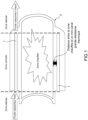
- This block 2 often consists of a hollow axisymmetric structure formed of hollow cylinders having two different outer diameters for three different zones along the axial coordinate: a smaller outer diameter for the side zones and a larger diameter for a central zone which contains the mini-channels 1.
- the mini-channels 1 cannot be placed at a constant distance (along their length) from the heated wall if the element to be cooled has a non-cylindrical internal shape (for example the cavities of the gyrotron are conical) because a straight mini-channel on an inclined element is at a different distance from the cavity at different points of the mini-channel. Also, uneven cooling occurs.
- the distance between the heated wall and the flow of heat transfer fluid is limited by the presence of intermediate material necessary for the production of the elements and cannot be minimized down to the thickness limited by the vacuum seal tv.
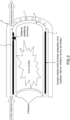
- the imperfect contact between blocks 3, 4, as shown in [ Fig.2 ] behaves like a thermal impedance. If the solder or adhesive 5 is located in a limited region, for example by soldering or bonding by circular wires, the contact remaining between the two (or more) blocks 3, 4 results in a imperfect contact, which consequently translates into an inevitable thermal contact resistance.
- solder 6 interposed between these blocks 3, 4, as illustrated in [ Fig.3 ] has the following two disadvantages. If the alloy is present on the whole plane under a mini-channel 1, edge effects occur at the interface and limit the heat extraction, behaving like a thermal resistance. In addition, the presence of solder 6 between the blocks 3, 4 introduces the manufacturing risk of obstructing certain mini-channels 1 which, to be mitigated, leads to limiting the number of mini-channels 1.
- the structure 4 which surrounds the mini-channels 1 exerts a mechanical stress opposing the thermal expansion of the internal block, causing mechanical stresses.
- the minimum distance between a mini-channel and the directly heated wall can limit the mechanical stability of the element to be cooled: in order to reduce the thermal resistance, the cooling flow must circulate as close as possible to the heated wall. In this case, the low thickness of the material between the mini-channel and the wall to be cooled cannot provide the necessary rigidity and undesirable deformations may occur. As the mini-channel approaches the wall to be cooled, the block of material decreases in size exposing the entire system to a lack of mechanical rigidity and stability. A minimum distance ensuring mechanical stability t M , must be interposed between the heated and cooled walls. As a result, the thickness limited by the vacuum seal t V cannot be achieved and the heat transfer is reduced.
- the mini-channels cross the entire length of the cylindrical object to be cooled, causing an inhomogeneity in the axial temperature profile, under thermal loads, which presents a very high peak in their axial distribution. This causes mechanical stresses in the structure due to the high axial thermal gradient.
- the straight profile of a mini-channel results in a constant distance between the fluid flow and the heated surface. If a non-uniform thermal load along the mini-channels is present, a minimization of the temperature peak on the heated surface is not possible.
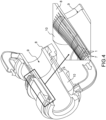
- Fig 4 represents a state of the art of mini-channels 1 formed by grooves 7 on the external surface of the wall 8 of an internal cavity 9 and of a jacket 10.
- the structure 10 which is connected to the ends of the element to be cooled 9 exerts a mechanical stress in the axial direction opposing the thermal expansion of the internal element 9 causing mechanical stresses.
- the single heat transfer fluid inlet located in a certain position, confers a high speed to the heat transfer fluid close to the inlet itself.
- the heat transfer fluid velocity is lower far from the inlet.
- heat extraction is reduced far from the coolant inlet and the temperature of the element to be cooled is azimuthally inhomogeneous.
- An object of the invention is to overcome the problems cited above.
- the proposed invention aims to improve the cooling and the thermomechanical robustness of the element to which it can be applied.
- this solution can be applied to cavities, collectors and any element that needs to be cooled.
- cylindrical, square or conical geometries as well as frustoconical geometries can be the subject of the application of the cooling circuit with routed mini-channels.
- the first thickness is at least twice greater than the second thickness
- the third thickness is at least twice greater than the second thickness
- the system comprises at least three connection points to connect in longitudinal translation the sleeve and the internal cavity wall.
- a connection point comprises a solder and/or solder and/or heat shrink.
- the system includes an expandable gusset in the outer shell.
- the system comprises at least one inlet of the cooling circuit in the outer casing leading to the space between the outer casing and the jacket, so that the path of a heat transfer fluid from said inlet to to the mini-channels is maximized in order to homogenize the axial velocity of the fluid in said space.
- a mini-channel is straight or curved.
- a mini-channel has a circular, semi-circular or rectangular section.
- the system comprises a heat transfer fluid distributor comprising the casing disposed outside the outer casing to form a heat transfer fluid chamber disposed above several inlets in the outer casing leading to the space between the outer envelope and the shirt.
- said inlets of the heat transfer fluid distributor are arranged circularly on the outer casing.
- the inlets are rectangular and/or circular and/or square, and/or semi-circular.
- a mini-channel groove comprises a porous medium.
- the outer casing comprises layers of ceramic or metallic base porous material (for example tungsten or rhenium foam or ultramet ® ).
- the internal cavity wall comprises copper mixed with ceramic particles of alumina, in particular Glidcop ® .
- the system is a resonant cavity, a vacuum electron tube or a gyrotron.
- a shirt is a press-fit cylindrical piece.
- the first thickness is at least twice greater than the second thickness
- the third thickness is at least twice greater than the second thickness
- connection point 20a or a continuous connection can comprise a solder and/or solder and/ or heat shrink.
- the radial extensions can be made with pins, for example 4 pins 20a, or with a continuous radial extension containing openings.
- the electronic system can include an expandable bellows 21 in the outer casing 11.
- the heat transfer fluid can include water, air or oil.
- the mini-channel cooling circuit 19 comprises a network of small-sized mini-channels 19, typically with a diameter between 0.2 mm and 2 mm if they are circular, or with an area between ⁇ /100 mm2 and ⁇ mm2, in which circulates a heat transfer fluid serving to cool the internal cavity 13.
- the distance between the flow of heat transfer fluid and the wall of internal cavity can be minimized down to the minimum distance which ensures vacuum tightness tv.
- the short length of a mini-channel 19 is due to the channel inlet, which must be located in correspondence of the thermal load peak. This makes it possible to operate the inlet of the mini-channels 19 at very high speed, which results in a greater heat transfer coefficient than in the rest of the mini-channels, corresponding to the continuation of the path of the coolant fluid, exactly in the peak zone (the zone where the maximum thermal load is present).
- the consequence of this design is a flatter or constant temperature profile along the axial coordinate because the cold fluid jet is directed near the maximum of the heat load. Consequently, the better cooling allows a minor thermal expansion of the materials which low expansion forces impart to the sleeve 17 which is therefore subject to lower mechanical stresses.
- Another advantage of a short mini-channel is the significant reduction in the load losses distributed along the mini-channels, therefore a reduction in the total load losses of the circuit, in particular half of the load losses with respect to the state of the art (2 - 3 bar instead of 5 - 6 bar for fluid flow rates around 45 - 55 l/min).
- mini-channels are made between two different elements: possibly made with two different materials: the internal cavity 13, with a low coefficient of thermal expansion, typically between 16 ⁇ m/m K and 17 ⁇ m/m K (generally copper mixed with alumina ceramic particles) and the jacket 17, with high thermal conductivity, typically between 17.5 ⁇ m/m K and 18 ⁇ m/m K (generally copper).
- the internal cavity 13 with a low coefficient of thermal expansion, typically between 16 ⁇ m/m K and 17 ⁇ m/m K (generally copper mixed with alumina ceramic particles) and the jacket 17, with high thermal conductivity, typically between 17.5 ⁇ m/m K and 18 ⁇ m/m K (generally copper).
- the outer coaxial element or sleeve 17 is implemented by a hollow and flexible outer structure, which follows the thermal expansion of the inner coaxial element or internal cavity 13, reducing the mechanical stresses which could be induced in the structure.
- the thickness of the second part 18b of the flexible portion 18 would typically be between 0.3 and 3 mm, as illustrated in the figure 8 .
- the thickness ratios between the first end part 18a, second part 18b, and part 17c allow the wall 12 of the internal cavity 13 to expand without significant mechanical stress but rather comparable to thermal stress, thanks to the particularly flexible 18, which allows the sleeve 17 to expand by increasing its diameter under the effect of the thermal expansion of the wall 12 of the internal cavity 13.
- the level of mechanical stress at the interface between the wall 12 and the flexible portion 18 is less than or equal to the thermal stress which would be exerted on the outer surface of the wall 12 if the flexible portion 18 were not present, or if there were Rashing rings in its place.
- the particularly flexible portion 18 of the jacket 17 can widen by increasing its diameter under the effect of the water flow which passes through the mini-channels 19.
- the particularly flexible portion 18 of the jacket 17 can also shrink by reducing its diameter under the effect of the water flow.
- a distributor 22 of heat transfer fluid comprising an injection 26 of heat transfer fluid, a casing 23 disposed outside the outer casing 11 to form a chamber 24 of heat transfer fluid disposed above several inlets 25 in the outer casing 11 leading to the space between the outer casing 11 and the jacket 17.
- the jacket 17 also serves as a fluid distributor to homogenize the speed of the heat transfer fluid.
- the mini-channels 19 can comprise at least one curvature. Such a curvature allows a mini-channel 19 to come as close as possible to the heated wall 12 and, if necessary, to overcome the solder if solder points are present at the ends of the cavity.
- a curved mini-channel 19 reaches (more in depth) the material of the wall 12 of the internal cavity 13 allowing the flow of heat transfer fluid to be in direct contact with the part of the wall 12 closest to the internal cavity 13 , the most heated. That allows to improve the heat transfer only in the zones characterized by the thermal load peak, resulting in a more homogeneous axial temperature profile, avoiding mechanical stresses.
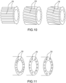
- the path of a mini-channel 19, in a plane transverse to the direction of the heat transfer fluid can be straight, inclined or bent, as shown in [ Fig.10 ].
- the section of a mini-channel 19 can have any geometric shape, such as a circular, semi-circular, square, or rectangular shape, the [ Fig.11 ] illustrates some examples.
- a shape including an arc is preferred to exploit the force discharge.
- the cooling circuit 14 with mini-channels 19 can be made in any geometric arrangement (cylindrical, square, conical, conical, etc.) of the wall 12 of the internal cavity 13 to be cooled.
- the expandable flexible bellows 21 allows the expansion of the wall 12 to be cooled by eliminating the stresses that would have been applied by other connected elements.
- the cooling circuit 14 is a dynamic system that evolves over time: the section and position of a mini-channel 19 vary during the heating process until it reaches a stable state, thanks to the axial and radial elongation of the system heated.
- the dynamic movement of the system is temperature controlled.
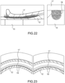
- FIG.12 represents in particular an embodiment of the distributor 22 of heat transfer fluid, in an embodiment devoid of extensible bellows 21.
- the present invention allows the production (by brazing, welding or gluing by heat-shrinkage of various elements) of a cooling circuit 14 for which a low thermal resistance is present between the surface to be cooled of the wall 12 and the heat transfer fluid, while ensuring the integrity and mechanical stability of the materials to limit the deformations induced by thermal expansion while controlling the mechanical and thermal stresses.
- the present invention improves thermal management by means of an optimized section and position of the mini-channels 19.
- Heat transfer is maximized by minimizing the distance between the heat transfer fluid and the heated inner wall 12 while providing a safety margin for vacuum sealing. This distance can be minimized down to the thickness limited by the vacuum seal tv.
- Heat transfer is improved and allows a significant reduction in temperature with a consequent limitation of thermal stress.
- the flow of heat transfer fluid is in direct contact with the element to be cooled (wall 12) without intermediate elements or solder/solder alloys.
- the section of the channel along the direction of the flow of the heat transfer fluid can be curved in order to approach in depth as close as possible to the heated wall 12 to be cooled.
- cooling can be implemented with a minimum thickness under a mini-channel ranging from 0.1 to 1 mm, a number of channels varying from 50 to 200 units, the section of a mini-channel is composed of two zones: a zone of semi-circular cross-section with a diameter of approximately ranging from 0.1 to 1 mm and a zone of rectangular cross-section with sides of approximately ranging from 0.1 to 1 mm.
- cooling can be implemented with a minimum thickness under a mini-channel ranging from 0.8 to 1 mm, a number of channels varying from 50 to 90 units , the cross-section of a mini-channel is composed of two zones: a zone of semi-circular cross-section with a diameter of approximately 1mm and a zone of rectangular cross-section with sides of approximately 0.5 and 0.7 mm, the radial spacing between the channels being similar to the radial width of the channels.
- the present invention improves stress management and thermal expansion.
- Such a system limits the thermal expansion by applying moderate mechanical stresses (compared to the mini-channel circuits of the state of the art) by the outer casing 11 on the wall 12 of the inner cavity 13 coaxial.
- the entrance to a mini-channel 19, where the maximum convective heat transfer is observed, is located near the peak of the heat load. This minimizes the temperature peak on the heated surface and results in a "flatter" temperature profile, resulting in lower thermal stresses.
- the possibility of the materials not to expand makes it possible not to create significant mechanical stresses.
- the level of stress is maintained at the same level as the actual Raschig ring cavities while greatly improving heat transfer.
- the outer coaxial element is made in the form of an empty and flexible structure, called jacket 17 which exerts moderate mechanical stresses on the inner coaxial element, the wall 12 of internal cavity 13 while it expands on heating, as shown in the [ Fig.13 ].
- the section of a mini-channel 19 may contain an arcuate element to exploit the principle of force relief typical of the arc.
- a thicker wall alternating with the mini-channels 19 provides mechanical stability, as shown in [ Fig. 14 ].
- the present invention improves the thermal homogeneity and limits the consequent anisotropic deformations by means of a homogenizer implemented by means of a distributor 22 of heat transfer fluid with two stages.
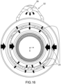
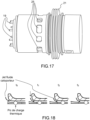
- An exemplary embodiment of the distributor 22 is shown in detail on the [ Fig.15 ], [ Fig.16 ] And [ Fig.17 ].
- a heat transfer fluid inlet is arranged around the outer casing 11: inlets 25 or narrow holes are placed close to the injection 26 of the heat transfer fluid and larger holes are placed further from the injection of the heat transfer fluid whereas other medium-sized holes are placed in the side opposite the injection (where the two components of the radial velocity which separate near the injection meet).
- the distributor 22 is presented as a set of multiple inlets 25 in which the speed of the heat transfer fluid is constant for different positions as well as at different distances from the point of injection 26 of fluid. As a result, the axial velocity of the coolant is constant along the azimuthal direction.
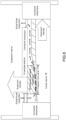
- the secondary distribution chamber 24 is put in place by the jacket 17 to finally homogenize the speed of the heat transfer fluid in the direction of entry into the mini-channels 19, as illustrated in [ Fig.9 ].
- a mini-channel inlet 19 is located near the heat load peak, to exploit the high heat transfer coefficient due to the high heat transfer fluid velocity.
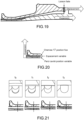
- the position of the peak heat load shifts to the right, as shown in [ Fig.18 ] And [ Fig.19 ] along the axial coordinate due to thermal deformations of the inner surface.
- the proposed invention solves this problem by realizing the cooling circuit as a dynamic system that evolves over time, the geometry of which changes during heating and cooling: the heat transfer (as well as the speed of the heat transfer fluid and the pressure drop ) is temperature controlled.
- the axial position of the coaxial casing of the heat transfer fluid distributor 22 is controlled by the temperature of the cavity 13 (thanks to its axial thermal expansion): it follows the position of the load peak during the evolution of the heating transient to a stable position.
- the coaxial outer element (housing of the heat transfer fluid distributor 22) is connected to the free section of the cavity 13.
- the thermal load peak is moved to a certain position (in the gyrotrons, towards the ascending cone) .
- the invention makes it possible to direct the jets of heat transfer fluid as close as possible to the thermal load peak while the cavity 13 is heating.
- the thermal expansion of the cavity 13 is used to move the jacket 17: the position of the heat transfer fluid inlet at the inlet of a mini-channel 19 is controlled by the thermal expansion of the cavity 13: while the cavity 13 expands, the sleeve 17 moves, providing the input of the mini-channel 19 to follow the evolution of the position of the thermal load peak.
- the cross section of the mini-channels 19 is temperature controlled: a space is left between the outer wall 12 of the cavity 13 (groove) and the inner wall of the sleeve 17, which is kept cold, consequently a by -pass is present at the start of the heating and the bypass gradually decreases until it reaches the steady state when the section of the mini-channels 19 reaches the nominal shape.
- a bypass exists between the cavity and the jacket 17, hence the opening of the mini-channels.
- mini-channels 19 are activated.
- the mini-channels 19 reach their final cross section.
- a third level of fluid distribution can be located at the outlet around the shaft: narrow holes are placed close to the fluid extraction and larger holes are placed further away.
- the structure results in a set of multiple outputs. The effect is to increase the azimuthal homogeneity of the outlet pressure distribution. This causes a better azimuthal distribution of the fluid velocity in the channels and consequently a more homogeneous azimuthal distribution of the temperature, as demonstrated by numerical calculations based on the geometry of the Thales TH1507U Gyrotron.
- the mini-channels 19 can include the presence of porous media deposited inside the mini-channels 19.
- the effects of this configuration are mainly the increase in the heat exchange surface, the reduction of the laminar sub-layer close to the wall and the promotion of fluid mixing.
- the number of mini-channels 19 can be increased compared to the solution of empty mini-channels 19 and the spacing between the mini-channels can be reduced up to at 1/10 of the radial spacing of the mini-channels. This is possible because the presence of the porous medium introduces a certain mechanical robustness.
- this solution Compared to a traditional porous media heat exchanger, this solution has improved mechanical stability, it incorporates the double-stage fluid distributor and it exploits the temperature-controlled time-evolving dynamic geometry.
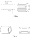
- the present invention can be made by milling and brazing, welding or bonding by heat-shrinkage of two elements or by Galvano copper forming or 3D additive manufacturing of a second element on a first element.
- the machining process is relatively simple and conforms to state-of-the-art manufacturing procedures.
- the same process can be obtained by additive manufacturing of the external element, provided that the materials generated by additive manufacturing comply with the requirements of thermal conductivity, surface roughness, elastic limit and breaking stress required by the application considered (the most concerned is the gyrotron).
- This solution can be applied to all electronic tubes and electronic devices as well as semiconductor devices or passive elements that need to be cooled.
- any geometric arrangement of the element to be cooled can benefit from the proposed invention: geometries such as cylindrical, square or conical as well as frustoconical can be the subject of the application of the mini-channel cooling circuit.
- the cooling of the cavities of the gyrotron is a particularly advantageous application of the proposed invention.
Landscapes
- Engineering & Computer Science (AREA)
- Physics & Mathematics (AREA)
- Plasma & Fusion (AREA)
- Spectroscopy & Molecular Physics (AREA)
- Computer Networks & Wireless Communication (AREA)
- Power Engineering (AREA)
- Cooling Or The Like Of Semiconductors Or Solid State Devices (AREA)
- Cooling Or The Like Of Electrical Apparatus (AREA)
Applications Claiming Priority (1)
| Application Number | Priority Date | Filing Date | Title |
|---|---|---|---|
| FR2110917A FR3128353A1 (fr) | 2021-10-14 | 2021-10-14 | Système électronique muni d'un circuit de refroidissement à fluide caloporteur |
Publications (2)
| Publication Number | Publication Date |
|---|---|
| EP4167264A2 true EP4167264A2 (de) | 2023-04-19 |
| EP4167264A3 EP4167264A3 (de) | 2023-06-28 |
Family
ID=80122424
Family Applications (1)
| Application Number | Title | Priority Date | Filing Date |
|---|---|---|---|
| EP22200570.4A Pending EP4167264A3 (de) | 2021-10-14 | 2022-10-10 | Elektronisches system mit kühlmittelkreislauf |
Country Status (5)
| Country | Link |
|---|---|
| US (1) | US11871504B2 (de) |
| EP (1) | EP4167264A3 (de) |
| JP (1) | JP2023059242A (de) |
| CN (1) | CN115988827A (de) |
| FR (1) | FR3128353A1 (de) |
Cited By (1)
| Publication number | Priority date | Publication date | Assignee | Title |
|---|---|---|---|---|
| CN119212196A (zh) * | 2024-08-13 | 2024-12-27 | 中国科学院近代物理研究所 | 一种用于超导加速模组的复式绝热波纹管及超导加速模组 |
Family Cites Families (6)
| Publication number | Priority date | Publication date | Assignee | Title |
|---|---|---|---|---|
| NL282676A (de) * | 1961-08-31 | |||
| JPH04155728A (ja) * | 1990-10-19 | 1992-05-28 | Mitsubishi Electric Corp | 電子ビーム管装置 |
| JPH06267441A (ja) | 1993-03-11 | 1994-09-22 | Toshiba Corp | マイクロ波管装置 |
| DE102011007553A1 (de) * | 2011-04-15 | 2012-10-18 | Mht Mold & Hotrunner Technology Ag | Kühlhülse mit Stützelement |
| DE102012213059A1 (de) * | 2012-07-25 | 2014-01-30 | Siemens Aktiengesellschaft | Kühlmantel |
| CN114142660B (zh) * | 2020-09-04 | 2023-06-23 | 约克(无锡)空调冷冻设备有限公司 | 电机 |
-
2021
- 2021-10-14 FR FR2110917A patent/FR3128353A1/fr active Pending
-
2022
- 2022-09-27 US US17/954,136 patent/US11871504B2/en active Active
- 2022-09-29 JP JP2022155998A patent/JP2023059242A/ja active Pending
- 2022-10-10 EP EP22200570.4A patent/EP4167264A3/de active Pending
- 2022-10-11 CN CN202211240283.8A patent/CN115988827A/zh active Pending
Cited By (1)
| Publication number | Priority date | Publication date | Assignee | Title |
|---|---|---|---|---|
| CN119212196A (zh) * | 2024-08-13 | 2024-12-27 | 中国科学院近代物理研究所 | 一种用于超导加速模组的复式绝热波纹管及超导加速模组 |
Also Published As
| Publication number | Publication date |
|---|---|
| US20230120648A1 (en) | 2023-04-20 |
| FR3128353A1 (fr) | 2023-04-21 |
| EP4167264A3 (de) | 2023-06-28 |
| US11871504B2 (en) | 2024-01-09 |
| CN115988827A (zh) | 2023-04-18 |
| JP2023059242A (ja) | 2023-04-26 |
Similar Documents
| Publication | Publication Date | Title |
|---|---|---|
| EP0982976B1 (de) | Auf hohen thermischen Belastungen abgestimmter Plasmamotor mit geschlossenem Elektronendrift | |
| EP2256876B1 (de) | Extremer Hochleistungssteckverbinder | |
| EP3857030B1 (de) | Anordung für eine turbine einer strömungsmaschine und zugehörige strömungsmaschine | |
| EP4167264A2 (de) | Elektronisches system mit kühlmittelkreislauf | |
| WO2019077265A1 (fr) | Element de repartition d'un fluide de refroidissement et ensemble d'anneau de turbine associe | |
| FR3086047A1 (fr) | Dispositif de thermorégulation et procédé de thermorégulation d’un module électrique | |
| EP3469206B1 (de) | Raketentriebwerkbrennkammer mit rippen mit variabler zusammensetzung | |
| FR3095668A1 (fr) | Ensemble d’anneau de turbine monté sur entretoise | |
| EP4166881B1 (de) | Modul zur herstellung eines wärmerohrs mit kapillarpumpe mit wiedereintrittsnuten | |
| EP0231311A1 (de) | Verfahren zur herstellung metallischer gussstücke mit eingegossenem rohr | |
| EP3737901A1 (de) | Kalttiegel und zugehöriger kühlverteiler für eine induktionsheizvorrichtung | |
| FR3132412A1 (fr) | Torche de coupage plasma munie d'un système de verrouillage amelioré | |
| WO2022223905A1 (fr) | Ensemble d'anneau de turbine monté sur entretoise | |
| FR3107801A1 (fr) | Applicateur d’onde haute fréquence, coupleur et dispositif associés pour la production d’un plasma | |
| WO2024038238A1 (fr) | Élément statorique d'une machine électrique d'un aéronef | |
| EP1123567B1 (de) | Überdimensionierter höchstfrequenzabsorber für hohe dauerleistung und seine verwendung als kalorimeter | |
| FR3154753A1 (fr) | Ensemble d’anneau de turbine avec flasque annulaire amont de support d’anneau avec rattrapage de dilatation différentielle | |
| WO2024170714A1 (fr) | Procédé de fabrication d'échangeur de chaleur par projection dynamique à froid et échangeur de chaleur associé | |
| FR2867608A1 (fr) | Refroidisseur pour composant electronique de puissance | |
| EP3568574A1 (de) | Turbinenringanordnung | |
| FR3132411A1 (fr) | Torche de coupage plasma munie d'un empilement de consommables | |
| FR3100571A1 (fr) | Canalisation pour une turbomachine d’aéronef | |
| EP4627606A1 (de) | Verfahren zur herstellung eines magnetkerns mit einem in einem arm eingeschlossenen element | |
| FR3154751A1 (fr) | Ensemble d’anneau de turbine avec bride radiale améliorée | |
| FR3132408A1 (fr) | Torche de coupage plasma avec refroidissement indirect des consommables |
Legal Events
| Date | Code | Title | Description |
|---|---|---|---|
| PUAI | Public reference made under article 153(3) epc to a published international application that has entered the european phase |
Free format text: ORIGINAL CODE: 0009012 |
|
| STAA | Information on the status of an ep patent application or granted ep patent |
Free format text: STATUS: THE APPLICATION HAS BEEN PUBLISHED |
|
| AK | Designated contracting states |
Kind code of ref document: A2 Designated state(s): AL AT BE BG CH CY CZ DE DK EE ES FI FR GB GR HR HU IE IS IT LI LT LU LV MC ME MK MT NL NO PL PT RO RS SE SI SK SM TR |
|
| PUAL | Search report despatched |
Free format text: ORIGINAL CODE: 0009013 |
|
| P01 | Opt-out of the competence of the unified patent court (upc) registered |
Effective date: 20230517 |
|
| AK | Designated contracting states |
Kind code of ref document: A3 Designated state(s): AL AT BE BG CH CY CZ DE DK EE ES FI FR GB GR HR HU IE IS IT LI LT LU LV MC ME MK MT NL NO PL PT RO RS SE SI SK SM TR |
|
| RIC1 | Information provided on ipc code assigned before grant |
Ipc: H01J 25/02 20060101ALI20230525BHEP Ipc: H01J 23/12 20060101ALI20230525BHEP Ipc: H01J 23/033 20060101AFI20230525BHEP |
|
| STAA | Information on the status of an ep patent application or granted ep patent |
Free format text: STATUS: REQUEST FOR EXAMINATION WAS MADE |
|
| 17P | Request for examination filed |
Effective date: 20231003 |
|
| RBV | Designated contracting states (corrected) |
Designated state(s): AL AT BE BG CH CY CZ DE DK EE ES FI FR GB GR HR HU IE IS IT LI LT LU LV MC ME MK MT NL NO PL PT RO RS SE SI SK SM TR |
|
| RIN1 | Information on inventor provided before grant (corrected) |
Inventor name: SAVOLDI, LAURA Inventor name: DIFONZO, ROZA Inventor name: ALLIO, ANDREA Inventor name: MARCHESIN, RODOLPHE Inventor name: LEGRAND, FRANCOIS Inventor name: LEGGIERI, ALBERTO |