EP4166994B1 - Sensor zum überwachen eines bereichs - Google Patents
Sensor zum überwachen eines bereichs Download PDFInfo
- Publication number
- EP4166994B1 EP4166994B1 EP22197414.0A EP22197414A EP4166994B1 EP 4166994 B1 EP4166994 B1 EP 4166994B1 EP 22197414 A EP22197414 A EP 22197414A EP 4166994 B1 EP4166994 B1 EP 4166994B1
- Authority
- EP
- European Patent Office
- Prior art keywords
- code
- mismatched
- mismatched filter
- detection signal
- sensor
- Prior art date
- Legal status (The legal status is an assumption and is not a legal conclusion. Google has not performed a legal analysis and makes no representation as to the accuracy of the status listed.)
- Active
Links
Images


Classifications
-
- G—PHYSICS
- G01—MEASURING; TESTING
- G01V—GEOPHYSICS; GRAVITATIONAL MEASUREMENTS; DETECTING MASSES OR OBJECTS; TAGS
- G01V8/00—Prospecting or detecting by optical means
- G01V8/10—Detecting, e.g. by using light barriers
- G01V8/20—Detecting, e.g. by using light barriers using multiple transmitters or receivers
Definitions
- a sensor comprising a plurality of radiation emitters for generating a light curtain is described for instance in Chinese Patent Application CN 203877712 U .
- a sensor comprising the features according to the preamble of claim 1 is disclosed in " Mismatched Filters for Incoherent Pulse Compression in Laser Radar” (Michael J Lindenfeld; IEEE TRANSACTIONS ON AEROSPACE AND ELECTRONIC SYSTEMS, 20201116 IEEE SERVICE CENTER, PISCATAWAY, NJ, US - ISSN 0018-9251 ).
- the accuracy of surveillance channels of sensors such as light curtain devices may be impaired by interference of ambient light or radiation from other sources. For instance, if an object interrupts one of the surveillance channels and should therefore be detected, but the corresponding detector of the surveillance channel is illuminated by ambient light or light of another source, the object may remain undetected.
- An objective of the present invention is to propose a sensor and a light curtain device which are optimized with regard to above described interference problems.
- a further objective of the present invention is to provide an improved method of fabricating such a sensor.
- An embodiment of the present invention relates to a sensor according to claim 1.
- the first code can also be referred to as "transmission" code because it is used for coding before transmitting the data. For instance, if the signal path between the first radiation emitter and the first detector is interrupted, the sensor should detect this situation. However, in case of severe interference, radiation from other sources such as ambient light might lead to a detection signal of the first detector nonetheless. In this latter scenario, an object that interrupts the signal path and should therefore be detected, might remain undetected.
- the evaluation unit is preferably configured to generate a warning signal if the cross-correlation between the first detection signal and the first mismatched filter code is below a given (first) threshold.
- the evaluation unit may be configured to generate a confirmation signal if the cross-correlation between the first detection signal and the first mismatched filter code exceeds a given (second) threshold.
- the first and second threshold may be identical.
- the first code (first transmission code) is preferably a binary or bi-polar code.
- the first mismatched code is preferably a non-binary code, for instance a decimal code.
- the surveillance channels preferably differ in the codes that they use. For instance, one surveillance channel may use one code (e.g. one Gold code), whereas another surveillance channel (preferably the adjacent surveillance channels) may use another code (e.g. another Gold code).
- one surveillance channel may use one code (e.g. one Gold code)
- another surveillance channel preferably the adjacent surveillance channels
- another code e.g. another Gold code
- the evaluation unit is preferably configured to generate a warning signal if the cross-correlation between the second detection signal and the second mismatched filter code is below a given (first) threshold.
- the evaluation unit may be configured to generate a confirmation signal if the cross-correlation between the second detection signal and the second mismatched filter code exceeds a given (second) threshold.
- the first and second threshold may be identical.
- the first mismatched filter code and the second mismatched filter code are preferably orthogonal.
- the first code and the second code are preferably orthogonal.
- the first code and the second mismatched filter code are preferably orthogonal.
- the second code and the first mismatched filter code are preferably orthogonal.
- Matrices H1 and H2 each comprise M columns. M corresponds to the length of the first and second mismatched filter code. M is larger than the number N of vector elements of the first and second code.
- the sensor may comprise a first group of surveillance channels and a second group of surveillance channels.
- the first group of surveillance channels is operated based on said first code having the first code length and said first mismatched code that has a code length larger than the first code length.
- the second group of surveillance channels is operated based on said second code having the second code length and said second mismatched code that has a code length larger than the second code length.
- the surveillance channels are preferably arranged such that neighboring surveillance channels of the same group are separated by a single surveillance channel of the other group.
- the first group of surveillance channels is preferably formed by radiation emitters identical or similar to said first radiation emitter (as described above) and by detectors identical or similar to said first detector (as described above).
- the second group of surveillance channels is preferably formed by radiation emitters identical or similar to said second radiation emitter (as described above) and by detectors identical or similar to said second detector (as described above).
- the sensor may comprise one or more additional surveillance channels that are operated based on an additional code that differs from the first and second code, and a corresponding additional mismatched code that differs from the first and second mismatched code.
- Each additional code and each additional mismatched code preferably fulfil the same requirements as the first and second code and the first and second mismatched code, as discussed above, with respect to one another and with respect to the first and second code and the first and second mismatched code.
- the sensor is preferably a light curtain sensor.
- the surveillance channel or channels are preferably free-beam surveillance channels.
- the streams of data are preferably transmitted via free-space beam propagation.
- a further embodiment of the invention relates to a method according to claim 6.
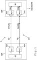
- Figure 1 depicts a first exemplary embodiment of a sensor 3 according to the present invention.
- the sensor 3 of Figure 1 is an object detection sensor that provides two adjacent single free-beam surveillance channels SVC.
- the sensor 3 is configured to generate a clearance signal CS if the free-beam surveillance channels SVC are uninterrupted and undisturbed. If one of the free-beam surveillance channels SVC is interrupted, an object detection signal OS is generated. If one of the free-beam surveillance channels SVC is uninterrupted, but disturbed a warning signal WS is generated.
- the sensor 3 comprises a transmitter device 305 and a receiver device 306.
- the transmitter device 305 comprises a first radiation emitter Tx1 and a second radiation emitter Tx2 which both may be controlled by an emitter control unit 35 of the transmitter device 305.
- the radiation generated by the radiation emitters may be visible light or invisible light (e. g. infrared or ultraviolet light) or any other electromagnetic radiation.
- the emitter control unit 35 controls the first radiation emitter Tx1 such that the first radiation emitter Tx1 generates a first radiation beam B1 that conveys a first stream of data.
- the data are coded based on a first binary/bipolar (transmission) code having a first code length.
- the first code length can be six, for instance, as discussed further below in an exemplary fashion.
- the emitter control unit 35 controls the second radiation emitter Tx2 such that the second radiation emitter Tx2 generates a second radiation beam B2 that conveys a second stream of data.
- the latter data are coded based on a second binary/bipolar (transmission) code having a second code length.
- the second code length can be six, for instance, as discussed further below in an exemplary fashion.
- the first beam B1 and its allocated first stream of data as well as the second beam B2 and its allocated second stream of data are transmitted towards the receiver unit 306 via free-space beam propagation.
- the receiver device 306 comprises a first detector Rx1 and a second detector Rx2.
- the first radiation emitter Tx1 is individually assigned to the first detector Rx1 such that the first radiation emitter Tx1 and the first detector Rx1 form a first one of said two surveillance channels SVC.
- the second radiation emitter Tx2 is individually assigned to the second detector Rx2 such that the second radiation emitter Tx2 and the second detector Rx2 form a second one of said two surveillance channels SVC.
- An evaluation unit 36 of the receiver device 306 is configured to evaluate detection signals DS1 and DS2 of the detectors Rx1 and Rx2.
- the evaluation unit 36 carries out a correlation analysis with respect to the first detection signal DS1 and the received first stream of data.
- the correlation analysis includes calculating the correlation between the first detection signal DS1 and a first mismatched code that has a code length larger than the first code length of the first code.
- the first mismatched code is preferably a decimal code.
- the evaluation unit 36 generates a warning signal WS if the cross-correlation between the first detection signal DS1 and the first mismatched filter code is below a given threshold.
- the length of the first mismatched filter code can be twelve, for instance, as discussed further below in an exemplary fashion.
- the evaluation unit 36 also carries out a correlation analysis with respect to the second detection signal DS2 and the received second stream of data.
- the correlation analysis includes calculating the correlation between the second detection signal DS2 and a second mismatched code that has a code length larger than the second code length of the second code.
- the evaluation unit 36 generates a warning signal WS if the cross-correlation between the second detection signal DS2 and the second mismatched filter code is below a given threshold.
- the length of the second mismatched filter code can be twelve, for instance, as discussed further below in an exemplary fashion.
- the first mismatched code is preferably a decimal code.
- the evaluation unit 36 generates a clearance signal CS if the free-beam surveillance channels SVC are both uninterrupted and undisturbed.
- the surveillance channels SVC may be deemed uninterrupted if both detectors Rx1 and Rx2 receive radiation and generate detection signals that have a sufficient signal strength (e.g. minimal amplitude).
- the surveillance channels SVC may be deemed undisturbed if the detections signals DS1 and DS2 pass the cross-correlation tests mentioned above, i.e. if the cross-correlation between the detection signals and the assigned mismatched filter codes exceed said given threshold.
- the evaluation unit 36 generates the object detection signal OS if one or both of the surveillance channels are interrupted.
- the surveillance channels may be deemed interrupted if the detectors Rx1 and Rx2 do not generate a sufficient detection signal, e. g. do not provide a detection signal having a required minimum amplitude.
- the adjacent surveillance channels When using multiple surveillance channels SVC in close proximity to one another, the adjacent surveillance channels preferably differ with respect to their codes and assigned mismatched codes.
- the sensor 3 provides two different types of surveillance channels labeled A and B. Both types may have identical hardware but differ with respect to the codes assigned to them, with type A using one code x and type B using another code y.
- the B-type detector 310 receives a signal from the assigned B-type radiation emitter 304. But due to close proximity, it is possible that it can also receive signals from the A-type radiation emitter 303.
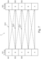
- the sensor 3 comprises an emitter array 501 having a plurality of radiation emitters 503, 507 and 508, and a receiver array 502 having a plurality of radiation detectors 504, 505 and 506, as shown in Figure 7 .
- the B-type second detector 505 will receive a signal from the assigned B-type radiation emitter 503. But due to close proximity, it is possible that it can also receive signals from the adjacent A-type radiation emitters 507 and 508. The interference from other B-type transmitter units can usually be ignored due to the distance.
- PN Pseudo-Noise
- ML sequences ML sequences
- Kassami codes Pseudo-Noise
- One drawback to using these codes are that the code length, N, should be increased to achieve a reasonable autocorrelation and cross-correlation response. For a small N the sidelobes of the autocorrelation function are too high and as a result it will not be able to suppress interference adequately. For a larger N, the problem is more of processing power and bandwidth as we have to send/receive N chips/bits in a specific time, which based on the application, can be as low as 10s of microseconds. This can increase the cost of the sensor substantially. Therefore, we propose using mismatched (filter) codes. The length of the mismatched (filter) codes is larger than the length of the assigned codes which in turn allow using relatively short codes for transmission. Such mismatched (filter) codes will be explained hereinafter in an exemplary fashion.
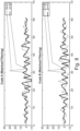
- Figure 8 shows the correlation of two such orthogonal codes A and B.
- the symbol A ⁇ B represent cross-correlation (e. g. as described in the publication " Code inverse filtering for complete side-lobe removal in binary phase coded pulse compression systems" (R. C. Daniels and V. Gregers-Hansen, IEEE International Radar Conference, 2005., Arlington, VA, 2005, pp. 256-261, doi: 10.1109/RADAR.2005.1435830 ) given by the following equation:
- the resultant vectors x ⁇ and ⁇ will be orthogonal to y and x respectively and also orthogonal to each other.
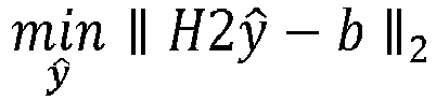
- min x ⁇ ⁇ H 1 x ⁇ ⁇ b ⁇ 2 and min y ⁇ ⁇ H 2 y ⁇ ⁇ b ⁇ 2 b : e , e , ... , 1 , e , ... e , ⁇ is a small threshold value ( ⁇ ⁇ 0,1), and the length of b is given by 2*N+1.
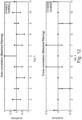
- both auto-correlation functions (x ⁇ x and y ⁇ y) have a central peak and some-what low side-lobes. Since the receivers and transmitters do not need to be physically connected and may therefore be un-synchronized, the detection of the presence of the signal is done by comparing the correlation output to a threshold. So if the side-lobes are high, due to additive noise, it can be mistaken for signal presence, when none is present, or at least not at that sample. This is true for cross-correlation, since the sensor type A can detect signals from neighbouring sensor type B, we have to ensure that the cross-correlation is minimal.
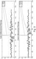
- Figure 11 shows an auto- and cross-correlation of binary codes x and y. It can be seen that the auto-correlation function has a peak in the middle and the side-lobes are relatively low.
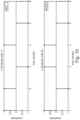
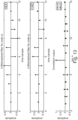
- Figure 12 depicts another example code.
- Equation (9) tries to address this issue by simultaneously decreasing the side-lobes of the correlation function as well as reducing the cross-correlation. This will work well once N has a large value.
- N 6 for our example, although in practice a larger value of N should be used.
- the filter values of the mismatched filter are decimal and may have values of e.g. [0.01, 0.3, 0.4, ...].
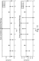
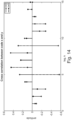
- Figure 14 shows that the cross-correlation has also reduced as compared to the original code.
- the first stream of data (type A coded data) and the second stream of data (type B coded data) may be inverse.
- inverse means that the channels convey logically opposite information. For instance, when the first channel conveys the information "ACTIVE”, the second channel conveys the information "INACTIVE”.
- An information can be transmitted via a single bit.
- the information and the opposite (inverse) information can be transmitted via pre-defined sequences of bits that differ from one another.
- the evaluation unit 36 of Figure 1 may furthermore generate the warning signal WS if the detection signal DS1 of the first detector Rx1 is not inverse or not sufficiently inverse - according to a predefined deviation limit - with respect to the detection signal DS2 of the second detector Rx2.
- the pre-defined deviation limit may for instance require that the percentage of received pairs of information (e.g. bits) that are not inverse (relatively with respect to one another) must be lower than a given maximum limit (e.g. 1%).
- the predefined deviation limit may require that the percentage of received pairs of information (e.g. bits) that are inverse must exceed a given minimum limit (e.g. 99%).
- Each of the surveillance channels SVC preferably defines a surveillance segment or light curtain segment of a light curtain generated by the sensor 3 during operation.
- the surveillance channels may use radiation of the same wavelength.
- the surveillance channels may use different wavelengths.
- adjacent surveillance channels use different wavelengths.
- the radiation beams B1 and B2 emitted by the transmitter device 305 travel through a medium 311, where undesired interference may be added in terms of ambient light as well as interference of other devices operating nearby.
- the transmitter device 305 may comprise polarization filters 303 and 304 that are placed at the output ports of the radiation emitters Tx1 and Tx2.
- the polarization filters 303 and 304 are preferably oriented in such a way that the first beam B1 only comprises light that is polarized in horizontal direction (H-polarization) and the second beam B2 only comprises light that is polarized in vertical direction (V-polarization).
- the receiver device 306 comprises polarization filters 309 and 310 that are placed at the input ports of the detectors Rx1 and Rx2.
- the polarization filters 309 and 310 are preferably oriented in such a way that the first detector Rx1 only receives light that is polarized in horizontal direction (H-polarization) and the second detector Rx2 only receives light that is polarized in vertical direction (V-polarization).
- Such orientations of the polarization filters 303, 304, 309 and 310 allow conveying polar signals (+1/-1) through an optical system which per se is not capable of conveying negative polarities (we can only send 0,+1 through optical systems).
- the streams of data may be sent through frequency shift keying, whereby the radiation beams B1 and B2 emitted by the radiation emitters Tx1 and Tx2 have vastly different frequencies, e.g. emit red and infrared light.
- Appropriate optical filters may be applied to the detectors Rx1 and Rx2 to suppress cross talk between adjacent channels.
- Time domain multiplexing may also (or alternatively) be used to reduce the influence of ambient light and/or interference.
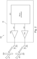
- FIG 2 shows an exemplary embodiment of a transmitter device 305 that can be incorporated in the sensor 3 of Figure 1 .
- the transmitter device 305 comprises a microprocessor 201 that may be used to generate two data streams D1 and D2, in such a way that only one data stream has a "1" or “ON” at a time (and the other has a "0" or “OFF” at the same time).
- the two digital data streams are passed through amplifiers 202 and 203 so that we have enough power for light emitting diodes (LEDs), as shown by 204 and 205, to illuminate an area of interest.
- 206 represents a horizontal polarizing filter
- 207 represents a vertical polarization filter.
- the main idea is that the data stream D1, converted to light signal will have horizontal polarization while the other data stream D2 will have vertical polarization.
- the microprocessor 201 and the amplifiers 202 and 203 form the emitter control unit 35 of Figure 1
- the diodes 204 and 205 form the radiation emitters Tx1 and Tx2 of Figure 1 .
- Figure 3 shows a potential data stream that can be sent over to the receiver device 306, versus time t.
- a bipolar signal BPS is converted to two unipolar signals, labeled H and V. These two unipolar signals H and V form the data signals (streams) D1 and D2, shown in Figure 2 .
- the unipolar signal H may be optically transmitted via the horizontally polarized beam B1 in Figure 1
- the unipolar signal V may be optically transmitted via the vertically polarized beam B2 in Figure 1 .
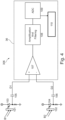
- FIG 4 shows an exemplary embodiment of a receiver device 306 that can be incorporated in the sensor 3 of Figure 1 .
- the received radiation beams B1 and B2 are split into horizontal and vertical polarized components, by help of a horizontal polarizing filter 101 and a vertical polarizing filter 102.
- the focused light (lens not shown for simplicity) then falls on to a photodiode 103, passing through polarization filter 101, to generate a data signal (stream) D1.
- a data signal (stream) D2 by passing the light through a vertical polarization filter 102, subsequently falling on to a photo-diode 104.
- a differential amplifier 107 an amplification and filtering block 108, an analog to digital converter 109 and a microprocessor 110 form the evaluation unit 36 of Figure 1 .
- the diodes 103 and 104 form the radiation detectors Rx1 and Rx2 of Figure 1 .
- the received data streams D1 and D2 are shown in Figure 5 for one example scenario where we send "1 0 0 0" on H channel and "0 1 0 0" on V-channel. There is a phase offset of one period between the signal of the two channels. 401 represents ambient light, with ⁇ 2 ⁇ 0.5 in above equation (2).
- the thermal noise for each receiver 402 and 403 will be different but with comparable power, given by ⁇ 2 ti.
- 406 and 407 represent the combined signals, given by D1 and D2 respectively.
- the received voltage levels +V (409) and -V (410), in practice will be too small and will need to be amplified and passed through a high pass filter to reduce the thermal noise. This is achieved by the amplification and filtering block 108. In the end, the signal is sampled through analog to digital converter 109.
- the receiver device 306 of Figures 1 and 4 may have a lens 601 that focuses the incident light on a beam-splitter 602 and the output H and V channels are processed as depicted in Figure 6 .
- a beam-splitter mechanism can be realized using a partial mirror 603, a horizontal polarization filter 605 and a vertical polarization filter 604 as depicted by 602(1). It can also be realized through a polarizing cube beam-splitter 606, as shown in 602 (2) .
Landscapes
- Physics & Mathematics (AREA)
- Life Sciences & Earth Sciences (AREA)
- General Life Sciences & Earth Sciences (AREA)
- General Physics & Mathematics (AREA)
- Geophysics (AREA)
- Geophysics And Detection Of Objects (AREA)
- Optical Communication System (AREA)
Claims (6)
- Sensor (3) mit einem ersten Strahlungsemitter (Txl) und einem individuell zugeordneten ersten Detektor (Rxl), und einer Auswerteeinheit (36),wobei der erste Strahlungsemitter (Txl) und der individuell zugeordnete erste Detektor (Rxl) einen ersten Überwachungskanal (SVC) bilden, der zur Übertragung von Daten ausgebildet ist, die basierend auf einem ersten Code mit einer ersten Codelänge codiert sind, undwobei die Auswerteeinheit (36) dazu ausgebildet ist, das erste Detektionssignal (DS1) auszuwerten, undwobei die Auswertung des ersten Detektionssignals (DS1) Berechnen der Korrelation zwischen dem ersten Detektionssignal (DS1) und einem ersten fehlangepassten Filtercode aufweist, der eine Codelänge hat, die größer als die erste Codelänge ist,dadurch gekennzeichnet, dassder Sensor einen zweiten Strahlungsemitter (Tx2) und einen individuell zugeordneten zweiten Detektor (Rx2) umfasst,wobei der zweite Strahlungsemitter (Tx2) und der individuell zugeordnete zweite Detektor (Rx2) einen zweiten Überwachungskanal (SVC) bilden, der zur Übertragung von Daten ausgebildet ist, die basierend auf einem zweiten Code mit einer zweiten Codelänge codiert sind,wobei der zweite Code die gleiche Codelänge wie der erste Code hat,wobei die Auswerteeinheit (36) des Sensors dazu ausgebildet ist, das zweite Detektionssignal (DS2) basierend auf einer Korrelationsanalyse auszuwerten,wobei die Korrelationsanalyse des zweiten Detektionssignals (DS2) Berechnen der Korrelation zwischen dem zweiten Detektionssignal (DS2) und einem zweiten fehlangepassten Filtercode aufweist, der die gleiche Codelänge wie der erste fehlangepasste Filtercode hat,wobei der erste und der zweite fehlangepasste Filtercode die folgenden Bedingungen erfüllen


 wobei H1 und H2 Faltungsmatrizen sind, die jeweils den ersten Code x und den zweiten Code y enthalten, b eine gewünschte Antwort ist, x̂ und y der erste bzw. zweite fehlangepasste Filtercode sind,
 wobei die gewünschte Antwort b durch den folgenden Vektor definiert ist
 wobei e eine kleine gegebene Zahl im Bereich zwischen 0 und 0,1 ist.
 - Sensor nach Anspruch 1,wobei der erste fehlangepasste Filtercode und der zweite fehlangepasste Filtercode orthogonal sind,wobei der erste Code und der zweite Code orthogonal sind,wobei der erste Code und der zweite fehlangepasste Filtercode des orthogonal sind, undwobei der zweite Code und der erste fehlangepasste Filtercode orthogonal sind.
- Sensor nach einem der vorhergehenden Ansprüche, wobei H1 und H2 definiert sind als

 - wobei xl-xn den ersten Code x definieren gemäß x:= [x1, x2, ..., xn],- wobei yl-yn den zweiten Code y definieren gemäß y:= [y1,y2,...,yn],- wobei die Matrizen H1 und H2 M Spalten umfassen,- wobei M der Länge des ersten und des zweiten fehlangepassten Filtercodes entspricht, und- wobei M größer ist als die Anzahl N der Vektorelemente des ersten und des zweiten Codes.
 - Sensor nach einem der vorhergehenden Ansprüche, wobei die Auswerteeinheit (36) dazu ausgebildet ist, ein Warnsignal zu erzeugen, wenn die Kreuzkorrelation zwischen dem ersten Detektionssignal (DS1) und dem ersten fehlangepassten Filtercode unter einem vorgegebenen Schwellenwert liegt, und/oder dazu ausgebildet ist, ein Bestätigungssignal zu erzeugen, wenn die Kreuzkorrelation zwischen dem ersten Detektionssignal (DS1) und dem ersten fehlangepassten Filtercode einen bestimmten Schwellenwert überschreitet.
- Sensor nach einem der vorhergehenden Ansprüche,wobei der Sensor einen oder mehrere zusätzliche Überwachungskanäle (SVC) umfasst, die basierend auf einem zusätzlichen Code und einem entsprechenden zusätzlichen fehlangepassten Codes betrieben werden,wobei jeder zusätzliche Code und jeder zusätzliche fehlangepasste Code die gleichen Anforderungen wie der erste und der zweite Code und der erste und der zweite fehlangepasste Filtercode erfüllen, bezüglich zueinander und in Bezug auf den ersten und den zweiten Code und den ersten und den zweiten fehlangepassten Filtercode.
- Verfahren zur Herstellung eines Sensors nach einem der vorhergehenden Ansprüche, wobei das Verfahren die Schritte umfasst:Bereitstellen eines ersten Strahlungsemitters (Txl) und Zuordnen eines ersten Detektors (Rxl), wobei der erste Strahlungsemitter (Txl) und der erste Detektor (Rxl) einen ersten Überwachungskanal (SVC) bilden,Definieren eines ersten Codes basierend auf dem Daten durch den ersten Überwachungskanal (SVC) übertragen werden, wobei der erste Code eine erste Codelänge hat,Berechnen eines ersten fehlangepassten Filtercodes mit einer Codelänge, die größer als die erste Codelänge ist, undBereitstellen einer Auswerteeinheit (36) und Ausbilden der Auswerteeinheit (36), um das erste Detektionssignal (DS1) auszuwerten, wobei die Auswertung Berechnen der Korrelation zwischen dem ersten Detektionssignal (DS1) und dem ersten fehlangepassten Filtercode aufweist,- Bereitstellen eines zweiten Strahlungsemitters (Tx2) und Zuordnen eines zweiten Detektors (Rx2), wobei der zweite Strahlungsemitter (Tx2) und der zweite Detektor (Rx2) einen zweiten Überwachungskanal (SVC) bilden,- Definieren eines zweiten Codes basierend auf dem Daten durch den zweiten Überwachungskanal (SVC) übertragen werden,- Berechnen eines zweiten fehlangepassten Filtercodes mit einer Codelänge, die größer als die erste Codelänge ist, und- Ausbilden der Auswerteeinheit (36), um das zweite Detektionssignal (DS2) auszuwerten, wobei die Auswertung des zweiten Detektionssignals (DS2) Berechnen der Korrelation zwischen dem zweiten Detektionssignal (DS2) und dem zweiten fehlangepassten Filtercode aufweist,wobei der erste und der zweite fehlangepasste Filtercode die folgenden Bedingungen erfüllen


 wobei H1 und H2 Faltungsmatrizen sind, die jeweils den ersten Code x und den zweiten Code y enthalten, b eine gewünschte Antwort ist, x̂ und y der erste bzw. zweite fehlangepasste Filtercode sind,
 wobei die gewünschte Antwort b durch den folgenden Vektor definiert ist
 wobei e eine kleine gegebene Zahl im Bereich zwischen 0 und 0,1 ist.
Applications Claiming Priority (1)
| Application Number | Priority Date | Filing Date | Title |
|---|---|---|---|
| EP21203157.9A EP4166993B1 (de) | 2021-10-18 | 2021-10-18 | Sensor zur bereitstellung eines überwachungsbereichs |
Publications (3)
| Publication Number | Publication Date |
|---|---|
| EP4166994A1 EP4166994A1 (de) | 2023-04-19 |
| EP4166994B1 true EP4166994B1 (de) | 2024-07-24 |
| EP4166994C0 EP4166994C0 (de) | 2024-07-24 |
Family
ID=78676263
Family Applications (2)
| Application Number | Title | Priority Date | Filing Date |
|---|---|---|---|
| EP21203157.9A Active EP4166993B1 (de) | 2021-10-18 | 2021-10-18 | Sensor zur bereitstellung eines überwachungsbereichs |
| EP22197414.0A Active EP4166994B1 (de) | 2021-10-18 | 2022-09-23 | Sensor zum überwachen eines bereichs |
Family Applications Before (1)
| Application Number | Title | Priority Date | Filing Date |
|---|---|---|---|
| EP21203157.9A Active EP4166993B1 (de) | 2021-10-18 | 2021-10-18 | Sensor zur bereitstellung eines überwachungsbereichs |
Country Status (1)
| Country | Link |
|---|---|
| EP (2) | EP4166993B1 (de) |
Family Cites Families (7)
| Publication number | Priority date | Publication date | Assignee | Title |
|---|---|---|---|---|
| US4650990A (en) * | 1984-08-16 | 1987-03-17 | Joensson Nils | Processor-controlled light screen wherein light beam carries coded signals |
| US4847488A (en) * | 1987-12-23 | 1989-07-11 | Cerberus Ag | Sabotage resistant light barrier wherein radiation is polarized into two opposite types of polarization |
| EP2012144B1 (de) * | 2007-07-05 | 2012-01-11 | Sick Ag | Lichtgitter und Verfahren zum Betrieb eines Lichtgitters |
| DE102008009180A1 (de) * | 2007-07-10 | 2009-01-22 | Sick Ag | Optoelektronischer Sensor |
| DE202012105043U1 (de) * | 2012-12-21 | 2014-03-31 | Sick Ag | Entfernungsmessender optoelektronischer Sensor zur Erfassung und Abstandsbestimmung von Objekten |
| CN203877712U (zh) | 2014-03-28 | 2014-10-15 | 宁波赛福特电子有限公司 | 一种可拆解式光幕 |
| WO2019173898A1 (en) * | 2018-03-15 | 2019-09-19 | Metrio Sensors Inc. | System, apparatus, and method for improving performance of imaging lidar systems |
-
2021
- 2021-10-18 EP EP21203157.9A patent/EP4166993B1/de active Active
-
2022
- 2022-09-23 EP EP22197414.0A patent/EP4166994B1/de active Active
Also Published As
| Publication number | Publication date |
|---|---|
| EP4166993C0 (de) | 2024-08-07 |
| EP4166994C0 (de) | 2024-07-24 |
| EP4166994A1 (de) | 2023-04-19 |
| EP4166993A1 (de) | 2023-04-19 |
| EP4166993B1 (de) | 2024-08-07 |
Similar Documents
| Publication | Publication Date | Title |
|---|---|---|
| US5710424A (en) | Multiple field of view detector with background cancellation | |
| US9698182B2 (en) | Digital imaging and pulse detection array | |
| US8917996B2 (en) | Simplified serial data over optical fiber for remote receiver/sensor applications | |
| Khan et al. | Non-data-aided joint bit-rate and modulation format identification for next-generation heterogeneous optical networks | |
| US20180275310A1 (en) | Optoelectronic Sensor and Method for Detecting Objects | |
| PE20221738A1 (es) | Metodo para transmitir informacion por un sistema de comunicaciones via satelite | |
| US10750257B2 (en) | Data encoding and channel hopping using orbital angular momentum modes | |
| JP2009020100A (ja) | 光電センサ | |
| EP4557647A3 (de) | Phasenverfolgungsreferenzsignalübertragung zur verbesserung der zuverlässigkeit eines gemeinsam genutzten physikalischen uplink-kanals | |
| EP4166994B1 (de) | Sensor zum überwachen eines bereichs | |
| CN118011415B (zh) | 一种基于集成光量子芯片的激光雷达及测距方法 | |
| CN111896127A (zh) | 基于单光子探测器的延时多通道光子计数接收方法和系统 | |
| US20080212970A1 (en) | Non-line of sight optical communications | |
| US4427895A (en) | Method and apparatus for optical fiber communication operating at gigabits per second | |
| JP6933114B2 (ja) | 単一光子検出装置及び量子鍵配送用受信装置 | |
| AU1680899A (en) | Concatenated codes for spread spectrum communication | |
| CN112821957A (zh) | 一种信号调制方法、解调方法及光通信系统 | |
| US20250219741A1 (en) | Photoreceiver circuit, photodetector, photodetector array and optical receiver unit | |
| Guerci et al. | Adaptive transmission radar: the next" wave"? | |
| CN113108942A (zh) | 一种提高拉曼光时域反射计采样分辨率的系统及方法 | |
| EP4277331A3 (de) | Systeme und verfahren zur steuersignalisierung zur reduzierung der latenzzeit einer strahlsuche | |
| US20140212141A1 (en) | Light output apparatus and method | |
| CN113805270B (zh) | 一种高集成度的硅光芯片 | |
| CN111896126A (zh) | 一种光路延时编码方法和编码系统 | |
| KR20060123501A (ko) | 빔 형성부를 사용하여 초광대역(uwb) 유저 용량이증가된 송신기 |
Legal Events
| Date | Code | Title | Description |
|---|---|---|---|
| PUAI | Public reference made under article 153(3) epc to a published international application that has entered the european phase |
Free format text: ORIGINAL CODE: 0009012 |
|
| STAA | Information on the status of an ep patent application or granted ep patent |
Free format text: STATUS: THE APPLICATION HAS BEEN PUBLISHED |
|
| AK | Designated contracting states |
Kind code of ref document: A1 Designated state(s): AL AT BE BG CH CY CZ DE DK EE ES FI FR GB GR HR HU IE IS IT LI LT LU LV MC MK MT NL NO PL PT RO RS SE SI SK SM TR |
|
| STAA | Information on the status of an ep patent application or granted ep patent |
Free format text: STATUS: REQUEST FOR EXAMINATION WAS MADE |
|
| 17P | Request for examination filed |
Effective date: 20231017 |
|
| RBV | Designated contracting states (corrected) |
Designated state(s): AL AT BE BG CH CY CZ DE DK EE ES FI FR GB GR HR HU IE IS IT LI LT LU LV MC MK MT NL NO PL PT RO RS SE SI SK SM TR |
|
| GRAP | Despatch of communication of intention to grant a patent |
Free format text: ORIGINAL CODE: EPIDOSNIGR1 |
|
| STAA | Information on the status of an ep patent application or granted ep patent |
Free format text: STATUS: GRANT OF PATENT IS INTENDED |
|
| INTG | Intention to grant announced |
Effective date: 20240228 |
|
| GRAS | Grant fee paid |
Free format text: ORIGINAL CODE: EPIDOSNIGR3 |
|
| GRAA | (expected) grant |
Free format text: ORIGINAL CODE: 0009210 |
|
| STAA | Information on the status of an ep patent application or granted ep patent |
Free format text: STATUS: THE PATENT HAS BEEN GRANTED |
|
| AK | Designated contracting states |
Kind code of ref document: B1 Designated state(s): AL AT BE BG CH CY CZ DE DK EE ES FI FR GB GR HR HU IE IS IT LI LT LU LV MC MK MT NL NO PL PT RO RS SE SI SK SM TR |
|
| REG | Reference to a national code |
Ref country code: GB Ref legal event code: FG4D |
|
| REG | Reference to a national code |
Ref country code: CH Ref legal event code: EP |
|
| REG | Reference to a national code |
Ref country code: IE Ref legal event code: FG4D Ref country code: DE Ref legal event code: R096 Ref document number: 602022004778 Country of ref document: DE |
|
| U01 | Request for unitary effect filed |
Effective date: 20240812 |
|
| U07 | Unitary effect registered |
Designated state(s): AT BE BG DE DK EE FI FR IT LT LU LV MT NL PT SE SI Effective date: 20240826 |
|
| U20 | Renewal fee for the european patent with unitary effect paid |
Year of fee payment: 3 Effective date: 20240916 |
|
| PG25 | Lapsed in a contracting state [announced via postgrant information from national office to epo] |
Ref country code: NO Free format text: LAPSE BECAUSE OF FAILURE TO SUBMIT A TRANSLATION OF THE DESCRIPTION OR TO PAY THE FEE WITHIN THE PRESCRIBED TIME-LIMIT Effective date: 20241024 |
|
| PG25 | Lapsed in a contracting state [announced via postgrant information from national office to epo] |
Ref country code: GR Free format text: LAPSE BECAUSE OF FAILURE TO SUBMIT A TRANSLATION OF THE DESCRIPTION OR TO PAY THE FEE WITHIN THE PRESCRIBED TIME-LIMIT Effective date: 20241025 Ref country code: PL Free format text: LAPSE BECAUSE OF FAILURE TO SUBMIT A TRANSLATION OF THE DESCRIPTION OR TO PAY THE FEE WITHIN THE PRESCRIBED TIME-LIMIT Effective date: 20240724 |
|
| PG25 | Lapsed in a contracting state [announced via postgrant information from national office to epo] |
Ref country code: IS Free format text: LAPSE BECAUSE OF FAILURE TO SUBMIT A TRANSLATION OF THE DESCRIPTION OR TO PAY THE FEE WITHIN THE PRESCRIBED TIME-LIMIT Effective date: 20241124 |
|
| PG25 | Lapsed in a contracting state [announced via postgrant information from national office to epo] |
Ref country code: HR Free format text: LAPSE BECAUSE OF FAILURE TO SUBMIT A TRANSLATION OF THE DESCRIPTION OR TO PAY THE FEE WITHIN THE PRESCRIBED TIME-LIMIT Effective date: 20240724 |
|
| PG25 | Lapsed in a contracting state [announced via postgrant information from national office to epo] |
Ref country code: ES Free format text: LAPSE BECAUSE OF FAILURE TO SUBMIT A TRANSLATION OF THE DESCRIPTION OR TO PAY THE FEE WITHIN THE PRESCRIBED TIME-LIMIT Effective date: 20240724 Ref country code: RS Free format text: LAPSE BECAUSE OF FAILURE TO SUBMIT A TRANSLATION OF THE DESCRIPTION OR TO PAY THE FEE WITHIN THE PRESCRIBED TIME-LIMIT Effective date: 20241024 |
|
| PG25 | Lapsed in a contracting state [announced via postgrant information from national office to epo] |
Ref country code: RS Free format text: LAPSE BECAUSE OF FAILURE TO SUBMIT A TRANSLATION OF THE DESCRIPTION OR TO PAY THE FEE WITHIN THE PRESCRIBED TIME-LIMIT Effective date: 20241024 Ref country code: PL Free format text: LAPSE BECAUSE OF FAILURE TO SUBMIT A TRANSLATION OF THE DESCRIPTION OR TO PAY THE FEE WITHIN THE PRESCRIBED TIME-LIMIT Effective date: 20240724 Ref country code: NO Free format text: LAPSE BECAUSE OF FAILURE TO SUBMIT A TRANSLATION OF THE DESCRIPTION OR TO PAY THE FEE WITHIN THE PRESCRIBED TIME-LIMIT Effective date: 20241024 Ref country code: IS Free format text: LAPSE BECAUSE OF FAILURE TO SUBMIT A TRANSLATION OF THE DESCRIPTION OR TO PAY THE FEE WITHIN THE PRESCRIBED TIME-LIMIT Effective date: 20241124 Ref country code: HR Free format text: LAPSE BECAUSE OF FAILURE TO SUBMIT A TRANSLATION OF THE DESCRIPTION OR TO PAY THE FEE WITHIN THE PRESCRIBED TIME-LIMIT Effective date: 20240724 Ref country code: GR Free format text: LAPSE BECAUSE OF FAILURE TO SUBMIT A TRANSLATION OF THE DESCRIPTION OR TO PAY THE FEE WITHIN THE PRESCRIBED TIME-LIMIT Effective date: 20241025 Ref country code: ES Free format text: LAPSE BECAUSE OF FAILURE TO SUBMIT A TRANSLATION OF THE DESCRIPTION OR TO PAY THE FEE WITHIN THE PRESCRIBED TIME-LIMIT Effective date: 20240724 |
|
| PG25 | Lapsed in a contracting state [announced via postgrant information from national office to epo] |
Ref country code: SM Free format text: LAPSE BECAUSE OF FAILURE TO SUBMIT A TRANSLATION OF THE DESCRIPTION OR TO PAY THE FEE WITHIN THE PRESCRIBED TIME-LIMIT Effective date: 20240724 Ref country code: RO Free format text: LAPSE BECAUSE OF FAILURE TO SUBMIT A TRANSLATION OF THE DESCRIPTION OR TO PAY THE FEE WITHIN THE PRESCRIBED TIME-LIMIT Effective date: 20240724 |
|
| PG25 | Lapsed in a contracting state [announced via postgrant information from national office to epo] |
Ref country code: MC Free format text: LAPSE BECAUSE OF FAILURE TO SUBMIT A TRANSLATION OF THE DESCRIPTION OR TO PAY THE FEE WITHIN THE PRESCRIBED TIME-LIMIT Effective date: 20240724 |
|
| PG25 | Lapsed in a contracting state [announced via postgrant information from national office to epo] |
Ref country code: CZ Free format text: LAPSE BECAUSE OF FAILURE TO SUBMIT A TRANSLATION OF THE DESCRIPTION OR TO PAY THE FEE WITHIN THE PRESCRIBED TIME-LIMIT Effective date: 20240724 |
|
| PG25 | Lapsed in a contracting state [announced via postgrant information from national office to epo] |
Ref country code: SK Free format text: LAPSE BECAUSE OF FAILURE TO SUBMIT A TRANSLATION OF THE DESCRIPTION OR TO PAY THE FEE WITHIN THE PRESCRIBED TIME-LIMIT Effective date: 20240724 |
|
| PLBE | No opposition filed within time limit |
Free format text: ORIGINAL CODE: 0009261 |
|
| STAA | Information on the status of an ep patent application or granted ep patent |
Free format text: STATUS: NO OPPOSITION FILED WITHIN TIME LIMIT |
|
| 26N | No opposition filed |
Effective date: 20250425 |
|
| PG25 | Lapsed in a contracting state [announced via postgrant information from national office to epo] |
Ref country code: IE Free format text: LAPSE BECAUSE OF NON-PAYMENT OF DUE FEES Effective date: 20240923 |
|
| U20 | Renewal fee for the european patent with unitary effect paid |
Year of fee payment: 4 Effective date: 20250923 |