EP4166993B1 - Sensor zur bereitstellung eines überwachungsbereichs - Google Patents
Sensor zur bereitstellung eines überwachungsbereichs Download PDFInfo
- Publication number
- EP4166993B1 EP4166993B1 EP21203157.9A EP21203157A EP4166993B1 EP 4166993 B1 EP4166993 B1 EP 4166993B1 EP 21203157 A EP21203157 A EP 21203157A EP 4166993 B1 EP4166993 B1 EP 4166993B1
- Authority
- EP
- European Patent Office
- Prior art keywords
- channel
- surveillance
- svc
- sub
- detector
- Prior art date
- Legal status (The legal status is an assumption and is not a legal conclusion. Google has not performed a legal analysis and makes no representation as to the accuracy of the status listed.)
- Active
Links
Images


Classifications
-
- G—PHYSICS
- G01—MEASURING; TESTING
- G01V—GEOPHYSICS; GRAVITATIONAL MEASUREMENTS; DETECTING MASSES OR OBJECTS; TAGS
- G01V8/00—Prospecting or detecting by optical means
- G01V8/10—Detecting, e.g. by using light barriers
- G01V8/20—Detecting, e.g. by using light barriers using multiple transmitters or receivers
Definitions
- a sensor comprising a plurality of radiation emitters for generating a light curtain is described for instance in Chinese Patent Application CN 203877712 U .
- European patent application EP 2 012 144 B1 discloses a light curtain where surveillance channels use individual orthogonal pulse sequences.
- US patent 4,650,990 discloses a light curtain where emitters of surveillance channels are activated sequentially.
- US patent application publication US 2021/0011166 A1 discloses a LIDAR system for three-dimensional mapping of objects.
- the accuracy of surveillance channels of sensors such as light curtain devices may be impaired by interference of ambient light or radiation from other sources. For instance, if an object interrupts one of the surveillance channels and should therefore be detected, but the corresponding detector of the surveillance channel is illuminated by ambient light or light of another source, the object may remain undetected.
- An objective of the present invention is to propose a sensor and a light curtain device which are optimized with regard to above described interference problems.
- a further objective of the present invention is to provide an improved method of surveiling an area.
- An embodiment of the present invention relates to a sensor according to claim 1.
- the warning signal may indicate interference problems. For instance, if the signal path between the second radiation emitter and the second detector is interrupted, the second detector should not generate a detection signal. However, in case of severe interference, radiation from other sources such as ambient light might lead to a detection signal nonetheless. In the latter scenario, an object that interrupts the signal path and should therefore be detected might remain undetected. By checking whether received signals contain inverse information, interference can be detected.
- “Inverse” information means that the sub-channels convey logically opposite information. For instance, when the first sub-channel conveys the information "ACTIVE”, the second sub-channel conveys the information "INACTIVE".
- the information can be a binary information represented by a single bit: For instance, if the first sub-channel conveys the information "1”, the second sub-channel may convey the inverse information "0", and vice versa. For instance, one surveillance channel may convey the information "RED” and “NOT RED”, whereas another surveillance channel may convey the information "GREEN” and "NOT GREEN”.
- the evaluation unit preferably generates a clearance signal if the first detector receives the first stream of information, the second detector receives the second stream of information, and the detected first stream and the detected second stream are inverse or sufficiently inverse according to said predefined deviation limit.
- the sensor is preferably a light curtain sensor.
- the sensor preferably provides a plurality of surveillance channels.
- the surveillance channel or channels are preferably free-beam surveillance channels.
- the streams of information are preferably transmitted via free-space beam propagation.
- each of said surveillance channels preferably comprises a first and a second sub-channel, wherein the first sub-channel of each surveillance channel is formed by a first radiation emitter and an individually assigned first detector and wherein the second sub-channel of each surveillance channel is formed by a second radiation emitter and an individually assigned second detector.
- the emitter control unit is preferably configured to control the radiation emitters such that each radiation emitter inputs a first stream of information into its allocated sub-channel and each second radiation emitter inputs a second stream of information into its allocated sub-channel, wherein the first stream of each surveillance channel is inverse to the second stream of the same surveillance channel.
- Each of the surveillance channels preferably defines a surveillance segment of a light curtain generated by the light curtain sensor during operation.
- the evaluation unit preferably generates a clearance signal if the first and second detector of all surveillance channels detect pairwise inverse streams.
- the evaluation unit preferably generates an object detection signal if at least one stream of at least one of said surveillance channels is interrupted.
- the radiation generated by the first radiation emitter of each surveillance channel has preferably a first polarization.
- the radiation generated by the second radiation emitter of each surveillance channel preferably has a second polarization.
- the first polarization is preferably angled, for instance vertically oriented, with respect to the second polarization, the differently oriented polarizations allowing the separation of the sub-channels at each surveillance channel's end.
- the radiation generated by the first radiation emitter of each surveillance channel preferably has a first wavelength or first wavelength range.
- the radiation generated by the second radiation emitter of each surveillance channel preferably has a second wavelength or second wavelength range.
- the first wavelength or first wavelength range preferably differs from the second wavelength or second wavelength range, the different wavelengths or wavelength ranges allowing the separation of the sub-channels at each surveillance channel's end.
- a further embodiment of the invention relates to a method according to claim 13.
- a light curtain is generated by providing a plurality of surveillance channels.
- a clearance signal may be generated if the first and second detector of all surveillance channels detect pairwise inverse streams.
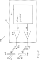
- Figure 1 depicts a first exemplary embodiment of a sensor 3 according to the present invention.
- the sensor 3 of Figure 1 is an object detection sensor that provides a single free-beam surveillance channel SVC.
- the sensor 3 is configured to generate a clearance signal CS if the free-beam surveillance channel SVC is uninterrupted and undisturbed. If the free-beam surveillance channel SVC is interrupted, an object detection signal OS is generated. If the free-beam surveillance channel SVC is uninterrupted, but disturbed a warning signal WS is generated.
- the sensor 3 comprises a transmitter device 305 and a receiver device 306.
- the transmitter device 305 comprises a first radiation emitter Tx1 and a second radiation emitter Tx2 which both are controlled by an emitter control unit 35 of the transmitter device 305.
- the radiation generated by the radiation emitters may be visible light or invisible light (e. g. infrared or ultraviolet light) or any other electromagnetic radiation.
- the emitter control unit 35 controls the first radiation emitter Tx1 such that the first radiation emitter Tx1 generates a first radiation beam B1 that conveys a first stream SBI1 of information ("first stream of data").
- the emitter control unit 35 controls the second radiation emitter Tx2 such that the second radiation emitter Tx2 generates a second radiation beam B2 that conveys a second stream SBI2 of information ("second stream of data").
- the first beam B1 and its allocated first stream SBI1 of information as well as the second beam B2 and its allocated second stream SBI2 of information are transmitted towards the reveiver unit 306 via free-space beam propagation.
- the first stream SBI1 of information and the second stream SBI2 of information are inverse.
- "inverse" means that the sub-channels SUB1 and SUB2 convey logically opposite information. For instance, when the first sub-channel SUB1 conveys the information "ACTIVE”, the second sub-channel SUB2 conveys the information "INACTIVE".
- An information can be transmitted via a single bit. Alternatively, the information and the opposite (inverse) information can be transmitted via pre-defined sequences of bits that differ from one another.
- the receiver device 306 comprises a first detector Rx1 and a second detector Rx2.
- the first radiation emitter Tx1 is individually assigned to the first detector Rx1 such that the first radiation emitter Tx1 and the first detector Rx1 form a first sub-channel SUB1 of the surveillance channel SVC.
- the second radiation emitter Tx2 is individually assigned to the second detector Rx2 such that the second radiation emitter Tx2 and the second detector Rx2 form a second sub-channel SUB2 of the surveillance channel SVC.
- An evaluation unit 36 of the receiver device 306 is configured to evaluate detection signals DS1 and DS2 of the detectors Rx1 and Rx2.
- the evaluation unit 36 generates the warning signal WS if the detection signal DS1 of the first detector Rx1 is not inverse or not sufficiently inverse - according to a predefined deviation limit - with respect to the detection signal DS2 of the second detector Rx2.
- the predefined deviation limit may for instance require that the percentage of received pairs of information (e.g. bits) that are not inverse (relatively with respect to one another) must be lower than a given maximum limit (e.g. 1%). Alternatively or additionally, the predefined deviation limit may require that the percentage of received pairs of information (e.g. bits) that are inverse must exceed a given minimum limit (e.g. 99%).
- the evaluation unit 36 generates a clearance signal CS if the free-beam surveillance channel SVC is both uninterrupted and undisturbed.
- the surveillance channel SVC may be deemed uninterrupted if both detectors Rx1 and Rx2 receive radiation and generate detection signals that have a sufficient signal strength (e.g. minimal amplitude).
- the surveillance channel SVC may be deemed undisturbed if the detections signals DS1 and DS2 and the streams SBI1 and SBI2 of information contained therein are inverse or at least sufficiently inverse according to said predefined deviation limit.
- the evaluation unit 36 generates the object detection signal OS if one or both of the sub-channels SUB1 and/or SUB2 of the free-beam surveillance channel SVC are interrupted.
- the sub-channels SUB1 and SUB2 may be deemed interrupted if the detectors Rx1 and Rx2 do not generate a sufficient detection signal, e.g. do not provide a detection signal having a required minimum amplitude.
- the radiation beams B1 and B2 emitted by the transmitter device 305 travel through a medium 311, where undesired interference may be added in terms of ambient light as well as interference of other devices operating nearby.
- the transmitter device 305 may comprise polarization filters 303 and 304 that are placed at the output ports of the radiation emitters Tx1 and Tx2.
- the polarization filters 303 and 304 are preferably oriented in such a way that the first beam B1 only comprises light that is polarized in horizontal direction (H-polarization) and the second beam B2 only comprises light that is polarized in vertical direction (V-polarization).
- the receiver device 306 comprises polarization filters 309 and 310 that are placed at the input ports of the detectors Rx1 and Rx2.
- the polarization filters 309 and 310 are preferably oriented in such a way that the first detector Rx1 only receives light that is polarized in horizontal direction (H-polarization) and the second detector Rx2 only receives light that is polarized in vertical direction (V-polarization).
- Such orientations of the polarization filters 303, 304, 309 and 310 allow conveying polar signals (+1/-1) through an optical system which per se is not capable of conveying negative polarities (we can only send 0,+1 through optical systems).
- the streams SBI1 and SBI2 of information may be sent through frequency shift keying, whereby the radiation beams B1 and B2 emitted by the radiation emitters Tx1 and Tx2 have vastly different frequencies, e.g. emit red and infra-red light.
- Appropriate optical filters may be applied to the detectors Rx1 and Rx2 to suppress cross talk between the two sub-channels SUB1 and SUB2.
- Time domain multiplexing may also (or alternatively) be used to reduce the influence of ambient light and/or interference.
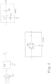
- FIG 2 shows an exemplary embodiment of a transmitter device 305 that can be incorporated in the sensor 3 of Figure 1 .
- the transmitter device 305 comprises a microprocessor 201 that may be used to generate two sequences x1 and x2, in such a way that only one sequence has a "1" or “ON” at a time (and the other has a "0" or “OFF” at the same time).
- the two digital sequences are passed through amplifiers 202 and 203 so that we have enough power for light emitting diodes (LEDs), as shown by 204 and 205, to illuminate an area of interest.
- 206 represents a horizontal polarizing filter
- 207 represents a vertical polarization filter.
- the main idea is that the sequence x1, converted to light signal will have horizontal polarization while the other sequence signal x2 will have vertical polarization.
- the microprocessor 201 and the amplifiers 202 and 203 form the emitter control unit 35 of Figure 1
- the diodes 204 and 205 form the radiation emitters Tx1 and Tx2 of Figure 1 .
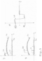
- Figure 3 shows a potential code that can be sent over to the receiver device 306, versus time t.
- a bipolar signal BPS is converted to two unipolar signals, labeled H and V. These two unipolar signals H and V form the signals x1 and x2, shown in Figure 2 .
- the unipolar signal H may be optically transmitted via the horizontally polarized beam B1 in Figure 1
- the unipolar signal V may be optically transmitted via the vertically polarized beam B2 in Figure 1 .
- FIG 4 shows an exemplary embodiment of a receiver device 306 that can be incorporated in the sensor 3 of Figure 1 .
- the received radiation beams B1 and B2 are split into horizontal and vertical polarized components, by help of a horizontal polarizing filter 101 and a vertical polarizing filter 102.
- the focused light (lens not shown for simplicity) then falls on to a photodiode 103, passing through polarization filter 101, to generate a signal y1.
- a signal y2 by passing the light through a vertical polarization filter 102, subsequently falling on to a photodiode 104.
- a differential amplifier 107 an amplification and filtering block 108, an analog to digital converter 109 and a microprocessor 110 form the evaluation unit 36 of Figure 1 .
- the diodes 103 and 104 form the radiation detectors Rx1 and Rx2 of Figure 1 .
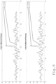
- the received signals y1 and y2 are shown in Figure 5 for one example scenario where we send "1 0 0 0" on H channel and "0 1 0 0" on V-channel. There is a phase offset of one period between the signal of the two channels. 401 represents ambient light, with ⁇ 2 ⁇ 0.5 in above equation (2).
- the thermal noise for each receiver 402 and 403 will be different but with comparable power, given by ⁇ 2 ti.
- 406 and 407 represent the combined signals, given by y1 and y2 respectively.
- the received voltage levels +V (409) and -V (410), in practice will be too small and will need to be amplified and passed through a high pass filter to reduce the thermal noise. This is achieved by the amplification and filtering block 108. In the end, the signal is sampled through analog to digital converter 109.
- the receiver device 306 of Figures 1 and 4 may have a lens 601 that focuses the incident light on a beam-splitter 602 and the output H and V channels are processed as depicted in Figure 6 .
- a beam-splitter mechanism can be realized using a partial mirror 603, a horizontal polarization filter 605 and a vertical polarization filter 604 as depicted by 602(1). It can also be realized through a polarizing cube beam-splitter 606, as shown in 602(2).
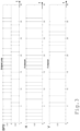
- Figure 7 depicts a second exemplary embodiment of a sensor 3 according to the present invention.
- the sensor of Figure 7 is a light curtain sensor that provides a plurality of surveillance channels SVC1-SVCn (n>1).
- Each of the surveillance channels SVC1-SVCn comprises a first and a second sub-channel SUB1 and SUB2.
- Each of the surveillance channels SVC1-SVCn may be identical with the surveillance channel SVC explained above in connection with Figure 1 .
- the first sub-channel SUB1 of each surveillance channel SVC1-SVCn is formed by a first radiation emitter Tx1 and an individually assigned first detector Rx1.
- the second sub-channel SUB2 of each surveillance channel SVC1-SVCn is formed by a second radiation emitter Tx2 and an individually assigned second detector Rx2.
- An emitter control unit 35 is configured to control the radiation emitters Tx1 and Tx2 such that each first radiation emitter Tx1 inputs a first stream SBI1 of information into its allocated sub-channel SUB1 and each second radiation emitter Tx2 inputs a second stream SBI2 of information into its allocated sub-channel SUB2.
- the first stream SBI1 of each surveillance channel is inverse to the second stream SBI2 of the same surveillance channel SVC1-SVCn.
- An evaluation unit 36 is configured to evaluate the detection signals DS1 and DS2 of the first and second detectors Rx1 and Rx2 of each of the surveillance channels SVC1-SVCn.
- the evaluation unit 36 generates a warning signal WS if the detection signal DS1 of the first detector Rx1 of at least one of the surveillance channels SVC1-SVCn and the detection signal DS2 of the corresponding second detector Rx2 of the same surveillance channel SVC1-SVCn are not inverse or not sufficiently inverse according to a predefined deviation limit.
- the warning signal WS may indicate which of the surveillance channels SVC1-SVCn is affected (disturbed).
- the predefined deviation limit may for instance require that the percentage of received pairs of information (e.g. bits) that are not inverse (relatively with respect to one another) must be lower than a given maximum limit (e.g. 1%). Alternatively or additionally, the predefined deviation limit may require that the percentage of received pairs of information (e.g. bits) that are inverse must exceed a given minimum limit (e.g. 99%).
- the evaluation unit 36 generates a clearance signal CS if all of the free-beam surveillance channels SVC1-SVCn are both uninterrupted and undisturbed.
- the surveillance channels SVC1-SVCn may be deemed uninterrupted if all detectors Rx1 and Rx2 receive radiation and generate detection signals that have a sufficient signal strength (e.g. minimal amplitude).
- the surveillance channels SVC1-SVCn may be deemed undisturbed if their detections signals DS1 and DS2 and their streams SBI1 and SBI2 of information contained therein are inverse or at least sufficiently inverse according to said predefined deviation limit.
- the evaluation unit 36 generates an object detection signal OS if at least one of the sub-channels of at least one of the free-beam surveillance channels SVC1-SVCn is interrupted.
- the sub-channels may be deemed interrupted if their allocated detectors do not generate a sufficient detection signal, e.g. do not provide a detection signal having a required minimum amplitude.
- the warning signal WS may indicate which of the surveillance channels SVC1-SVCn is interrupted.
- Each of the surveillance channels SVC1-SVCn preferably defines a surveillance segment or light curtain segment LCS of a light curtain LC generated by the light curtain sensor 3 during operation.
- the surveillance channels SVC1-SVCn may transmit the same streams SBI1 and SBI2 of information.
- the streams SBI1 and SBI2 of information may differ.
- adjacent surveillance channels transmit different streams SBI1 and SBI2 of information.
- the surveillance channels SVC1-SVCn may use radiation of the same wavelength.
- the surveillance channels SVC1-SVCn may use different wavelengths.
- adjacent surveillance channels use different wavelengths.
- a sensor 3 provides at least two different types of surveillance channels labeled A and B. Both types may have identical hardware but may differ for example with respect to the codes assigned to them, with type A using one code and type B using another code.
- the B-type receiver unit 505 will receive a signal from a B-type transmitter unit 503. But due to close proximity, it is possible that it can also receive signals from A-type transmitter units 507 and 508. The interference from other B-type transmitter units can be ignored due to the distance.
- PN Pseudo-Noise
- One drawback to using these codes are that the code length, N, should be increased to achieve a reasonable autocorrelation and cross-correlation response. For a small N the sidelobes of the autocorrelation function are too high and as a result it will not be able to suppress interference adequately.
- the problem is more of processing power and bandwidth as we have to send/receive N chips/bits in a specific time, which based on the application, can be as low as 10s of microseconds. This can increase the cost of the sensor substantially.
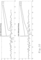
- Figure 9 shows the correlation of two such orthogonal codes A and B.
- the symbol A ⁇ B represent cross-correlation (e. g. as described in the publication " Code inverse filtering for complete side-lobe removal in phase coded pulse compression systems" (C. Daniels and V. Gregers-Hansen, IEEE International Radar Conference, 2005., Arlington, VA, 2005, pp. 256-261, doi: 10.1109/RADAR.2005.1435830 ) given by the following equation:
- the resultant vectors x ⁇ and ⁇ will be orthogonal to y and x respectively.
Landscapes
- Physics & Mathematics (AREA)
- Life Sciences & Earth Sciences (AREA)
- General Life Sciences & Earth Sciences (AREA)
- General Physics & Mathematics (AREA)
- Geophysics (AREA)
- Geophysics And Detection Of Objects (AREA)
- Optical Communication System (AREA)
Claims (13)
- Sensor (3), der mindestens einen Überwachungskanal (SVC) bereitstellt, der einen ersten und einen zweiten Unterkanal (SUB1, SUB2) umfasst,- wobei der erste Unterkanal (SUB1) durch einen ersten Strahlungssender (Tx1) und einen einzeln zugewiesenen ersten Detektor (Rx1) gebildet ist,- der zweite Unterkanal (SUB2) durch einen zweiten Strahlungssender (Tx2) und einen einzeln zugewiesenen zweiten Detektor (Rx2) gebildet ist,- eine Sendersteuereinheit (35) konfiguriert ist, die Strahlungssender derart zu steuern, dass der erste Strahlungssender (Tx1) einen ersten Strom (SBI1) von Informationen in seinen zugewiesenen Unterkanal (SUB1) eingibt und der zweite Strahlungssender (Tx2) einen zweiten Strom (SBI2) von Informationen in seinen zugewiesenen Unterkanal (SUB2) eingibt,- eine Bewertungseinheit (36) konfiguriert ist, ein Objektdetektionssignal (OS) zu erzeugen, falls der erste und/oder der zweite Strom unterbrochen sind, und- der erste Strom (SBI1) zum zweiten Strom (SBI2) logisch invers ist, derart, dass die Unterkanäle logisch entgegengesetzte Informationen transportieren, dadurch gekennzeichnet, dass die Bewertungseinheit (36) konfiguriert ist, Detektionssignale des ersten und des zweiten Detektors (Rx1, Rx2) zu bewerten und ein Warnsignal (WS) zu erzeugen, falls das Detektionssignal des ersten Detektors (Rx1) in Bezug auf das Detektionssignal des zweiten Detektors (Rx2) nicht logisch invers ist.
- Sensor (3) nach Anspruch 1,
wobei die Bewertungseinheit (36) ein Freigabesignal (CS) erzeugt, falls- der erste Detektor (Rx1) den ersten Strom (SBI1) von Informationen empfängt,- der zweite Detektor (Rx2) den zweiten Strom (SBI2) von Informationen empfängt und- der detektierte erste Strom (SBI1) und der detektierte zweite Strom (SBI2) logisch invers sind. - Sensor (3) nach einem der vorhergehenden Ansprüche,- wobei der Sensor (3) mehrere Überwachungskanäle (SVC) bereitstellt,- jeder der Überwachungskanäle (SVC) einen ersten und einen zweiten Unterkanal (SUB1, SUB2) umfasst,- der erste Unterkanal (SUB1) jedes Überwachungskanals (SVC) durch einen ersten Strahlungssender (Tx1) und einen einzeln zugewiesenen ersten Detektor (Rx1) gebildet ist,- der zweite Unterkanal (SUB2) jedes Überwachungskanals (SVC) durch einen zweiten Strahlungssender (Tx2) und einen einzeln zugewiesenen zweiten Detektor (Rx2) gebildet ist,- die Sendersteuereinheit (35) konfiguriert ist, die Strahlungssender derart zu steuern, dass jeder erste Strahlungssender (Tx1) einen ersten Strom (SBI1) von Informationen in seinen zugewiesenen Unterkanal (SUB1) eingibt und jeder zweite Strahlungssender (Tx2) einen zweiten Strom (SBI2) von Informationen in seinen zugewiesenen Unterkanal (SUB1) eingibt, wobei der erste Strom (SBI1) jedes Überwachungskanals (SVC) zum zweiten Strom (SBI2) desselben Überwachungskanals (SVC) invers ist, und- die Bewertungseinheit (36) konfiguriert ist, die Detektionssignale des ersten und des zweiten Detektors (Rx1, Rx2) jedes der Überwachungskanäle (SVC) zu bewerten und ein Warnsignal (WS) zu erzeugen, falls das Detektionssignal des ersten Detektors (Rx1) mindestens eines der Überwachungskanäle (SVC) und das Detektionssignal des entsprechenden zweiten Detektors (Rx2) desselben Überwachungskanals (SVC) nicht logisch invers sind.
- Sensor (3) nach Anspruch 3,
wobei der Sensor (3) ein Lichtvorhangsensor (3) ist. - Sensor (3) nach einem der vorhergehenden Ansprüche, wobei jeder der Überwachungskanäle (SVC) ein Überwachungssegment eines Lichtvorhangs definiert, der durch den Lichtvorhangsensor (3) während des Betriebs erzeugt wird.
- Sensor (3) nach einem der vorhergehenden Ansprüche, wobei die Bewertungseinheit (36) ein Freigabesignal (CS) erzeugt, falls der erste und der zweite Detektor (Rx1, Rx2) aller Überwachungskanäle (SVC) paarweise logisch inverse Ströme detektieren.
- Sensor (3) nach einem der vorhergehenden Ansprüche, wobei die Bewertungseinheit (36) ein Objektdetektionssignal (OS) erzeugt, falls mindestens ein Strom (SBI1) mindestens eines der Überwachungskanäle (SVC) unterbrochen ist.
- Sensor (3) nach einem der vorhergehenden Ansprüche,- wobei die Strahlung, die durch den ersten Strahlungssender (Tx1) jedes Überwachungskanals (SVC) erzeugt wird, eine erste Polarisation aufweist,- die Strahlung, die durch den zweiten Strahlungssender (Tx2) jedes Überwachungskanals (SVC) erzeugt wird, eine zweite Polarisation aufweist und- die erste Polarisation in Bezug auf die zweite Polarisation angewinkelt, zum Beispiel vertikal orientiert, ist, wobei die verschieden orientierten Polarisationen die Trennung der Unterkanäle (SUB1, SUB2) beim Ende jedes Überwachungskanals (SVC) ermöglichen.
- Sensor (3) nach einem der vorhergehenden Ansprüche, wobei die Sendersteuereinheit (35) konfiguriert ist, die Strahlungssender derart zu steuern, dass der erste und der zweite Unterkanal (SUB1, SUB2) paarweise orthogonale Codes transportieren, wobei die orthogonalen Codes die Trennung der Unterkanäle beim Ende jedes Überwachungskanals (SVC) ermöglichen.
- Sensor (3) nach einem der vorhergehenden Ansprüche,- wobei die Strahlung, die durch den ersten Strahlungssender (Tx1) jedes Überwachungskanals (SVC) erzeugt wird, eine erste Wellenlänge oder einen ersten Bereich von Wellenlängen aufweist,- die Strahlung, die durch den zweiten Strahlungssender (Tx2) jedes Überwachungskanals (SVC) erzeugt wird, eine zweite Wellenlänge oder einen zweiten Bereich von Wellenlängen aufweist und- die erste Wellenlänge oder der erste Bereich von Wellenlängen sich von der zweiten Wellenlänge oder dem zweiten Bereich von Wellenlängen unterscheidet, wobei die verschiedenen Wellenlängen oder Bereiche von Wellenlängen die Trennung der Unterkanäle beim Ende jedes Überwachungskanals (SVC) ermöglichen.
- Verfahren zum Überwachen eines Bereichs durch Bereitstellen mindestens eines Überwachungskanals (SVC), wobei
das Verfahren die folgenden Schritte umfasst:- Bereitstellen eines ersten und eines zweiten Unterkanals (SUB1, SUB2) für jeden Überwachungskanal (SVC),- wobei der erste Unterkanal (SUB1) durch einen ersten Strahlungssender (Tx1) und einen einzeln zugewiesenen ersten Detektor (Rx1) gebildet ist und- der zweite Unterkanal (SUB2) durch einen zweiten Strahlungssender (Tx2) und einen einzeln zugewiesenen zweiten Detektor (Rx2) gebildet ist, und- Steuern der Strahlungssender derart, dass der erste Strahlungssender (Tx1) einen ersten Strom (SBI1) von Informationen in seinen zugewiesenen Unterkanal (SUB1) eingibt und der zweite Strahlungssender (Tx2) einen zweiten Strom (SBI2) von Informationen in seinen zugewiesenen Unterkanal (SUB2) eingibt,- wobei der erste Strom (SBI1) zum zweiten Strom (SBI2) logisch invers ist und die Unterkanäle logisch entgegengesetzte Informationen transportieren und- ein Objektdetektionssignal (OS) erzeugt wird, falls mindestens ein Strom mindestens eines der Überwachungskanäle (SVC) unterbrochen ist, dadurch gekennzeichnet, dass Detektionssignale des ersten und des zweiten Detektors bewertet werden und ein Warnsignal (WS) erzeugt wird, falls das Detektionssignal des ersten Detektors (Rx1) in Bezug auf das Detektionssignal des zweiten Detektors (Rx2) nicht logisch invers ist. - Verfahren nach Anspruch 11,
wobei durch Bereitstellen von mehreren Überwachungskanälen (SVC) ein Lichtvorhang erzeugt wird. - Verfahren nach einem der vorhergehenden Ansprüche 11-12,
wobei ein Freigabesignal (CS) erzeugt wird, falls der erste und der zweite Detektor aller Überwachungskanäle (SVC) paarweise logisch inverse Ströme detektieren.
Priority Applications (2)
| Application Number | Priority Date | Filing Date | Title |
|---|---|---|---|
| EP21203157.9A EP4166993B1 (de) | 2021-10-18 | 2021-10-18 | Sensor zur bereitstellung eines überwachungsbereichs |
| EP22197414.0A EP4166994B1 (de) | 2021-10-18 | 2022-09-23 | Sensor zum überwachen eines bereichs |
Applications Claiming Priority (1)
| Application Number | Priority Date | Filing Date | Title |
|---|---|---|---|
| EP21203157.9A EP4166993B1 (de) | 2021-10-18 | 2021-10-18 | Sensor zur bereitstellung eines überwachungsbereichs |
Publications (3)
| Publication Number | Publication Date |
|---|---|
| EP4166993A1 EP4166993A1 (de) | 2023-04-19 |
| EP4166993C0 EP4166993C0 (de) | 2024-08-07 |
| EP4166993B1 true EP4166993B1 (de) | 2024-08-07 |
Family
ID=78676263
Family Applications (2)
| Application Number | Title | Priority Date | Filing Date |
|---|---|---|---|
| EP21203157.9A Active EP4166993B1 (de) | 2021-10-18 | 2021-10-18 | Sensor zur bereitstellung eines überwachungsbereichs |
| EP22197414.0A Active EP4166994B1 (de) | 2021-10-18 | 2022-09-23 | Sensor zum überwachen eines bereichs |
Family Applications After (1)
| Application Number | Title | Priority Date | Filing Date |
|---|---|---|---|
| EP22197414.0A Active EP4166994B1 (de) | 2021-10-18 | 2022-09-23 | Sensor zum überwachen eines bereichs |
Country Status (1)
| Country | Link |
|---|---|
| EP (2) | EP4166993B1 (de) |
Family Cites Families (7)
| Publication number | Priority date | Publication date | Assignee | Title |
|---|---|---|---|---|
| US4650990A (en) * | 1984-08-16 | 1987-03-17 | Joensson Nils | Processor-controlled light screen wherein light beam carries coded signals |
| US4847488A (en) * | 1987-12-23 | 1989-07-11 | Cerberus Ag | Sabotage resistant light barrier wherein radiation is polarized into two opposite types of polarization |
| EP2012144B1 (de) * | 2007-07-05 | 2012-01-11 | Sick Ag | Lichtgitter und Verfahren zum Betrieb eines Lichtgitters |
| DE102008009180A1 (de) * | 2007-07-10 | 2009-01-22 | Sick Ag | Optoelektronischer Sensor |
| DE202012105043U1 (de) * | 2012-12-21 | 2014-03-31 | Sick Ag | Entfernungsmessender optoelektronischer Sensor zur Erfassung und Abstandsbestimmung von Objekten |
| CN203877712U (zh) | 2014-03-28 | 2014-10-15 | 宁波赛福特电子有限公司 | 一种可拆解式光幕 |
| WO2019173898A1 (en) * | 2018-03-15 | 2019-09-19 | Metrio Sensors Inc. | System, apparatus, and method for improving performance of imaging lidar systems |
-
2021
- 2021-10-18 EP EP21203157.9A patent/EP4166993B1/de active Active
-
2022
- 2022-09-23 EP EP22197414.0A patent/EP4166994B1/de active Active
Also Published As
| Publication number | Publication date |
|---|---|
| EP4166994A1 (de) | 2023-04-19 |
| EP4166993C0 (de) | 2024-08-07 |
| EP4166993A1 (de) | 2023-04-19 |
| EP4166994B1 (de) | 2024-07-24 |
| EP4166994C0 (de) | 2024-07-24 |
Similar Documents
| Publication | Publication Date | Title |
|---|---|---|
| US5710424A (en) | Multiple field of view detector with background cancellation | |
| US5015840B1 (en) | Self-checking light curtain system and method of operation. | |
| AU2011201987B2 (en) | Amplification of interleaved optical signals | |
| ATE417286T1 (de) | Detektion eines elektromagnetischen signals | |
| SE0104099D0 (sv) | Anordning och förfarande för inriktning av komponenter | |
| JP6933114B2 (ja) | 単一光子検出装置及び量子鍵配送用受信装置 | |
| CN111896127A (zh) | 基于单光子探测器的延时多通道光子计数接收方法和系统 | |
| EP4166993B1 (de) | Sensor zur bereitstellung eines überwachungsbereichs | |
| US20080212970A1 (en) | Non-line of sight optical communications | |
| US20030116699A1 (en) | Photoelectric proximity switch | |
| US10187146B2 (en) | Light converting device | |
| NL193600C (nl) | Digitaal gegevenstransmissiestelsel. | |
| Biagi et al. | Analysis and demonstration of quasi trace orthogonal space time block coding for visible light communications | |
| ES2072417T3 (es) | Dispositivo lidar de fluorescencia diferencial y metodo de deteccion asociado. | |
| US10003408B2 (en) | Receiving method and receiver device for a coherent optical communication system | |
| US4994692A (en) | Quantizer system | |
| Costanzo et al. | A noise mitigation approach for VLC systems | |
| CN112821957A (zh) | 一种信号调制方法、解调方法及光通信系统 | |
| EP0577687A1 (de) | Verfahren und anordnung zum identifikation | |
| US20220099812A1 (en) | Systems and methods for light detection in lidar systems | |
| Guerci et al. | Adaptive transmission radar: the next" wave"? | |
| US20140212141A1 (en) | Light output apparatus and method | |
| US20250219741A1 (en) | Photoreceiver circuit, photodetector, photodetector array and optical receiver unit | |
| CN111896126B (zh) | 一种光路延时编码方法和编码系统 | |
| CN113805270B (zh) | 一种高集成度的硅光芯片 |
Legal Events
| Date | Code | Title | Description |
|---|---|---|---|
| PUAI | Public reference made under article 153(3) epc to a published international application that has entered the european phase |
Free format text: ORIGINAL CODE: 0009012 |
|
| STAA | Information on the status of an ep patent application or granted ep patent |
Free format text: STATUS: THE APPLICATION HAS BEEN PUBLISHED |
|
| AK | Designated contracting states |
Kind code of ref document: A1 Designated state(s): AL AT BE BG CH CY CZ DE DK EE ES FI FR GB GR HR HU IE IS IT LI LT LU LV MC MK MT NL NO PL PT RO RS SE SI SK SM TR |
|
| STAA | Information on the status of an ep patent application or granted ep patent |
Free format text: STATUS: REQUEST FOR EXAMINATION WAS MADE |
|
| 17P | Request for examination filed |
Effective date: 20231017 |
|
| RBV | Designated contracting states (corrected) |
Designated state(s): AL AT BE BG CH CY CZ DE DK EE ES FI FR GB GR HR HU IE IS IT LI LT LU LV MC MK MT NL NO PL PT RO RS SE SI SK SM TR |
|
| GRAP | Despatch of communication of intention to grant a patent |
Free format text: ORIGINAL CODE: EPIDOSNIGR1 |
|
| STAA | Information on the status of an ep patent application or granted ep patent |
Free format text: STATUS: GRANT OF PATENT IS INTENDED |
|
| INTG | Intention to grant announced |
Effective date: 20240307 |
|
| GRAS | Grant fee paid |
Free format text: ORIGINAL CODE: EPIDOSNIGR3 |
|
| GRAA | (expected) grant |
Free format text: ORIGINAL CODE: 0009210 |
|
| STAA | Information on the status of an ep patent application or granted ep patent |
Free format text: STATUS: THE PATENT HAS BEEN GRANTED |
|
| AK | Designated contracting states |
Kind code of ref document: B1 Designated state(s): AL AT BE BG CH CY CZ DE DK EE ES FI FR GB GR HR HU IE IS IT LI LT LU LV MC MK MT NL NO PL PT RO RS SE SI SK SM TR |
|
| REG | Reference to a national code |
Ref country code: GB Ref legal event code: FG4D |
|
| REG | Reference to a national code |
Ref country code: CH Ref legal event code: EP |
|
| REG | Reference to a national code |
Ref country code: IE Ref legal event code: FG4D |
|
| REG | Reference to a national code |
Ref country code: DE Ref legal event code: R096 Ref document number: 602021016737 Country of ref document: DE |
|
| U01 | Request for unitary effect filed |
Effective date: 20240829 |
|
| U07 | Unitary effect registered |
Designated state(s): AT BE BG DE DK EE FI FR IT LT LU LV MT NL PT RO SE SI Effective date: 20240910 |
|
| U20 | Renewal fee for the european patent with unitary effect paid |
Year of fee payment: 4 Effective date: 20241030 |
|
| PG25 | Lapsed in a contracting state [announced via postgrant information from national office to epo] |
Ref country code: NO Free format text: LAPSE BECAUSE OF FAILURE TO SUBMIT A TRANSLATION OF THE DESCRIPTION OR TO PAY THE FEE WITHIN THE PRESCRIBED TIME-LIMIT Effective date: 20241107 |
|
| PG25 | Lapsed in a contracting state [announced via postgrant information from national office to epo] |
Ref country code: GR Free format text: LAPSE BECAUSE OF FAILURE TO SUBMIT A TRANSLATION OF THE DESCRIPTION OR TO PAY THE FEE WITHIN THE PRESCRIBED TIME-LIMIT Effective date: 20241108 Ref country code: PL Free format text: LAPSE BECAUSE OF FAILURE TO SUBMIT A TRANSLATION OF THE DESCRIPTION OR TO PAY THE FEE WITHIN THE PRESCRIBED TIME-LIMIT Effective date: 20240807 |
|
| PG25 | Lapsed in a contracting state [announced via postgrant information from national office to epo] |
Ref country code: IS Free format text: LAPSE BECAUSE OF FAILURE TO SUBMIT A TRANSLATION OF THE DESCRIPTION OR TO PAY THE FEE WITHIN THE PRESCRIBED TIME-LIMIT Effective date: 20241207 |
|
| PG25 | Lapsed in a contracting state [announced via postgrant information from national office to epo] |
Ref country code: HR Free format text: LAPSE BECAUSE OF FAILURE TO SUBMIT A TRANSLATION OF THE DESCRIPTION OR TO PAY THE FEE WITHIN THE PRESCRIBED TIME-LIMIT Effective date: 20240807 |
|
| PG25 | Lapsed in a contracting state [announced via postgrant information from national office to epo] |
Ref country code: RS Free format text: LAPSE BECAUSE OF FAILURE TO SUBMIT A TRANSLATION OF THE DESCRIPTION OR TO PAY THE FEE WITHIN THE PRESCRIBED TIME-LIMIT Effective date: 20241107 Ref country code: ES Free format text: LAPSE BECAUSE OF FAILURE TO SUBMIT A TRANSLATION OF THE DESCRIPTION OR TO PAY THE FEE WITHIN THE PRESCRIBED TIME-LIMIT Effective date: 20240807 |
|
| PG25 | Lapsed in a contracting state [announced via postgrant information from national office to epo] |
Ref country code: RS Free format text: LAPSE BECAUSE OF FAILURE TO SUBMIT A TRANSLATION OF THE DESCRIPTION OR TO PAY THE FEE WITHIN THE PRESCRIBED TIME-LIMIT Effective date: 20241107 Ref country code: PL Free format text: LAPSE BECAUSE OF FAILURE TO SUBMIT A TRANSLATION OF THE DESCRIPTION OR TO PAY THE FEE WITHIN THE PRESCRIBED TIME-LIMIT Effective date: 20240807 Ref country code: NO Free format text: LAPSE BECAUSE OF FAILURE TO SUBMIT A TRANSLATION OF THE DESCRIPTION OR TO PAY THE FEE WITHIN THE PRESCRIBED TIME-LIMIT Effective date: 20241107 Ref country code: IS Free format text: LAPSE BECAUSE OF FAILURE TO SUBMIT A TRANSLATION OF THE DESCRIPTION OR TO PAY THE FEE WITHIN THE PRESCRIBED TIME-LIMIT Effective date: 20241207 Ref country code: HR Free format text: LAPSE BECAUSE OF FAILURE TO SUBMIT A TRANSLATION OF THE DESCRIPTION OR TO PAY THE FEE WITHIN THE PRESCRIBED TIME-LIMIT Effective date: 20240807 Ref country code: GR Free format text: LAPSE BECAUSE OF FAILURE TO SUBMIT A TRANSLATION OF THE DESCRIPTION OR TO PAY THE FEE WITHIN THE PRESCRIBED TIME-LIMIT Effective date: 20241108 Ref country code: ES Free format text: LAPSE BECAUSE OF FAILURE TO SUBMIT A TRANSLATION OF THE DESCRIPTION OR TO PAY THE FEE WITHIN THE PRESCRIBED TIME-LIMIT Effective date: 20240807 |
|
| PG25 | Lapsed in a contracting state [announced via postgrant information from national office to epo] |
Ref country code: SM Free format text: LAPSE BECAUSE OF FAILURE TO SUBMIT A TRANSLATION OF THE DESCRIPTION OR TO PAY THE FEE WITHIN THE PRESCRIBED TIME-LIMIT Effective date: 20240807 |
|
| PG25 | Lapsed in a contracting state [announced via postgrant information from national office to epo] |
Ref country code: CZ Free format text: LAPSE BECAUSE OF FAILURE TO SUBMIT A TRANSLATION OF THE DESCRIPTION OR TO PAY THE FEE WITHIN THE PRESCRIBED TIME-LIMIT Effective date: 20240807 |
|
| PG25 | Lapsed in a contracting state [announced via postgrant information from national office to epo] |
Ref country code: SK Free format text: LAPSE BECAUSE OF FAILURE TO SUBMIT A TRANSLATION OF THE DESCRIPTION OR TO PAY THE FEE WITHIN THE PRESCRIBED TIME-LIMIT Effective date: 20240807 |
|
| REG | Reference to a national code |
Ref country code: CH Ref legal event code: PL |
|
| PLBE | No opposition filed within time limit |
Free format text: ORIGINAL CODE: 0009261 |
|
| STAA | Information on the status of an ep patent application or granted ep patent |
Free format text: STATUS: NO OPPOSITION FILED WITHIN TIME LIMIT |
|
| PG25 | Lapsed in a contracting state [announced via postgrant information from national office to epo] |
Ref country code: MC Free format text: LAPSE BECAUSE OF FAILURE TO SUBMIT A TRANSLATION OF THE DESCRIPTION OR TO PAY THE FEE WITHIN THE PRESCRIBED TIME-LIMIT Effective date: 20240807 |
|
| 26N | No opposition filed |
Effective date: 20250508 |
|
| PG25 | Lapsed in a contracting state [announced via postgrant information from national office to epo] |
Ref country code: CH Free format text: LAPSE BECAUSE OF NON-PAYMENT OF DUE FEES Effective date: 20241031 |
|
| PG25 | Lapsed in a contracting state [announced via postgrant information from national office to epo] |
Ref country code: IE Free format text: LAPSE BECAUSE OF NON-PAYMENT OF DUE FEES Effective date: 20241018 |
|
| U20 | Renewal fee for the european patent with unitary effect paid |
Year of fee payment: 5 Effective date: 20251027 |
|
| PG25 | Lapsed in a contracting state [announced via postgrant information from national office to epo] |
Ref country code: CY Free format text: LAPSE BECAUSE OF FAILURE TO SUBMIT A TRANSLATION OF THE DESCRIPTION OR TO PAY THE FEE WITHIN THE PRESCRIBED TIME-LIMIT; INVALID AB INITIO Effective date: 20211018 |
|
| PG25 | Lapsed in a contracting state [announced via postgrant information from national office to epo] |
Ref country code: HU Free format text: LAPSE BECAUSE OF FAILURE TO SUBMIT A TRANSLATION OF THE DESCRIPTION OR TO PAY THE FEE WITHIN THE PRESCRIBED TIME-LIMIT; INVALID AB INITIO Effective date: 20211018 |