EP4166962A1 - Elektrischer energiespeicher - Google Patents
Elektrischer energiespeicher Download PDFInfo
- Publication number
- EP4166962A1 EP4166962A1 EP21202939.1A EP21202939A EP4166962A1 EP 4166962 A1 EP4166962 A1 EP 4166962A1 EP 21202939 A EP21202939 A EP 21202939A EP 4166962 A1 EP4166962 A1 EP 4166962A1
- Authority
- EP
- European Patent Office
- Prior art keywords
- measuring
- switching means
- energy storage
- balancing
- storage cells
- Prior art date
- Legal status (The legal status is an assumption and is not a legal conclusion. Google has not performed a legal analysis and makes no representation as to the accuracy of the status listed.)
- Granted
Links
Images




Classifications
-
- G—PHYSICS
- G01—MEASURING; TESTING
- G01R—MEASURING ELECTRIC VARIABLES; MEASURING MAGNETIC VARIABLES
- G01R31/00—Arrangements for testing electric properties; Arrangements for locating electric faults; Arrangements for electrical testing characterised by what is being tested not provided for elsewhere
- G01R31/36—Arrangements for testing, measuring or monitoring the electrical condition of accumulators or electric batteries, e.g. capacity or state of charge [SoC]
- G01R31/396—Acquisition or processing of data for testing or for monitoring individual cells or groups of cells within a battery
-
- B—PERFORMING OPERATIONS; TRANSPORTING
- B60—VEHICLES IN GENERAL
- B60L—PROPULSION OF ELECTRICALLY-PROPELLED VEHICLES; SUPPLYING ELECTRIC POWER FOR AUXILIARY EQUIPMENT OF ELECTRICALLY-PROPELLED VEHICLES; ELECTRODYNAMIC BRAKE SYSTEMS FOR VEHICLES IN GENERAL; MAGNETIC SUSPENSION OR LEVITATION FOR VEHICLES; MONITORING OPERATING VARIABLES OF ELECTRICALLY-PROPELLED VEHICLES; ELECTRIC SAFETY DEVICES FOR ELECTRICALLY-PROPELLED VEHICLES
- B60L58/00—Methods or circuit arrangements for monitoring or controlling batteries or fuel cells, specially adapted for electric vehicles
- B60L58/10—Methods or circuit arrangements for monitoring or controlling batteries or fuel cells, specially adapted for electric vehicles for monitoring or controlling batteries
-
- B—PERFORMING OPERATIONS; TRANSPORTING
- B60—VEHICLES IN GENERAL
- B60L—PROPULSION OF ELECTRICALLY-PROPELLED VEHICLES; SUPPLYING ELECTRIC POWER FOR AUXILIARY EQUIPMENT OF ELECTRICALLY-PROPELLED VEHICLES; ELECTRODYNAMIC BRAKE SYSTEMS FOR VEHICLES IN GENERAL; MAGNETIC SUSPENSION OR LEVITATION FOR VEHICLES; MONITORING OPERATING VARIABLES OF ELECTRICALLY-PROPELLED VEHICLES; ELECTRIC SAFETY DEVICES FOR ELECTRICALLY-PROPELLED VEHICLES
- B60L58/00—Methods or circuit arrangements for monitoring or controlling batteries or fuel cells, specially adapted for electric vehicles
- B60L58/10—Methods or circuit arrangements for monitoring or controlling batteries or fuel cells, specially adapted for electric vehicles for monitoring or controlling batteries
- B60L58/18—Methods or circuit arrangements for monitoring or controlling batteries or fuel cells, specially adapted for electric vehicles for monitoring or controlling batteries of two or more battery modules
- B60L58/21—Methods or circuit arrangements for monitoring or controlling batteries or fuel cells, specially adapted for electric vehicles for monitoring or controlling batteries of two or more battery modules having the same nominal voltage
-
- G—PHYSICS
- G01—MEASURING; TESTING
- G01R—MEASURING ELECTRIC VARIABLES; MEASURING MAGNETIC VARIABLES
- G01R31/00—Arrangements for testing electric properties; Arrangements for locating electric faults; Arrangements for electrical testing characterised by what is being tested not provided for elsewhere
- G01R31/36—Arrangements for testing, measuring or monitoring the electrical condition of accumulators or electric batteries, e.g. capacity or state of charge [SoC]
- G01R31/382—Arrangements for monitoring battery or accumulator variables, e.g. SoC
- G01R31/3835—Arrangements for monitoring battery or accumulator variables, e.g. SoC involving only voltage measurements
-
- B—PERFORMING OPERATIONS; TRANSPORTING
- B60—VEHICLES IN GENERAL
- B60L—PROPULSION OF ELECTRICALLY-PROPELLED VEHICLES; SUPPLYING ELECTRIC POWER FOR AUXILIARY EQUIPMENT OF ELECTRICALLY-PROPELLED VEHICLES; ELECTRODYNAMIC BRAKE SYSTEMS FOR VEHICLES IN GENERAL; MAGNETIC SUSPENSION OR LEVITATION FOR VEHICLES; MONITORING OPERATING VARIABLES OF ELECTRICALLY-PROPELLED VEHICLES; ELECTRIC SAFETY DEVICES FOR ELECTRICALLY-PROPELLED VEHICLES
- B60L2240/00—Control parameters of input or output; Target parameters
- B60L2240/40—Drive Train control parameters
- B60L2240/54—Drive Train control parameters related to batteries
- B60L2240/547—Voltage
-
- G—PHYSICS
- G01—MEASURING; TESTING
- G01R—MEASURING ELECTRIC VARIABLES; MEASURING MAGNETIC VARIABLES
- G01R31/00—Arrangements for testing electric properties; Arrangements for locating electric faults; Arrangements for electrical testing characterised by what is being tested not provided for elsewhere
- G01R31/28—Testing of electronic circuits, e.g. by signal tracer
-
- G—PHYSICS
- G01—MEASURING; TESTING
- G01R—MEASURING ELECTRIC VARIABLES; MEASURING MAGNETIC VARIABLES
- G01R31/00—Arrangements for testing electric properties; Arrangements for locating electric faults; Arrangements for electrical testing characterised by what is being tested not provided for elsewhere
- G01R31/36—Arrangements for testing, measuring or monitoring the electrical condition of accumulators or electric batteries, e.g. capacity or state of charge [SoC]
- G01R31/385—Arrangements for measuring battery or accumulator variables
- G01R31/387—Determining ampere-hour charge capacity or SoC
- G01R31/388—Determining ampere-hour charge capacity or SoC involving voltage measurements
-
- G—PHYSICS
- G01—MEASURING; TESTING
- G01R—MEASURING ELECTRIC VARIABLES; MEASURING MAGNETIC VARIABLES
- G01R31/00—Arrangements for testing electric properties; Arrangements for locating electric faults; Arrangements for electrical testing characterised by what is being tested not provided for elsewhere
- G01R31/50—Testing of electric apparatus, lines, cables or components for short-circuits, continuity, leakage current or incorrect line connections
- G01R31/54—Testing for continuity
Definitions
- the invention is based on the object of providing an electrical energy store which has the highest possible operational reliability.
- the electrical energy store is intended in particular for use with a hand-held power tool, such as a chain saw, a hedge trimmer, a leaf blower or the like.
- the electrical energy storage device conventionally has a series connection of a number n of rechargeable energy storage cells, for example in the form of accumulators or electrochemical cells.
- the number n can be between 2 and 40, for example.
- One of the energy storage cells is connected to a reference potential.
- the electrical energy store also has a series connection of a number n of measuring resistors.
- the electrical energy store also has a number n of controllable measuring switching means, for example in the form of transistors.
- a first of the number n of measuring switching means is looped in between the series circuit consisting of the number n of energy storage cells and the series circuit consisting of the number n of measuring resistors.
- the series connections are electrically connected at their upper end by means of the first measuring switching means.
- a respectively associated measuring switching means is looped in between connecting nodes of adjacent energy storage cells and connecting nodes of adjacent measuring resistors.
- the electrical energy store also has a balancing switching means, for example in the form of a transistor, which is looped in between one of the number n of measuring resistors and the reference potential.
- the electrical energy store also has a measuring unit, for example in the form of a microcontroller, which measures a voltage drop across one of the number n of measuring resistors.
- the electrical energy storage device also has a control unit, for example in the form of a microcontroller, which is designed to control the measuring switching device and the balancing switching device, depending on a switching state of the measuring switching device and the balancing switching device and the to determine a state of charge of the energy storage cells by means of the voltage measured by the measuring unit and to monitor the proper functioning of the measuring switching means.
- a control unit for example in the form of a microcontroller, which is designed to control the measuring switching device and the balancing switching device, depending on a switching state of the measuring switching device and the balancing switching device and the to determine a state of charge of the energy storage cells by means of the voltage measured by the measuring unit and to monitor the proper functioning of the measuring switching means.
- control unit and the measuring unit can be implemented jointly by a microprocessor application, for example.
- control unit is designed to sequentially control the measuring switching means and the balancing switching means to monitor the proper functioning of the measuring switching means such that an identical amount of charge is removed from each energy storage cell on a time average.
- control unit is designed to sequentially actuate the measuring switching means and the balancing switching means to determine the state of charge of the energy storage cells in such a way that an identical quantity of charge is taken from each energy storage cell on average over time.
- control unit is designed to close the balancing switch in a monitoring sequence in order to monitor the proper functioning of the measuring switching means and to close only one of the measuring switching means in successive steps until all measuring switching means are closed once and in a compensation sequence to close the first measuring switching means with the balancing switching means initially closed, then to open the balancing switching means and in successive steps to close only one of the further measuring switching means until all further measuring Switching means have been closed once, with the monitoring sequence and the compensation sequence being carried out equally often.
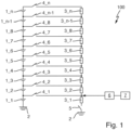
- 1 1 shows a schematic circuit diagram of an electrical energy store 100.
- the electrical energy store 100 has: a number n of energy storage cells 1_1, . . . , 1_n connected in series, with one energy storage cell 1_1 being connected to a reference potential 2.
- the electrical energy store 100 also has a series connection of a number n of measuring resistors 3_1, . . . , 3_n with identical resistance values.
- the electrical energy store 100 also has a number n of measuring switching means 4_1, ..., 4_n, with the series connection of the number n of energy storage cells 1_1, ..., 1_n and the series connection of the number n of measuring resistors 3_1, .. . , 3_n, a first measuring switching means 4_n is looped in, and between connecting nodes of adjacent energy storage cells 1_1, ..., 1_n and connecting nodes of adjacent measuring resistors 3_1, ..., 3_n there is an associated measuring switching means 4_1, ..., 4_n -1 is looped in.
- the electrical energy store 100 also has a balancing switch 5 which is looped in between a measuring resistor 3_1 and the reference potential 2 .
- the electrical energy store 100 also has a measuring unit 6, which measures a voltage drop across the measuring resistor 3_1.
- the electrical energy store 100 also has a control unit 7, which is designed to control the measuring switching means 4_1, ..., 4_n and the balancing switching means 5, depending on a switching state of the measuring switching means 4_1, ..., 4_n and the balancing switching means 5 and the voltage measured by the measuring unit 6 a state of charge to determine the energy storage cells 1_1, ..., 1_n and to monitor the proper functioning of the measuring switching means 4_1, ..., 4_n.
- a control unit 7 which is designed to control the measuring switching means 4_1, ..., 4_n and the balancing switching means 5, depending on a switching state of the measuring switching means 4_1, ..., 4_n and the balancing switching means 5 and the voltage measured by the measuring unit 6 a state of charge to determine the energy storage cells 1_1, ..., 1_n and to monitor the proper functioning of the measuring switching means 4_1, ..., 4_n.
- the Figure 2a /j show an example of a measurement cycle for determining the state of charge of the energy storage cells 1_1, ..., 1_n.
- the first or upper measuring switching device 4_n and the balancing switching device 5 remain permanently closed.
- the current contribution of the respective energy storage cells 1_1, . . . , 1_n is shown on the right.
- Figure 2a shows schematically a first step of the measurement cycle.
- the measuring switching means 4_1 is closed and the measuring switching means 4_2 to 4_n-1 are open.
- the state of charge of energy storage cell 1_1 is determined based on the voltage measured at measuring resistor 3_1.
- Figure 2b shows schematically a second step of the measurement cycle.
- the measuring switching means 4_2 is closed and the measuring switching means 4_1 and 4_3 to 4_n-1 are open.
- the state of charge of energy storage cell 1_2 is determined based on the voltage measured at measuring resistor 3_1 and the previously measured voltage.
- the measuring switching means 4_1 A respective duration of the steps of the measurement cycle is identical in this case.
- the Figure 3a /j schematically show a monitoring sequence for monitoring the proper functioning of the measuring switching means 4_1 to 4_n.
- the current contribution of the respective energy storage cells 1_1, . . . , 1_n is shown on the right.
- the balancing switching means 5 is closed and in successive steps only one of the measuring switching means 4_1, ..., 4_n-1 is closed until all measuring switching means 4_1, ..., 4_n- 1 have been closed once.
- the correct functioning of the measuring switching means 4_1, . . . , 4_n can be checked on the basis of the voltage measured at the measuring resistor 3_1.
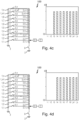
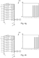
- the Figure 4a /j schematically show a compensation sequence for compensating for the asymmetric discharge of the energy storage cells 1_1, . . . , 1_n caused by the monitoring sequence. On the right is the current contribution of the respective energy storage cells 1_1, ..., 1_n shown.
- the compensation sequence as in Figure 4a shown, when the balancing switching means 5 is closed, the first measuring switching means 4_n is closed.
- the balancing switching means 5 is then permanently opened and only one of the further measuring switching means 4_1, ..., 4_n-1 is closed in successive steps until all further measuring switching means 4_1, ..., 4_n- 1 have been closed once.
- the correct functioning of the measuring switching means 4_1, . . . , 4_n can be checked on the basis of the voltage measured at the measuring resistor 3_1.
- the monitoring sequence and the compensation sequence are carried out with equal frequency, so that an identical amount of charge is taken from each energy storage cell 1_1, . . . , 1_n on average over time.
- a respective duration of the steps of the monitoring sequence is identical here and a respective duration of the steps of the compensation sequence is also identical here.
Landscapes
- Engineering & Computer Science (AREA)
- Physics & Mathematics (AREA)
- General Physics & Mathematics (AREA)
- Life Sciences & Earth Sciences (AREA)
- Sustainable Development (AREA)
- Sustainable Energy (AREA)
- Power Engineering (AREA)
- Transportation (AREA)
- Mechanical Engineering (AREA)
- Charge And Discharge Circuits For Batteries Or The Like (AREA)
- Measurement Of Current Or Voltage (AREA)
Abstract
Description
- Der Erfindung liegt die Aufgabe zugrunde, einen elektrischen Energiespeicher zur Verfügung zu stellen, der eine möglichst hohe Betriebssicherheit aufweist.
- Der elektrische Energiespeicher ist insbesondere zur Verwendung mit einem handgetragenen Elektrowerkzeug, vorgesehen, wie beispielsweise einer Kettensäge, einer Heckenschere, einem Laubbläser oder dergleichen.
- Der elektrische Energiespeicher weist herkömmlich eine Reihenschaltung einer Anzahl n von wiederaufladbaren Energiespeicherzellen auf, beispielsweise in Form von Akkumulatoren bzw. elektrochemischen Zellen. Die Anzahl n kann beispielsweise zwischen 2 und 40 betragen. Eine der Energiespeicherzellen ist mit einem Bezugspotential verbunden.
- Der elektrische Energiespeicher weist weiter eine Reihenschaltung einer Anzahl n von Messwiderständen auf.
- Der elektrische Energiespeicher weist weiter eine Anzahl n von ansteuerbaren Mess-Schaltmitteln auf, beispielsweise in Form von Transistoren.
- Zwischen die Reihenschaltung bestehend aus der Anzahl n von Energiespeicherzellen und die Reihenschaltung bestehend aus der Anzahl n von Messwiderständen ist ein erstes der Anzahl n von Mess-Schaltmitteln eingeschleift ist. Mit anderen Worten werden die Reihenschaltungen mittels des ersten Messschaltmittels an ihrem oberen Ende elektrisch verbunden.
- Zwischen Verbindungsknoten von benachbarten Energiespeicherzellen und Verbindungsnoten von benachbarten Messwiderständen ist ein jeweils zugehöriges der Mess-Schaltmittel eingeschleift.
- Der elektrische Energiespeicher weist weiter ein Symmetrier-Schaltmittel auf, beispielsweise in Form eines Transistors, das zwischen einen der Anzahl n von Messwiderständen und das Bezugspotential eingeschleift ist.
- Der elektrische Energiespeicher weist weiter eine Messeinheit auf, beispielsweise in Form eines Mikrocontrollers, die bzw. der eine an einem der Anzahl n von Messwiderständen abfallende Spannung misst.
- Der elektrische Energiespeicher weist weiter eine Steuereinheit auf, beispielsweise in Form eines Mikrocontrollers, die bzw. der dazu ausgebildet ist, die Mess-Schaltmittel und das Symmetrier-Schaltmittel anzusteuern, in Abhängigkeit von einem Schaltzustand der Mess-Schaltmittel und des Symmetrier-Schaltmittels und der mittels der Messeinheit gemessenen Spannung einen Ladezustand der Energiespeicherzellen zu ermitteln und die ordnungsgemäße Funktion der Mess-Schaltmittel zu überwachen.
- Die Steuereinheit und die Messeinheit können beispielsweise gemeinsam durch eine Mikroprozessorapplikation realisiert sein.
- In einer Ausführungsform ist die Steuereinheit dazu ausgebildet, zum Überwachen der ordnungsgemäßen Funktion der Mess-Schaltmittel die Mess-Schaltmittel und das Symmetrier-Schaltmittel derart sequenziell anzusteuern, dass in einem zeitlichen Mittel aus jeder Energiespeicherzelle eine identische Ladungsmenge entnommen wird.
- In einer Ausführungsform ist die Steuereinheit dazu ausgebildet, zum Ermitteln des Ladezustands der Energiespeicherzellen die Mess-Schaltmittel und das Symmetrier-Schaltmittel derart sequenziell anzusteuern, dass in einem zeitlichen Mittel aus jeder Energiespeicherzelle eine identische Ladungsmenge entnommen wird.
- In einer Ausführungsform ist die Steuereinheit dazu ausgebildet, zum Überwachen der ordnungsgemäßen Funktion der Mess-Schaltmittel in einer Überwachungs-Sequenz das Symmetrier-Schaltmittel zu schließen und in aufeinanderfolgenden Schritten immer nur eines der Mess-Schaltmittel zu schließen, bis alle Mess-Schaltmittel einmal geschlossen worden sind, und in einer Kompensations-Sequenz bei zunächst geschlossenem Symmetrier-Schaltmittel das erste Mess-Schaltmittel zu schließen, danach das Symmetrier-Schaltmittel zu öffnen und in aufeinanderfolgenden Schritten immer nur eines der weiteren Mess-Schaltmittel zu schließen, bis alle weiteren Mess-Schaltmittel einmal geschlossen worden sind, wobei die Überwachungs-Sequenz und die Kompensations-Sequenz gleich häufig durchgeführt werden.
- Die Erfindung wird nachfolgend unter Bezugnahme auf die Zeichnungen detailliert beschrieben. Hierbei zeigt:
- Fig. 1
- ein schematisches Schaltbild eines elektrischen Energiespeichers,
- Fig. 2a/j
- einen Messzyklus zum Ermitteln eines Ladezustands von Energiespeicherzel-len des in
Fig. 1 gezeigten elektrischen Energiespeichers, - Fig. 3a/j
- eine Überwachungs-Sequenz zum Überwachen der ordnungsgemäßen Funk-tion von Mess-Schaltmitteln des in
Fig. 1 gezeigten elektrischen Energiespei-chers, und - Fig. 4a/j
- eine Kompensations-Sequenz zum Kompensieren der durch die Überwa-chungs-Sequenz verursachten asymmetrischen Entladung der Energiespei-cherzellen.
-
Fig. 1 zeigt ein schematisches Schaltbild eines elektrischen Energiespeichers 100. Der elektrische Energiespeicher 100 weist auf: eine Reihenschaltung einer Anzahl n von Energiespeicherzellen 1_1, ..., 1_n, wobei eine Energiespeicherzelle 1_1 mit einem Bezugspotential 2 verbunden ist. - Der elektrische Energiespeicher 100 weist weiter eine Reihenschaltung einer Anzahl n von Messwiderständen 3_1, ..., 3_n mit identischen Widerstandswerten auf.
- Der elektrische Energiespeicher 100 weist weiter eine Anzahl n von Mess-Schaltmitteln 4_1, ..., 4_n auf, wobei zwischen die Reihenschaltung der Anzahl n von Energiespeicherzellen 1_1, ..., 1_n und die Reihenschaltung der Anzahl n von Messwiderständen 3_1, ..., 3_n ein erstes Mess-Schaltmittel 4_n eingeschleift ist und wobei zwischen Verbindungsknoten von benachbarten Energiespeicherzellen 1_1, ..., 1_n und Verbindungsnoten von benachbarten Messwiderständen 3_1, ..., 3_n ein jeweils zugehöriges Mess-Schaltmittel 4_1, ..., 4_n-1 eingeschleift ist.
- Der elektrische Energiespeicher 100 weist weiter ein Symmetrier-Schaltmittel 5 auf, das zwischen einen Messwiderstand 3_1 und das Bezugspotential 2 eingeschleift ist.
- Der elektrische Energiespeicher 100 weist weiter eine Messeinheit 6 auf, die eine an dem Messwiderstand 3_1 abfallende Spannung misst.
- Der elektrische Energiespeicher 100 weist weiter eine Steuereinheit 7 auf, die dazu ausgebildet ist, die Mess-Schaltmittel 4_1, ..., 4_n und das Symmetrier-Schaltmittel 5 anzusteuern, in Abhängigkeit von einem Schaltzustand der Mess-Schaltmittel 4_1, ..., 4_n und des Symmetrier-Schaltmittels 5 und der mittels der Messeinheit 6 gemessenen Spannung einen Ladezustand der Energiespeicherzellen 1_1, ..., 1_n zu ermitteln und die ordnungsgemäße Funktion der Mess-Schaltmittel 4_1, ..., 4_n zu überwachen.
- Die
Fig. 2a /j zeigen exemplarisch einen Messzyklus zum Ermitteln des Ladezustands der Energiespeicherzellen 1_1, ..., 1_n. Im Messzyklus bleiben das erste bzw. obere Mess-Schaltmittel 4_n und das Symmetrier-Schaltmittel 5 dauerhaft geschlossen. Rechts ist jeweils der Strombeitrag der jeweiligen Energiespeicherzellen 1_1, ..., 1_n dargestellt. -
Fig. 2a zeigt schematisch einen ersten Schritt des Messzyklus. Hierbei ist das Mess-Schaltmittel 4_1 geschlossen und die Mess-Schaltmittel 4_2 bis 4_n-1 sind geöffnet. Basierend auf der am Mess-Widerstand 3_1 gemessenen Spannung wird der Ladezustand der Energiespeicherzelle 1_1 ermittelt. -
Fig. 2b zeigt schematisch einen zweiten Schritt des Messzyklus. Hierbei ist das Mess-Schaltmittel 4_2 geschlossen und die Mess-Schaltmittel 4_1 und 4_3 bis 4_n-1 sind geöffnet. Basierend auf der am Mess-Widerstand 3_1 gemessenen Spannung und der zuvor gemessenen Spannung wird der Ladezustand der Energiespeicherzelle 1_2 ermittelt. - Die
Figuren 2c bis 2j zeigen nun die weiteren Schritte des Messzyklus. - Die Mess-Schaltmittel 4_1, ..., 4_n werden folglich derart sequenziell angesteuert, dass in einem zeitlichen Mittel aus jeder Energiespeicherzelle 1_1, ..., 1_n eine identische Ladungsmenge entnommen wird. Eine jeweilige Dauer der Schritte des Messzyklus ist hierbei identisch.
- Die
Fig. 3a /j zeigen schematisch eine Überwachungs-Sequenz zum Überwachen der ordnungsgemäßen Funktion der Mess-Schaltmittel 4_1 bis 4_n. Rechts ist jeweils der Strombeitrag der jeweiligen Energiespeicherzellen 1_1, ..., 1_n dargestellt. In der Überwachungs-Sequenz ist das Symmetrier-Schaltmittel 5 geschlossen und in aufeinanderfolgenden Schritten wird immer nur eines der Mess-Schaltmittel 4_1, ..., 4_n-1 geschlossen, so lange bis alle Mess-Schaltmittel 4_1, ..., 4_n-1 einmal geschlossen worden sind. Anhand der am Mess-Widerstand 3_1 gemessenen Spannung kann die korrekte Funktion der Mess-Schaltmittel 4_1, ..., 4_n überprüft werden. - Die
Fig. 4a /j zeigen schematisch eine Kompensations-Sequenz zum Kompensieren der durch die Überwachungs-Sequenz verursachten asymmetrischen Entladung der Energiespeicherzellen 1_1, ..., 1_n. Rechts ist jeweils der Strombeitrag der jeweiligen Energiespeicherzellen 1_1, ..., 1_n dargestellt. In der Kompensations-Sequenz wird zunächst, wie inFig. 4a gezeigt, bei geschlossenem Symmetrier-Schaltmittel 5 das erste Mess-Schaltmittel 4_n geschlossen. - Bezug nehmend auf die
Figuren 4b /j wird danach das Symmetrier-Schaltmittel 5 dauerhaft geöffnet und in aufeinanderfolgenden Schritten immer nur eines der weiteren Mess-Schaltmittel 4_1, ..., 4_n-1 geschlossen, so lange bis alle weiteren Mess-Schaltmittel 4_1, ..., 4_n-1 einmal geschlossen worden sind. Anhand der am Mess-Widerstand 3_1 gemessenen Spannung kann die korrekte Funktion der Mess-Schaltmittel 4_1, ..., 4_n überprüft werden. - Die Überwachungs-Sequenz und die Kompensations-Sequenz werden gleich häufig durchgeführt, so dass in einem zeitlichen Mittel aus jeder Energiespeicherzelle 1_1, ..., 1_n eine identische Ladungsmenge entnommen wird.
- Eine jeweilige Dauer der Schritte der Überwachungs-Sequenz ist hierbei identisch und eine jeweilige Dauer der Schritte der Kompensations-Sequenz ist hierbei ebenfalls identisch.
Claims (4)
- Elektrischer Energiespeicher (100), insbesondere für ein handgetragenes Elektrowerkzeug, aufweisend:- eine Reihenschaltung einer Anzahl n von Energiespeicherzellen (1_1, ..., 1_n), wobei eine Energiespeicherzelle (1_1) der Energiespeicherzellen (1_1, ..., 1_n) mit einem Bezugspotential (2) verbunden ist,- eine Reihenschaltung einer Anzahl n von Messwiderständen (3_1, ..., 3_n),- eine Anzahl n von Mess-Schaltmitteln (4_1, ..., 4_n),- wobei zwischen die Reihenschaltung der Anzahl n von Energiespeicherzellen (1_1, ..., 1_n) und die Reihenschaltung der Anzahl n von Messwiderständen (3_1, ..., 3_n) ein erstes Mess-Schaltmittel (4_n) der Anzahl n von Mess-Schaltmitteln (4_1, ..., 4_n) eingeschleift ist, und- wobei zwischen Verbindungsknoten von benachbarten Energiespeicherzellen (1_1, ..., 1_n) und Verbindungsnoten von benachbarten Messwiderständen (3_1, ..., 3_n) ein zugehöriges Mess-Schaltmittel (4_1, ..., 4_n-1) eingeschleift ist,- ein Symmetrier-Schaltmittel (5), das zwischen einen Messwiderstand (3_1) der Anzahl n von Messwiderständen (3_1, ..., 3_n) und das Bezugspotential (2) eingeschleift ist,- eine Messeinheit (6), die eine an einem Messwiderstand (3_1) der Anzahl n von Messwiderständen (3_1, ..., 3_n) abfallende Spannung misst, und- eine Steuereinheit (7), die dazu ausgebildet ist, die Mess-Schaltmittel (4_1, ..., 4_n) und das Symmetrier-Schaltmittel (5) anzusteuern, in Abhängigkeit von einem Schaltzustand der Mess-Schaltmittel (4_1, ..., 4_n) und des Symmetrier-Schaltmittels (5) und der mittels der Messeinheit (6) gemessenen Spannung einen Ladezustand der Energiespeicherzellen (1_1, ..., 1_n) zu ermitteln und die ordnungsgemäße Funktion der Mess-Schaltmittel (4_1, ..., 4_n) zu überwachen.
- Elektrischer Energiespeicher (100) nach Anspruch 1, dadurch gekennzeichnet, dass- die Steuereinheit (7) dazu ausgebildet ist, zum Überwachen der ordnungsgemäßen Funktion der Mess-Schaltmittel (4_1, ..., 4_n) die Mess-Schaltmittel (4_1, ..., 4_n) und das Symmetrier-Schaltmittel (5) derart sequenziell anzusteuern, dass in einem zeitlichen Mittel aus jeder Energiespeicherzelle (1_1, ..., 1_n) eine identische Ladungsmenge entnommen wird.
- Elektrischer Energiespeicher (100) nach Anspruch 1 oder 2, dadurch gekennzeichnet, dass- die Steuereinheit (7) dazu ausgebildet ist, zum Ermitteln des Ladezustands der Energiespeicherzellen (1_1, ..., 1_n) die Mess-Schaltmittel (4_1, ..., 4_n) und das Symmetrier-Schaltmittel (5) derart sequenziell anzusteuern, dass in einem zeitlichen Mittel aus jeder Energiespeicherzelle (1_1, ..., 1_n) eine identische Ladungsmenge entnommen wird.
- Elektrischer Energiespeicher (100) nach einem der vorhergehenden Ansprüche, dadurch gekennzeichnet, dass- die Steuereinheit (7) dazu ausgebildet ist, zum Überwachen der ordnungsgemäßen Funktion der Mess-Schaltmittel (4_1, ..., 4_n)- in einer Überwachungs-Sequenz das Symmetrier-Schaltmittel (5) zu schließen und in aufeinanderfolgenden Schritten immer nur eines der Mess-Schaltmittel (4_1, ..., 4_n-1) zu schließen, bis alle Mess-Schaltmittel (4_1, ..., 4_n-1) einmal geschlossen worden sind, und- in einer Kompensations-Sequenz bei geschlossenem Symmetrier-Schaltmittel (5) das erste Mess-Schaltmittel (4_n) zu schließen, danach das Symmetrier-Schaltmittel (5) zu öffnen und in aufeinanderfolgenden Schritten immer nur eines der weiteren Mess-Schaltmittel (4_1, ..., 4_n-1) zu schließen, bis alle weiteren Mess-Schaltmittel (4_1, ..., 4_n-1) einmal geschlossen worden sind,- wobei die Überwachungs-Sequenz und die Kompensations-Sequenz gleich häufig durchgeführt werden.
Priority Applications (2)
| Application Number | Priority Date | Filing Date | Title |
|---|---|---|---|
| EP21202939.1A EP4166962B1 (de) | 2021-10-15 | 2021-10-15 | Elektrischer energiespeicher |
| CN202211257791.7A CN115986861A (zh) | 2021-10-15 | 2022-10-14 | 电蓄能器 |
Applications Claiming Priority (1)
| Application Number | Priority Date | Filing Date | Title |
|---|---|---|---|
| EP21202939.1A EP4166962B1 (de) | 2021-10-15 | 2021-10-15 | Elektrischer energiespeicher |
Publications (2)
| Publication Number | Publication Date |
|---|---|
| EP4166962A1 true EP4166962A1 (de) | 2023-04-19 |
| EP4166962B1 EP4166962B1 (de) | 2024-06-19 |
Family
ID=78483133
Family Applications (1)
| Application Number | Title | Priority Date | Filing Date |
|---|---|---|---|
| EP21202939.1A Active EP4166962B1 (de) | 2021-10-15 | 2021-10-15 | Elektrischer energiespeicher |
Country Status (2)
| Country | Link |
|---|---|
| EP (1) | EP4166962B1 (de) |
| CN (1) | CN115986861A (de) |
Cited By (1)
| Publication number | Priority date | Publication date | Assignee | Title |
|---|---|---|---|---|
| DE102024132045B4 (de) | 2024-11-04 | 2026-05-13 | Andreas Stihl Ag & Co. Kg | Elektrischer Energiespeicher und System aufweisend den Energiespeicher |
Citations (4)
| Publication number | Priority date | Publication date | Assignee | Title |
|---|---|---|---|---|
| DE102007049528A1 (de) * | 2007-10-15 | 2009-04-23 | Panasonic Electronic Devices Europe Gmbh | Verfahren und Vorrichtung zur Messung von Zellenspannungen in einer Mehrzahl von in Reihe geschalteten Akkumulatorzellen |
| JP2014171323A (ja) * | 2013-03-04 | 2014-09-18 | Toyota Industries Corp | セルバランス装置 |
| US20170219658A1 (en) * | 2016-01-30 | 2017-08-03 | Andreas Stihl Ag & Co. Kg | Circuit arrangement for determining the cell voltage of an individual cell in a cell grouping |
| US20210265671A1 (en) * | 2018-10-19 | 2021-08-26 | Lg Chem, Ltd. | Battery management device |
-
2021
- 2021-10-15 EP EP21202939.1A patent/EP4166962B1/de active Active
-
2022
- 2022-10-14 CN CN202211257791.7A patent/CN115986861A/zh active Pending
Patent Citations (4)
| Publication number | Priority date | Publication date | Assignee | Title |
|---|---|---|---|---|
| DE102007049528A1 (de) * | 2007-10-15 | 2009-04-23 | Panasonic Electronic Devices Europe Gmbh | Verfahren und Vorrichtung zur Messung von Zellenspannungen in einer Mehrzahl von in Reihe geschalteten Akkumulatorzellen |
| JP2014171323A (ja) * | 2013-03-04 | 2014-09-18 | Toyota Industries Corp | セルバランス装置 |
| US20170219658A1 (en) * | 2016-01-30 | 2017-08-03 | Andreas Stihl Ag & Co. Kg | Circuit arrangement for determining the cell voltage of an individual cell in a cell grouping |
| US20210265671A1 (en) * | 2018-10-19 | 2021-08-26 | Lg Chem, Ltd. | Battery management device |
Cited By (2)
| Publication number | Priority date | Publication date | Assignee | Title |
|---|---|---|---|---|
| DE102024132045B4 (de) | 2024-11-04 | 2026-05-13 | Andreas Stihl Ag & Co. Kg | Elektrischer Energiespeicher und System aufweisend den Energiespeicher |
| DE102024132045A1 (de) * | 2024-11-04 | 2026-05-21 | Andreas Stihl Ag & Co. Kg | Elektrischer Energiespeicher und System aufweisend den Energiespeicher |
Also Published As
| Publication number | Publication date |
|---|---|
| EP4166962B1 (de) | 2024-06-19 |
| CN115986861A (zh) | 2023-04-18 |
Similar Documents
| Publication | Publication Date | Title |
|---|---|---|
| DE4327996C2 (de) | Vorrichtung zum Messen der Impedanz von wiederaufladbaren Batteriezellen | |
| EP2608348B1 (de) | Debalancierungs-Schutzschaltung für einen Akkupack | |
| DE102009038663B4 (de) | Kraftwagen mit einer Mehrzahl von Batterien und Verfahren zur Batteriediagnose | |
| EP3844854B1 (de) | Akkupack sowie ladeverfahren für ein akkupack | |
| DE102014217135B4 (de) | Verfahren und Vorrichtung zur Bestimmung eines State-of-Charge-Wertes einer Batterie | |
| EP2618439B1 (de) | Schutzschaltung für einen Akkupack | |
| EP0432640B1 (de) | Überwachungseinrichtung für Akkumulatoren | |
| WO2009049592A1 (de) | Verfahren und vorrichtung zur messung von zellenspannungen in einer mehrzahl von in reihe geschalteten akkumulatorzellen | |
| WO2009146952A1 (de) | Elektrischer energiespeicher | |
| DE69724582T2 (de) | Ausgeglichenes Batterieladegerät | |
| DE102020125127A1 (de) | Verfahren zur Bestimmung des Zustands eines wiederaufladbaren Batteriesystems | |
| DE102013209142A1 (de) | Verfahren zur Ermittlung eines Isolationswiderstands eines mehrere Teilnetze umfassenden Energieversorgungsnetzwerks eines Fahrzeugs | |
| DE102013207187B4 (de) | Zeitgesteuerter Ladungsausgleich bei Batteriesystemen | |
| WO2015110592A1 (de) | Verfahren und schaltungsanordnung zur bestimmung des coulomb-wirkungsgrades von batteriemodulen | |
| DE102022102499B4 (de) | Mess- und Überwachungsverfahren für eine Isolationseinrichtung sowie ein Batteriesystem | |
| DE102018004891A1 (de) | Verfahren und Vorrichtung für einen Spannungsausgleich in einem Bordnetz eines elektrisch betriebenen Fahrzeugs | |
| EP4166962B1 (de) | Elektrischer energiespeicher | |
| DE102019200510A1 (de) | Messanordnung, Hochvoltbatterie, Kraftfahrzeug und Verfahren zum Bestimmen einer komplexen Impedanz | |
| WO2024089213A1 (de) | Verfahren zum ermitteln von ladezuständen von batteriezellen | |
| WO2021122368A1 (de) | Vorrichtung und verfahren zum überwachen von mindestens drei batteriezellen einer batterie | |
| WO2012123286A1 (de) | Elektrische batterie und verfahren zur messung der zellspannungen in einer elektrischen batterie | |
| DE102013215731A1 (de) | Verfahren und Vorrichtung zur Messung eines oder mehrerer Isolationswiderstände in einem Kraftfahrzeug | |
| LU504866B1 (de) | Verfahren und Vorrichtung zum regelmäßigen Überwachen des Zustands eines wiederaufladbaren elektrischen Energiespeichers sowie eine unterbrechungsfreie Stromversorgung | |
| DE102021132431A1 (de) | Batteriezellenmodul und Verfahren zur Bestimmung eines Ladezustands | |
| DE102017207001A1 (de) | Verfahren zur Durchführung eines Ladevorgangs bei einem Batteriesystem |
Legal Events
| Date | Code | Title | Description |
|---|---|---|---|
| PUAI | Public reference made under article 153(3) epc to a published international application that has entered the european phase |
Free format text: ORIGINAL CODE: 0009012 |
|
| STAA | Information on the status of an ep patent application or granted ep patent |
Free format text: STATUS: THE APPLICATION HAS BEEN PUBLISHED |
|
| AK | Designated contracting states |
Kind code of ref document: A1 Designated state(s): AL AT BE BG CH CY CZ DE DK EE ES FI FR GB GR HR HU IE IS IT LI LT LU LV MC MK MT NL NO PL PT RO RS SE SI SK SM TR |
|
| STAA | Information on the status of an ep patent application or granted ep patent |
Free format text: STATUS: REQUEST FOR EXAMINATION WAS MADE |
|
| 17P | Request for examination filed |
Effective date: 20230915 |
|
| RBV | Designated contracting states (corrected) |
Designated state(s): AL AT BE BG CH CY CZ DE DK EE ES FI FR GB GR HR HU IE IS IT LI LT LU LV MC MK MT NL NO PL PT RO RS SE SI SK SM TR |
|
| GRAP | Despatch of communication of intention to grant a patent |
Free format text: ORIGINAL CODE: EPIDOSNIGR1 |
|
| STAA | Information on the status of an ep patent application or granted ep patent |
Free format text: STATUS: GRANT OF PATENT IS INTENDED |
|
| INTG | Intention to grant announced |
Effective date: 20240214 |
|
| GRAS | Grant fee paid |
Free format text: ORIGINAL CODE: EPIDOSNIGR3 |
|
| GRAA | (expected) grant |
Free format text: ORIGINAL CODE: 0009210 |
|
| STAA | Information on the status of an ep patent application or granted ep patent |
Free format text: STATUS: THE PATENT HAS BEEN GRANTED |
|
| AK | Designated contracting states |
Kind code of ref document: B1 Designated state(s): AL AT BE BG CH CY CZ DE DK EE ES FI FR GB GR HR HU IE IS IT LI LT LU LV MC MK MT NL NO PL PT RO RS SE SI SK SM TR |
|
| REG | Reference to a national code |
Ref country code: GB Ref legal event code: FG4D Free format text: NOT ENGLISH |
|
| REG | Reference to a national code |
Ref country code: CH Ref legal event code: EP |
|
| REG | Reference to a national code |
Ref country code: DE Ref legal event code: R096 Ref document number: 502021004038 Country of ref document: DE |
|
| PG25 | Lapsed in a contracting state [announced via postgrant information from national office to epo] |
Ref country code: BG Free format text: LAPSE BECAUSE OF FAILURE TO SUBMIT A TRANSLATION OF THE DESCRIPTION OR TO PAY THE FEE WITHIN THE PRESCRIBED TIME-LIMIT Effective date: 20240619 |
|
| PG25 | Lapsed in a contracting state [announced via postgrant information from national office to epo] |
Ref country code: FI Free format text: LAPSE BECAUSE OF FAILURE TO SUBMIT A TRANSLATION OF THE DESCRIPTION OR TO PAY THE FEE WITHIN THE PRESCRIBED TIME-LIMIT Effective date: 20240619 Ref country code: HR Free format text: LAPSE BECAUSE OF FAILURE TO SUBMIT A TRANSLATION OF THE DESCRIPTION OR TO PAY THE FEE WITHIN THE PRESCRIBED TIME-LIMIT Effective date: 20240619 |
|
| REG | Reference to a national code |
Ref country code: LT Ref legal event code: MG9D |
|
| PG25 | Lapsed in a contracting state [announced via postgrant information from national office to epo] |
Ref country code: GR Free format text: LAPSE BECAUSE OF FAILURE TO SUBMIT A TRANSLATION OF THE DESCRIPTION OR TO PAY THE FEE WITHIN THE PRESCRIBED TIME-LIMIT Effective date: 20240920 |
|
| REG | Reference to a national code |
Ref country code: NL Ref legal event code: MP Effective date: 20240619 |
|
| PG25 | Lapsed in a contracting state [announced via postgrant information from national office to epo] |
Ref country code: LV Free format text: LAPSE BECAUSE OF FAILURE TO SUBMIT A TRANSLATION OF THE DESCRIPTION OR TO PAY THE FEE WITHIN THE PRESCRIBED TIME-LIMIT Effective date: 20240619 |
|
| PG25 | Lapsed in a contracting state [announced via postgrant information from national office to epo] |
Ref country code: NO Free format text: LAPSE BECAUSE OF FAILURE TO SUBMIT A TRANSLATION OF THE DESCRIPTION OR TO PAY THE FEE WITHIN THE PRESCRIBED TIME-LIMIT Effective date: 20240919 Ref country code: LV Free format text: LAPSE BECAUSE OF FAILURE TO SUBMIT A TRANSLATION OF THE DESCRIPTION OR TO PAY THE FEE WITHIN THE PRESCRIBED TIME-LIMIT Effective date: 20240619 Ref country code: HR Free format text: LAPSE BECAUSE OF FAILURE TO SUBMIT A TRANSLATION OF THE DESCRIPTION OR TO PAY THE FEE WITHIN THE PRESCRIBED TIME-LIMIT Effective date: 20240619 Ref country code: GR Free format text: LAPSE BECAUSE OF FAILURE TO SUBMIT A TRANSLATION OF THE DESCRIPTION OR TO PAY THE FEE WITHIN THE PRESCRIBED TIME-LIMIT Effective date: 20240920 Ref country code: FI Free format text: LAPSE BECAUSE OF FAILURE TO SUBMIT A TRANSLATION OF THE DESCRIPTION OR TO PAY THE FEE WITHIN THE PRESCRIBED TIME-LIMIT Effective date: 20240619 Ref country code: BG Free format text: LAPSE BECAUSE OF FAILURE TO SUBMIT A TRANSLATION OF THE DESCRIPTION OR TO PAY THE FEE WITHIN THE PRESCRIBED TIME-LIMIT Effective date: 20240619 Ref country code: RS Free format text: LAPSE BECAUSE OF FAILURE TO SUBMIT A TRANSLATION OF THE DESCRIPTION OR TO PAY THE FEE WITHIN THE PRESCRIBED TIME-LIMIT Effective date: 20240919 |
|
| PG25 | Lapsed in a contracting state [announced via postgrant information from national office to epo] |
Ref country code: NL Free format text: LAPSE BECAUSE OF FAILURE TO SUBMIT A TRANSLATION OF THE DESCRIPTION OR TO PAY THE FEE WITHIN THE PRESCRIBED TIME-LIMIT Effective date: 20240619 |
|
| PG25 | Lapsed in a contracting state [announced via postgrant information from national office to epo] |
Ref country code: NL Free format text: LAPSE BECAUSE OF FAILURE TO SUBMIT A TRANSLATION OF THE DESCRIPTION OR TO PAY THE FEE WITHIN THE PRESCRIBED TIME-LIMIT Effective date: 20240619 |
|
| PG25 | Lapsed in a contracting state [announced via postgrant information from national office to epo] |
Ref country code: PT Free format text: LAPSE BECAUSE OF FAILURE TO SUBMIT A TRANSLATION OF THE DESCRIPTION OR TO PAY THE FEE WITHIN THE PRESCRIBED TIME-LIMIT Effective date: 20241021 |
|
| PG25 | Lapsed in a contracting state [announced via postgrant information from national office to epo] |
Ref country code: PT Free format text: LAPSE BECAUSE OF FAILURE TO SUBMIT A TRANSLATION OF THE DESCRIPTION OR TO PAY THE FEE WITHIN THE PRESCRIBED TIME-LIMIT Effective date: 20241021 |
|
| PG25 | Lapsed in a contracting state [announced via postgrant information from national office to epo] |
Ref country code: PL Free format text: LAPSE BECAUSE OF FAILURE TO SUBMIT A TRANSLATION OF THE DESCRIPTION OR TO PAY THE FEE WITHIN THE PRESCRIBED TIME-LIMIT Effective date: 20240619 |
|
| PG25 | Lapsed in a contracting state [announced via postgrant information from national office to epo] |
Ref country code: EE Free format text: LAPSE BECAUSE OF FAILURE TO SUBMIT A TRANSLATION OF THE DESCRIPTION OR TO PAY THE FEE WITHIN THE PRESCRIBED TIME-LIMIT Effective date: 20240619 |
|
| PG25 | Lapsed in a contracting state [announced via postgrant information from national office to epo] |
Ref country code: IS Free format text: LAPSE BECAUSE OF FAILURE TO SUBMIT A TRANSLATION OF THE DESCRIPTION OR TO PAY THE FEE WITHIN THE PRESCRIBED TIME-LIMIT Effective date: 20241019 |
|
| PG25 | Lapsed in a contracting state [announced via postgrant information from national office to epo] |
Ref country code: CZ Free format text: LAPSE BECAUSE OF FAILURE TO SUBMIT A TRANSLATION OF THE DESCRIPTION OR TO PAY THE FEE WITHIN THE PRESCRIBED TIME-LIMIT Effective date: 20240619 |
|
| PG25 | Lapsed in a contracting state [announced via postgrant information from national office to epo] |
Ref country code: RO Free format text: LAPSE BECAUSE OF FAILURE TO SUBMIT A TRANSLATION OF THE DESCRIPTION OR TO PAY THE FEE WITHIN THE PRESCRIBED TIME-LIMIT Effective date: 20240619 Ref country code: SK Free format text: LAPSE BECAUSE OF FAILURE TO SUBMIT A TRANSLATION OF THE DESCRIPTION OR TO PAY THE FEE WITHIN THE PRESCRIBED TIME-LIMIT Effective date: 20240619 |
|
| PG25 | Lapsed in a contracting state [announced via postgrant information from national office to epo] |
Ref country code: SM Free format text: LAPSE BECAUSE OF FAILURE TO SUBMIT A TRANSLATION OF THE DESCRIPTION OR TO PAY THE FEE WITHIN THE PRESCRIBED TIME-LIMIT Effective date: 20240619 Ref country code: ES Free format text: LAPSE BECAUSE OF FAILURE TO SUBMIT A TRANSLATION OF THE DESCRIPTION OR TO PAY THE FEE WITHIN THE PRESCRIBED TIME-LIMIT Effective date: 20240619 |
|
| PG25 | Lapsed in a contracting state [announced via postgrant information from national office to epo] |
Ref country code: SM Free format text: LAPSE BECAUSE OF FAILURE TO SUBMIT A TRANSLATION OF THE DESCRIPTION OR TO PAY THE FEE WITHIN THE PRESCRIBED TIME-LIMIT Effective date: 20240619 Ref country code: SK Free format text: LAPSE BECAUSE OF FAILURE TO SUBMIT A TRANSLATION OF THE DESCRIPTION OR TO PAY THE FEE WITHIN THE PRESCRIBED TIME-LIMIT Effective date: 20240619 Ref country code: RO Free format text: LAPSE BECAUSE OF FAILURE TO SUBMIT A TRANSLATION OF THE DESCRIPTION OR TO PAY THE FEE WITHIN THE PRESCRIBED TIME-LIMIT Effective date: 20240619 Ref country code: PL Free format text: LAPSE BECAUSE OF FAILURE TO SUBMIT A TRANSLATION OF THE DESCRIPTION OR TO PAY THE FEE WITHIN THE PRESCRIBED TIME-LIMIT Effective date: 20240619 Ref country code: IS Free format text: LAPSE BECAUSE OF FAILURE TO SUBMIT A TRANSLATION OF THE DESCRIPTION OR TO PAY THE FEE WITHIN THE PRESCRIBED TIME-LIMIT Effective date: 20241019 Ref country code: ES Free format text: LAPSE BECAUSE OF FAILURE TO SUBMIT A TRANSLATION OF THE DESCRIPTION OR TO PAY THE FEE WITHIN THE PRESCRIBED TIME-LIMIT Effective date: 20240619 Ref country code: EE Free format text: LAPSE BECAUSE OF FAILURE TO SUBMIT A TRANSLATION OF THE DESCRIPTION OR TO PAY THE FEE WITHIN THE PRESCRIBED TIME-LIMIT Effective date: 20240619 Ref country code: CZ Free format text: LAPSE BECAUSE OF FAILURE TO SUBMIT A TRANSLATION OF THE DESCRIPTION OR TO PAY THE FEE WITHIN THE PRESCRIBED TIME-LIMIT Effective date: 20240619 |
|
| PG25 | Lapsed in a contracting state [announced via postgrant information from national office to epo] |
Ref country code: IT Free format text: LAPSE BECAUSE OF FAILURE TO SUBMIT A TRANSLATION OF THE DESCRIPTION OR TO PAY THE FEE WITHIN THE PRESCRIBED TIME-LIMIT Effective date: 20240619 |
|
| REG | Reference to a national code |
Ref country code: DE Ref legal event code: R097 Ref document number: 502021004038 Country of ref document: DE |
|
| PG25 | Lapsed in a contracting state [announced via postgrant information from national office to epo] |
Ref country code: DK Free format text: LAPSE BECAUSE OF FAILURE TO SUBMIT A TRANSLATION OF THE DESCRIPTION OR TO PAY THE FEE WITHIN THE PRESCRIBED TIME-LIMIT Effective date: 20240619 |
|
| PLBE | No opposition filed within time limit |
Free format text: ORIGINAL CODE: 0009261 |
|
| STAA | Information on the status of an ep patent application or granted ep patent |
Free format text: STATUS: NO OPPOSITION FILED WITHIN TIME LIMIT |
|
| 26N | No opposition filed |
Effective date: 20250320 |
|
| REG | Reference to a national code |
Ref country code: CH Ref legal event code: PL |
|
| PG25 | Lapsed in a contracting state [announced via postgrant information from national office to epo] |
Ref country code: MC Free format text: LAPSE BECAUSE OF FAILURE TO SUBMIT A TRANSLATION OF THE DESCRIPTION OR TO PAY THE FEE WITHIN THE PRESCRIBED TIME-LIMIT Effective date: 20240619 |
|
| PG25 | Lapsed in a contracting state [announced via postgrant information from national office to epo] |
Ref country code: LU Free format text: LAPSE BECAUSE OF NON-PAYMENT OF DUE FEES Effective date: 20241015 Ref country code: BE Free format text: LAPSE BECAUSE OF NON-PAYMENT OF DUE FEES Effective date: 20241031 |
|
| PG25 | Lapsed in a contracting state [announced via postgrant information from national office to epo] |
Ref country code: FR Free format text: LAPSE BECAUSE OF NON-PAYMENT OF DUE FEES Effective date: 20241031 |
|
| PG25 | Lapsed in a contracting state [announced via postgrant information from national office to epo] |
Ref country code: CH Free format text: LAPSE BECAUSE OF NON-PAYMENT OF DUE FEES Effective date: 20241031 |
|
| REG | Reference to a national code |
Ref country code: BE Ref legal event code: MM Effective date: 20241031 |
|
| PG25 | Lapsed in a contracting state [announced via postgrant information from national office to epo] |
Ref country code: SE Free format text: LAPSE BECAUSE OF FAILURE TO SUBMIT A TRANSLATION OF THE DESCRIPTION OR TO PAY THE FEE WITHIN THE PRESCRIBED TIME-LIMIT Effective date: 20240619 |
|
| PG25 | Lapsed in a contracting state [announced via postgrant information from national office to epo] |
Ref country code: IE Free format text: LAPSE BECAUSE OF NON-PAYMENT OF DUE FEES Effective date: 20241015 |
|
| PGFP | Annual fee paid to national office [announced via postgrant information from national office to epo] |
Ref country code: DE Payment date: 20251028 Year of fee payment: 5 |
|
| PGFP | Annual fee paid to national office [announced via postgrant information from national office to epo] |
Ref country code: AT Payment date: 20260113 Year of fee payment: 5 |
|
| PG25 | Lapsed in a contracting state [announced via postgrant information from national office to epo] |
Ref country code: CY Free format text: LAPSE BECAUSE OF FAILURE TO SUBMIT A TRANSLATION OF THE DESCRIPTION OR TO PAY THE FEE WITHIN THE PRESCRIBED TIME-LIMIT; INVALID AB INITIO Effective date: 20211015 |
|
| PG25 | Lapsed in a contracting state [announced via postgrant information from national office to epo] |
Ref country code: HU Free format text: LAPSE BECAUSE OF FAILURE TO SUBMIT A TRANSLATION OF THE DESCRIPTION OR TO PAY THE FEE WITHIN THE PRESCRIBED TIME-LIMIT; INVALID AB INITIO Effective date: 20211015 |
|
| PG25 | Lapsed in a contracting state [announced via postgrant information from national office to epo] |
Ref country code: TR Free format text: LAPSE BECAUSE OF FAILURE TO SUBMIT A TRANSLATION OF THE DESCRIPTION OR TO PAY THE FEE WITHIN THE PRESCRIBED TIME-LIMIT Effective date: 20240619 |
|
| PG25 | Lapsed in a contracting state [announced via postgrant information from national office to epo] |
Ref country code: SI Free format text: LAPSE BECAUSE OF FAILURE TO SUBMIT A TRANSLATION OF THE DESCRIPTION OR TO PAY THE FEE WITHIN THE PRESCRIBED TIME-LIMIT Effective date: 20240619 |
|
| GBPC | Gb: european patent ceased through non-payment of renewal fee |
Effective date: 20251015 |
|
| PG25 | Lapsed in a contracting state [announced via postgrant information from national office to epo] |
Ref country code: LT Free format text: LAPSE BECAUSE OF FAILURE TO SUBMIT A TRANSLATION OF THE DESCRIPTION OR TO PAY THE FEE WITHIN THE PRESCRIBED TIME-LIMIT Effective date: 20240619 |
|
| PG25 | Lapsed in a contracting state [announced via postgrant information from national office to epo] |
Ref country code: GB Free format text: LAPSE BECAUSE OF NON-PAYMENT OF DUE FEES Effective date: 20251015 |