EP4166886A1 - Heat exchanger and refrigeration cycle apparatus - Google Patents
Heat exchanger and refrigeration cycle apparatus Download PDFInfo
- Publication number
- EP4166886A1 EP4166886A1 EP20941349.1A EP20941349A EP4166886A1 EP 4166886 A1 EP4166886 A1 EP 4166886A1 EP 20941349 A EP20941349 A EP 20941349A EP 4166886 A1 EP4166886 A1 EP 4166886A1
- Authority
- EP
- European Patent Office
- Prior art keywords
- heat exchanger
- support
- header
- heat transfer
- transfer parts
- Prior art date
- Legal status (The legal status is an assumption and is not a legal conclusion. Google has not performed a legal analysis and makes no representation as to the accuracy of the status listed.)
- Withdrawn
Links
Images



Classifications
-
- F—MECHANICAL ENGINEERING; LIGHTING; HEATING; WEAPONS; BLASTING
- F28—HEAT EXCHANGE IN GENERAL
- F28D—HEAT-EXCHANGE APPARATUS, NOT PROVIDED FOR IN ANOTHER SUBCLASS, IN WHICH THE HEAT-EXCHANGE MEDIA DO NOT COME INTO DIRECT CONTACT
- F28D7/00—Heat-exchange apparatus having stationary tubular conduit assemblies for both heat-exchange media, the media being in contact with different sides of a conduit wall
- F28D7/16—Heat-exchange apparatus having stationary tubular conduit assemblies for both heat-exchange media, the media being in contact with different sides of a conduit wall the conduits being arranged in parallel spaced relation
-
- F—MECHANICAL ENGINEERING; LIGHTING; HEATING; WEAPONS; BLASTING
- F28—HEAT EXCHANGE IN GENERAL
- F28F—DETAILS OF HEAT-EXCHANGE AND HEAT-TRANSFER APPARATUS, OF GENERAL APPLICATION
- F28F9/00—Casings; Header boxes; Auxiliary supports for elements; Auxiliary members within casings
- F28F9/007—Auxiliary supports for elements
- F28F9/013—Auxiliary supports for elements for tubes or tube-assemblies
- F28F9/0137—Auxiliary supports for elements for tubes or tube-assemblies formed by wires, e.g. helically coiled
-
- F—MECHANICAL ENGINEERING; LIGHTING; HEATING; WEAPONS; BLASTING
- F25—REFRIGERATION OR COOLING; COMBINED HEATING AND REFRIGERATION SYSTEMS; HEAT PUMP SYSTEMS; MANUFACTURE OR STORAGE OF ICE; LIQUEFACTION SOLIDIFICATION OF GASES
- F25B—REFRIGERATION MACHINES, PLANTS OR SYSTEMS; COMBINED HEATING AND REFRIGERATION SYSTEMS; HEAT PUMP SYSTEMS
- F25B39/00—Evaporators; Condensers
-
- F—MECHANICAL ENGINEERING; LIGHTING; HEATING; WEAPONS; BLASTING
- F28—HEAT EXCHANGE IN GENERAL
- F28F—DETAILS OF HEAT-EXCHANGE AND HEAT-TRANSFER APPARATUS, OF GENERAL APPLICATION
- F28F9/00—Casings; Header boxes; Auxiliary supports for elements; Auxiliary members within casings
- F28F9/007—Auxiliary supports for elements
- F28F9/013—Auxiliary supports for elements for tubes or tube-assemblies
- F28F9/0135—Auxiliary supports for elements for tubes or tube-assemblies formed by grids having only one tube per closed grid opening
-
- F—MECHANICAL ENGINEERING; LIGHTING; HEATING; WEAPONS; BLASTING
- F28—HEAT EXCHANGE IN GENERAL
- F28F—DETAILS OF HEAT-EXCHANGE AND HEAT-TRANSFER APPARATUS, OF GENERAL APPLICATION
- F28F9/00—Casings; Header boxes; Auxiliary supports for elements; Auxiliary members within casings
- F28F9/007—Auxiliary supports for elements
- F28F9/013—Auxiliary supports for elements for tubes or tube-assemblies
- F28F9/0135—Auxiliary supports for elements for tubes or tube-assemblies formed by grids having only one tube per closed grid opening
- F28F9/0136—Auxiliary supports for elements for tubes or tube-assemblies formed by grids having only one tube per closed grid opening formed by intersecting strips
-
- F—MECHANICAL ENGINEERING; LIGHTING; HEATING; WEAPONS; BLASTING
- F28—HEAT EXCHANGE IN GENERAL
- F28F—DETAILS OF HEAT-EXCHANGE AND HEAT-TRANSFER APPARATUS, OF GENERAL APPLICATION
- F28F9/00—Casings; Header boxes; Auxiliary supports for elements; Auxiliary members within casings
- F28F9/02—Header boxes; End plates
-
- F—MECHANICAL ENGINEERING; LIGHTING; HEATING; WEAPONS; BLASTING
- F28—HEAT EXCHANGE IN GENERAL
- F28D—HEAT-EXCHANGE APPARATUS, NOT PROVIDED FOR IN ANOTHER SUBCLASS, IN WHICH THE HEAT-EXCHANGE MEDIA DO NOT COME INTO DIRECT CONTACT
- F28D1/00—Heat-exchange apparatus having stationary conduit assemblies for one heat-exchange medium only, the media being in contact with different sides of the conduit wall, in which the other heat-exchange medium is a large body of fluid, e.g. domestic or motor car radiators
- F28D1/02—Heat-exchange apparatus having stationary conduit assemblies for one heat-exchange medium only, the media being in contact with different sides of the conduit wall, in which the other heat-exchange medium is a large body of fluid, e.g. domestic or motor car radiators with heat-exchange conduits immersed in the body of fluid
- F28D1/04—Heat-exchange apparatus having stationary conduit assemblies for one heat-exchange medium only, the media being in contact with different sides of the conduit wall, in which the other heat-exchange medium is a large body of fluid, e.g. domestic or motor car radiators with heat-exchange conduits immersed in the body of fluid with tubular conduits
- F28D1/053—Heat-exchange apparatus having stationary conduit assemblies for one heat-exchange medium only, the media being in contact with different sides of the conduit wall, in which the other heat-exchange medium is a large body of fluid, e.g. domestic or motor car radiators with heat-exchange conduits immersed in the body of fluid with tubular conduits the conduits being straight
- F28D1/0535—Heat-exchange apparatus having stationary conduit assemblies for one heat-exchange medium only, the media being in contact with different sides of the conduit wall, in which the other heat-exchange medium is a large body of fluid, e.g. domestic or motor car radiators with heat-exchange conduits immersed in the body of fluid with tubular conduits the conduits being straight the conduits having a non-circular cross-section
- F28D1/05366—Assemblies of conduits connected to common headers, e.g. core type radiators
-
- F—MECHANICAL ENGINEERING; LIGHTING; HEATING; WEAPONS; BLASTING
- F28—HEAT EXCHANGE IN GENERAL
- F28F—DETAILS OF HEAT-EXCHANGE AND HEAT-TRANSFER APPARATUS, OF GENERAL APPLICATION
- F28F2225/00—Reinforcing means
-
- F—MECHANICAL ENGINEERING; LIGHTING; HEATING; WEAPONS; BLASTING
- F28—HEAT EXCHANGE IN GENERAL
- F28F—DETAILS OF HEAT-EXCHANGE AND HEAT-TRANSFER APPARATUS, OF GENERAL APPLICATION
- F28F2265/00—Safety or protection arrangements; Arrangements for preventing malfunction
- F28F2265/22—Safety or protection arrangements; Arrangements for preventing malfunction for draining
Definitions
- the present disclosure relates to a heat exchanger and a refrigeration cycle apparatus including the heat exchanger, particularly to a configuration in which the buckling of heat transfer parts is prevented.
- the minor-axis length of a plurality of flat tubes arranged parallel to each other in the axial direction of header pipes is set to, for example, smaller than 1 mm (see Patent Literature 1, for example).
- the minor-axis length refers to the length of the shortest diameter in a right-angled cross section of the flat tube.
- the heat exchanger disclosed by Patent Literature 1 includes assisting parts each provided between adjacent ones of the flat tubes. The assisting parts each extend in the direction of arrangement of refrigerant passages, thereby retaining the interval between adjacent ones of the flat tubes.
- Patent Literature 1 Japanese Unexamined Patent Application Publication No. 2018-162953
- the heat exchanger includes a plurality of supports and is thus capable of preventing the buckling of the flat tubes in the tube-axis direction. Nevertheless, such a heat exchanger that includes a plurality of supports has a problem in that the ease of drainage of condensed water and the ease of air passage tend to be reduced.
- the present disclosure is to solve the above problem and to provide a heat exchanger and a refrigeration cycle apparatus in each of which the buckling of flat tubes in the tube-axis direction is prevented while the ease of drainage and the ease of air passage are maintained.
- a heat exchanger includes a plurality of heat transfer parts arranged in a first direction and spaced apart from each other, the plurality of heat transfer parts extending in a second direction and allowing refrigerant to flow through inside the plurality of heat transfer parts; a first header extending in the first direction and connected to one end of each of the plurality of heat transfer parts; a second header extending in the first direction and connected to an other end of each of the plurality of heat transfer parts; and a support extending along the first direction and the second direction and having an opening, the support being located at at least one face of the plurality of heat transfer parts in a third direction that is perpendicular to the first direction and the second direction, the support being fixed to the first header and the second header.
- a refrigeration cycle apparatus includes the heat exchanger according to an embodiment of the present disclosure.
- the heat exchanger includes the support located along the first direction, in which the plurality of heat transfer parts are arranged in parallel to each other, and along the second direction, in which the plurality of heat transfer parts extend, and the support is fixed to the first header and the second header.
- the support retains the interval between the first header and the second header in the tube-axis direction of the plurality of heat transfer parts, that is, in the second direction.
- Fig. 1 is a refrigerant circuit diagram of a refrigeration cycle apparatus 100, including a heat exchanger 10, according to Embodiment 1.
- dotted-line arrows represent the direction in which refrigerant in a refrigerant circuit 110 flows in a cooling operation
- solid-line arrows represent the direction in which the refrigerant flows in a heating operation.
- Embodiment 1 relates to a case where the refrigeration cycle apparatus 100 serves as an air-conditioning apparatus.
- the refrigeration cycle apparatus 100 is also applicable to apparatuses intended for refrigeration uses or air-conditioning uses such as a refrigerator, a freezer, a vending machine, an air-conditioning apparatus, a freezing apparatus, and a water heater.
- the refrigerant circuit 110 illustrated in Fig. 1 is only exemplary. The configuration and other relevant factors of circuit elements are not limited to those to be described in the following embodiments and may be changed according to need within the technical scope of the embodiments.
- the refrigeration cycle apparatus 100 includes a compressor 101, a passage switcher 102, an indoor heat exchanger 103, a decompressor 104, and an outdoor heat exchanger 105, which are all connected to each other by refrigerant pipes to form a loop serving as the refrigerant circuit 110. At least one of the outdoor heat exchanger 105 and the indoor heat exchanger 103 includes the heat exchanger 10 to be described below.
- the refrigeration cycle apparatus 100 includes an outdoor unit 106 and an indoor unit 107.
- the outdoor unit 106 includes the compressor 101, the passage switcher 102, the outdoor heat exchanger 105, the decompressor 104, and an outdoor fan 108.
- the outdoor fan 108 supplies outdoor air to the outdoor heat exchanger 105.
- the indoor unit 107 includes the indoor heat exchanger 103 and an indoor fan 109.
- the indoor fan 109 supplies air to the indoor heat exchanger 103.
- the outdoor unit 106 and the indoor unit 107 are connected to each other by an extension pipe 111 and an extension pipe 112, which are two of the refrigerant pipes.
- the compressor 101 is a fluid machine that compresses refrigerant sucked into the compressor 101 and discharges the compressed refrigerant.
- the passage switcher 102 is, for example, a four-way valve and is configured to establish a refrigerant passage that is switched between one for the cooling operation and one for the heating operation under the control of a controller (not illustrated).
- the indoor heat exchanger 103 causes the refrigerant flowing inside the indoor heat exchanger 103 and the indoor air supplied by the indoor fan 109 to exchange their heat.
- the indoor heat exchanger 103 serves as a condenser in the heating operation and as an evaporator in the cooling operation.
- the decompressor 104 is, for example, an expansion valve and decompresses the refrigerant.
- the decompressor 104 may be an electronic expansion valve whose opening degree is regulated under the control of the controller.
- the outdoor heat exchanger 105 causes the refrigerant flowing inside the outdoor heat exchanger 105 and the air supplied by the outdoor fan 108 to exchange their heat.
- the outdoor heat exchanger 105 serves as an evaporator in the heating operation and as a condenser in the cooling operation.
- the refrigerant is discharged from the compressor 101 in the form of gas having a high pressure and a high temperature and flows through the passage switcher 102 into the indoor heat exchanger 103, where the refrigerant exchanges heat with the air supplied by the indoor fan 109 and thus condenses.
- the refrigerant having condensed takes the form of liquid having a high pressure and is discharged from the indoor heat exchanger 103 into the decompressor 104, where the refrigerant turns into two-phase gas-liquid refrigerant having a low pressure.
- the two-phase gas-liquid refrigerant having a low pressure flows into the outdoor heat exchanger 105, where the refrigerant exchanges heat with the air supplied by the outdoor fan 108 and thus evaporates.
- the refrigerant having evaporated takes the form of gas having a low pressure and is sucked into the compressor 101.
- the refrigerant flows through the refrigerant circuit 110 in a direction opposite to the direction in the heating operation.
- the refrigerant is discharged from the compressor 101 in the form of gas having a high pressure and a high temperature and flows through the passage switcher 102 into the outdoor heat exchanger 105, where the refrigerant exchanges heat with the air supplied by the outdoor fan 108 and thus condenses.
- the refrigerant having condensed takes the form of liquid having a high pressure and is discharged from the outdoor heat exchanger 105 into the decompressor 104, where the refrigerant turns into two-phase gas-liquid refrigerant having a low pressure.
- the two-phase gas-liquid refrigerant having a low pressure flows into the indoor heat exchanger 103, where the refrigerant exchanges heat with the air supplied by the indoor fan 109 and thus evaporates.
- the refrigerant having evaporated takes the form of gas having a low pressure and is sucked into the compressor 101.
- Fig. 2 is a perspective view of the heat exchanger 10 according to Embodiment 1.
- Fig. 3 is a side view of the heat exchanger 10 according to Embodiment 1. With reference to Figs. 2 and 3 , the heat exchanger 10 according to Embodiment 1 will be described below.
- the heat exchanger 10 includes a plurality of heat transfer parts 11, a first header 12a, a second header 12b, and a support 20.
- the first header 12a and the second header 12b are connected to respective end portions of each of the plurality of heat transfer parts 11.
- the support 20 is fixed to the first header 12a and the second header 12b.
- the plurality of heat transfer parts 11 are arranged side by side in the X-direction.
- the plurality of heat transfer parts 11 are each oriented such that its tube axis extends in the Y-direction. In Embodiment 1, the Y-direction is parallel to the direction of gravity.
- the orientation of the heat exchanger 10 is not limited to the above.
- the heat exchanger 10 may be oriented with the Y-direction that is made to extend diagonally to the direction of gravity.
- the plurality of heat transfer parts 11 are regularly spaced apart from each other at an interval w1 in the X-direction.
- the first header 12a is connected to one end portion, in a tube-axis direction, of each of the plurality of heat transfer parts 11.
- the second header 12b is connected to the other end portion, in the tube-axis direction, of each of the plurality of heat transfer parts 11.
- the first header 12a and the second header 12b are each oriented with their longitudinal direction coinciding with the direction in which the plurality of heat transfer parts 11 are arranged in parallel to each other.
- the longitudinal direction of the first header 12a and the longitudinal direction of the second header 12b are parallel to each other.
- the first header 12a and the second header 12b are also collectively denoted as the headers 12.
- the plurality of heat transfer parts 11 each have the opposite end portions fitted in the respective headers 12 and joined to the headers 12 by joining means such as brazing.
- the plurality of heat transfer parts 11 are arranged in parallel to each other in the X-direction.
- the plurality of heat transfer parts 11 each include a heat transfer portion 14, which is a portion excluding the opposite end portions and is located between the lower surface of the first header 12a and the upper surface of the second header 12b.
- the support 20 extends parallel to the X-direction and the Y-direction and is located at the plurality of heat transfer parts 11 in the Z-direction. Air flows through the heat exchanger 10 in the Z-direction.
- the plurality of heat transfer parts 11 and the support 20 are arranged in series in the direction in which air flows into the heat exchanger 10. In Embodiment 1, the support 20 covers one face of the plurality of heat transfer parts 11 in the Z-direction.
- the X-direction in which the plurality of heat transfer parts 11 are arranged in parallel to each other is also referred to as the first direction
- the Y-direction coinciding with the tube-axis direction of the plurality of heat transfer parts 11 is also referred to as the second direction
- the Z-direction perpendicular to the X-direction and the Y-direction is also referred to as the third direction.
- the plurality of heat transfer parts 11 each allow the refrigerant to flow through inside the heat transfer part 11.
- the plurality of heat transfer parts 11 each extend between the first header 12a and the second header 12b.
- the plurality of heat transfer parts 11 are spaced apart from each other at an interval w1 in the X-direction and are arranged in parallel to each other in the direction in which the headers 12 extend.
- the plurality of heat transfer parts 11 each have an oblong or elliptical sectional shape or a rectangular sectional shape, and the major axis of the section extends in the Z-direction.
- the plurality of heat transfer parts 11 each have lateral faces 15, each of which extends along the major axis of the section and faces a corresponding one of the lateral faces 15 of an adjacent heat transfer part 11. Between the lateral faces 15 of each adjacent two of the plurality of heat transfer parts 11 that are located face to face is provided a gap serving as a passage for air. While the heat exchanger 10 according to Embodiment 1 employs a plurality of flat tubes serving as the plurality of heat transfer parts 11, the plurality of heat transfer parts 11 are not limited to flat tubes.
- the heat transfer parts 11 may each be a plurality of thin circular tubes that are connected to each other in the Z-direction by a plate-like part.
- the X-direction in which the plurality of heat transfer parts 11 are arranged coincides with the horizontal direction.
- the direction in which the plurality of heat transfer parts 11 are arranged is not limited to the horizontal direction and may be the vertical direction or a direction extending diagonally to the vertical direction.
- the direction in which each of the plurality of heat transfer parts 11 extends coincides with the vertical direction.
- the direction in which each of the plurality of heat transfer parts 11 extends is not limited to the vertical direction and may be the horizontal direction or a direction extending diagonally to the vertical direction.
- the lateral faces 15 of each adjacent two of the plurality of heat transfer parts 11 that are located face to face are not connected to each other by any heat transfer promoter.
- the heat transfer promoter is, for example, a plate fin or a corrugated fin. That is, the plurality of heat transfer parts 11 are connected to each other only by the headers 12.
- the first header 12a and the second header 12b each extend in the X-direction and allow the refrigerant to flow through inside the first header 12a and the second header 12b.
- a refrigerant passage tube 42 is connected to one end of the second header 12b and allows the refrigerant to flow into the second header 12b.
- the refrigerant is distributed to the plurality of heat transfer parts 11. The distributed portions of refrigerant flow through the plurality of respective heat transfer parts 11 and merge together in the first header 12a.
- the refrigerant having merged is discharged from the first header 12a into a refrigerant passage tube 41, which is connected to one end of the first header 12a.
- each header 12 illustrated in Figs. 2 and 3 each have a round columnar outline shape
- the outline shape of the headers 12 is not limited.
- the outline shape of the headers 12 may be, for example, a cuboid or an elliptical column.
- the sectional shape of the headers 12 may also be changed according to need.
- the structure of each of the headers 12 may be, for example, a cylinder with its opposite ends closed, or a stack of plate-like parts having slits.
- the first header 12a and the second header 12b each have a refrigerant port through which the refrigerant is allowed to flow into and out of the header 12a or 12b.
- the support 20 of the heat exchanger 10 covers one face of the plurality of heat transfer parts 11 in the Z-direction. That is, the support 20 is oriented such that a face of the support 20 extending along the X-direction and the Y-direction is oriented toward the plurality of heat transfer parts 11. As illustrated in Fig. 2 , the support 20 has openings 25, which allow fluid to pass through the support 20 in a direction perpendicular to the face extending along the X-direction and the Y-direction, that is, in the Z-direction.
- the support 20 has a rectangular shape when seen in the Z-direction and includes a frame 21 and partitions 22.
- the frame 21 forms the outer periphery of the support 20.
- the partitions 22 divide the area enclosed by the frame 21 into a plurality of subareas.
- the frame 21 of the support 20 includes a first frame segment 21a, which extends along the first header 12a, a second frame segment 21b, which extends along the second header 12b, and two third frame segments 21c, which connect the ends of the first frame segment 21a and the ends of the second frame segment 21b to each other.
- the first frame segment 21a, the second frame segment 21b, and the two third frame segments 21c are assembled to form a rectangle.
- the first frame segment 21a and the second frame segment 21b form opposite sides of the rectangular frame 21.
- the two third frame segments 21c form the other opposite sides of the rectangular frame 21.
- the partitions 22 of the support 20 according to Embodiment 1 includes first partitions 22a, which each extend in the X-direction, and second partitions 22b, which each extend in the Y-direction.
- the partitions 22 are arranged such that the partitions 22 divide the area enclosed by the frame 21 into a plurality of subareas.
- the first partitions 22a and the second partitions 22b are orthogonal to each other, thereby forming meshes. That is, the support 20 is meshes having the openings 25.
- the openings 25 are each defined by the partitions 22 or by the partitions 22 and the frame 21.
- the support 20 formed as a combination of the frame 21 and the partitions 22 resists deformation that may occur in the XY-plane.
- the support 20 is fixed to at least the first header 12a and the second header 12b. Therefore, the relative displacement between the first header 12a and the second header 12b is prevented. Consequently, the deformation of the heat exchanger 10 as a whole is prevented. Specifically, the deformation due to buckling of the plurality of heat transfer parts 11 in the Y-direction and the tilting of the plurality of heat transfer parts 11 in the X-direction are prevented.
- the heat exchanger 10 exhibits increased strength with the minimum addition, which is the support 20.
- the size of the openings 25 may be determined according to need. In Embodiment 1, when the interval between the partitions 22 of the support 20 is set according to need, the entry of foreign matter into the heat exchanger 10 can be prevented. Furthermore, the support 20 protects the heat transfer parts 11 during the transport of the heat exchanger 10 or the refrigeration cycle apparatus 100 including the heat exchanger 10.
- the support 20 is preferably made of a material having higher strength than the strength of the material of which the plurality of heat transfer parts 11 are made.
- the flat tubes serving as the heat transfer parts 11 are made of, for example, aluminum. Therefore, the support 20 is preferably made of a material, such as stainless steel, having higher rigidity and strength than the rigidity and strength of aluminum.
- the heat exchanger 10 includes fixing parts where the support 20 is fixed to the headers 12.
- the support 20 and the headers 12 are joined to each other by, for example, welding.
- any fastening parts such as bolts may be employed at the fixing parts for fastening, fitting, or locking.
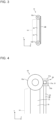
- Fig. 4 illustrates a modification of the fixing part of the heat exchanger 10 according to Embodiment 1, where the support 20 is fixed to one of the headers 12.
- the fixing part, 30, according to the modification is formed by the first frame segment 21a of the support 20, and locking parts 31a and 31b.
- the locking parts 31a and 31b are provided on the first header 12a.
- the fixing part 30 is provided at each of the four corners of the rectangular support 20, and the support 20 is fixed to the headers 12 at the fixing parts 30.
- the first frame segment 21a of the support 20 is fitted between the locking parts 31a and 31b.
- the first frame segment 21a is prevented from moving in the Y-direction and the Z-direction by the locking parts 31a and 31b.
- Such fixing parts 30 are located in the vicinities of the respective opposite ends of the first frame segment 21a in the X-direction.
- the third frame segments 21c connected to the respective opposite ends of the first frame segment 21a are stopped by the respective locking parts 31b. Thus, displacement of the support 20 in the X-direction is prevented.
- the fixing part 30 is only exemplary and may be combined with any other fastening part, such as a bolt, for fixing the support 20 to the header 12.
- Fig. 5 is a perspective view of a heat exchanger 10a, which is a modification of the heat exchanger 10 according to Embodiment 1.
- Fig. 6 is a side view of the heat exchanger 10a, which is a modification of the heat exchanger 10 according to Embodiment 2.
- the heat exchanger 10a which is a modification, includes the support 20 at each of the opposite faces of the plurality of heat transfer parts 11 in the Z-direction. That is, the opposite faces of the heat exchanger 10a in the Z-direction, which are the front face and the rear face, are formed by respective supports 20.
- the two supports 20 are fixed to the respective faces of each of the first header 12a and the second header 12b in the Z-direction.
- the two headers 12 are connected to each other by the two supports 20.
- Such a configuration provides higher strength than the strength of the heat exchanger 10 according to Embodiment 1.
- the supports 20 cover the respective opposite faces of the plurality of heat transfer parts 11 in the Z-direction. Therefore, the supports 20 not only prevent the entry of foreign matter from both respective faces in the Z-direction but also protect the plurality of heat transfer parts 11 in situations such as during the transport of the heat exchanger 210.
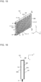
- Fig. 7 is a perspective view of a heat exchanger 10b, which is a modification of the heat exchanger 10 according to Embodiment 1.
- Fig. 8 is a front view of a support 20b, which is included in the heat exchanger 10b illustrated in Fig. 7 .
- the support 20b included in the heat exchanger 10b which is a modification, includes partitions 27a and 27b, which extend diagonally to the X-direction and the Y-direction. As illustrated in Fig. 8 , the partitions 27a and the partitions 27b are orthogonal to each other. Openings 25 are each defined by the inclined partitions 27a and 27b or by the partitions 27a and 27b and the frame 21.
- the support 20b including the inclined partitions 27a and 27b exhibits great ease of drainage of any dew water that may be generated on the support 20b.
- any waterdrops adhering to the partitions 27a and 27b flow downward under the influence of gravity.
- dew water does not keep staying on the partitions 27a and 27b. Accordingly, retention of dew water and frosting with frozen dew water are prevented. Consequently, the reduction in the ease of air passage through the heat exchanger 10b is prevented.
- the support 20b is a combination of the frame 21, which extends in the X-direction and the Y-direction, and the partitions 27a and 27b, which are inclined. Therefore, the support 20b exhibits high strength to deformation in the XY-plane. Accordingly, the heat exchanger 10b including the support 20b exhibits increased strength to a deformation that may tilt the plurality of heat transfer parts 11 in the X-direction. Furthermore, a load that may act in such a direction as to buckle the plurality of heat transfer parts 11 is borne not only by the third frame segments 21c but also by the partitions 27a and 27b, which extend diagonally to the Y-direction. Accordingly, the heat exchanger 10b also exhibits increased strength to a load acting in the Y-direction.
- a heat exchanger 210 according to Embodiment 2 will be described below.
- the heat exchanger 210 is obtained by changing the shape of the support 20 or 20b according to Embodiment 1. Elements having the same functions and effects as those described in Embodiment 1 are denoted by corresponding ones of the reference signs used in Embodiment 1, and description of such elements is omitted.
- Fig. 9 is a perspective view of the heat exchanger 210 according to Embodiment 2.
- Fig. 10 is a top view of the heat exchanger 210 according to Embodiment 2.
- the heat exchanger 210 according to Embodiment 2 includes a support 220, which is located at the plurality of heat transfer parts 11 in the Z-direction.
- the support 220 is different from the support 20 or 20b according to Embodiment 1 in the shape at its opposite ends in the X-direction.
- the support 220 is folded and extends in the backward Z-direction at its opposite ends in the X-direction.
- the support 220 includes first folded portions 24, which are located at the respective opposite ends of the support 220 in the X-direction and each extend in the backward Z-direction.
- the support 220 according to Embodiment 2 includes the partitions 27a and 27b, which extend diagonally to the X-direction and the Y-direction.
- the partitions 27a and 27b are located at the face of the support 220 that is oriented toward the Z-direction and are extended into the first folded portions 24.
- the partitions 27a and 27b may be absent in the first folded portions 24.
- the first folded portions 24 of the support 220 hold the headers 12 between the first folded portions 24 in the X-direction.
- the support 220 has a rectangular U-shape in top view and therefore exhibits high strength to deformation in the XZ-plane. Furthermore, the support 220 is joined to the headers 12. Accordingly, deformation of the heat exchanger 210 in the XZ-plane is prevented.
- the first frame segment 21a and the second frame segment 21b at the Y-direction opposite ends of the support 220 are each folded at corresponding ones of the X-direction opposite ends and extend in the backward Z-direction, thereby forming the respective first folded portions 24.
- the support 220 further includes fourth frame segments 21d, each of which forms the end of a corresponding one of the first folded portions 24 in the backward Z-direction.
- the third frame segments 21c are located at the respective ends of the first folded portions 24 in the Z-direction.
- the third frame segments 21c may be omitted. However, providing the third frame segments 21c enhances the effect of strengthening the heat exchanger 210.
- the support 220 exhibits high rigidity by employing the first folded portions 24 that are located at the respective the X-direction ends and extend in the Z-direction. Consequently, the effect of strengthening the heat exchanger 210 is enhanced.
- the first folded portions 24 are located at the respective X-direction ends and therefore do not hinder the passage of air through the heat exchanger 210.
- the partitions 27a and 27b of the support 220 are inclined as with the case of the support 20b according to Embodiment 1. Such a configuration exhibits great ease of drainage and increased strength.
- the partitions 27a and the partitions 27b of the support 220 do not necessarily need to be inclined and may extend in the X-direction and the Y-direction, respectively, as with the case of the first partitions 22a and the second partitions 22b according to Embodiment 1.
- a heat exchanger 310 according to Embodiment 3 will be described below.
- the heat exchanger 310 is obtained by changing the shape of the support 20 or 20b according to Embodiment 1.
- Elements having the same functions and effects as those described in Embodiment 1 are denoted by corresponding ones of the reference signs used in Embodiment 1, and description of such elements is omitted.
- Fig. 11 is a perspective view of the heat exchanger 310 according to Embodiment 3.
- Fig. 12 is a top view of the heat exchanger 310 according to Embodiment 3.
- the heat exchanger 310 includes a support 320. As illustrated in Fig. 12 , the support 320 is folded and extends in the Z-direction at a portion in the X-direction. As with the case of the heat exchanger 10a according to Embodiment 1, the support 320 covers the opposite faces of the heat exchanger 310 in the Z-direction.
- the support 320 has faces 320a and 320b, which are located at respective opposite sides of the plurality of heat transfer parts 11 and are connected to each other by a first folded portion 324.
- the faces 320a and 320b connected to each other by the first folded portion 324 hold the heat exchanger 310 between the faces 320a and 320b from both sides in the Z-direction.
- the face 320a is also referred to as the first portion
- the face 320b is also referred to as the second portion.
- the support 320 is a single continuous unit. That is, the support 320 includes a small number of components. Accordingly, the cost of the heat exchanger 310 is reduced, and the ease of manufacturing of the heat exchanger 310 is increased.
- the support 320 according to Embodiment 3 includes the partitions 27a that are inclined in one direction but includes no partitions 27b that intersect the partitions 27a.
- the partitions 27a extend continuously over the support 320 from the face 320a to the face 320b. Therefore, when the heat exchanger 310 is seen in the Z-direction, portions of the partitions 27a forming the face 320a and portions of the partitions 27a forming the face 320b appear to intersect each other.
- the partitions 27a are inclined in one direction over the entirety of the support 320.
- the support 320 When the support 320 is assembled into the heat exchanger 310, the direction in which the partitions 27a are inclined is symmetrical between that in the front face of the heat exchanger 310 and that in the rear face of the heat exchanger 310. Accordingly, the support 320 uniformly resists a force that may act on the heat exchanger 310 in such a manner as to tilt the plurality of heat transfer parts 11 in the X-direction and a force that may act on the heat exchanger 310 in such a manner as to tilt the plurality of heat transfer parts 11 in the backward X-direction.
- a heat exchanger 410 according to Embodiment 4 will be described below.
- the heat exchanger 410 is obtained by changing the shape of the support 20 or 20b according to Embodiment 1.
- Elements having the same functions and effects as those described in Embodiment 1 are denoted by corresponding ones of the reference signs used in Embodiment 1, and description of such elements is omitted.
- Fig. 13 is a perspective view of the heat exchanger 410 according to Embodiment 4.
- Fig. 14 is a side view of the heat exchanger 410 according to Embodiment 4.
- the heat exchanger 410 according to Embodiment 4 includes a support 420. As illustrated in Fig. 14 , the support 420 is folded and extends in the Z-direction at a portion in the Y-direction. In the heat exchanger 410, as with the case of the heat exchanger 10a according to Embodiment 1, the support 420 covers the opposite faces of the plurality of heat transfer parts 11 in the Z-direction.
- the support 420 has faces 420a and 420b, which are located at the plurality of heat transfer parts 11 in the Z-direction and are connected to each other by a second folded portion 28.
- the support 420 holds the heat exchanger 410 from the Z-direction opposite sides, specifically, the face 420a and the face 420b connected to each other by the second folded portion 28 hold the heat exchanger 410 between the face 420a and the face 420b from both sides in the Z-direction.
- the second folded portion 28 extends in the Z-direction along the upper surface of the first header 12a.
- the support 420 according to Embodiment 4 includes the partitions 27a that are inclined in one direction but includes no partitions 27b that intersect the partitions 27a.
- the partitions 27a extend continuously over the support 420 from the face 420a to the face 420b. Therefore, when the heat exchanger 410 is seen in the Z-direction, portions of the partitions 27a forming the face 420a and portions of the partitions 27a forming the face 420b appear to intersect each other.
- the partitions 27a are inclined in one direction over the entirety of the support 420.
- the support 420 When the support 420 is assembled into the heat exchanger 410, the direction in which the partitions 27a are inclined is symmetrical between that in the front face of the heat exchanger 410 and that in the rear face of the heat exchanger 410. Accordingly, the support 420 uniformly resists a force that may act on the heat exchanger 410 in such a manner as to tilt the plurality of heat transfer parts 11 in the X-direction and a force that may act on the heat exchanger 410 in such a manner as to tilt the plurality of heat transfer parts 11 in the backward X-direction.
- a heat exchanger 510 according to Embodiment 5 will be described below.
- the heat exchanger 510 is obtained by changing the shape of the support 20 or 20b according to Embodiment 1. Elements having the same functions and effects as those described in Embodiment 1 are denoted by corresponding ones of the reference signs used in Embodiment 1, and description of such elements is omitted.
- Fig. 15 is a perspective view of the heat exchanger 510 according to Embodiment 5.
- Fig. 16 is a top view of the heat exchanger 510 according to Embodiment 5.
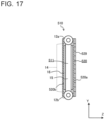
- Fig. 17 is a side view of the heat exchanger 510 according to Embodiment 5.
- the heat exchanger 510 according to Embodiment 5 includes a support 520. As with the case of the support 320 of the heat exchanger 310 according to Embodiment 3, the support 520 included in the heat exchanger 510 according to Embodiment 5 covers the front face and the rear face of the heat exchanger 510.
- the support 520 includes partitions 527a, which are inclined in one direction. The partitions 527a extend uniformly over the entirety of the support 520. When the heat exchanger 510 is seen in the Z-direction, portions of the partitions 527a on the front face of the heat exchanger 510 and portions of the partitions 527a on the rear face of the heat exchanger 510 intersect each other.
- Portions of the partitions 527a on a face 520a of the support 520 are provided with projection parts 529.
- the projection parts 529 are plate-like parts extending along and joined to the respective portions of the partitions 527a that form the face 520a.
- the projection parts 529 are preferably provided on the face 520a, which receives incoming air. In Embodiment 5, air flows in the backward Z-direction.
- the projection parts 529 also serve as heat transfer surfaces. In such a case, the projection parts 529 compensate for the insufficiency in the heat transfer area of the heat exchanger 510, which is referred to as a finless heat exchanger.
- the heat exchanger 510 includes a plurality of heat transfer parts 511.
- the plurality of heat transfer parts 511 each include heat transfer plates 16, which are each shaped in a plate form and extend from the respective Z-direction ends of the heat transfer part 511.
- the support 520 may be in contact with or joined to the Z-direction ends of the heat transfer plates 16. In such a configuration, the support 520 and the heat transfer plates 16 are thermally connected to each other. Therefore, the support 520 serves as a heat transfer surface of the heat exchanger 510 while enhancing the strength of the heat exchanger 510.
- the support 520 includes the partitions 527a, which extend diagonally to the X-direction and the Y-direction, dew water thus does not stay on the projection parts 529. Therefore, the ease of air passage through the heat exchanger 510 is secured. Furthermore, for example, when the heat exchanger 510 is installed in a refrigeration cycle apparatus 100, the projection parts 529 of the support 520 are positioned in the vicinity of the outside of the refrigeration cycle apparatus 100. Therefore, the projection parts 529 start to corrode earlier than the heat transfer parts 11 and the headers 12. In particular, when the support 520 is made of a metal material that is more likely to be ionized than the materials of which the heat transfer parts 11 and the headers 12 are made, the support 520 is given priority to corrode.
- the corrosion of the heat transfer parts 11 is prevented. Consequently, refrigerant leakage due to corrosion is prevented. Furthermore, a cost reduction is possible by reducing the thicknesses of the materials of which the heat transfer parts 11 and the headers 12 are made.
- the present disclosure is not limited to the above configurations.
- the heat exchangers 10, 10a, 10b, 210, 310, 410, and 510 according to Embodiments 1 to 5 may each employ any combination of the above features.
- the configuration of the support 20 of the heat exchanger 10b that includes the partitions 27a and 27b may be applied to the heat exchanger 310 or any of the other heat exchangers.
Landscapes
- Engineering & Computer Science (AREA)
- Physics & Mathematics (AREA)
- Thermal Sciences (AREA)
- Mechanical Engineering (AREA)
- General Engineering & Computer Science (AREA)
- Heat-Exchange Devices With Radiators And Conduit Assemblies (AREA)
Abstract
Description
- The present disclosure relates to a heat exchanger and a refrigeration cycle apparatus including the heat exchanger, particularly to a configuration in which the buckling of heat transfer parts is prevented.
- In recent years, to provide refrigeration cycle apparatuses with higher performance and lighter weight, the introduction of aluminum flat tubes as heat transfer tubes intended for heat exchangers of refrigeration and air-conditioning apparatuses has been facilitated in place of some copper round tubes. Furthermore, in recent years, the importance of reducing the use of refrigerants having high global warming potentials has required the development of high-performance heat exchangers employing flat tubes having a much smaller inside capacity than the inside capacity of aluminum flat tubes employed in known heat exchangers.
- In a proposed heat exchanger, for example, for the purpose of making the inside capacity of flat tubes much smaller than the inside capacity of aluminum flat tubes of other known heat exchangers, the minor-axis length of a plurality of flat tubes arranged parallel to each other in the axial direction of header pipes is set to, for example, smaller than 1 mm (see Patent Literature 1, for example). Herein, the minor-axis length refers to the length of the shortest diameter in a right-angled cross section of the flat tube. The heat exchanger disclosed by Patent Literature 1 includes assisting parts each provided between adjacent ones of the flat tubes. The assisting parts each extend in the direction of arrangement of refrigerant passages, thereby retaining the interval between adjacent ones of the flat tubes.
- Patent Literature 1:
Japanese Unexamined Patent Application Publication No. 2018-162953 - In the heat exchanger disclosed by Patent Literature 1, however, it is difficult for only a single support to prevent the buckling of the flat tubes in the tube-axis direction. Accordingly, the heat exchanger includes a plurality of supports and is thus capable of preventing the buckling of the flat tubes in the tube-axis direction. Nevertheless, such a heat exchanger that includes a plurality of supports has a problem in that the ease of drainage of condensed water and the ease of air passage tend to be reduced.
- The present disclosure is to solve the above problem and to provide a heat exchanger and a refrigeration cycle apparatus in each of which the buckling of flat tubes in the tube-axis direction is prevented while the ease of drainage and the ease of air passage are maintained.
- A heat exchanger according to an embodiment of the present disclosure includes a plurality of heat transfer parts arranged in a first direction and spaced apart from each other, the plurality of heat transfer parts extending in a second direction and allowing refrigerant to flow through inside the plurality of heat transfer parts; a first header extending in the first direction and connected to one end of each of the plurality of heat transfer parts; a second header extending in the first direction and connected to an other end of each of the plurality of heat transfer parts; and a support extending along the first direction and the second direction and having an opening, the support being located at at least one face of the plurality of heat transfer parts in a third direction that is perpendicular to the first direction and the second direction, the support being fixed to the first header and the second header.
- A refrigeration cycle apparatus according to another embodiment of the present disclosure includes the heat exchanger according to an embodiment of the present disclosure.
- According to an embodiment of the present disclosure, the heat exchanger includes the support located along the first direction, in which the plurality of heat transfer parts are arranged in parallel to each other, and along the second direction, in which the plurality of heat transfer parts extend, and the support is fixed to the first header and the second header. Thus, the support retains the interval between the first header and the second header in the tube-axis direction of the plurality of heat transfer parts, that is, in the second direction. Such a configuration prevents deformation due to buckling of the plurality of heat transfer parts in the axial direction.
-
- [
Fig. 1] Fig. 1 is a refrigerant circuit diagram of arefrigeration cycle apparatus 100, including aheat exchanger 10, according to Embodiment 1. - [
Fig. 2] Fig. 2 is a perspective view of theheat exchanger 10 according to Embodiment 1. - [
Fig. 3] Fig. 3 is a side view of theheat exchanger 10 according to Embodiment 1. - [
Fig. 4] Fig. 4 illustrates a modification of a fixing part of theheat exchanger 10 according to Embodiment 1, where asupport 20 is fixed to aheader 12. - [
Fig. 5] Fig. 5 is a perspective view of aheat exchanger 10a, which is a modification of theheat exchanger 10 according to Embodiment 1. - [
Fig. 6] Fig. 6 is a side view of theheat exchanger 10a, which is a modification of theheat exchanger 10 according toEmbodiment 2. - [
Fig. 7] Fig. 7 is a perspective view of aheat exchanger 10b, which is a modification of theheat exchanger 10 according to Embodiment 1. - [
Fig. 8] Fig. 8 is a front view of asupport 20b, which is included in theheat exchanger 10b illustrated inFig. 7 . - [
Fig. 9] Fig. 9 is a perspective view of aheat exchanger 210 according toEmbodiment 2. - [
Fig. 10] Fig. 10 is a top view of theheat exchanger 210 according to Embodiment 2. - [
Fig. 11] Fig. 11 is a perspective view of aheat exchanger 310 according to Embodiment 3. - [
Fig. 12] Fig. 12 is a top view of theheat exchanger 310 according to Embodiment 3. - [
Fig. 13] Fig. 13 is a perspective view of aheat exchanger 410 according to Embodiment 4. - [
Fig. 14] Fig. 14 is a side view of theheat exchanger 410 according to Embodiment 4. - [
Fig. 15] Fig. 15 is a perspective view of aheat exchanger 510 according to Embodiment 5. - [
Fig. 16] Fig. 16 is a top view of theheat exchanger 510 according to Embodiment 5. - [
Fig. 17] Fig. 17 is a side view of theheat exchanger 510 according to Embodiment 5. - A heat exchanger and a refrigeration cycle apparatus according to Embodiment 1 will be described below with reference to the drawings and relevant materials. In the drawings, including
Fig. 1 , to be referred to below, factors such as relative sizes and shapes of individual elements may be different from those of actual elements. In the drawings to be referred to below, the same reference signs denote the same or equivalent elements and are consistent throughout this specification. For easy understanding, terms indicating directions (such as "upper", "lower", "right", "left", "front", and "rear") will be used according to need. Such terms, however, are only for convenience of description and do not limit the arrangements or orientations of the apparatus and individual elements. Herein, the positional relationship between relevant elements, the directions in which relevant elements extend, and the direction in which relevant elements are arranged are those in a state where the heat exchanger is installed for use. -
Fig. 1 is a refrigerant circuit diagram of arefrigeration cycle apparatus 100, including aheat exchanger 10, according to Embodiment 1. InFig. 1 , dotted-line arrows represent the direction in which refrigerant in arefrigerant circuit 110 flows in a cooling operation, and solid-line arrows represent the direction in which the refrigerant flows in a heating operation. First, with reference toFig. 1 , therefrigeration cycle apparatus 100 including theheat exchanger 10 will be described. Embodiment 1 relates to a case where therefrigeration cycle apparatus 100 serves as an air-conditioning apparatus. Therefrigeration cycle apparatus 100 is also applicable to apparatuses intended for refrigeration uses or air-conditioning uses such as a refrigerator, a freezer, a vending machine, an air-conditioning apparatus, a freezing apparatus, and a water heater. Therefrigerant circuit 110 illustrated inFig. 1 is only exemplary. The configuration and other relevant factors of circuit elements are not limited to those to be described in the following embodiments and may be changed according to need within the technical scope of the embodiments. - The
refrigeration cycle apparatus 100 includes acompressor 101, apassage switcher 102, anindoor heat exchanger 103, adecompressor 104, and anoutdoor heat exchanger 105, which are all connected to each other by refrigerant pipes to form a loop serving as therefrigerant circuit 110. At least one of theoutdoor heat exchanger 105 and theindoor heat exchanger 103 includes theheat exchanger 10 to be described below. Therefrigeration cycle apparatus 100 includes anoutdoor unit 106 and anindoor unit 107. Theoutdoor unit 106 includes thecompressor 101, thepassage switcher 102, theoutdoor heat exchanger 105, thedecompressor 104, and anoutdoor fan 108. Theoutdoor fan 108 supplies outdoor air to theoutdoor heat exchanger 105. Theindoor unit 107 includes theindoor heat exchanger 103 and anindoor fan 109. Theindoor fan 109 supplies air to theindoor heat exchanger 103. Theoutdoor unit 106 and theindoor unit 107 are connected to each other by anextension pipe 111 and anextension pipe 112, which are two of the refrigerant pipes. - The
compressor 101 is a fluid machine that compresses refrigerant sucked into thecompressor 101 and discharges the compressed refrigerant. Thepassage switcher 102 is, for example, a four-way valve and is configured to establish a refrigerant passage that is switched between one for the cooling operation and one for the heating operation under the control of a controller (not illustrated). - The
indoor heat exchanger 103 causes the refrigerant flowing inside theindoor heat exchanger 103 and the indoor air supplied by theindoor fan 109 to exchange their heat. Theindoor heat exchanger 103 serves as a condenser in the heating operation and as an evaporator in the cooling operation. - The
decompressor 104 is, for example, an expansion valve and decompresses the refrigerant. Thedecompressor 104 may be an electronic expansion valve whose opening degree is regulated under the control of the controller. - The
outdoor heat exchanger 105 causes the refrigerant flowing inside theoutdoor heat exchanger 105 and the air supplied by theoutdoor fan 108 to exchange their heat. Theoutdoor heat exchanger 105 serves as an evaporator in the heating operation and as a condenser in the cooling operation. - An exemplary operation of the
refrigeration cycle apparatus 100 will be described below with reference toFig. 1 . In the heating operation of therefrigeration cycle apparatus 100, the refrigerant is discharged from thecompressor 101 in the form of gas having a high pressure and a high temperature and flows through thepassage switcher 102 into theindoor heat exchanger 103, where the refrigerant exchanges heat with the air supplied by theindoor fan 109 and thus condenses. The refrigerant having condensed takes the form of liquid having a high pressure and is discharged from theindoor heat exchanger 103 into thedecompressor 104, where the refrigerant turns into two-phase gas-liquid refrigerant having a low pressure. The two-phase gas-liquid refrigerant having a low pressure flows into theoutdoor heat exchanger 105, where the refrigerant exchanges heat with the air supplied by theoutdoor fan 108 and thus evaporates. The refrigerant having evaporated takes the form of gas having a low pressure and is sucked into thecompressor 101. - In the cooling operation of the
refrigeration cycle apparatus 100, the refrigerant flows through therefrigerant circuit 110 in a direction opposite to the direction in the heating operation. Specifically, in the cooling operation of therefrigeration cycle apparatus 100, the refrigerant is discharged from thecompressor 101 in the form of gas having a high pressure and a high temperature and flows through thepassage switcher 102 into theoutdoor heat exchanger 105, where the refrigerant exchanges heat with the air supplied by theoutdoor fan 108 and thus condenses. The refrigerant having condensed takes the form of liquid having a high pressure and is discharged from theoutdoor heat exchanger 105 into thedecompressor 104, where the refrigerant turns into two-phase gas-liquid refrigerant having a low pressure. The two-phase gas-liquid refrigerant having a low pressure flows into theindoor heat exchanger 103, where the refrigerant exchanges heat with the air supplied by theindoor fan 109 and thus evaporates. The refrigerant having evaporated takes the form of gas having a low pressure and is sucked into thecompressor 101. -
Fig. 2 is a perspective view of theheat exchanger 10 according to Embodiment 1.Fig. 3 is a side view of theheat exchanger 10 according to Embodiment 1. With reference toFigs. 2 and3 , theheat exchanger 10 according to Embodiment 1 will be described below. - As illustrated in
Fig. 2 , theheat exchanger 10 includes a plurality ofheat transfer parts 11, afirst header 12a, asecond header 12b, and asupport 20. Thefirst header 12a and thesecond header 12b are connected to respective end portions of each of the plurality ofheat transfer parts 11. Thesupport 20 is fixed to thefirst header 12a and thesecond header 12b. The plurality ofheat transfer parts 11 are arranged side by side in the X-direction. The plurality ofheat transfer parts 11 are each oriented such that its tube axis extends in the Y-direction. In Embodiment 1, the Y-direction is parallel to the direction of gravity. The orientation of theheat exchanger 10 is not limited to the above. Theheat exchanger 10 may be oriented with the Y-direction that is made to extend diagonally to the direction of gravity. The plurality ofheat transfer parts 11 are regularly spaced apart from each other at an interval w1 in the X-direction. - The
first header 12a is connected to one end portion, in a tube-axis direction, of each of the plurality ofheat transfer parts 11. Thesecond header 12b is connected to the other end portion, in the tube-axis direction, of each of the plurality ofheat transfer parts 11. Thefirst header 12a and thesecond header 12b are each oriented with their longitudinal direction coinciding with the direction in which the plurality ofheat transfer parts 11 are arranged in parallel to each other. The longitudinal direction of thefirst header 12a and the longitudinal direction of thesecond header 12b are parallel to each other. Hereinafter, thefirst header 12a and thesecond header 12b are also collectively denoted as theheaders 12. - The plurality of
heat transfer parts 11 each have the opposite end portions fitted in therespective headers 12 and joined to theheaders 12 by joining means such as brazing. The plurality ofheat transfer parts 11 are arranged in parallel to each other in the X-direction. The plurality ofheat transfer parts 11 each include aheat transfer portion 14, which is a portion excluding the opposite end portions and is located between the lower surface of thefirst header 12a and the upper surface of thesecond header 12b. - The
support 20 extends parallel to the X-direction and the Y-direction and is located at the plurality ofheat transfer parts 11 in the Z-direction. Air flows through theheat exchanger 10 in the Z-direction. The plurality ofheat transfer parts 11 and thesupport 20 are arranged in series in the direction in which air flows into theheat exchanger 10. In Embodiment 1, thesupport 20 covers one face of the plurality ofheat transfer parts 11 in the Z-direction. Herein, the X-direction in which the plurality ofheat transfer parts 11 are arranged in parallel to each other is also referred to as the first direction, the Y-direction coinciding with the tube-axis direction of the plurality ofheat transfer parts 11 is also referred to as the second direction, and the Z-direction perpendicular to the X-direction and the Y-direction is also referred to as the third direction. - The plurality of
heat transfer parts 11 each allow the refrigerant to flow through inside theheat transfer part 11. The plurality ofheat transfer parts 11 each extend between thefirst header 12a and thesecond header 12b. The plurality ofheat transfer parts 11 are spaced apart from each other at an interval w1 in the X-direction and are arranged in parallel to each other in the direction in which theheaders 12 extend. The plurality ofheat transfer parts 11 each have an oblong or elliptical sectional shape or a rectangular sectional shape, and the major axis of the section extends in the Z-direction. The plurality ofheat transfer parts 11 each have lateral faces 15, each of which extends along the major axis of the section and faces a corresponding one of the lateral faces 15 of an adjacentheat transfer part 11. Between the lateral faces 15 of each adjacent two of the plurality ofheat transfer parts 11 that are located face to face is provided a gap serving as a passage for air. While theheat exchanger 10 according to Embodiment 1 employs a plurality of flat tubes serving as the plurality ofheat transfer parts 11, the plurality ofheat transfer parts 11 are not limited to flat tubes. For example, theheat transfer parts 11 may each be a plurality of thin circular tubes that are connected to each other in the Z-direction by a plate-like part. - In the
heat exchanger 10, the X-direction in which the plurality ofheat transfer parts 11 are arranged coincides with the horizontal direction. Note that the direction in which the plurality ofheat transfer parts 11 are arranged is not limited to the horizontal direction and may be the vertical direction or a direction extending diagonally to the vertical direction. Furthermore, in theheat exchanger 10, the direction in which each of the plurality ofheat transfer parts 11 extends coincides with the vertical direction. Note that the direction in which each of the plurality ofheat transfer parts 11 extends is not limited to the vertical direction and may be the horizontal direction or a direction extending diagonally to the vertical direction. - The lateral faces 15 of each adjacent two of the plurality of
heat transfer parts 11 that are located face to face are not connected to each other by any heat transfer promoter. The heat transfer promoter is, for example, a plate fin or a corrugated fin. That is, the plurality ofheat transfer parts 11 are connected to each other only by theheaders 12. - The
first header 12a and thesecond header 12b each extend in the X-direction and allow the refrigerant to flow through inside thefirst header 12a and thesecond header 12b. As illustrated inFig. 2 , for example, arefrigerant passage tube 42 is connected to one end of thesecond header 12b and allows the refrigerant to flow into thesecond header 12b. Then, the refrigerant is distributed to the plurality ofheat transfer parts 11. The distributed portions of refrigerant flow through the plurality of respectiveheat transfer parts 11 and merge together in thefirst header 12a. The refrigerant having merged is discharged from thefirst header 12a into arefrigerant passage tube 41, which is connected to one end of thefirst header 12a. - While the
headers 12 illustrated inFigs. 2 and3 each have a round columnar outline shape, the outline shape of theheaders 12 is not limited. The outline shape of theheaders 12 may be, for example, a cuboid or an elliptical column. The sectional shape of theheaders 12 may also be changed according to need. Moreover, the structure of each of theheaders 12 may be, for example, a cylinder with its opposite ends closed, or a stack of plate-like parts having slits. Thefirst header 12a and thesecond header 12b each have a refrigerant port through which the refrigerant is allowed to flow into and out of theheader - As illustrated in
Fig. 3 , thesupport 20 of theheat exchanger 10 covers one face of the plurality ofheat transfer parts 11 in the Z-direction. That is, thesupport 20 is oriented such that a face of thesupport 20 extending along the X-direction and the Y-direction is oriented toward the plurality ofheat transfer parts 11. As illustrated inFig. 2 , thesupport 20 hasopenings 25, which allow fluid to pass through thesupport 20 in a direction perpendicular to the face extending along the X-direction and the Y-direction, that is, in the Z-direction. - The
support 20 has a rectangular shape when seen in the Z-direction and includes aframe 21 andpartitions 22. Theframe 21 forms the outer periphery of thesupport 20. Thepartitions 22 divide the area enclosed by theframe 21 into a plurality of subareas. Theframe 21 of thesupport 20 includes afirst frame segment 21a, which extends along thefirst header 12a, asecond frame segment 21b, which extends along thesecond header 12b, and twothird frame segments 21c, which connect the ends of thefirst frame segment 21a and the ends of thesecond frame segment 21b to each other. Thefirst frame segment 21a, thesecond frame segment 21b, and the twothird frame segments 21c are assembled to form a rectangle. Thefirst frame segment 21a and thesecond frame segment 21b form opposite sides of therectangular frame 21. The twothird frame segments 21c form the other opposite sides of therectangular frame 21. - The
partitions 22 of thesupport 20 according to Embodiment 1 includesfirst partitions 22a, which each extend in the X-direction, and second partitions 22b, which each extend in the Y-direction. Thepartitions 22 are arranged such that thepartitions 22 divide the area enclosed by theframe 21 into a plurality of subareas. In Embodiment 1, thefirst partitions 22a and the second partitions 22b are orthogonal to each other, thereby forming meshes. That is, thesupport 20 is meshes having theopenings 25. Theopenings 25 are each defined by thepartitions 22 or by thepartitions 22 and theframe 21. - The
support 20 formed as a combination of theframe 21 and thepartitions 22 resists deformation that may occur in the XY-plane. Thesupport 20 is fixed to at least thefirst header 12a and thesecond header 12b. Therefore, the relative displacement between thefirst header 12a and thesecond header 12b is prevented. Consequently, the deformation of theheat exchanger 10 as a whole is prevented. Specifically, the deformation due to buckling of the plurality ofheat transfer parts 11 in the Y-direction and the tilting of the plurality ofheat transfer parts 11 in the X-direction are prevented. Thus, theheat exchanger 10 exhibits increased strength with the minimum addition, which is thesupport 20. - The size of the
openings 25 may be determined according to need. In Embodiment 1, when the interval between thepartitions 22 of thesupport 20 is set according to need, the entry of foreign matter into theheat exchanger 10 can be prevented. Furthermore, thesupport 20 protects theheat transfer parts 11 during the transport of theheat exchanger 10 or therefrigeration cycle apparatus 100 including theheat exchanger 10. - The
support 20 is preferably made of a material having higher strength than the strength of the material of which the plurality ofheat transfer parts 11 are made. In Embodiment 1, the flat tubes serving as theheat transfer parts 11 are made of, for example, aluminum. Therefore, thesupport 20 is preferably made of a material, such as stainless steel, having higher rigidity and strength than the rigidity and strength of aluminum. - The
heat exchanger 10 includes fixing parts where thesupport 20 is fixed to theheaders 12. In theheat exchanger 10 illustrated inFigs. 2 and3 , thesupport 20 and theheaders 12 are joined to each other by, for example, welding. Alternatively, any fastening parts such as bolts may be employed at the fixing parts for fastening, fitting, or locking. -
Fig. 4 illustrates a modification of the fixing part of theheat exchanger 10 according to Embodiment 1, where thesupport 20 is fixed to one of theheaders 12. The fixing part, 30, according to the modification is formed by thefirst frame segment 21a of thesupport 20, and lockingparts parts first header 12a. The fixingpart 30 is provided at each of the four corners of therectangular support 20, and thesupport 20 is fixed to theheaders 12 at the fixingparts 30. In the fixingpart 30 illustrated inFig. 4 , thefirst frame segment 21a of thesupport 20 is fitted between the lockingparts first frame segment 21a is prevented from moving in the Y-direction and the Z-direction by the lockingparts parts 30 are located in the vicinities of the respective opposite ends of thefirst frame segment 21a in the X-direction. Thethird frame segments 21c connected to the respective opposite ends of thefirst frame segment 21a are stopped by therespective locking parts 31b. Thus, displacement of thesupport 20 in the X-direction is prevented. - The fixing
part 30 is only exemplary and may be combined with any other fastening part, such as a bolt, for fixing thesupport 20 to theheader 12. -
Fig. 5 is a perspective view of aheat exchanger 10a, which is a modification of theheat exchanger 10 according to Embodiment 1.Fig. 6 is a side view of theheat exchanger 10a, which is a modification of theheat exchanger 10 according toEmbodiment 2. As illustrated inFigs. 5 and 6 , theheat exchanger 10a, which is a modification, includes thesupport 20 at each of the opposite faces of the plurality ofheat transfer parts 11 in the Z-direction. That is, the opposite faces of theheat exchanger 10a in the Z-direction, which are the front face and the rear face, are formed byrespective supports 20. - The two
supports 20 are fixed to the respective faces of each of thefirst header 12a and thesecond header 12b in the Z-direction. The twoheaders 12 are connected to each other by the two supports 20. Such a configuration provides higher strength than the strength of theheat exchanger 10 according to Embodiment 1. - The supports 20 cover the respective opposite faces of the plurality of
heat transfer parts 11 in the Z-direction. Therefore, thesupports 20 not only prevent the entry of foreign matter from both respective faces in the Z-direction but also protect the plurality ofheat transfer parts 11 in situations such as during the transport of theheat exchanger 210. -
Fig. 7 is a perspective view of aheat exchanger 10b, which is a modification of theheat exchanger 10 according to Embodiment 1.Fig. 8 is a front view of asupport 20b, which is included in theheat exchanger 10b illustrated inFig. 7 . Thesupport 20b included in theheat exchanger 10b, which is a modification, includespartitions Fig. 8 , thepartitions 27a and thepartitions 27b are orthogonal to each other.Openings 25 are each defined by theinclined partitions partitions frame 21. - The
support 20b including theinclined partitions support 20b. Specifically, when theheat exchanger 10b is installed with the Y-direction coinciding with the direction of gravity, any waterdrops adhering to thepartitions heat exchanger 10b, dew water does not keep staying on thepartitions heat exchanger 10b is prevented. - The
support 20b is a combination of theframe 21, which extends in the X-direction and the Y-direction, and thepartitions support 20b exhibits high strength to deformation in the XY-plane. Accordingly, theheat exchanger 10b including thesupport 20b exhibits increased strength to a deformation that may tilt the plurality ofheat transfer parts 11 in the X-direction. Furthermore, a load that may act in such a direction as to buckle the plurality ofheat transfer parts 11 is borne not only by thethird frame segments 21c but also by thepartitions heat exchanger 10b also exhibits increased strength to a load acting in the Y-direction. - A
heat exchanger 210 according toEmbodiment 2 will be described below. Theheat exchanger 210 is obtained by changing the shape of thesupport -
Fig. 9 is a perspective view of theheat exchanger 210 according toEmbodiment 2.Fig. 10 is a top view of theheat exchanger 210 according toEmbodiment 2. Theheat exchanger 210 according toEmbodiment 2 includes asupport 220, which is located at the plurality ofheat transfer parts 11 in the Z-direction. Thesupport 220 is different from thesupport support 220 is folded and extends in the backward Z-direction at its opposite ends in the X-direction. Specifically, thesupport 220 includes first foldedportions 24, which are located at the respective opposite ends of thesupport 220 in the X-direction and each extend in the backward Z-direction. - As with the case of the
support 20b according to Embodiment 1, thesupport 220 according toEmbodiment 2 includes thepartitions partitions support 220 that is oriented toward the Z-direction and are extended into the first foldedportions 24. Alternatively, thepartitions portions 24. - When the
heat exchanger 210 is seen from above as illustrated inFig. 10 , the first foldedportions 24 of thesupport 220 hold theheaders 12 between the first foldedportions 24 in the X-direction. Thesupport 220 has a rectangular U-shape in top view and therefore exhibits high strength to deformation in the XZ-plane. Furthermore, thesupport 220 is joined to theheaders 12. Accordingly, deformation of theheat exchanger 210 in the XZ-plane is prevented. - The
first frame segment 21a and thesecond frame segment 21b at the Y-direction opposite ends of thesupport 220 are each folded at corresponding ones of the X-direction opposite ends and extend in the backward Z-direction, thereby forming the respective first foldedportions 24. Thesupport 220 further includes fourth frame segments 21d, each of which forms the end of a corresponding one of the first foldedportions 24 in the backward Z-direction. Thethird frame segments 21c are located at the respective ends of the first foldedportions 24 in the Z-direction. Thethird frame segments 21c may be omitted. However, providing thethird frame segments 21c enhances the effect of strengthening theheat exchanger 210. - The
support 220 exhibits high rigidity by employing the first foldedportions 24 that are located at the respective the X-direction ends and extend in the Z-direction. Consequently, the effect of strengthening theheat exchanger 210 is enhanced. The first foldedportions 24 are located at the respective X-direction ends and therefore do not hinder the passage of air through theheat exchanger 210. - According to
Embodiment 2, thepartitions support 220 are inclined as with the case of thesupport 20b according to Embodiment 1. Such a configuration exhibits great ease of drainage and increased strength. Thepartitions 27a and thepartitions 27b of thesupport 220 do not necessarily need to be inclined and may extend in the X-direction and the Y-direction, respectively, as with the case of thefirst partitions 22a and the second partitions 22b according to Embodiment 1. - A
heat exchanger 310 according to Embodiment 3 will be described below. Theheat exchanger 310 is obtained by changing the shape of thesupport -
Fig. 11 is a perspective view of theheat exchanger 310 according to Embodiment 3.Fig. 12 is a top view of theheat exchanger 310 according to Embodiment 3. Theheat exchanger 310 includes asupport 320. As illustrated inFig. 12 , thesupport 320 is folded and extends in the Z-direction at a portion in the X-direction. As with the case of theheat exchanger 10a according to Embodiment 1, thesupport 320 covers the opposite faces of theheat exchanger 310 in the Z-direction. Thesupport 320 hasfaces heat transfer parts 11 and are connected to each other by a first foldedportion 324. In other words, thefaces portion 324 hold theheat exchanger 310 between thefaces face 320a is also referred to as the first portion, and theface 320b is also referred to as the second portion. - The
support 320 is a single continuous unit. That is, thesupport 320 includes a small number of components. Accordingly, the cost of theheat exchanger 310 is reduced, and the ease of manufacturing of theheat exchanger 310 is increased. - The
support 320 according to Embodiment 3 includes thepartitions 27a that are inclined in one direction but includes nopartitions 27b that intersect thepartitions 27a. Thepartitions 27a extend continuously over thesupport 320 from theface 320a to theface 320b. Therefore, when theheat exchanger 310 is seen in the Z-direction, portions of thepartitions 27a forming theface 320a and portions of thepartitions 27a forming theface 320b appear to intersect each other. When thesupport 320 is unfolded, thepartitions 27a are inclined in one direction over the entirety of thesupport 320. When thesupport 320 is assembled into theheat exchanger 310, the direction in which thepartitions 27a are inclined is symmetrical between that in the front face of theheat exchanger 310 and that in the rear face of theheat exchanger 310. Accordingly, thesupport 320 uniformly resists a force that may act on theheat exchanger 310 in such a manner as to tilt the plurality ofheat transfer parts 11 in the X-direction and a force that may act on theheat exchanger 310 in such a manner as to tilt the plurality ofheat transfer parts 11 in the backward X-direction. - A
heat exchanger 410 according to Embodiment 4 will be described below. Theheat exchanger 410 is obtained by changing the shape of thesupport -
Fig. 13 is a perspective view of theheat exchanger 410 according to Embodiment 4.Fig. 14 is a side view of theheat exchanger 410 according to Embodiment 4. Theheat exchanger 410 according to Embodiment 4 includes asupport 420. As illustrated inFig. 14 , thesupport 420 is folded and extends in the Z-direction at a portion in the Y-direction. In theheat exchanger 410, as with the case of theheat exchanger 10a according to Embodiment 1, thesupport 420 covers the opposite faces of the plurality ofheat transfer parts 11 in the Z-direction. Thesupport 420 hasfaces heat transfer parts 11 in the Z-direction and are connected to each other by a second foldedportion 28. In other words, thesupport 420 holds theheat exchanger 410 from the Z-direction opposite sides, specifically, theface 420a and theface 420b connected to each other by the second foldedportion 28 hold theheat exchanger 410 between theface 420a and theface 420b from both sides in the Z-direction. The second foldedportion 28 extends in the Z-direction along the upper surface of thefirst header 12a. - The
support 420 according to Embodiment 4 includes thepartitions 27a that are inclined in one direction but includes nopartitions 27b that intersect thepartitions 27a. Thepartitions 27a extend continuously over thesupport 420 from theface 420a to theface 420b. Therefore, when theheat exchanger 410 is seen in the Z-direction, portions of thepartitions 27a forming theface 420a and portions of thepartitions 27a forming theface 420b appear to intersect each other. When thesupport 420 is unfolded, thepartitions 27a are inclined in one direction over the entirety of thesupport 420. When thesupport 420 is assembled into theheat exchanger 410, the direction in which thepartitions 27a are inclined is symmetrical between that in the front face of theheat exchanger 410 and that in the rear face of theheat exchanger 410. Accordingly, thesupport 420 uniformly resists a force that may act on theheat exchanger 410 in such a manner as to tilt the plurality ofheat transfer parts 11 in the X-direction and a force that may act on theheat exchanger 410 in such a manner as to tilt the plurality ofheat transfer parts 11 in the backward X-direction. - A
heat exchanger 510 according to Embodiment 5 will be described below. Theheat exchanger 510 is obtained by changing the shape of thesupport -
Fig. 15 is a perspective view of theheat exchanger 510 according to Embodiment 5.Fig. 16 is a top view of theheat exchanger 510 according to Embodiment 5.Fig. 17 is a side view of theheat exchanger 510 according to Embodiment 5. Theheat exchanger 510 according to Embodiment 5 includes asupport 520. As with the case of thesupport 320 of theheat exchanger 310 according to Embodiment 3, thesupport 520 included in theheat exchanger 510 according to Embodiment 5 covers the front face and the rear face of theheat exchanger 510. Thesupport 520 includespartitions 527a, which are inclined in one direction. Thepartitions 527a extend uniformly over the entirety of thesupport 520. When theheat exchanger 510 is seen in the Z-direction, portions of thepartitions 527a on the front face of theheat exchanger 510 and portions of thepartitions 527a on the rear face of theheat exchanger 510 intersect each other. - Portions of the
partitions 527a on aface 520a of thesupport 520 are provided withprojection parts 529. Theprojection parts 529 are plate-like parts extending along and joined to the respective portions of thepartitions 527a that form theface 520a. Theprojection parts 529 are preferably provided on theface 520a, which receives incoming air. In Embodiment 5, air flows in the backward Z-direction. Theprojection parts 529 also serve as heat transfer surfaces. In such a case, theprojection parts 529 compensate for the insufficiency in the heat transfer area of theheat exchanger 510, which is referred to as a finless heat exchanger. - As illustrated in
Fig. 17 , theheat exchanger 510 includes a plurality ofheat transfer parts 511. The plurality ofheat transfer parts 511 each includeheat transfer plates 16, which are each shaped in a plate form and extend from the respective Z-direction ends of theheat transfer part 511. Thesupport 520 may be in contact with or joined to the Z-direction ends of theheat transfer plates 16. In such a configuration, thesupport 520 and theheat transfer plates 16 are thermally connected to each other. Therefore, thesupport 520 serves as a heat transfer surface of theheat exchanger 510 while enhancing the strength of theheat exchanger 510. - The
support 520 includes thepartitions 527a, which extend diagonally to the X-direction and the Y-direction, dew water thus does not stay on theprojection parts 529. Therefore, the ease of air passage through theheat exchanger 510 is secured. Furthermore, for example, when theheat exchanger 510 is installed in arefrigeration cycle apparatus 100, theprojection parts 529 of thesupport 520 are positioned in the vicinity of the outside of therefrigeration cycle apparatus 100. Therefore, theprojection parts 529 start to corrode earlier than theheat transfer parts 11 and theheaders 12. In particular, when thesupport 520 is made of a metal material that is more likely to be ionized than the materials of which theheat transfer parts 11 and theheaders 12 are made, thesupport 520 is given priority to corrode. Thus, in theheat exchanger 510, the corrosion of theheat transfer parts 11 is prevented. Consequently, refrigerant leakage due to corrosion is prevented. Furthermore, a cost reduction is possible by reducing the thicknesses of the materials of which theheat transfer parts 11 and theheaders 12 are made. - The present disclosure is not limited to the above configurations. For example, the
heat exchangers support 20 of theheat exchanger 10b that includes thepartitions heat exchanger 310 or any of the other heat exchangers. - 10: heat exchanger, 10a: heat exchanger, 10b: heat exchanger, 11: heat transfer part, 12: header, 12a: first header, 12b: second header, 14: heat transfer portion, 15: lateral face, 16: heat transfer plate, 20: support, 20b: support, 21: frame, 21a: first frame segment, 21b: second frame segment, 21c: third frame segment, 21d: fourth frame segment, 22: partition, 22a: first partition, 22b: second partition, 24: first folded portion, 25: opening, 27a: partition, 27b: partition, 28: second folded portion, 30: fixing part, 30a: fixing part, 31a: locking part, 31b: locking part, 41: refrigerant passage tube, 42: refrigerant passage tube, 100: refrigeration cycle apparatus, 101: compressor, 102: passage switcher, 103: indoor heat exchanger, 104: decompressor, 105: outdoor heat exchanger, 106: outdoor unit, 107: indoor unit, 108: outdoor fan, 109: indoor fan, 110: refrigerant circuit, 111: extension pipe, 112: extension pipe, 210: heat exchanger, 220: support, 310: heat exchanger, 320: support, 320a: face, 320b: face, 324: first folded portion, 410: heat exchanger, 420: support, 420a: face, 420b: face, 510: heat exchanger, 511: heat transfer part, 520: support, 520a: face, 527a: partition, 529: projection part
Claims (9)
- A heat exchanger, comprising:a plurality of heat transfer parts arranged in a first direction and spaced apart from each other, the plurality of heat transfer parts extending in a second direction and allowing refrigerant to flow through inside the plurality of heat transfer parts;a first header extending in the first direction and connected to one end of each of the plurality of heat transfer parts;a second header extending in the first direction and connected to an other end of each of the plurality of heat transfer parts; anda support extending along the first direction and the second direction and having an opening,the support being located at at least one face of the plurality of heat transfer parts in a third direction that is perpendicular to the first direction and the second direction, the support being fixed to the first header and the second header.
- The heat exchanger of claim 1,wherein the support includesa frame that forms an outer periphery of the support, anda partition that divides an area enclosed by the frame,wherein the opening is defined by at least one of the frame and the partition, andwherein the partition extends diagonally to the first direction.
- The heat exchanger of claim 2,wherein the support is joined to the plurality of heat transfer parts, andwherein the partition projects in the third direction.
- The heat exchanger of any one of claims 1 to 3,wherein the support includes a first folded portion obtained by folding the support at an end of the support in the first direction, the first folded portion extending in the third direction, andwherein the first folded portion is fixed to the first header and the second header.
- The heat exchanger of any one of claims 1 to 4,wherein the support includes a second folded portion obtained by folding the support at an end of the support in the second direction, the second folded portion extending in the third direction, andwherein the second folded portion is fixed to at least one of the first header and the second header.
- The heat exchanger of claim 5,wherein the support includesa first portion that covers one face of the plurality of heat transfer parts in the third direction, anda second portion that covers an other face of the plurality of heat transfer parts in the third direction, andwherein the second folded portion connects the first portion and the second portion to each other.
- The heat exchanger of any one of claims 1 to 6, wherein the support is made of a material that is more likely to be ionized than materials of which the plurality of heat transfer parts, the first header, and the second header are made.
- The heat exchanger of any one of claims 1 to 7,wherein the first header and the second header each include a fixing part where the support is fixed to a corresponding one of the first header and the second header, andwherein the support is locked at the fixing part.
- A refrigeration cycle apparatus, comprising:
the heat exchanger of any one of claims 1 to 8.
Applications Claiming Priority (1)
| Application Number | Priority Date | Filing Date | Title |
|---|---|---|---|
| PCT/JP2020/023377 WO2021255781A1 (en) | 2020-06-15 | 2020-06-15 | Heat exchanger and refrigeration cycle apparatus |
Publications (2)
| Publication Number | Publication Date |
|---|---|
| EP4166886A1 true EP4166886A1 (en) | 2023-04-19 |
| EP4166886A4 EP4166886A4 (en) | 2023-07-26 |
Family
ID=79268628
Family Applications (1)
| Application Number | Title | Priority Date | Filing Date |
|---|---|---|---|
| EP20941349.1A Withdrawn EP4166886A4 (en) | 2020-06-15 | 2020-06-15 | Heat exchanger and refrigeration cycle apparatus |
Country Status (5)
| Country | Link |
|---|---|
| US (1) | US20230127615A1 (en) |
| EP (1) | EP4166886A4 (en) |
| JP (1) | JP7387000B2 (en) |
| CN (1) | CN115836189A (en) |
| WO (1) | WO2021255781A1 (en) |
Family Cites Families (12)
| Publication number | Priority date | Publication date | Assignee | Title |
|---|---|---|---|---|
| JPH038014U (en) * | 1989-06-12 | 1991-01-25 | ||
| US5042575A (en) * | 1990-08-27 | 1991-08-27 | General Motors Corporation | Evaporator core having biocidal fixture |
| JP2002147986A (en) * | 1993-04-26 | 2002-05-22 | Sanden Corp | Heat exchanger |
| JP3008014U (en) | 1994-02-10 | 1995-03-07 | 株式会社正栄機械製作所 | Folding document automatic distribution unit for distribution |
| ATE224527T1 (en) * | 1997-05-07 | 2002-10-15 | Volkswagen Ag | RADIATOR IN A MOTOR VEHICLE WITH A PROTECTION DEVICE AGAINST IMPACTING PARTICLES |
| FR3060106B1 (en) * | 2016-12-12 | 2019-05-17 | Valeo Systemes Thermiques | HEAT EXCHANGE DEVICE HAVING A PROTECTION DEVICE |
| JP2018162953A (en) | 2017-03-27 | 2018-10-18 | パナソニックIpマネジメント株式会社 | Heat exchanger |
| FR3079453B1 (en) * | 2017-05-02 | 2021-03-05 | Valeo Systemes Thermiques | HEAT EXCHANGE DEVICE INCLUDING A PROTECTION NET |
| DE102017221083A1 (en) * | 2017-11-24 | 2019-05-29 | Mahle International Gmbh | Heat exchanger for a motor vehicle |
| KR20190093254A (en) * | 2018-02-01 | 2019-08-09 | 한온시스템 주식회사 | Heat exchanger with armor |
| CN109269146B (en) * | 2018-07-18 | 2020-06-16 | 广西大学 | Vacuum refrigerating system using Knudsen pump |
| CN109158845A (en) * | 2018-08-13 | 2019-01-08 | 南宁市安和机械设备有限公司 | A kind of preparation method and automobile radiators of Ultrathin automobile radiating circular tube |
-
2020
- 2020-06-15 EP EP20941349.1A patent/EP4166886A4/en not_active Withdrawn
- 2020-06-15 CN CN202080101836.4A patent/CN115836189A/en active Pending
- 2020-06-15 JP JP2022531109A patent/JP7387000B2/en active Active
- 2020-06-15 US US17/917,972 patent/US20230127615A1/en not_active Abandoned
- 2020-06-15 WO PCT/JP2020/023377 patent/WO2021255781A1/en not_active Ceased
Also Published As
| Publication number | Publication date |
|---|---|
| US20230127615A1 (en) | 2023-04-27 |
| JPWO2021255781A1 (en) | 2021-12-23 |
| JP7387000B2 (en) | 2023-11-27 |
| CN115836189A (en) | 2023-03-21 |
| WO2021255781A1 (en) | 2021-12-23 |
| EP4166886A4 (en) | 2023-07-26 |
Similar Documents
| Publication | Publication Date | Title |
|---|---|---|
| EP3805651B1 (en) | Air conditioner outdoor unit and air conditioner | |
| EP3767218B1 (en) | Heat exchanger and air-conditioning device | |
| EP3577404B1 (en) | Condenser | |
| US5592830A (en) | Refrigerant condenser with integral receiver | |
| US10371422B2 (en) | Condenser with tube support structure | |
| EP4012296B1 (en) | Heat exchanger and heat pump device | |
| US20160223231A1 (en) | Heat exchanger and air conditioner | |
| EP2796799B1 (en) | Air conditioner | |
| EP3059542A1 (en) | Laminated header, heat exchanger, and air-conditioner | |
| JP2018100800A (en) | Heat exchanger and air conditioner | |
| JP2005009851A (en) | Air conditioning device | |
| WO2017150221A1 (en) | Heat exchanger and air conditioner | |
| EP4166886A1 (en) | Heat exchanger and refrigeration cycle apparatus | |
| EP4163579B1 (en) | Heat exchanger and air conditioning device in which same is used | |
| EP3971507B1 (en) | Heat exchanger and refrigeration cycle device | |
| US10488118B2 (en) | Heat exchanger with liquid receiver | |
| JPH10170098A (en) | Stacked evaporator | |
| CN117545970A (en) | Refrigeration cycle device | |
| JP7724953B2 (en) | Heat exchanger and air conditioner having the same | |
| EP4513106A1 (en) | Refrigeration device | |
| EP4656970A1 (en) | Fluid distributor for a shell-and-tube flooded evaporator | |
| EP4354069A1 (en) | Heat exchanger and outdoor unit | |
| WO2025182083A1 (en) | Heat exchanger, air conditioning device outdoor unit having heat exchanger, and air conditioning device having air conditioning device outdoor unit | |
| EP3447426A2 (en) | Double-pipe heat exchanger, heat exchange system provided with same, and method for assembling double-pipe heat exchanger | |
| WO2025013244A1 (en) | Outdoor unit for air conditioner and air conditioner comprising same |
Legal Events
| Date | Code | Title | Description |
|---|---|---|---|
| STAA | Information on the status of an ep patent application or granted ep patent |
Free format text: STATUS: THE INTERNATIONAL PUBLICATION HAS BEEN MADE |
|
| PUAI | Public reference made under article 153(3) epc to a published international application that has entered the european phase |
Free format text: ORIGINAL CODE: 0009012 |
|
| STAA | Information on the status of an ep patent application or granted ep patent |
Free format text: STATUS: REQUEST FOR EXAMINATION WAS MADE |
|
| 17P | Request for examination filed |
Effective date: 20221205 |
|
| AK | Designated contracting states |
Kind code of ref document: A1 Designated state(s): AL AT BE BG CH CY CZ DE DK EE ES FI FR GB GR HR HU IE IS IT LI LT LU LV MC MK MT NL NO PL PT RO RS SE SI SK SM TR |
|
| A4 | Supplementary search report drawn up and despatched |
Effective date: 20230622 |
|
| RIC1 | Information provided on ipc code assigned before grant |
Ipc: F28F 1/02 20060101ALI20230616BHEP Ipc: F28F 9/013 20060101AFI20230616BHEP |
|
| DAV | Request for validation of the european patent (deleted) | ||
| DAX | Request for extension of the european patent (deleted) | ||
| STAA | Information on the status of an ep patent application or granted ep patent |
Free format text: STATUS: THE APPLICATION HAS BEEN WITHDRAWN |
|
| 18W | Application withdrawn |
Effective date: 20240821 |