EP4166808B1 - Drehmomentknopfbuchse - Google Patents
Drehmomentknopfbuchse Download PDFInfo
- Publication number
- EP4166808B1 EP4166808B1 EP22201444.1A EP22201444A EP4166808B1 EP 4166808 B1 EP4166808 B1 EP 4166808B1 EP 22201444 A EP22201444 A EP 22201444A EP 4166808 B1 EP4166808 B1 EP 4166808B1
- Authority
- EP
- European Patent Office
- Prior art keywords
- torque
- plate
- bushing
- button
- shaft portion
- Prior art date
- Legal status (The legal status is an assumption and is not a legal conclusion. Google has not performed a legal analysis and makes no representation as to the accuracy of the status listed.)
- Active
Links
Images


Classifications
-
- B—PERFORMING OPERATIONS; TRANSPORTING
- B64—AIRCRAFT; AVIATION; COSMONAUTICS
- B64C—AEROPLANES; HELICOPTERS
- B64C25/00—Alighting gear
- B64C25/32—Alighting gear characterised by elements which contact the ground or similar surface
- B64C25/42—Arrangement or adaptation of brakes
- B64C25/44—Actuating mechanisms
-
- B—PERFORMING OPERATIONS; TRANSPORTING
- B64—AIRCRAFT; AVIATION; COSMONAUTICS
- B64C—AEROPLANES; HELICOPTERS
- B64C25/00—Alighting gear
- B64C25/32—Alighting gear characterised by elements which contact the ground or similar surface
- B64C25/42—Arrangement or adaptation of brakes
-
- F—MECHANICAL ENGINEERING; LIGHTING; HEATING; WEAPONS; BLASTING
- F16—ENGINEERING ELEMENTS AND UNITS; GENERAL MEASURES FOR PRODUCING AND MAINTAINING EFFECTIVE FUNCTIONING OF MACHINES OR INSTALLATIONS; THERMAL INSULATION IN GENERAL
- F16D—COUPLINGS FOR TRANSMITTING ROTATION; CLUTCHES; BRAKES
- F16D55/00—Brakes with substantially-radial braking surfaces pressed together in axial direction, e.g. disc brakes
- F16D55/24—Brakes with substantially-radial braking surfaces pressed together in axial direction, e.g. disc brakes with a plurality of axially-movable discs, lamellae, or pads, pressed from one side towards an axially-located member
- F16D55/26—Brakes with substantially-radial braking surfaces pressed together in axial direction, e.g. disc brakes with a plurality of axially-movable discs, lamellae, or pads, pressed from one side towards an axially-located member without self-tightening action
- F16D55/36—Brakes with a plurality of rotating discs all lying side by side
- F16D55/40—Brakes with a plurality of rotating discs all lying side by side actuated by a fluid-pressure device arranged in or one the brake
-
- F—MECHANICAL ENGINEERING; LIGHTING; HEATING; WEAPONS; BLASTING
- F16—ENGINEERING ELEMENTS AND UNITS; GENERAL MEASURES FOR PRODUCING AND MAINTAINING EFFECTIVE FUNCTIONING OF MACHINES OR INSTALLATIONS; THERMAL INSULATION IN GENERAL
- F16D—COUPLINGS FOR TRANSMITTING ROTATION; CLUTCHES; BRAKES
- F16D65/00—Parts or details
- F16D65/02—Braking members; Mounting thereof
- F16D65/12—Discs; Drums for disc brakes
- F16D65/123—Discs; Drums for disc brakes comprising an annular disc secured to a hub member; Discs characterised by means for mounting
-
- F—MECHANICAL ENGINEERING; LIGHTING; HEATING; WEAPONS; BLASTING
- F16—ENGINEERING ELEMENTS AND UNITS; GENERAL MEASURES FOR PRODUCING AND MAINTAINING EFFECTIVE FUNCTIONING OF MACHINES OR INSTALLATIONS; THERMAL INSULATION IN GENERAL
- F16D—COUPLINGS FOR TRANSMITTING ROTATION; CLUTCHES; BRAKES
- F16D65/00—Parts or details
- F16D65/14—Actuating mechanisms for brakes; Means for initiating operation at a predetermined position
- F16D65/16—Actuating mechanisms for brakes; Means for initiating operation at a predetermined position arranged in or on the brake
- F16D65/18—Actuating mechanisms for brakes; Means for initiating operation at a predetermined position arranged in or on the brake adapted for drawing members together, e.g. for disc brakes
- F16D65/186—Actuating mechanisms for brakes; Means for initiating operation at a predetermined position arranged in or on the brake adapted for drawing members together, e.g. for disc brakes with full-face force-applying member, e.g. annular
-
- F—MECHANICAL ENGINEERING; LIGHTING; HEATING; WEAPONS; BLASTING
- F16—ENGINEERING ELEMENTS AND UNITS; GENERAL MEASURES FOR PRODUCING AND MAINTAINING EFFECTIVE FUNCTIONING OF MACHINES OR INSTALLATIONS; THERMAL INSULATION IN GENERAL
- F16D—COUPLINGS FOR TRANSMITTING ROTATION; CLUTCHES; BRAKES
- F16D55/00—Brakes with substantially-radial braking surfaces pressed together in axial direction, e.g. disc brakes
- F16D2055/0004—Parts or details of disc brakes
- F16D2055/0058—Fully lined, i.e. braking surface extending over the entire disc circumference
-
- F—MECHANICAL ENGINEERING; LIGHTING; HEATING; WEAPONS; BLASTING
- F16—ENGINEERING ELEMENTS AND UNITS; GENERAL MEASURES FOR PRODUCING AND MAINTAINING EFFECTIVE FUNCTIONING OF MACHINES OR INSTALLATIONS; THERMAL INSULATION IN GENERAL
- F16D—COUPLINGS FOR TRANSMITTING ROTATION; CLUTCHES; BRAKES
- F16D65/00—Parts or details
- F16D65/02—Braking members; Mounting thereof
- F16D2065/13—Parts or details of discs or drums
- F16D2065/1304—Structure
- F16D2065/132—Structure layered
-
- F—MECHANICAL ENGINEERING; LIGHTING; HEATING; WEAPONS; BLASTING
- F16—ENGINEERING ELEMENTS AND UNITS; GENERAL MEASURES FOR PRODUCING AND MAINTAINING EFFECTIVE FUNCTIONING OF MACHINES OR INSTALLATIONS; THERMAL INSULATION IN GENERAL
- F16D—COUPLINGS FOR TRANSMITTING ROTATION; CLUTCHES; BRAKES
- F16D65/00—Parts or details
- F16D65/02—Braking members; Mounting thereof
- F16D2065/13—Parts or details of discs or drums
- F16D2065/1304—Structure
- F16D2065/1324—Structure carrying friction elements
-
- F—MECHANICAL ENGINEERING; LIGHTING; HEATING; WEAPONS; BLASTING
- F16—ENGINEERING ELEMENTS AND UNITS; GENERAL MEASURES FOR PRODUCING AND MAINTAINING EFFECTIVE FUNCTIONING OF MACHINES OR INSTALLATIONS; THERMAL INSULATION IN GENERAL
- F16D—COUPLINGS FOR TRANSMITTING ROTATION; CLUTCHES; BRAKES
- F16D65/00—Parts or details
- F16D65/02—Braking members; Mounting thereof
- F16D2065/13—Parts or details of discs or drums
- F16D2065/134—Connection
- F16D2065/1356—Connection interlocking
- F16D2065/1364—Connection interlocking with relative movement axially
-
- F—MECHANICAL ENGINEERING; LIGHTING; HEATING; WEAPONS; BLASTING
- F16—ENGINEERING ELEMENTS AND UNITS; GENERAL MEASURES FOR PRODUCING AND MAINTAINING EFFECTIVE FUNCTIONING OF MACHINES OR INSTALLATIONS; THERMAL INSULATION IN GENERAL
- F16D—COUPLINGS FOR TRANSMITTING ROTATION; CLUTCHES; BRAKES
- F16D65/00—Parts or details
- F16D65/02—Braking members; Mounting thereof
- F16D2065/13—Parts or details of discs or drums
- F16D2065/134—Connection
- F16D2065/1376—Connection inner circumference
-
- F—MECHANICAL ENGINEERING; LIGHTING; HEATING; WEAPONS; BLASTING
- F16—ENGINEERING ELEMENTS AND UNITS; GENERAL MEASURES FOR PRODUCING AND MAINTAINING EFFECTIVE FUNCTIONING OF MACHINES OR INSTALLATIONS; THERMAL INSULATION IN GENERAL
- F16D—COUPLINGS FOR TRANSMITTING ROTATION; CLUTCHES; BRAKES
- F16D2200/00—Materials; Production methods therefor
- F16D2200/0004—Materials; Production methods therefor metallic
- F16D2200/0008—Ferro
- F16D2200/0021—Steel
-
- F—MECHANICAL ENGINEERING; LIGHTING; HEATING; WEAPONS; BLASTING
- F16—ENGINEERING ELEMENTS AND UNITS; GENERAL MEASURES FOR PRODUCING AND MAINTAINING EFFECTIVE FUNCTIONING OF MACHINES OR INSTALLATIONS; THERMAL INSULATION IN GENERAL
- F16D—COUPLINGS FOR TRANSMITTING ROTATION; CLUTCHES; BRAKES
- F16D2200/00—Materials; Production methods therefor
- F16D2200/0034—Materials; Production methods therefor non-metallic
- F16D2200/0052—Carbon
Definitions
- the arrangements disclosed herein relate to braking systems and methods. More specifically, they relate to torque button and torque plate connections for braking systems.
- Aircraft braking systems typically employ a plurality of brake discs alternately splined to the wheel and axle of an aircraft.
- the plurality of brake discs include rotors and stators that are compressed to slow or stop the rotation of the rotors and associated wheel. In this regard, torsional forces are transferred between the axle and the stators at various connection points thereof.
- EP 3 480 072 A1 describes a shield attachment device.
- a braking arrangement comprising a torque plate comprising a torque tube and a back leg, an end plate comprising a torque pocket, a torque button comprising a head portion and a shaft portion, wherein the head portion is configured to extend at least partially into the torque pocket and the shaft portion is configured to extend through an aperture disposed in the back leg, and characterized by a bushing configured to be removably coupled between the shaft portion of the torque button and the back leg of the torque plate.
- the torque tube comprises an annular barrel.
- the back leg comprises an annular plate.
- an outer surface of the bushing is configured to contact the back leg and an inner surface of the bushing is configured to contact the shaft portion of the torque button.
- the bushing is further configured to be received at least partially into the aperture.
- the bushing is configured to surround the shaft portion of the torque button.
- a total length of the bushing is less than a total length of the shaft portion of the torque button.
- the torque plate comprises a first material and the bushing comprises a second material, wherein the second material is softer than the first material.
- the first material is titanium
- a torque plate arrangement comprising a torque plate comprising a torque tube defining a first central axis and a back leg, the back leg comprises an aperture defining a second central axis, a bushing configured to be received by the aperture, and a torque button comprising a head portion and a shaft portion, wherein the shaft portion is configured to be received by the bushing.
- the first central axis is substantially parallel to the second central axis.
- the torque tube comprises an annular barrel.
- the back leg comprises an annular plate.
- the torque plate comprises a first material and the bushing comprises a second material, wherein the second material is softer than the first material.
- the torque button comprises a first material and the bushing comprises a second material, wherein the second material is softer than the first material.
- the torque plate is made of titanium.
- the shaft portion of the torque button comprises a through hole for receiving a pin.
- a method for assembling a braking arrangement comprising moving a bushing into an aperture disposed in a back leg of a torque plate, moving a shaft portion of a torque button into the bushing, and moving an end plate over a torque tube of the torque plate.
- the method further comprises moving a head portion of the torque button into a torque pocket disposed in the end plate.
- the step of moving the end plate over the torque tube includes moving the end plate parallel to a central axis of the torque plate, and the step of moving the head portion of the torque button into the torque pocket is performed in response to moving the end plate parallel to the central axis of the torque plate.
- a first component that is "radially outward" of a second component means that the first component is positioned at a greater distance away from a common axis than the second component.
- a first component that is “radially inward” of a second component means that the first component is positioned closer to the common axis than the second component.
- a first component that is radially inward of a second component rotates through a circumferentially shorter path than the second component.
- distal refers to the direction outward, or generally, away from a reference component.
- proximal and/or proximate refer to a direction inward, or generally, towards the reference component. All ranges may include the upper and lower values, and all ranges and ratio limits disclosed herein may be combined. Unless specifically stated otherwise, reference to “a,” “an” or “the” may include one or more than one and reference to an item in the singular may also include the item in the plural.
- Torque plates can experience wear at the contact surfaces with the torque button, which is typically manufactured using a tougher material than the torque plate. Wear of the torque plate can lead to an unserviceable condition and, ultimately, the scrapping of the torque plate. Use of a sacrificial bushing would allow wear to occur and the bushing to be replaced as desired to allow the torque plate to remain in service.
- a braking arrangement including a torque plate, a torque button, and a sacrificial bushing disposed therebetween. The bushing is configured to be replaced as desired, thereby tending to allow the torque plate and/or torque button to remain in service.
- an aircraft 10 is illustrated.
- the aircraft 10 includes landing gear, which may include a left main landing gear 12, a right main landing gear 14 and a nose landing gear 16.
- the landing gear support the aircraft 10 when it is not flying, allowing the aircraft 10 to taxi, take off and land without damage. While the disclosure refers to the three landing gear configurations just described, the disclosure nevertheless contemplates any number of landing gear configurations.
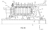
- FIG. 1B there is schematically depicted a brake mechanism 100 configured for use on a landing gear, such as, for example, each of the left main landing gear 12 and the right main landing gear 14 described above with reference to FIG. 1A .
- the brake mechanism is mounted relative to an axle 102 for use with a wheel 104 disposed on and configured to rotate about the axle 102 via one or more bearing assemblies 103.
- a central axis 112 extends through the axle 102 and defines a center of rotation of the wheel 104.
- a torque plate 114 (sometimes referred to as a torque tube) is aligned concentrically with the wheel 104, which is rotatable relative to the torque plate 114.
- the brake mechanism 100 includes a piston housing assembly 116, a pressure plate 118 disposed adjacent the piston housing assembly 116, an end plate 120 positioned a distal location from the piston housing assembly 116, and a plurality of rotor disks 122 interleaved with a plurality of stator disks 124 positioned intermediate the pressure plate 118 and the end plate 120.
- the pressure plate 118, the plurality of rotor disks 122, the plurality of stator disks 124 and the end plate 120 together form a brake stack 126 (or brake heat sink).
- the pressure plate 118, the end plate 120 and the plurality of stator disks 124 are connected to the torque plate 114 and remain rotationally stationary relative to the axle 102.
- the plurality of rotor disks 122 are connected to the wheel 104 and rotate relative to the pressure plate 118, the end plate 120 and the plurality of stator disks 124.
- the torque plate 114 may include an annular barrel or torque tube 128 and an annular plate or back leg 130.
- the back leg 130 is disposed at an end distal from the piston housing assembly 116 and may be made monolithic with the torque plate 114, as illustrated in FIG. 1B , or may be made as a separate annular piece and suitably connected to the torque tube 128.
- the torque plate 114 has a plurality of circumferentially spaced and axially extending splines 132 disposed on an outer surface of the torque tube 128.
- the plurality of stator disks 124 and the pressure plate 118 include notches or slots 134 on an inner periphery of the disks and the plate for engagement with the splines 132, such that each disk and the plate are axially slidable with respect to the torque tube 128.
- the end plate 120 is suitably connected to the back leg 130 of the torque plate 114 and is held non-rotatable, together with the plurality of stator disks 124 and the pressure plate 118, during a braking action.
- Torque plate 114 may extend through the end plate 120.
- Torque plate 114 may be an annular plate.
- the plurality of rotor disks 122 interleaved between the pressure plate 118, the end plate 120 and the plurality of stator disks 124, each have a plurality of circumferentially spaced notches or slots 136 along an outer periphery of each disk for engagement with a plurality of torque bars 138 that are secured to or made monolithic with an inner periphery of the wheel 104.
- An actuating mechanism for the brake mechanism 100 includes a plurality of piston assemblies, circumferentially spaced around a piston housing 140 (only one piston assembly is illustrated in FIG. 1B ).
- Each of the plurality of piston assemblies includes a piston 142 configured to apply a load against the pressure plate 118.
- the plurality of piston assemblies affect a braking action by urging the pressure plate 118 and the plurality of stator disks 124 into frictional engagement with the plurality of rotor disks 122 and against the end plate 120.
- Fluid or hydraulic pressure, mechanical springs or electric actuators, among other mechanisms, may be used to actuate the plurality of piston assemblies.
- the plurality of rotor disks 122 and the plurality of stator disks 124 are fabricated from various materials, such as ceramic matrix composites, that enable the brake disks to withstand and dissipate the heat generated during and following a braking action.
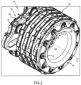
- FIG. 2 elements with like element numbering, as depicted in FIG. 1B , are intended to be the same and will not necessarily be repeated for the sake of clarity.
- a plurality of torque buttons 150 may be disposed between torque plate 114 and end plate 120. Torque buttons 150 may be circumferentially spaced around back leg 130. Torque buttons 150 may extend axially (i.e., parallel central axis 112) from back leg 130 towards piston housing 140. Each torque button 150 may extend into an axially adjacent (i.e., referring to a direction parallel to central axis 112) torque pocket 152 disposed in end plate 120. Each torque button 150 may be generally concentrically aligned with its associated torque pocket 152. In this regard, brake mechanism 100 may comprise a plurality of torque button 150 / torque pocket 152 pairs. In this manner, torsional forces may be transferred between end plate 120 and back leg 130. State differently, each torque button 150 and associated torque pocket 152 may create a mechanical interference that prevents rotation of end plate 120 about central axis 112 with respect to back leg 130.
- FIG. 3A and FIG. 3B elements with like element numbering, as depicted in FIG. 1B and FIG. 2 , are intended to be the same and will not necessarily be repeated for the sake of clarity.
- each torque button 150 may comprise a head portion 154 and a shaft portion 156 extending from the head portion 154.
- the shaft portion 156 and the head portion 154 are in concentric alignment.
- the head portion 154 is a round plate.
- the head portion 154 is an annular plate.
- Various forces e.g., torsional forces and/or radial forces
- Shaft portion 156 extends through aperture 158 disposed in back leg 130.
- a bushing 160 is provided to prevent wear of back leg 130 at aperture 158 during operation of the brake mechanism.
- bushing 160 may similarly be provided to prevent wear of torque button 150 during operation of the brake mechanism
- torque plate 114 is made of a material which is softer than that of torque button.
- torque plate 114 may be made of a first material such as titanium for example (e.g., cast titanium), and torque button 150 may be made of a second material such as steel for example. While the Brinell hardness of steel can vary with heat treatment and alloy composition, steel is typically harder than titanium. Thus, because the material of torque button 150 is generally tougher than the material of torque plate 114, torque button 150 may tend to deform torque plate 114 when forces are being transmitted therebetween.
- bushing 160 may be removably coupled between torque plate 114 and torque button 150 as a sacrificial part that can be replaced after bushing 160 becomes worn as desired.
- Bushing 160 may be made of any suitable material, such as a bronze alloy, such as nickel aluminum bronze.
- the material of the bushing 160 may be softer than the material of torque plate 114. In this manner, because the material of bushing 160 is softer than the material of torque plate 114, bushing 160 may protect torque plate 114 from becoming deformed by torque button 150.
- torque plate 114 may conversely be made of a material which is harder than that of torque button 150.
- torque button 150 may tend to be deformed by torque plate 114 when forces are transmitted therebetween.
- bushing 160 may be made of a material that is softer than the material of torque button 150 to protect torque button 150 from becoming deformed.
- bushing 160 is shaped to be a hollow cylindrical shaft.
- bushing 160 is shaped like a top hat (i.e., comprising a hollow cylindrical shaft with a radially outwardly extending flange disposed at an end thereof).
- Bushing 160 may be placed over the shaft portion 156. Stated differently, bushing 160 may be configured to receive shaft portion 156.
- Bushing 160 may be configured to circumferentially surround the shaft portion 156.
- Bushing 160 and shaft portion 156 may be in concentric alignment when bushing 160 is installed onto torque button 150.
- Bushing 160 may be received by aperture 158.
- the outer surface of bushing 160 may contact back leg 130 and the inner surface of bushing 160 may contact shaft portion 156.
- Head portion 154 of torque button 150 may be configured to extend at least partially into the torque pocket 152. Head portion 154 may be substantially flush with end plate 120 when head portion 154 is in the installed position in torque pocket 152. However, head portion 154 may extend at least partially into torque pocket 152 such that end plate 120 and head portion 154 are not substantially flush, in accordance with various embodiments.
- Shaft portion 156 may be configured to extend through aperture 158 of back leg 130. Aperture 158 may define a central axis 162. Central axis 162 may be substantially parallel to central axis 112 (see FIG. 2 ).
- FIG. 4 elements with like element numbering, as depicted in FIG. 1B through FIG. 3B , are intended to be the same and will not necessarily be repeated for the sake of clarity.
- shaft portion 156 comprises a through hole 164 configured to receive a pin 166 (see FIG. 3A ) for securing torque button 150 to torque plate 114.
- FIG. 5 elements with like element numbering, as depicted in FIG. 1B through FIG. 4 , are intended to be the same and will not necessarily be repeated for the sake of clarity.
- a total length 302 of bushing 160 may be less than a total length 304 of shaft portion 156.
- bushing 160 may be moved into aperture 158.
- bushing 160 is press fit into aperture 158.
- bushing 160 is placed into aperture 158 in a non-press fit design, wherein the outer diameter of bushing 160 is less than the inner diameter of aperture 158 such that bushing 160 is loosely disposed in aperture 158. In this manner, bushing 160 may be sufficiently held in place between the head portion 154 of torque button 150 and the terminus of shaft portion 156 opposite head portion 154; for example bushing 160 may be mechanically blocked from sliding off shaft portion 156 by pin 166 or the like.
- shaft portion 156 Before or after the bushing 160 is moved into aperture 158, shaft portion 156 may be moved into the bushing 160. In various embodiments, shaft portion 156 is press fit into bushing 160. End plate 120 may be moved over torque tube 128 (see FIG. 1B ). As the end plate 120 is slide (parallel central axis 112) over torque tube 128 towards back leg 130, head portion 154 may enter into torque pocket 152. End plate 120 may be moved towards back leg 130 until head portion 154 contacts the back surface of torque pocket 152.
- any of the method or process descriptions may be executed in any order and are not necessarily limited to the order presented.
- any reference to singular includes plural embodiments, and any reference to more than one component or step may include a singular embodiment or step.
- Elements and steps in the figures are illustrated for simplicity and clarity and have not necessarily been rendered according to any particular sequence. For example, steps that may be performed concurrently or in different order are only illustrated in the figures to help to improve understanding of embodiments of the present, representative invention.
- Any reference to attached, fixed, connected, or the like may include permanent, removable, temporary, partial, full and/or any other possible attachment option. Additionally, any reference to without contact (or similar phrases) may also include reduced contact or minimal contact. Surface shading lines may be used throughout the figures to denote different parts or areas, but not necessarily to denote the same or different materials. In some cases, reference coordinates may be specific to each figure.
- references to "one embodiment,” “an embodiment,” “various embodiments,” etc. indicate that the embodiment described may include a particular feature, structure, or characteristic, but every embodiment may not necessarily include the particular feature, structure, or characteristic. Moreover, such phrases are not necessarily referring to the same embodiment. Further, when a particular feature, structure, or characteristic is described in connection with an embodiment, it is submitted that it is within the knowledge of one skilled in the art to affect such feature, structure, or characteristic in connection with other embodiments, whether or not explicitly described. After reading the description, it will be apparent to one skilled in the relevant art(s) how to implement the disclosure in alternative embodiments.
Landscapes
- Engineering & Computer Science (AREA)
- General Engineering & Computer Science (AREA)
- Mechanical Engineering (AREA)
- Aviation & Aerospace Engineering (AREA)
- Braking Arrangements (AREA)
Claims (15)
- Bremsanordnung, umfassend:eine Drehmomentplatte (114), die ein Drehmomentrohr und einen hinteren Schenkel umfasst;eine Endplatte (140), die eine Drehmomenttasche umfasst;einen Drehmomentknopf (150), der einen Kopfabschnitt und einen Schaftabschnitt umfasst, wobei der Kopfabschnitt dazu konfiguriert ist, sich mindestens teilweise in die Drehmomenttasche zu erstrecken, und der Schaftabschnitt dazu konfiguriert ist, sich durch eine in dem hinteren Schenkel angeordnete Öffnung zu erstrecken; und gekennzeichnet durch eine Buchse, die dazu konfiguriert ist, lösbar zwischen dem Schaftabschnitt des Drehmomentknopfs (150) und dem hinteren Schenkel der Drehmomentplatte (114) gekoppelt zu sein.
- Bremsanordnung nach Anspruch 1, wobei das Drehmomentrohr eine ringförmige Trommel umfasst.
- Bremsanordnung nach Anspruch 2, wobei der hintere Schenkel eine ringförmige Platte umfasst.
- Bremsanordnung nach einem der vorhergehenden Ansprüche, wobei eine Außenfläche der Buchse dazu konfiguriert ist, den hinteren Schenkel zu berühren, und eine Innenfläche der Buchse dazu konfiguriert ist, den Schaftabschnitt des Drehmomentknopfs (150) zu berühren.
- Bremsanordnung nach Anspruch 4, wobei die Buchse ferner dazu konfiguriert ist, mindestens teilweise in die Öffnung aufgenommen zu werden.
- Bremsanordnung nach Anspruch 5, wobei die Buchse dazu konfiguriert ist, den Schaftabschnitt des Drehmomentknopfs (150) zu umgeben.
- Bremsanordnung nach einem der vorhergehenden Ansprüche, wobei eine Gesamtlänge der Buchse geringer als eine Gesamtlänge des Schaftabschnitts des Drehmomentknopfs (150) ist.
- Bremsanordnung nach einem der vorhergehenden Ansprüche, wobei die Drehmomentplatte (114) ein erstes Material umfasst und die Buchse ein zweites Material umfasst, wobei das zweite Material weicher als das erste Material ist und wobei das erste Material optional Titan ist.
- Drehmomentplattenanordnung, umfassend:eine Drehmomentplatte (114), die ein Drehmomentrohr umfasst, das eine erste Mittelachse und einen hinteren Schenkel definiert, wobei der hintere Schenkel eine Öffnung umfasst, die eine zweite Mittelachse definiert; und gekennzeichnet durcheine Buchse, die dazu konfiguriert ist, von der Öffnung aufgenommen zu werden; undeinen Drehmomentknopf (150), der einen Kopfabschnitt und einen Schaftabschnitt umfasst, wobei der Schaftabschnitt dazu konfiguriert ist, von der Buchse aufgenommen zu werden.
- Drehmomentplattenanordnung nach Anspruch 9, wobei die erste Mittelachse im Wesentlichen parallel zu der zweiten Mittelachse verläuft und/oder wobei das Drehmomentrohr eine ringförmige Trommel umfasst und/oder wobei der hintere Schenkel eine ringförmige Platte umfasst.
- Drehmomentplattenanordnung nach Anspruch 9 oder 10, wobei die Drehmomentplatte (114) ein erstes Material umfasst und die Buchse ein zweites Material umfasst, wobei das zweite Material weicher als das erste Material ist und wobei die Drehmomentplatte (114) optional aus Titan hergestellt ist.
- Drehmomentplattenanordnung nach einem der Ansprüche 9 bis 11, wobei der Drehmomentknopf (150) ein erstes Material umfasst und die Buchse ein zweites Material umfasst, wobei das zweite Material weicher als das erste Material ist.
- Drehmomentplattenanordnung nach einem der Ansprüche 9 bis 12, wobei der Schaftabschnitt des Drehmomentknopfs (150) ein Durchgangsloch zum Aufnehmen eines Stifts umfasst.
- Verfahren zum Zusammenbauen einer Bremsanordnung, dadurch gekennzeichnet, dass es Folgendes umfasst:Bewegen einer Buchse in eine Öffnung, die in einem hinteren Schenkel einer Drehmomentplatte (114) angeordnet ist;Bewegen eines Schaftabschnitts eines Drehmomentknopfs (150) in die Buchse; undBewegen einer Drehmomentplatte (140) über ein Drehmomentrohr der Drehmomentplatte.
- Verfahren nach Anspruch 14, ferner umfassend Bewegen eines Kopfabschnitts des Drehmomentknopfs (150) in eine Drehmomenttasche, die in der Endplatte angeordnet ist, und wobei das Bewegen der Drehmomentplatte (140) über das Drehmomentrohr optional das Bewegen der Drehmomentplatte (140) parallel zu einer Mittelachse der Drehmomentplatte beinhaltet und das Bewegen des Kopfabschnitts des Drehmomentknopfs (150) in die Drehmomenttasche als Reaktion auf das Bewegen der Drehmomentplatte (140) parallel zu der Mittelachse der Drehmomentplatte (114) durchgeführt wird.
Applications Claiming Priority (1)
| Application Number | Priority Date | Filing Date | Title |
|---|---|---|---|
| US17/504,076 US11834159B2 (en) | 2021-10-18 | 2021-10-18 | Torque button bushing |
Publications (2)
| Publication Number | Publication Date |
|---|---|
| EP4166808A1 EP4166808A1 (de) | 2023-04-19 |
| EP4166808B1 true EP4166808B1 (de) | 2024-09-11 |
Family
ID=83693020
Family Applications (1)
| Application Number | Title | Priority Date | Filing Date |
|---|---|---|---|
| EP22201444.1A Active EP4166808B1 (de) | 2021-10-18 | 2022-10-13 | Drehmomentknopfbuchse |
Country Status (2)
| Country | Link |
|---|---|
| US (1) | US11834159B2 (de) |
| EP (1) | EP4166808B1 (de) |
Families Citing this family (1)
| Publication number | Priority date | Publication date | Assignee | Title |
|---|---|---|---|---|
| US12595830B2 (en) * | 2023-03-24 | 2026-04-07 | Honeywell International Inc. | Torque pad attachment assembly |
Family Cites Families (22)
| Publication number | Priority date | Publication date | Assignee | Title |
|---|---|---|---|---|
| US5255761A (en) * | 1989-12-21 | 1993-10-26 | The B. F. Goodrich Company | Aircraft brake |
| US5494138A (en) * | 1994-10-14 | 1996-02-27 | Alliedsignal, Inc. | Aircraft brake torque transfer assembly |
| US5558186A (en) * | 1995-05-24 | 1996-09-24 | The Bfgoodrich Company | Friction disk with renewable wear faces |
| FR2755094B1 (fr) * | 1996-10-31 | 1998-11-27 | Messier Bugatti | Agencement de disques de frein en carbone pour unite de freinage d'aeronef, et procede d'assemblage de disques selon un tel agencement |
| US5908091A (en) * | 1997-08-13 | 1999-06-01 | Alliedsignal Inc. | Multi-disc brake with vibration damping |
| US6003954A (en) | 1997-08-25 | 1999-12-21 | Aircraft Braking Systems Corporation | Aircraft wheel and beam key attachment |
| US7047596B2 (en) * | 2003-12-09 | 2006-05-23 | Sikorsky Aircraft Corp. | Structural bushing application for highly loaded composites lugs |
| US8661683B2 (en) * | 2006-08-29 | 2014-03-04 | The Boeing Company | Method and apparatus for preventing lightning strike damage to a structural component |
| US8616344B2 (en) * | 2007-05-21 | 2013-12-31 | Goodrich Corporation | Asymmetrical brake torque plate back leg |
| FR2917065B1 (fr) * | 2007-06-05 | 2010-05-21 | Messier Bugatti | Ensemble de roue et frein pour aeronef |
| ES2342703B1 (es) | 2008-06-27 | 2011-05-25 | Aernnova Engineering Solutions | Mecanismo de cierre y bloqueo para puerta de mamparo. |
| US8932022B2 (en) * | 2012-02-03 | 2015-01-13 | Pratt & Whitney Canada Corp. | Fastening system for fan and shaft interconnection |
| FR3013412B1 (fr) * | 2013-11-21 | 2015-12-25 | Messier Bugatti Dowty | Procede de renovation et d’utilisation de disques de frein de type stator arriere a plots, disque assemble et pile de disques correspondante. |
| CN110182373B (zh) * | 2015-01-07 | 2023-01-10 | 洛德公司 | 用于飞行器发动机安装架的轴承组件 |
| US9670975B1 (en) | 2015-12-21 | 2017-06-06 | Goodrich Corporation | Torque tube damping devices and assemblies |
| US10274034B2 (en) | 2017-07-12 | 2019-04-30 | Goodrich Corporation | Wear liner with integrated torque button |
| US10330163B2 (en) * | 2017-10-16 | 2019-06-25 | Goodrich Corporation | Shield attachment method and device |
| US10941823B2 (en) | 2017-11-27 | 2021-03-09 | Goodrich Corporation | Segmented wear liner |
| US10408290B2 (en) | 2018-02-08 | 2019-09-10 | Goodrich Corporation | Insulated torque plate foot assembly |
| US10677278B2 (en) | 2018-03-15 | 2020-06-09 | Goodrich Corporation | Torque button lock clip |
| US10766609B2 (en) * | 2018-06-28 | 2020-09-08 | Goodrich Corporation | Torque bar retention for wheel assemblies |
| US20200096064A1 (en) | 2018-09-26 | 2020-03-26 | Goodrich Corporation | Friction discs with angled stator lugs |
-
2021
- 2021-10-18 US US17/504,076 patent/US11834159B2/en active Active
-
2022
- 2022-10-13 EP EP22201444.1A patent/EP4166808B1/de active Active
Also Published As
| Publication number | Publication date |
|---|---|
| US20230124506A1 (en) | 2023-04-20 |
| EP4166808A1 (de) | 2023-04-19 |
| US11834159B2 (en) | 2023-12-05 |
Similar Documents
| Publication | Publication Date | Title |
|---|---|---|
| EP3767125B1 (de) | Hitzeschildhalterung und verfahren | |
| EP3670955B1 (de) | Hitzeschildhalterung und verfahren | |
| EP3480072B1 (de) | Abschirmungsanbringungsvorrichtung | |
| EP3647622B1 (de) | Segmentierter hitzeschild mit reduzierter zwischenschichtwärmeleitung | |
| EP4166808B1 (de) | Drehmomentknopfbuchse | |
| EP3418601B1 (de) | Lamellenbremsanordnung mit hubbegrenzungsstift | |
| EP3726087B1 (de) | Mehrschichtiger kolbenisolator für hydraulischen bremszylinder | |
| EP4283154B1 (de) | Statorklammer für bremsanordnung | |
| EP3187746A1 (de) | Plattenanordnungen mit schwimmenden verschleissverkleidungen für mehrscheibenbremssystem und verfahren zur verringerung der vibrationen in einem mehrscheibenbremssystem | |
| EP4299942B1 (de) | Ausfallsicherer kolbendruckweg | |
| EP4209691B1 (de) | Gegabelte hitzeschildbefestigungsklammer | |
| EP3441637B1 (de) | Unterschiedliche drehmomentplattengehäusedicke und verfahren zur schadensminimierung in einer bremsanlage | |
| EP4306821A1 (de) | Wärmehaltender abschirmverschluss | |
| EP4321768B1 (de) | Konischer drehmomentplattenzylinder zur verbesserung der dynamischen stabilität | |
| EP4261431B1 (de) | Geschlitzter drehmomentplattenzylinder | |
| EP4414581A1 (de) | Verwendung von profilierter reaktionsfläche bei hybriden drehmomentbalkenanwendungen | |
| EP3798463B1 (de) | Kohlenstoffbremsstapelanordnung für verbesserte lebensdauer |
Legal Events
| Date | Code | Title | Description |
|---|---|---|---|
| PUAI | Public reference made under article 153(3) epc to a published international application that has entered the european phase |
Free format text: ORIGINAL CODE: 0009012 |
|
| STAA | Information on the status of an ep patent application or granted ep patent |
Free format text: STATUS: THE APPLICATION HAS BEEN PUBLISHED |
|
| AK | Designated contracting states |
Kind code of ref document: A1 Designated state(s): AL AT BE BG CH CY CZ DE DK EE ES FI FR GB GR HR HU IE IS IT LI LT LU LV MC ME MK MT NL NO PL PT RO RS SE SI SK SM TR |
|
| STAA | Information on the status of an ep patent application or granted ep patent |
Free format text: STATUS: REQUEST FOR EXAMINATION WAS MADE |
|
| P01 | Opt-out of the competence of the unified patent court (upc) registered |
Effective date: 20230922 |
|
| 17P | Request for examination filed |
Effective date: 20231018 |
|
| RBV | Designated contracting states (corrected) |
Designated state(s): AL AT BE BG CH CY CZ DE DK EE ES FI FR GB GR HR HU IE IS IT LI LT LU LV MC ME MK MT NL NO PL PT RO RS SE SI SK SM TR |
|
| GRAP | Despatch of communication of intention to grant a patent |
Free format text: ORIGINAL CODE: EPIDOSNIGR1 |
|
| STAA | Information on the status of an ep patent application or granted ep patent |
Free format text: STATUS: GRANT OF PATENT IS INTENDED |
|
| INTG | Intention to grant announced |
Effective date: 20240418 |
|
| GRAS | Grant fee paid |
Free format text: ORIGINAL CODE: EPIDOSNIGR3 |
|
| GRAA | (expected) grant |
Free format text: ORIGINAL CODE: 0009210 |
|
| STAA | Information on the status of an ep patent application or granted ep patent |
Free format text: STATUS: THE PATENT HAS BEEN GRANTED |
|
| AK | Designated contracting states |
Kind code of ref document: B1 Designated state(s): AL AT BE BG CH CY CZ DE DK EE ES FI FR GB GR HR HU IE IS IT LI LT LU LV MC ME MK MT NL NO PL PT RO RS SE SI SK SM TR |
|
| REG | Reference to a national code |
Ref country code: GB Ref legal event code: FG4D |
|
| REG | Reference to a national code |
Ref country code: CH Ref legal event code: EP |
|
| REG | Reference to a national code |
Ref country code: DE Ref legal event code: R096 Ref document number: 602022006020 Country of ref document: DE |
|
| REG | Reference to a national code |
Ref country code: IE Ref legal event code: FG4D |
|
| REG | Reference to a national code |
Ref country code: LT Ref legal event code: MG9D |
|
| PG25 | Lapsed in a contracting state [announced via postgrant information from national office to epo] |
Ref country code: NO Free format text: LAPSE BECAUSE OF FAILURE TO SUBMIT A TRANSLATION OF THE DESCRIPTION OR TO PAY THE FEE WITHIN THE PRESCRIBED TIME-LIMIT Effective date: 20241211 |
|
| REG | Reference to a national code |
Ref country code: NL Ref legal event code: MP Effective date: 20240911 |
|
| PG25 | Lapsed in a contracting state [announced via postgrant information from national office to epo] |
Ref country code: GR Free format text: LAPSE BECAUSE OF FAILURE TO SUBMIT A TRANSLATION OF THE DESCRIPTION OR TO PAY THE FEE WITHIN THE PRESCRIBED TIME-LIMIT Effective date: 20241212 Ref country code: FI Free format text: LAPSE BECAUSE OF FAILURE TO SUBMIT A TRANSLATION OF THE DESCRIPTION OR TO PAY THE FEE WITHIN THE PRESCRIBED TIME-LIMIT Effective date: 20240911 |
|
| PG25 | Lapsed in a contracting state [announced via postgrant information from national office to epo] |
Ref country code: BG Free format text: LAPSE BECAUSE OF FAILURE TO SUBMIT A TRANSLATION OF THE DESCRIPTION OR TO PAY THE FEE WITHIN THE PRESCRIBED TIME-LIMIT Effective date: 20240911 |
|
| PG25 | Lapsed in a contracting state [announced via postgrant information from national office to epo] |
Ref country code: LV Free format text: LAPSE BECAUSE OF FAILURE TO SUBMIT A TRANSLATION OF THE DESCRIPTION OR TO PAY THE FEE WITHIN THE PRESCRIBED TIME-LIMIT Effective date: 20240911 |
|
| PG25 | Lapsed in a contracting state [announced via postgrant information from national office to epo] |
Ref country code: HR Free format text: LAPSE BECAUSE OF FAILURE TO SUBMIT A TRANSLATION OF THE DESCRIPTION OR TO PAY THE FEE WITHIN THE PRESCRIBED TIME-LIMIT Effective date: 20240911 |
|
| PG25 | Lapsed in a contracting state [announced via postgrant information from national office to epo] |
Ref country code: ES Free format text: LAPSE BECAUSE OF FAILURE TO SUBMIT A TRANSLATION OF THE DESCRIPTION OR TO PAY THE FEE WITHIN THE PRESCRIBED TIME-LIMIT Effective date: 20240911 Ref country code: RS Free format text: LAPSE BECAUSE OF FAILURE TO SUBMIT A TRANSLATION OF THE DESCRIPTION OR TO PAY THE FEE WITHIN THE PRESCRIBED TIME-LIMIT Effective date: 20241211 |
|
| PG25 | Lapsed in a contracting state [announced via postgrant information from national office to epo] |
Ref country code: RS Free format text: LAPSE BECAUSE OF FAILURE TO SUBMIT A TRANSLATION OF THE DESCRIPTION OR TO PAY THE FEE WITHIN THE PRESCRIBED TIME-LIMIT Effective date: 20241211 Ref country code: NO Free format text: LAPSE BECAUSE OF FAILURE TO SUBMIT A TRANSLATION OF THE DESCRIPTION OR TO PAY THE FEE WITHIN THE PRESCRIBED TIME-LIMIT Effective date: 20241211 Ref country code: LV Free format text: LAPSE BECAUSE OF FAILURE TO SUBMIT A TRANSLATION OF THE DESCRIPTION OR TO PAY THE FEE WITHIN THE PRESCRIBED TIME-LIMIT Effective date: 20240911 Ref country code: HR Free format text: LAPSE BECAUSE OF FAILURE TO SUBMIT A TRANSLATION OF THE DESCRIPTION OR TO PAY THE FEE WITHIN THE PRESCRIBED TIME-LIMIT Effective date: 20240911 Ref country code: GR Free format text: LAPSE BECAUSE OF FAILURE TO SUBMIT A TRANSLATION OF THE DESCRIPTION OR TO PAY THE FEE WITHIN THE PRESCRIBED TIME-LIMIT Effective date: 20241212 Ref country code: FI Free format text: LAPSE BECAUSE OF FAILURE TO SUBMIT A TRANSLATION OF THE DESCRIPTION OR TO PAY THE FEE WITHIN THE PRESCRIBED TIME-LIMIT Effective date: 20240911 Ref country code: ES Free format text: LAPSE BECAUSE OF FAILURE TO SUBMIT A TRANSLATION OF THE DESCRIPTION OR TO PAY THE FEE WITHIN THE PRESCRIBED TIME-LIMIT Effective date: 20240911 Ref country code: BG Free format text: LAPSE BECAUSE OF FAILURE TO SUBMIT A TRANSLATION OF THE DESCRIPTION OR TO PAY THE FEE WITHIN THE PRESCRIBED TIME-LIMIT Effective date: 20240911 |
|
| REG | Reference to a national code |
Ref country code: AT Ref legal event code: MK05 Ref document number: 1722931 Country of ref document: AT Kind code of ref document: T Effective date: 20240911 |
|
| PG25 | Lapsed in a contracting state [announced via postgrant information from national office to epo] |
Ref country code: NL Free format text: LAPSE BECAUSE OF FAILURE TO SUBMIT A TRANSLATION OF THE DESCRIPTION OR TO PAY THE FEE WITHIN THE PRESCRIBED TIME-LIMIT Effective date: 20240911 |
|
| PG25 | Lapsed in a contracting state [announced via postgrant information from national office to epo] |
Ref country code: IS Free format text: LAPSE BECAUSE OF FAILURE TO SUBMIT A TRANSLATION OF THE DESCRIPTION OR TO PAY THE FEE WITHIN THE PRESCRIBED TIME-LIMIT Effective date: 20250111 Ref country code: PT Free format text: LAPSE BECAUSE OF FAILURE TO SUBMIT A TRANSLATION OF THE DESCRIPTION OR TO PAY THE FEE WITHIN THE PRESCRIBED TIME-LIMIT Effective date: 20250113 |
|
| PG25 | Lapsed in a contracting state [announced via postgrant information from national office to epo] |
Ref country code: SM Free format text: LAPSE BECAUSE OF FAILURE TO SUBMIT A TRANSLATION OF THE DESCRIPTION OR TO PAY THE FEE WITHIN THE PRESCRIBED TIME-LIMIT Effective date: 20240911 Ref country code: RO Free format text: LAPSE BECAUSE OF FAILURE TO SUBMIT A TRANSLATION OF THE DESCRIPTION OR TO PAY THE FEE WITHIN THE PRESCRIBED TIME-LIMIT Effective date: 20240911 |
|
| PG25 | Lapsed in a contracting state [announced via postgrant information from national office to epo] |
Ref country code: AT Free format text: LAPSE BECAUSE OF FAILURE TO SUBMIT A TRANSLATION OF THE DESCRIPTION OR TO PAY THE FEE WITHIN THE PRESCRIBED TIME-LIMIT Effective date: 20240911 Ref country code: EE Free format text: LAPSE BECAUSE OF FAILURE TO SUBMIT A TRANSLATION OF THE DESCRIPTION OR TO PAY THE FEE WITHIN THE PRESCRIBED TIME-LIMIT Effective date: 20240911 |
|
| PG25 | Lapsed in a contracting state [announced via postgrant information from national office to epo] |
Ref country code: PL Free format text: LAPSE BECAUSE OF FAILURE TO SUBMIT A TRANSLATION OF THE DESCRIPTION OR TO PAY THE FEE WITHIN THE PRESCRIBED TIME-LIMIT Effective date: 20240911 Ref country code: CZ Free format text: LAPSE BECAUSE OF FAILURE TO SUBMIT A TRANSLATION OF THE DESCRIPTION OR TO PAY THE FEE WITHIN THE PRESCRIBED TIME-LIMIT Effective date: 20240911 |
|
| PG25 | Lapsed in a contracting state [announced via postgrant information from national office to epo] |
Ref country code: IT Free format text: LAPSE BECAUSE OF FAILURE TO SUBMIT A TRANSLATION OF THE DESCRIPTION OR TO PAY THE FEE WITHIN THE PRESCRIBED TIME-LIMIT Effective date: 20240911 Ref country code: SK Free format text: LAPSE BECAUSE OF FAILURE TO SUBMIT A TRANSLATION OF THE DESCRIPTION OR TO PAY THE FEE WITHIN THE PRESCRIBED TIME-LIMIT Effective date: 20240911 |
|
| REG | Reference to a national code |
Ref country code: DE Ref legal event code: R097 Ref document number: 602022006020 Country of ref document: DE |
|
| PG25 | Lapsed in a contracting state [announced via postgrant information from national office to epo] |
Ref country code: MC Free format text: LAPSE BECAUSE OF FAILURE TO SUBMIT A TRANSLATION OF THE DESCRIPTION OR TO PAY THE FEE WITHIN THE PRESCRIBED TIME-LIMIT Effective date: 20240911 |
|
| PG25 | Lapsed in a contracting state [announced via postgrant information from national office to epo] |
Ref country code: DK Free format text: LAPSE BECAUSE OF FAILURE TO SUBMIT A TRANSLATION OF THE DESCRIPTION OR TO PAY THE FEE WITHIN THE PRESCRIBED TIME-LIMIT Effective date: 20240911 |
|
| PG25 | Lapsed in a contracting state [announced via postgrant information from national office to epo] |
Ref country code: LU Free format text: LAPSE BECAUSE OF NON-PAYMENT OF DUE FEES Effective date: 20241013 Ref country code: BE Free format text: LAPSE BECAUSE OF NON-PAYMENT OF DUE FEES Effective date: 20241031 |
|
| PLBE | No opposition filed within time limit |
Free format text: ORIGINAL CODE: 0009261 |
|
| STAA | Information on the status of an ep patent application or granted ep patent |
Free format text: STATUS: NO OPPOSITION FILED WITHIN TIME LIMIT |
|
| REG | Reference to a national code |
Ref country code: BE Ref legal event code: MM Effective date: 20241031 |
|
| 26N | No opposition filed |
Effective date: 20250612 |
|
| PG25 | Lapsed in a contracting state [announced via postgrant information from national office to epo] |
Ref country code: SE Free format text: LAPSE BECAUSE OF FAILURE TO SUBMIT A TRANSLATION OF THE DESCRIPTION OR TO PAY THE FEE WITHIN THE PRESCRIBED TIME-LIMIT Effective date: 20240911 |
|
| PGFP | Annual fee paid to national office [announced via postgrant information from national office to epo] |
Ref country code: FR Payment date: 20250923 Year of fee payment: 4 |
|
| PG25 | Lapsed in a contracting state [announced via postgrant information from national office to epo] |
Ref country code: IE Free format text: LAPSE BECAUSE OF NON-PAYMENT OF DUE FEES Effective date: 20241013 |
|
| PGFP | Annual fee paid to national office [announced via postgrant information from national office to epo] |
Ref country code: DE Payment date: 20250923 Year of fee payment: 4 |
|
| PG25 | Lapsed in a contracting state [announced via postgrant information from national office to epo] |
Ref country code: CY Free format text: LAPSE BECAUSE OF FAILURE TO SUBMIT A TRANSLATION OF THE DESCRIPTION OR TO PAY THE FEE WITHIN THE PRESCRIBED TIME-LIMIT; INVALID AB INITIO Effective date: 20221013 |
|
| PG25 | Lapsed in a contracting state [announced via postgrant information from national office to epo] |
Ref country code: HU Free format text: LAPSE BECAUSE OF FAILURE TO SUBMIT A TRANSLATION OF THE DESCRIPTION OR TO PAY THE FEE WITHIN THE PRESCRIBED TIME-LIMIT; INVALID AB INITIO Effective date: 20221013 |