EP3798463B1 - Kohlenstoffbremsstapelanordnung für verbesserte lebensdauer - Google Patents
Kohlenstoffbremsstapelanordnung für verbesserte lebensdauer Download PDFInfo
- Publication number
- EP3798463B1 EP3798463B1 EP19216082.8A EP19216082A EP3798463B1 EP 3798463 B1 EP3798463 B1 EP 3798463B1 EP 19216082 A EP19216082 A EP 19216082A EP 3798463 B1 EP3798463 B1 EP 3798463B1
- Authority
- EP
- European Patent Office
- Prior art keywords
- stator
- spring
- rotor
- cmc
- brake system
- Prior art date
- Legal status (The legal status is an assumption and is not a legal conclusion. Google has not performed a legal analysis and makes no representation as to the accuracy of the status listed.)
- Active
Links
Images


Classifications
-
- F—MECHANICAL ENGINEERING; LIGHTING; HEATING; WEAPONS; BLASTING
- F16—ENGINEERING ELEMENTS AND UNITS; GENERAL MEASURES FOR PRODUCING AND MAINTAINING EFFECTIVE FUNCTIONING OF MACHINES OR INSTALLATIONS; THERMAL INSULATION IN GENERAL
- F16D—COUPLINGS FOR TRANSMITTING ROTATION; CLUTCHES; BRAKES
- F16D55/00—Brakes with substantially-radial braking surfaces pressed together in axial direction, e.g. disc brakes
- F16D55/24—Brakes with substantially-radial braking surfaces pressed together in axial direction, e.g. disc brakes with a plurality of axially-movable discs, lamellae, or pads, pressed from one side towards an axially-located member
- F16D55/26—Brakes with substantially-radial braking surfaces pressed together in axial direction, e.g. disc brakes with a plurality of axially-movable discs, lamellae, or pads, pressed from one side towards an axially-located member without self-tightening action
- F16D55/36—Brakes with a plurality of rotating discs all lying side by side
-
- B—PERFORMING OPERATIONS; TRANSPORTING
- B64—AIRCRAFT; AVIATION; COSMONAUTICS
- B64C—AEROPLANES; HELICOPTERS
- B64C25/00—Alighting gear
- B64C25/32—Alighting gear characterised by elements which contact the ground or similar surface
- B64C25/42—Arrangement or adaptation of brakes
-
- B—PERFORMING OPERATIONS; TRANSPORTING
- B64—AIRCRAFT; AVIATION; COSMONAUTICS
- B64C—AEROPLANES; HELICOPTERS
- B64C25/00—Alighting gear
- B64C25/32—Alighting gear characterised by elements which contact the ground or similar surface
- B64C25/42—Arrangement or adaptation of brakes
- B64C25/44—Actuating mechanisms
-
- F—MECHANICAL ENGINEERING; LIGHTING; HEATING; WEAPONS; BLASTING
- F16—ENGINEERING ELEMENTS AND UNITS; GENERAL MEASURES FOR PRODUCING AND MAINTAINING EFFECTIVE FUNCTIONING OF MACHINES OR INSTALLATIONS; THERMAL INSULATION IN GENERAL
- F16D—COUPLINGS FOR TRANSMITTING ROTATION; CLUTCHES; BRAKES
- F16D65/00—Parts or details
- F16D65/14—Actuating mechanisms for brakes; Means for initiating operation at a predetermined position
- F16D65/16—Actuating mechanisms for brakes; Means for initiating operation at a predetermined position arranged in or on the brake
- F16D65/18—Actuating mechanisms for brakes; Means for initiating operation at a predetermined position arranged in or on the brake adapted for drawing members together, e.g. for disc brakes
- F16D65/186—Actuating mechanisms for brakes; Means for initiating operation at a predetermined position arranged in or on the brake adapted for drawing members together, e.g. for disc brakes with full-face force-applying member, e.g. annular
-
- F—MECHANICAL ENGINEERING; LIGHTING; HEATING; WEAPONS; BLASTING
- F16—ENGINEERING ELEMENTS AND UNITS; GENERAL MEASURES FOR PRODUCING AND MAINTAINING EFFECTIVE FUNCTIONING OF MACHINES OR INSTALLATIONS; THERMAL INSULATION IN GENERAL
- F16D—COUPLINGS FOR TRANSMITTING ROTATION; CLUTCHES; BRAKES
- F16D55/00—Brakes with substantially-radial braking surfaces pressed together in axial direction, e.g. disc brakes
- F16D2055/0004—Parts or details of disc brakes
- F16D2055/0058—Fully lined, i.e. braking surface extending over the entire disc circumference
-
- F—MECHANICAL ENGINEERING; LIGHTING; HEATING; WEAPONS; BLASTING
- F16—ENGINEERING ELEMENTS AND UNITS; GENERAL MEASURES FOR PRODUCING AND MAINTAINING EFFECTIVE FUNCTIONING OF MACHINES OR INSTALLATIONS; THERMAL INSULATION IN GENERAL
- F16D—COUPLINGS FOR TRANSMITTING ROTATION; CLUTCHES; BRAKES
- F16D2125/00—Components of actuators
- F16D2125/18—Mechanical mechanisms
- F16D2125/58—Mechanical mechanisms transmitting linear movement
- F16D2125/582—Flexible element, e.g. spring, other than the main force generating element
- F16D2125/585—Flexible element, e.g. spring, other than the main force generating element arranged in parallel with a force-applying member
-
- F—MECHANICAL ENGINEERING; LIGHTING; HEATING; WEAPONS; BLASTING
- F16—ENGINEERING ELEMENTS AND UNITS; GENERAL MEASURES FOR PRODUCING AND MAINTAINING EFFECTIVE FUNCTIONING OF MACHINES OR INSTALLATIONS; THERMAL INSULATION IN GENERAL
- F16D—COUPLINGS FOR TRANSMITTING ROTATION; CLUTCHES; BRAKES
- F16D2200/00—Materials; Production methods therefor
- F16D2200/0034—Materials; Production methods therefor non-metallic
- F16D2200/0039—Ceramics
- F16D2200/0047—Ceramic composite, e.g. C/C composite infiltrated with Si or B, or ceramic matrix infiltrated with metal
-
- F—MECHANICAL ENGINEERING; LIGHTING; HEATING; WEAPONS; BLASTING
- F16—ENGINEERING ELEMENTS AND UNITS; GENERAL MEASURES FOR PRODUCING AND MAINTAINING EFFECTIVE FUNCTIONING OF MACHINES OR INSTALLATIONS; THERMAL INSULATION IN GENERAL
- F16D—COUPLINGS FOR TRANSMITTING ROTATION; CLUTCHES; BRAKES
- F16D2200/00—Materials; Production methods therefor
- F16D2200/0034—Materials; Production methods therefor non-metallic
- F16D2200/0052—Carbon
Definitions
- the present invention relates to carbon-carbon (carbon) and ceramic matrix composite (CMC) braking systems, and more specifically to improve wear life for carbon and CMC friction disks of aircraft braking systems.
- Aircraft carbon and CMC brake systems typically employ a series of friction disks forced into contact with each other to stop the aircraft.
- Friction disks splined to a non-rotating wheel axle are interspersed with friction disks splined to the rotating wheel.
- the friction disks withstand and dissipate the heat generated from contact between one another during braking.
- carbon friction disks in particular are colder and quicker to wear than when the friction disks are hotter.
- EP 0 138 345 relates to a disc brake unit comprising a multiple discs brake assembly.
- the brake stack comprises a first stator having a first stator radially inner end; a first rotor disposed axially adjacent to the first stator, the first rotor having a first rotor radially inner end; a second stator disposed axially adjacent to the first rotor; and a first spring disposed axially between the first stator and the second stator and radially between the first stator radially inner end and the first rotor radially inner end.
- the first spring may be a wave spring.
- the brake stack further comprises a pressure plate disposed at a proximal end of the brake stack, wherein the first spring is configured to partially compress when a force is applied to the pressure plate that is less than a threshold force.
- a first stator axial face of the first stator is separated from a first rotor axial face of the first rotor when the first spring is partially compressed.
- the threshold force may correspond to a threshold pressure between 600 psi (4.14 MPa) and 800 psi (5.52 MPa).
- the brake stack further comprises a pressure plate disposed at a proximal end of the brake stack, wherein the first spring is configured to fully compress when a force is applied to the pressure plate that is greater than a threshold force.
- a first stator axial face of the first stator may contact a first rotor axial face of the first rotor when the first spring is fully compressed.
- the brake stack may further comprisee: a second rotor disposed axially adjacent to the second stator, the second rotor having a second rotor radially inner end; a third stator disposed axially adjacent to the second rotor; and a second spring disposed axially between the second stator and the third stator and radially between a second stator radially inner end of the second stator and the second rotor radially inner end.
- the second spring may be a second wave spring.
- the CMC brake system comprises: a brake stack comprising pressure plate; an end plate disposed distal to the pressure plate; a plurality of rotors disposed between the pressure plate and the end plate; a plurality of stators disposed between the pressure plate and the end plate, the plurality of stators interleaved between the plurality of rotors; a first portion of disks having no spring, a second portion of disks having at least a first spring disposed axially between a first stator in the plurality of stators and an adjacent stator in the plurality of stators, the first spring disposed radially inward of a first rotor in the plurality of rotors, wherein the first spring is configured to partially compress when a force is applied to the pressure plate that is less than a threshold force; wherein a first stator axial face of the first stator is separated from a first rotor axial
- the first spring comprises a wave spring.
- the threshold force may correspond to a threshold pressure between 600 psi (4.14 MPa) and 800 psi (5.52 MPa).
- the first spring may be configured to fully compress when a force is applied to the pressure plate that is greater than a threshold force.
- a first stator axial face of the first stator may contact a first rotor axial face of the first rotor when the first spring is fully compressed.
- the multi-disk brake system may further comprise a plurality of the first spring. The plurality of the first spring may be disposed circumferentially about the first stator.
- a method of using a multi-disk carbon and ceramic matrix composite (CMC) brake system according to the invention is defined in claim 7.
- the method comprises: applying a force to a pressure plate of the multi-disk carbon and CMC brake system comprising a brake stack; compressing a spring between a first stator and a second stator; and using a portion of disks in the brake stack if the force is less than a threshold force; and using all disks in the brake stack if the force is greater than the threshold force.
- CMC ceramic matrix composite
- a first component that is "radially outward" of a second component means that the first component is positioned at a greater distance away from the common axis than the second component.
- a first component that is “radially inward” of a second component means that the first component is positioned closer to the common axis than the second component.
- a first component that is radially inward of a second component rotates through a circumferentially shorter path than the second component.
- distal refers to the direction outward, or generally, away from a reference component.
- proximal and/or “proximate” refer to a direction inward, or generally, towards the reference component.
- the multi-disk carbon and CMC brake system includes a plurality of rotors interleaved between a plurality of stators, a pressure plate at a proximal end, an end plate at a distal end, and at least one spring.
- the spring is disposed between a first stator and a second stator and radially inward of a rotor. The spring is configured to allow a portion of the rotors and stators to supply the braking when a force applied to the pressure plate is below a threshold force.
- the spring is configured to allow all the rotors and stators to supply the braking when a force applied to the pressure plate is above the threshold force.
- Carbon composite disks may wear quicker when they are cold.
- the disks being used may heat up more quickly increasing the life of the disks being used and/or reducing the number of cold taxis experienced.
- the second portion of disks may have significantly increased life. As such, at overhaul, the first portion of disks may be replaced, and the second portion of disks may remain, reducing cost and time at overhaul.
- a multi-disk carbon and CMC brake system 20 is illustrated according to various examples.
- the system may include a wheel 10 supported for rotation around axle 12 by bearings 14.
- Axle 12 defines an axis of multi-disk carbon and CMC brake system 20 and the various components thereof described herein, and any reference to the terms axis and axial may include an axis of rotation defined by axle 12 or a dimension parallel to such axis.
- Wheel 10 includes rims 16 for supporting a tire, and a series of axially extending rotor splines 18 (one shown). Rotation of wheel 10 is modulated by multi-disk carbon and CMC brake system 20.
- Multi-disk carbon and CMC brake system 20 includes torque flange 22, torque tube 24, a plurality of pistons/actuators 26 (one shown), pressure plate 30, and end plate 32.
- Torque tube 24 may be an elongated annular structure that includes reaction plate 34 and a series of axially extending stator splines 36 (one shown). Reaction plate 34 and stator splines 36 may be integral with torque tube 24, as shown in FIG. 1 , or attached as separate components.
- Multi-disk carbon and CMC brake system 20 also includes a plurality of friction disks 38.
- Each friction disk 38 may comprise a solid disk, split disk or friction wear liners and core.
- the plurality of friction disks 38 includes at least one friction wear liners with a non-rotatable core, also known as a stator 40, and at least one friction disk wear liners with a rotatable core, also known as a rotor 42.
- Stators 40 and rotors 42 are located adjacent to one another in multi-disk brake system 20, forming a plurality of adjacent stator-rotor pairs.
- Stators 40 may comprise a stator core 48 and wear liners 50.
- Rotors 42 may comprise a rotor core 49 and wear liners 50.
- Each friction disk 38 includes an attachment structure.
- each of the four stators 40 includes a plurality of stator lugs 44 at circumferentially spaced positions around stator 40 as an attachment structure.
- each of the five rotors 42 includes a plurality of rotor lugs 46 at circumferentially spaced positions around rotor 42 as an attachment structure.
- pressure plate 30, end plate 32, and friction disks 38 are all annular structures made at least partially from a carbon or CMC composite material.
- Torque flange 22 may be mounted to axle 12. Torque tube 24 is bolted to torque flange 22 such that reaction plate 34 is near an axial center of wheel 10. End plate 32 is connected to a surface of reaction plate 34 facing axially inward. Thus, end plate 32 is non-rotatable by virtue of its connection to torque tube 24. Stator splines 36 support pressure plate 30 so that pressure plate 30 is also non-rotatable. Stator splines 36 also support stators 40 via stator cores 48. Stator cores 48 engage stator splines 36 with gaps formed between stator lugs 44. Similarly, rotors 42 engage rotor splines 18 via rotor core 49 with gaps formed between rotor lugs 46. Thus, rotor cores 49 of rotors 42 are rotatable by virtue of their engagement with rotor splines 18 of wheel 10.
- rotors 42 with rotor cores 49 are arranged with end plate 32 on one end, pressure plate 30 on the other end, and stators 40 with stator cores 48 interleaved so that rotors 42 with rotor cores 49 are directly or indirectly adjacent to non-rotatable friction components.
- Pistons/actuators 26 are connected to torque flange 22 at circumferentially spaced positions around torque flange 22. Pistons/actuators 26 face axially toward wheel 10 and contact a side of pressure plate 30 opposite friction disks 38. Pistons/actuators 26 may be powered electrically, hydraulically, or pneumatically.
- a force towards reaction plate 34, is exerted on the rotatable friction disks 42 and the non-rotatable friction disks 40.
- the rotatable friction disks 42 and the non-rotatable friction disks 40 are thus pressed together between pressure plate 30 and end plate 32.
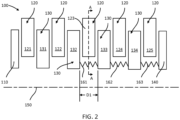
- FIG. 2 illustrates a portion of a multi-disk carbon and CMC brake system 20 from FIG. 1 prior to actuation of the multi-disk carbon and CMC brake system 20, in accordance with various embodiments, is depicted.
- the multi-disk carbon and CMC brake system 20 from FIG. 1 comprises a brake stack 100.
- the brake stack 100 comprises a pressure plate 110 at a proximal end of the brake stack 100 and an end plate 140 at a distal end of the brake stack 100.
- the brake stack 100 comprises a plurality of rotors 120 disposed between the pressure plate 110 and the end plate 140.
- the brake stack 100 further comprises a plurality of stators 130 interleaved between the plurality of rotors 120.
- the brake stack further comprises a centerline 150 about which the plurality of rotors 120 rotate.
- a centerline 150 about which the plurality of rotors 120 rotate.
- each rotor in the plurality of rotors 120 is separated from each stator in the plurality of stators by a gap.
- the gap is between 0.06 inches and 0.10 inches (0.15 cm - 0.26 cm), or between 0.065 inches and 0.095 inches (0.17 cm - 0.25 cm), or between 0.07 inches and 0.09 inches (18 cm - 0.23 cm).
- the plurality of rotors 120 comprises a first rotor 121 disposed proximate the pressure plate 110.
- the first rotor 121 is axially adjacent to the pressure plate 110.
- the plurality of stators 130 comprises a first stator 131 disposed proximate the first rotor 121.
- the first stator 131 is axially adjacent to the first rotor 121.
- the plurality of rotors 120 further comprises a second rotor 122, a third rotor 123, a fourth rotor 124, and a fifth rotor 125.
- the plurality of stators 130 further comprises a second stator 132, a third stator 133, and a fourth stator 134.
- a brake stack comprising five rotors and four stators, any number of rotors and stators is within the scope of this disclosure.
- the second rotor 122 is disposed axially adjacent to the first stator 131 and the second stator 132.
- the third rotor 123 is disposed axially adjacent to the second stator 132 and the third stator 133.
- the fourth rotor 124 is disposed axially adjacent to the third stator 133 and the fourth stator 134.
- the fifth rotor 125 is disposed axially adjacent to the fourth stator 134 and the end plate 140.
- each rotor in the plurality of rotors 120 is disposed along a radially outward from centerline 150 in relation to each stator in the plurality of stators 130.
- the pressure plate 110 and the end plate 140 are radially aligned with the plurality of stators 130.
- the brake stack 100 further comprises a first spring 161.
- the first spring 161 may be disposed between the second stator 132 and the third stator 133.
- the first spring 161 may be coupled to a circumferential portion of the second stator 132 proximate a radially inner end of the second stator 132 and a circumferential portion of the third stator 133 proximate a radially inner end of the third stator 133 by any method known in the art.
- the first spring 161 is a free component and installed in a compressed state or an uncompressed state.
- the first spring 161 is a wave spring, a coiled wave spring, a scrowave spring, or any other spring known in the art.
- the first spring 161 is made of stainless steel, such as A-286 stainless steel, 17-4 PH stainless steel, 15-5 PH stainless steel, or the like. In various embodiments, the first spring 161 is made of any high temperature metal known in the art, such as a nickel alloy, cobalt, or the like.
- the first spring 161 is installed in an uncompressed state at its free height.
- "free height,” as disclosed herein, is a spring distance between two components when the spring is in an uncompressed state.
- the first spring 161 may have a free height measured in the axial direction that is substantially equal to, or less than, a distance D1 between the second stator 132 and the third stator 133.
- a gap between a stator and an adjacent rotor is a function of the available brake running clearance.
- the running clearance may be a design choice based on the design intent of a multi-disk brake system.
- the brake stack 100 comprises a second spring 162.
- the second spring 162 may be disposed between the third stator 133 and the fourth stator 134.
- the second spring 162 may be coupled to a circumferential portion of the third stator 133 proximate a radially inner end of the third stator 133 and a circumferential portion of the fourth stator 134 proximate a radially inner end of the fourth stator 134.
- the second spring 162 may be the same type of spring or a different type of spring as the first spring 161. In various embodiments, the second spring 162 is the same type of spring as the first spring 161.
- the brake stack 100 comprises a third spring 163.
- the third spring 163 may be disposed between the fourth stator 134 and the end plate 140.
- the third spring 163 may be coupled to a circumferential portion of the fourth stator 134 proximate a radially inner end of the fourth stator 134 and a circumferential portion of the end plate 140 proximate a radially inner end of the end plate 140.
- the third spring 163 may be the same type of spring or a different type of spring as the first spring 161.
- the second spring 162 is the same type of spring as the first spring 161.
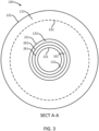
- the third rotor 123 comprises a radially inner end 221 and a radially outer end 222.
- the second stator 132 comprises a radially inner end 231 and a radially outer end 232.
- Radially outer end 232 of second stator 132 is illustrated as a hidden line in section A-A as it is hidden from view in section A-A because it is behind third rotor 123.
- first spring 161 comprises a radially inner end 261 and a radially outer end 262.
- first spring 161 is disposed between radially inner end 221 of third rotor 123 and radially inner end 231 of second stator 132.
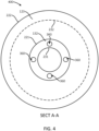
- the brake stack 400 comprises a plurality of springs 360 disposed circumferentially around second stator 132.
- each spring in the plurality of springs 360 is disposed between radially inner end 221 of the third rotor 123 and radially inner end 231 of the second stator 132.
- each spring in the plurality of springs 360 is a coil spring, or any other spring known in the art.
- a “first type of braking event,” as described herein, is braking to slow an aircraft during taxi, a non-emergency landing, or the like.
- a first type of braking event occurs at a braking pressure applied to the brake stack 100 that is less than a threshold brake pressure.
- a threshold brake pressure may be a design choice and vary based on design intent.
- a threshold brake pressure may be between 600 psi and 800 psi (4137 kPa - 5516 kPa), or 650 psi and 750 psi (4482 kPa - 5860 kPa), or between 675 psi and 725 psi (4654 kPa - 4999 kPa).
- the first spring 161 is partially compressed to a height of D2.
- D2 is less than D1.
- D2 is between 0.01 inches and 0.16 inches less than D1.
- pressure plate 110 is actuated axially toward end plate 140. An axial face of pressure plate 110 contacts a first axial face of first rotor 121, a second axial face of first rotor 121 contacts a first axial face of first stator 131, a second axial face of first stator 131 contacts a first axial face of second rotor 122, and a first axial face of second stator 132.
- a second axial face of second stator 132 is separated from a first axial face of third rotor 123 by a gap.
- a second axial face of third rotor 123 is separated from a first axial face of third stator 133 by a gap.
- second spring 162 and third spring 163 may be partially compressed as well during a first braking event. Due to the partial compression of second spring 162, a second axial face of third stator 133 is separated from a first axial face of fourth rotor 124 by a gap, and a second axial face of fourth rotor 124 is separated from a first axial face of fourth stator 134 by a gap. Similarly, due to the partial compression of third spring 163, a second axial face of fourth stator 134 is separated from a first axial face of fifth rotor 125 by a gap, and a second axial face of fifth rotor 125 is separated from a first axial face of end plate 140 by a gap.
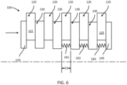
- a second type of braking event is braking during performance and emergency landings, service stops, or the like.
- a second type of braking event occurs at a braking pressure applied to the brake stack 100 that is greater than a threshold brake pressure.
- the threshold brake pressure may be between 600 psi and 800 psi (4137 kPa - 5516 kPa).
- an axial face of each rotor in the plurality of rotors 120 contacts an axial face of an adjacent stator in the plurality of stators 130. Additionally, an axial face of pressure plate 110 contacts an axial face of first rotor 121, and an axial face of fifth rotor 125 contacts an axial face of end plate 140.
- the first spring 161 is fully compress to a height of D3. In various embodiments, the height D3 is less than the height D2 from FIG. 5 during a first type braking event. In various embodiments, D3 is substantially equal to a width of a rotor in the plurality of rotors 120.
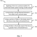
- the method comprises applying a force to a pressure plate of a multi-disk carbon and CMC brake system (step 702).
- the force is applied in the axial direction.
- the multi-disk carbon and CMC brake system may comprise a brake stack in accordance with FIGS. 1-6 .
- the method further comprises compressing a spring disposed between a first stator in a plurality of stators and a second stator in a plurality of stators (step 704).
- a plurality of rotors are interleaved between the plurality of stators, as depicted in FIGS. 1-6 .
- the method further comprises using a portion of disks in the brake stack if the force is less than a threshold force (step 706).
- a portion of disks may comprise at least one rotor and at least one stator.
- the threshold force corresponds to a threshold pressure.
- the threshold pressure is between 600 psi and 800 psi (4137 kPa - 5516 kPa), or 650 psi and 750 psi (4482 kPa - 5860 kPa), or between 675 psi and 725 psi (4654 kPa - 4999 kPa).
- the method further comprises using all disks in the brake stack if the force is greater than the threshold force (step 708). For example, each rotor in a plurality of rotors contacts an adjacent stator in a plurality of stators when the force is greater than the threshold force.
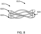
- first spring 161 comprises a wave spring 810.
- Wave spring 810 comprises a plurality of annular sheets 820.
- Each annular sheet in the plurality of annular sheets 820 has a sinusoidal shape along the circumference of the annular sheet.
- Each annular sheet in the plurality of annular sheets 820 is coupled to an adjacent annular sheet in the plurality of annular sheets 820 at a crest of the annular sheet and the adjacent annular sheet.
- any of the method or process descriptions may be executed in any order and are not necessarily limited to the order presented.
- any reference to singular includes plural embodiments, and any reference to more than one component or step may include a singular embodiment or step.
- Elements and steps in the figures are illustrated for simplicity and clarity and have not necessarily been rendered according to any particular sequence. For example, steps that may be performed concurrently or in different order are illustrated in the figures to help to improve understanding of embodiments of the present invention.
- Any reference to attached, fixed, connected or the like may include permanent, removable, temporary, partial, full and/or any other possible attachment option. Additionally, any reference to without contact (or similar phrases) may also include reduced contact or minimal contact. Surface shading lines may be used throughout the figures to denote different parts or areas but not necessarily to denote the same or different materials. In some cases, reference coordinates may be specific to each figure.
- references to "one embodiment,” “an embodiment,” “various embodiments,” etc. indicate that the embodiment described may include a particular feature, structure, or characteristic, but every embodiment may not necessarily include the particular feature, structure, or characteristic. Moreover, such phrases are not necessarily referring to the same embodiment. Further, when a particular feature, structure, or characteristic is described in connection with an embodiment, it is submitted that it may be within the knowledge of one skilled in the art to affect such feature, structure, or characteristic in connection with other embodiments whether or not explicitly described. After reading the description, it will be apparent to one skilled in the relevant art(s) how to implement the invention in alternative embodiments.
Landscapes
- Engineering & Computer Science (AREA)
- General Engineering & Computer Science (AREA)
- Mechanical Engineering (AREA)
- Aviation & Aerospace Engineering (AREA)
- Braking Arrangements (AREA)
Claims (7)
- Mehrscheibenbremssystem aus Kohlenstoff und Keramikmatrix-Verbundwerkstoff (CMC), Folgendes umfassend:
einen Bremsstapel (100), Folgendes umfassend:eine Druckplatte (110), die an einem proximalen Ende des Bremsstapels angeordnet ist;eine Endplatte (120), die distal zu der Druckplatte (110) angeordnet ist;eine Vielzahl von Rotoren (130), die zwischen der Druckplatte (110) und der Endplatte (140) angeordnet ist;eine Vielzahl von Statoren (130), die zwischen der Druckplatte (110) und der Endplatte (140) angeordnet ist, wobei die Vielzahl von Statoren (130) zwischen die Vielzahl von Rotoren (130) eingefügt ist;einen ersten Teil von Scheiben ohne Feder, einen zweiten Teil von Scheiben mit mindestens einer ersten Feder (161), die axial zwischen einem ersten Stator in der Vielzahl von Statoren (130) und einem benachbarten Stator in der Vielzahl von Statoren (130) angeordnet ist, wobei die erste Feder (161) radial einwärts von einem ersten Rotor in der Vielzahl von Rotoren (120) angeordnet ist, wobei die erste Feder (161) so konfiguriert ist, dass sie teilweise komprimiert wird, wenn auf die Druckplatte (140) eine Kraft ausgeübt wird, die geringer als eine Schwellenkraft ist;dadurch gekennzeichnet, dasseine erste axiale Statorfläche des ersten Stators von einer ersten axialen Rotorfläche des ersten Rotors getrennt wird, wenn die erste Feder (161) teilweise komprimiert wird. - Mehrscheibenbremssystem aus Kohlenstoff und CMC nach Anspruch 1, wobei die erste Feder (161) eine erste Wellenfeder ist.
- Mehrscheibenbremssystem aus Kohlenstoff und CMC nach Anspruch 1, wobei die Schwellenkraft einem Schwelleneffektivdruck entspricht, der einem Rollstopp oder einer Servicelandung eines Flugzeugs zugeordnet ist.
- Mehrscheibenbremssystem aus Kohlenstoff und CMC nach einem der vorhergehenden Ansprüche, wobei die erste Feder (161) so konfiguriert ist, dass sie vollständig komprimiert wird, wenn auf die Druckplatte (110) eine Kraft ausgeübt wird, die größer ist als eine Schwellenkraft, und wobei bevorzugt eine erste axiale Statorfläche des ersten Stators eine erste axiale Rotorfläche des ersten Rotors berührt, wenn die erste Feder (161) vollständig komprimiert ist.
- Mehrscheibenbremssystem aus Kohlenstoff und CMC nach Anspruch 2, ferner Folgendes umfassend:einen zweiten Rotor (122), der axial benachbart zu dem zweiten Stator angeordnet ist, wobei der zweite Rotor ein radial inneres Ende des zweiten Rotors aufweist;einen dritten Stator (133), der axial benachbart zu dem zweiten Rotor angeordnet ist; undeine zweite Feder (162), die axial zwischen dem zweiten Stator und dem dritten Stator und radial zwischen einem radial inneren Ende des zweiten Stators und dem radial inneren Ende des zweiten Rotors angeordnet ist.
- Mehrscheibenbremssystem aus Kohlenstoff und CMC nach Anspruch 5, wobei die zweite Feder (162) eine zweite Wellenfeder ist.
- Verfahren zur Verwendung eines Mehrscheibenbremssystems aus Kohlenstoff und Keramikmatrix-Verbundwerkstoff (CMC) nach Anspruch 1, wobei das Verfahren Folgendes umfasst:Ausüben einer Kraft auf die Druckplatte des Mehrscheibenbremssystems aus Kohlenstoff und CMC, umfassend den Bremsstapel;Komprimieren der Feder zwischen dem ersten Stator und dem zweiten Stator; undVerwenden des ersten Teils der Scheiben in dem Bremsstapel, wenn die Kraft kleiner als eine Schwellenkraft ist; undVerwenden aller Scheiben in dem Bremsstapel, wenn die Kraft größer als die Schwellenkraft ist.
Priority Applications (1)
| Application Number | Priority Date | Filing Date | Title |
|---|---|---|---|
| EP21210243.8A EP3978776B1 (de) | 2019-09-30 | 2019-12-13 | Kohlenstoffbremsstapelanordnung für verbesserte lebensdauer |
Applications Claiming Priority (1)
| Application Number | Priority Date | Filing Date | Title |
|---|---|---|---|
| US16/588,186 US11226019B2 (en) | 2019-09-30 | 2019-09-30 | Carbon brake stack assembly for improved life |
Related Child Applications (2)
| Application Number | Title | Priority Date | Filing Date |
|---|---|---|---|
| EP21210243.8A Division-Into EP3978776B1 (de) | 2019-09-30 | 2019-12-13 | Kohlenstoffbremsstapelanordnung für verbesserte lebensdauer |
| EP21210243.8A Division EP3978776B1 (de) | 2019-09-30 | 2019-12-13 | Kohlenstoffbremsstapelanordnung für verbesserte lebensdauer |
Publications (2)
| Publication Number | Publication Date |
|---|---|
| EP3798463A1 EP3798463A1 (de) | 2021-03-31 |
| EP3798463B1 true EP3798463B1 (de) | 2024-10-30 |
Family
ID=68916442
Family Applications (2)
| Application Number | Title | Priority Date | Filing Date |
|---|---|---|---|
| EP19216082.8A Active EP3798463B1 (de) | 2019-09-30 | 2019-12-13 | Kohlenstoffbremsstapelanordnung für verbesserte lebensdauer |
| EP21210243.8A Active EP3978776B1 (de) | 2019-09-30 | 2019-12-13 | Kohlenstoffbremsstapelanordnung für verbesserte lebensdauer |
Family Applications After (1)
| Application Number | Title | Priority Date | Filing Date |
|---|---|---|---|
| EP21210243.8A Active EP3978776B1 (de) | 2019-09-30 | 2019-12-13 | Kohlenstoffbremsstapelanordnung für verbesserte lebensdauer |
Country Status (2)
| Country | Link |
|---|---|
| US (1) | US11226019B2 (de) |
| EP (2) | EP3798463B1 (de) |
Citations (1)
| Publication number | Priority date | Publication date | Assignee | Title |
|---|---|---|---|---|
| JP2017116014A (ja) * | 2015-12-25 | 2017-06-29 | 曙ブレーキ工業株式会社 | ブレーキ装置 |
Family Cites Families (10)
| Publication number | Priority date | Publication date | Assignee | Title |
|---|---|---|---|---|
| US2518016A (en) * | 1946-07-16 | 1950-08-08 | Cardwell Mfg Company Inc | Cooled disk-type brake |
| US4207969A (en) | 1974-01-14 | 1980-06-17 | Robert Howell Industries | Wet disc friction device |
| US4279330A (en) | 1977-06-27 | 1981-07-21 | Walter Kidde & Company, Inc. | Double-acting disc brake |
| DE3467914D1 (en) | 1983-09-01 | 1988-01-14 | Eaton Corp | Spring engaged fluid released multi-disc brake assembly |
| US5603395A (en) * | 1992-03-05 | 1997-02-18 | Easom Engineering & Mfg. Corp. | Electrically actuated disc stack having low response time due to reduced residual magnetism for use in drives, brakes and combinations thereof |
| US20050276961A1 (en) | 2003-08-04 | 2005-12-15 | Sherwood Walter J | Materials and methods for making ceramic matrix composites |
| US8634971B2 (en) | 2009-05-05 | 2014-01-21 | Goodrich Corporation | Brake wear control system |
| US8662277B2 (en) | 2011-12-22 | 2014-03-04 | Fairfield Manufacturing Company, Inc. | Planetary gearbox with integral service brake |
| US9669810B2 (en) | 2012-01-10 | 2017-06-06 | Honeywell International Inc. | Brake assembly including independently activatable brake actuators |
| FR3021378B1 (fr) | 2014-05-21 | 2016-06-03 | Messier Bugatti Dowty | Frein a disques pour roue d'aeronef |
-
2019
- 2019-09-30 US US16/588,186 patent/US11226019B2/en active Active
- 2019-12-13 EP EP19216082.8A patent/EP3798463B1/de active Active
- 2019-12-13 EP EP21210243.8A patent/EP3978776B1/de active Active
Patent Citations (1)
| Publication number | Priority date | Publication date | Assignee | Title |
|---|---|---|---|---|
| JP2017116014A (ja) * | 2015-12-25 | 2017-06-29 | 曙ブレーキ工業株式会社 | ブレーキ装置 |
Also Published As
| Publication number | Publication date |
|---|---|
| US20210095728A1 (en) | 2021-04-01 |
| EP3978776A1 (de) | 2022-04-06 |
| EP3978776B1 (de) | 2025-08-13 |
| US11226019B2 (en) | 2022-01-18 |
| EP3798463A1 (de) | 2021-03-31 |
Similar Documents
| Publication | Publication Date | Title |
|---|---|---|
| US9541145B2 (en) | Keyed brake disk assembly | |
| US9194447B2 (en) | Keyed brake disk assembly | |
| US10968971B2 (en) | Multi-layer insulator for brake piston | |
| US10544844B2 (en) | Plate assemblies including floating wear linings for multi-disk brake systems and methods for reducing vibration in a multi-disk brake system | |
| EP3418601B1 (de) | Lamellenbremsanordnung mit hubbegrenzungsstift | |
| US12385537B2 (en) | Stator clip for brake assembly | |
| EP3798463B1 (de) | Kohlenstoffbremsstapelanordnung für verbesserte lebensdauer | |
| US20160304191A1 (en) | Increased brake radius to improve rto performance | |
| US10890227B2 (en) | Wear liner with unidirectional notch | |
| EP3404283A1 (de) | Torsionsrohr | |
| US11821478B2 (en) | Brake assembly with disks of variable thickness and methods for disk reuse | |
| US10948037B2 (en) | Segmented rivetless wear liner with structural carbon or ceramic core | |
| US20200300317A1 (en) | Segmented rivetless wear liner with structural carbon or ceramic core | |
| US11614136B2 (en) | Wear liner manufacturing systems and methods |
Legal Events
| Date | Code | Title | Description |
|---|---|---|---|
| PUAI | Public reference made under article 153(3) epc to a published international application that has entered the european phase |
Free format text: ORIGINAL CODE: 0009012 |
|
| STAA | Information on the status of an ep patent application or granted ep patent |
Free format text: STATUS: THE APPLICATION HAS BEEN PUBLISHED |
|
| AK | Designated contracting states |
Kind code of ref document: A1 Designated state(s): AL AT BE BG CH CY CZ DE DK EE ES FI FR GB GR HR HU IE IS IT LI LT LU LV MC MK MT NL NO PL PT RO RS SE SI SK SM TR |
|
| AX | Request for extension of the european patent |
Extension state: BA ME |
|
| STAA | Information on the status of an ep patent application or granted ep patent |
Free format text: STATUS: REQUEST FOR EXAMINATION WAS MADE |
|
| 17P | Request for examination filed |
Effective date: 20210916 |
|
| RBV | Designated contracting states (corrected) |
Designated state(s): AL AT BE BG CH CY CZ DE DK EE ES FI FR GB GR HR HU IE IS IT LI LT LU LV MC MK MT NL NO PL PT RO RS SE SI SK SM TR |
|
| STAA | Information on the status of an ep patent application or granted ep patent |
Free format text: STATUS: EXAMINATION IS IN PROGRESS |
|
| 17Q | First examination report despatched |
Effective date: 20220217 |
|
| P01 | Opt-out of the competence of the unified patent court (upc) registered |
Effective date: 20230922 |
|
| GRAP | Despatch of communication of intention to grant a patent |
Free format text: ORIGINAL CODE: EPIDOSNIGR1 |
|
| STAA | Information on the status of an ep patent application or granted ep patent |
Free format text: STATUS: GRANT OF PATENT IS INTENDED |
|
| INTG | Intention to grant announced |
Effective date: 20240612 |
|
| GRAS | Grant fee paid |
Free format text: ORIGINAL CODE: EPIDOSNIGR3 |
|
| GRAA | (expected) grant |
Free format text: ORIGINAL CODE: 0009210 |
|
| STAA | Information on the status of an ep patent application or granted ep patent |
Free format text: STATUS: THE PATENT HAS BEEN GRANTED |
|
| AK | Designated contracting states |
Kind code of ref document: B1 Designated state(s): AL AT BE BG CH CY CZ DE DK EE ES FI FR GB GR HR HU IE IS IT LI LT LU LV MC MK MT NL NO PL PT RO RS SE SI SK SM TR |
|
| REG | Reference to a national code |
Ref country code: GB Ref legal event code: FG4D |
|
| REG | Reference to a national code |
Ref country code: CH Ref legal event code: EP |
|
| REG | Reference to a national code |
Ref country code: IE Ref legal event code: FG4D |
|
| REG | Reference to a national code |
Ref country code: DE Ref legal event code: R096 Ref document number: 602019061065 Country of ref document: DE |
|
| REG | Reference to a national code |
Ref country code: LT Ref legal event code: MG9D |
|
| REG | Reference to a national code |
Ref country code: NL Ref legal event code: MP Effective date: 20241030 |
|
| PG25 | Lapsed in a contracting state [announced via postgrant information from national office to epo] |
Ref country code: HR Free format text: LAPSE BECAUSE OF FAILURE TO SUBMIT A TRANSLATION OF THE DESCRIPTION OR TO PAY THE FEE WITHIN THE PRESCRIBED TIME-LIMIT Effective date: 20241030 Ref country code: PT Free format text: LAPSE BECAUSE OF FAILURE TO SUBMIT A TRANSLATION OF THE DESCRIPTION OR TO PAY THE FEE WITHIN THE PRESCRIBED TIME-LIMIT Effective date: 20250228 Ref country code: IS Free format text: LAPSE BECAUSE OF FAILURE TO SUBMIT A TRANSLATION OF THE DESCRIPTION OR TO PAY THE FEE WITHIN THE PRESCRIBED TIME-LIMIT Effective date: 20250228 |
|
| PG25 | Lapsed in a contracting state [announced via postgrant information from national office to epo] |
Ref country code: FI Free format text: LAPSE BECAUSE OF FAILURE TO SUBMIT A TRANSLATION OF THE DESCRIPTION OR TO PAY THE FEE WITHIN THE PRESCRIBED TIME-LIMIT Effective date: 20241030 Ref country code: NL Free format text: LAPSE BECAUSE OF FAILURE TO SUBMIT A TRANSLATION OF THE DESCRIPTION OR TO PAY THE FEE WITHIN THE PRESCRIBED TIME-LIMIT Effective date: 20241030 |
|
| REG | Reference to a national code |
Ref country code: AT Ref legal event code: MK05 Ref document number: 1737136 Country of ref document: AT Kind code of ref document: T Effective date: 20241030 |
|
| PG25 | Lapsed in a contracting state [announced via postgrant information from national office to epo] |
Ref country code: BG Free format text: LAPSE BECAUSE OF FAILURE TO SUBMIT A TRANSLATION OF THE DESCRIPTION OR TO PAY THE FEE WITHIN THE PRESCRIBED TIME-LIMIT Effective date: 20241030 |
|
| PG25 | Lapsed in a contracting state [announced via postgrant information from national office to epo] |
Ref country code: ES Free format text: LAPSE BECAUSE OF FAILURE TO SUBMIT A TRANSLATION OF THE DESCRIPTION OR TO PAY THE FEE WITHIN THE PRESCRIBED TIME-LIMIT Effective date: 20241030 |
|
| PG25 | Lapsed in a contracting state [announced via postgrant information from national office to epo] |
Ref country code: NO Free format text: LAPSE BECAUSE OF FAILURE TO SUBMIT A TRANSLATION OF THE DESCRIPTION OR TO PAY THE FEE WITHIN THE PRESCRIBED TIME-LIMIT Effective date: 20250130 |
|
| PG25 | Lapsed in a contracting state [announced via postgrant information from national office to epo] |
Ref country code: AT Free format text: LAPSE BECAUSE OF FAILURE TO SUBMIT A TRANSLATION OF THE DESCRIPTION OR TO PAY THE FEE WITHIN THE PRESCRIBED TIME-LIMIT Effective date: 20241030 Ref country code: GR Free format text: LAPSE BECAUSE OF FAILURE TO SUBMIT A TRANSLATION OF THE DESCRIPTION OR TO PAY THE FEE WITHIN THE PRESCRIBED TIME-LIMIT Effective date: 20250131 Ref country code: LV Free format text: LAPSE BECAUSE OF FAILURE TO SUBMIT A TRANSLATION OF THE DESCRIPTION OR TO PAY THE FEE WITHIN THE PRESCRIBED TIME-LIMIT Effective date: 20241030 |
|
| PG25 | Lapsed in a contracting state [announced via postgrant information from national office to epo] |
Ref country code: PL Free format text: LAPSE BECAUSE OF FAILURE TO SUBMIT A TRANSLATION OF THE DESCRIPTION OR TO PAY THE FEE WITHIN THE PRESCRIBED TIME-LIMIT Effective date: 20241030 |
|
| PG25 | Lapsed in a contracting state [announced via postgrant information from national office to epo] |
Ref country code: RS Free format text: LAPSE BECAUSE OF FAILURE TO SUBMIT A TRANSLATION OF THE DESCRIPTION OR TO PAY THE FEE WITHIN THE PRESCRIBED TIME-LIMIT Effective date: 20250130 |
|
| REG | Reference to a national code |
Ref country code: DE Ref legal event code: R119 Ref document number: 602019061065 Country of ref document: DE |
|
| PG25 | Lapsed in a contracting state [announced via postgrant information from national office to epo] |
Ref country code: SM Free format text: LAPSE BECAUSE OF FAILURE TO SUBMIT A TRANSLATION OF THE DESCRIPTION OR TO PAY THE FEE WITHIN THE PRESCRIBED TIME-LIMIT Effective date: 20241030 |
|
| PG25 | Lapsed in a contracting state [announced via postgrant information from national office to epo] |
Ref country code: MC Free format text: LAPSE BECAUSE OF FAILURE TO SUBMIT A TRANSLATION OF THE DESCRIPTION OR TO PAY THE FEE WITHIN THE PRESCRIBED TIME-LIMIT Effective date: 20241030 |
|
| PG25 | Lapsed in a contracting state [announced via postgrant information from national office to epo] |
Ref country code: DK Free format text: LAPSE BECAUSE OF FAILURE TO SUBMIT A TRANSLATION OF THE DESCRIPTION OR TO PAY THE FEE WITHIN THE PRESCRIBED TIME-LIMIT Effective date: 20241030 |
|
| PG25 | Lapsed in a contracting state [announced via postgrant information from national office to epo] |
Ref country code: EE Free format text: LAPSE BECAUSE OF FAILURE TO SUBMIT A TRANSLATION OF THE DESCRIPTION OR TO PAY THE FEE WITHIN THE PRESCRIBED TIME-LIMIT Effective date: 20241030 |
|
| PG25 | Lapsed in a contracting state [announced via postgrant information from national office to epo] |
Ref country code: RO Free format text: LAPSE BECAUSE OF FAILURE TO SUBMIT A TRANSLATION OF THE DESCRIPTION OR TO PAY THE FEE WITHIN THE PRESCRIBED TIME-LIMIT Effective date: 20241030 |
|
| PG25 | Lapsed in a contracting state [announced via postgrant information from national office to epo] |
Ref country code: SK Free format text: LAPSE BECAUSE OF FAILURE TO SUBMIT A TRANSLATION OF THE DESCRIPTION OR TO PAY THE FEE WITHIN THE PRESCRIBED TIME-LIMIT Effective date: 20241030 |
|
| PG25 | Lapsed in a contracting state [announced via postgrant information from national office to epo] |
Ref country code: CZ Free format text: LAPSE BECAUSE OF FAILURE TO SUBMIT A TRANSLATION OF THE DESCRIPTION OR TO PAY THE FEE WITHIN THE PRESCRIBED TIME-LIMIT Effective date: 20241030 |
|
| PG25 | Lapsed in a contracting state [announced via postgrant information from national office to epo] |
Ref country code: IT Free format text: LAPSE BECAUSE OF FAILURE TO SUBMIT A TRANSLATION OF THE DESCRIPTION OR TO PAY THE FEE WITHIN THE PRESCRIBED TIME-LIMIT Effective date: 20241030 |
|
| REG | Reference to a national code |
Ref country code: CH Ref legal event code: PL |
|
| PG25 | Lapsed in a contracting state [announced via postgrant information from national office to epo] |
Ref country code: LU Free format text: LAPSE BECAUSE OF NON-PAYMENT OF DUE FEES Effective date: 20241213 |
|
| PLBE | No opposition filed within time limit |
Free format text: ORIGINAL CODE: 0009261 |
|
| STAA | Information on the status of an ep patent application or granted ep patent |
Free format text: STATUS: NO OPPOSITION FILED WITHIN TIME LIMIT |
|
| PG25 | Lapsed in a contracting state [announced via postgrant information from national office to epo] |
Ref country code: SE Free format text: LAPSE BECAUSE OF FAILURE TO SUBMIT A TRANSLATION OF THE DESCRIPTION OR TO PAY THE FEE WITHIN THE PRESCRIBED TIME-LIMIT Effective date: 20241030 |
|
| 26N | No opposition filed |
Effective date: 20250731 |
|
| REG | Reference to a national code |
Ref country code: BE Ref legal event code: MM Effective date: 20241231 |
|
| PG25 | Lapsed in a contracting state [announced via postgrant information from national office to epo] |
Ref country code: DE Free format text: LAPSE BECAUSE OF NON-PAYMENT OF DUE FEES Effective date: 20250701 |
|
| PG25 | Lapsed in a contracting state [announced via postgrant information from national office to epo] |
Ref country code: BE Free format text: LAPSE BECAUSE OF NON-PAYMENT OF DUE FEES Effective date: 20241231 |
|
| PG25 | Lapsed in a contracting state [announced via postgrant information from national office to epo] |
Ref country code: CH Free format text: LAPSE BECAUSE OF NON-PAYMENT OF DUE FEES Effective date: 20241231 |
|
| PG25 | Lapsed in a contracting state [announced via postgrant information from national office to epo] |
Ref country code: IE Free format text: LAPSE BECAUSE OF NON-PAYMENT OF DUE FEES Effective date: 20241213 |
|
| PGFP | Annual fee paid to national office [announced via postgrant information from national office to epo] |
Ref country code: GB Payment date: 20251119 Year of fee payment: 7 |
|
| PGFP | Annual fee paid to national office [announced via postgrant information from national office to epo] |
Ref country code: FR Payment date: 20251120 Year of fee payment: 7 |