EP4166804A1 - Dämpfer - Google Patents
Dämpfer Download PDFInfo
- Publication number
- EP4166804A1 EP4166804A1 EP21826714.4A EP21826714A EP4166804A1 EP 4166804 A1 EP4166804 A1 EP 4166804A1 EP 21826714 A EP21826714 A EP 21826714A EP 4166804 A1 EP4166804 A1 EP 4166804A1
- Authority
- EP
- European Patent Office
- Prior art keywords
- slits
- damper
- slit
- outer ring
- viscous fluid
- Prior art date
- Legal status (The legal status is an assumption and is not a legal conclusion. Google has not performed a legal analysis and makes no representation as to the accuracy of the status listed.)
- Pending
Links
Images


Classifications
-
- F—MECHANICAL ENGINEERING; LIGHTING; HEATING; WEAPONS; BLASTING
- F16—ENGINEERING ELEMENTS AND UNITS; GENERAL MEASURES FOR PRODUCING AND MAINTAINING EFFECTIVE FUNCTIONING OF MACHINES OR INSTALLATIONS; THERMAL INSULATION IN GENERAL
- F16F—SPRINGS; SHOCK-ABSORBERS; MEANS FOR DAMPING VIBRATION
- F16F9/00—Springs, vibration-dampers, shock-absorbers, or similarly-constructed movement-dampers using a fluid or the equivalent as damping medium
- F16F9/10—Springs, vibration-dampers, shock-absorbers, or similarly-constructed movement-dampers using a fluid or the equivalent as damping medium using liquid only; using a fluid of which the nature is immaterial
- F16F9/12—Devices with one or more rotary vanes turning in the fluid any throttling effect being immaterial, i.e. damping by viscous shear effect only
-
- F—MECHANICAL ENGINEERING; LIGHTING; HEATING; WEAPONS; BLASTING
- F01—MACHINES OR ENGINES IN GENERAL; ENGINE PLANTS IN GENERAL; STEAM ENGINES
- F01D—NON-POSITIVE DISPLACEMENT MACHINES OR ENGINES, e.g. STEAM TURBINES
- F01D25/00—Component parts, details, or accessories, not provided for in, or of interest apart from, other groups
- F01D25/16—Arrangement of bearings; Supporting or mounting bearings in casings
- F01D25/162—Bearing supports
- F01D25/164—Flexible supports; Vibration damping means associated with the bearing
-
- F—MECHANICAL ENGINEERING; LIGHTING; HEATING; WEAPONS; BLASTING
- F16—ENGINEERING ELEMENTS AND UNITS; GENERAL MEASURES FOR PRODUCING AND MAINTAINING EFFECTIVE FUNCTIONING OF MACHINES OR INSTALLATIONS; THERMAL INSULATION IN GENERAL
- F16C—SHAFTS; FLEXIBLE SHAFTS; ELEMENTS OR CRANKSHAFT MECHANISMS; ROTARY BODIES OTHER THAN GEARING ELEMENTS; BEARINGS
- F16C27/00—Elastic or yielding bearings or bearing supports, for exclusively rotary movement
- F16C27/04—Ball or roller bearings, e.g. with resilient rolling bodies
- F16C27/045—Ball or roller bearings, e.g. with resilient rolling bodies with a fluid film, e.g. squeeze film damping
-
- F—MECHANICAL ENGINEERING; LIGHTING; HEATING; WEAPONS; BLASTING
- F16—ENGINEERING ELEMENTS AND UNITS; GENERAL MEASURES FOR PRODUCING AND MAINTAINING EFFECTIVE FUNCTIONING OF MACHINES OR INSTALLATIONS; THERMAL INSULATION IN GENERAL
- F16C—SHAFTS; FLEXIBLE SHAFTS; ELEMENTS OR CRANKSHAFT MECHANISMS; ROTARY BODIES OTHER THAN GEARING ELEMENTS; BEARINGS
- F16C35/00—Rigid support of bearing units; Housings, e.g. caps, covers
- F16C35/04—Rigid support of bearing units; Housings, e.g. caps, covers in the case of ball or roller bearings
- F16C35/06—Mounting or dismounting of ball or roller bearings; Fixing them onto shaft or in housing
- F16C35/07—Fixing them on the shaft or housing with interposition of an element
- F16C35/077—Fixing them on the shaft or housing with interposition of an element between housing and outer race ring
-
- F—MECHANICAL ENGINEERING; LIGHTING; HEATING; WEAPONS; BLASTING
- F16—ENGINEERING ELEMENTS AND UNITS; GENERAL MEASURES FOR PRODUCING AND MAINTAINING EFFECTIVE FUNCTIONING OF MACHINES OR INSTALLATIONS; THERMAL INSULATION IN GENERAL
- F16F—SPRINGS; SHOCK-ABSORBERS; MEANS FOR DAMPING VIBRATION
- F16F15/00—Suppression of vibrations in systems; Means or arrangements for avoiding or reducing out-of-balance forces, e.g. due to motion
- F16F15/02—Suppression of vibrations of non-rotating, e.g. reciprocating systems; Suppression of vibrations of rotating systems by use of members not moving with the rotating systems
- F16F15/023—Suppression of vibrations of non-rotating, e.g. reciprocating systems; Suppression of vibrations of rotating systems by use of members not moving with the rotating systems using fluid means
- F16F15/0237—Suppression of vibrations of non-rotating, e.g. reciprocating systems; Suppression of vibrations of rotating systems by use of members not moving with the rotating systems using fluid means involving squeeze-film damping
-
- F—MECHANICAL ENGINEERING; LIGHTING; HEATING; WEAPONS; BLASTING
- F16—ENGINEERING ELEMENTS AND UNITS; GENERAL MEASURES FOR PRODUCING AND MAINTAINING EFFECTIVE FUNCTIONING OF MACHINES OR INSTALLATIONS; THERMAL INSULATION IN GENERAL
- F16C—SHAFTS; FLEXIBLE SHAFTS; ELEMENTS OR CRANKSHAFT MECHANISMS; ROTARY BODIES OTHER THAN GEARING ELEMENTS; BEARINGS
- F16C19/00—Bearings with rolling contact, for exclusively rotary movement
- F16C19/02—Bearings with rolling contact, for exclusively rotary movement with bearing balls essentially of the same size in one or more circular rows
- F16C19/04—Bearings with rolling contact, for exclusively rotary movement with bearing balls essentially of the same size in one or more circular rows for radial load mainly
- F16C19/06—Bearings with rolling contact, for exclusively rotary movement with bearing balls essentially of the same size in one or more circular rows for radial load mainly with a single row or balls
-
- F—MECHANICAL ENGINEERING; LIGHTING; HEATING; WEAPONS; BLASTING
- F16—ENGINEERING ELEMENTS AND UNITS; GENERAL MEASURES FOR PRODUCING AND MAINTAINING EFFECTIVE FUNCTIONING OF MACHINES OR INSTALLATIONS; THERMAL INSULATION IN GENERAL
- F16C—SHAFTS; FLEXIBLE SHAFTS; ELEMENTS OR CRANKSHAFT MECHANISMS; ROTARY BODIES OTHER THAN GEARING ELEMENTS; BEARINGS
- F16C2360/00—Engines or pumps
-
- F—MECHANICAL ENGINEERING; LIGHTING; HEATING; WEAPONS; BLASTING
- F16—ENGINEERING ELEMENTS AND UNITS; GENERAL MEASURES FOR PRODUCING AND MAINTAINING EFFECTIVE FUNCTIONING OF MACHINES OR INSTALLATIONS; THERMAL INSULATION IN GENERAL
- F16C—SHAFTS; FLEXIBLE SHAFTS; ELEMENTS OR CRANKSHAFT MECHANISMS; ROTARY BODIES OTHER THAN GEARING ELEMENTS; BEARINGS
- F16C33/00—Parts of bearings; Special methods for making bearings or parts thereof
- F16C33/72—Sealings
Definitions
- the present disclosure relates to the structure of a damper that is, in various rotating machines such as a jet engine, a turbo compressor, and a turbocharger, located between a rotating shaft and a support, the damper serving to damp vibration that is transmitted from the rotating shaft to the support.
- a squeeze film damper (or a squeeze film damper bearing) is used between a rotating shaft and a support in order to damp vibration that is transmitted from the rotating shaft to the support.
- the squeeze film damper forms a viscous fluid film between the rotating shaft (or bearing) and a fixing surface that supports the rotating shaft (or bearing). Vibration of the rotating shaft is damped by flowing movement and compression of the viscous fluid.
- Patent Literatures 1 and 2 each disclose this type of squeeze film damper.
- Patent Literature 1 discloses a bearing damper element.
- the bearing damper element is located between a rotating shaft and a support, and includes a cylindrical body fixed to the support. There is a slit between the inner surface and the outer surface of the cylindrical body. The slit is machined by wire-cut electrical discharge machining or laser machining. The slit is filled with a viscous fluid.
- Patent Literature 2 discloses a squeeze film damper bearing.
- the squeeze film damper bearing includes: a hollow cylindrical inner ring that supports a rotating shaft or a bearing; a hollow cylindrical outer ring that is in close contact with, and fixed to, the bearing or a fixing surface; and three or more middle arc portions located at regular intervals in a circumferential direction between the inner ring and the outer ring, the middle arc portions being separated from each other by slits.
- One end of each middle arc portion in the circumferential direction is integrally coupled to the outer ring, and the other end of each middle arc portion in the circumferential direction is integrally coupled to the inner ring.
- the vibration damping effect can be increased.
- the reduction in the slit width causes disadvantages, such as the following.
- the damping characteristics of the damper become more susceptible to static eccentricity and vibration amplitude of the rotating shaft.
- the machining current needs to be reduced. Consequently, the machining time is prolonged, which causes an increase in manufacturing cost.
- An object of the present disclosure is to propose a structure of a damper, the structure making it possible to, in the damper, increase the slit width of a slit (the slit is a gap in which a viscous fluid film is formed by a viscous fluid) compared to conventional art while maintaining or improving vibration damping characteristics.
- a damper includes: a damper body that is cylindrical, the damper body including an inner ring and an outer ring that are concentrically located, arc springs that are located side by side in a circumferential direction between the inner ring and the outer ring, and slits that separate the inner ring, the outer ring, and the arc springs from each other; sealers located on both sides of the damper body in an axial direction, respectively, the sealers including sealing surfaces, respectively, the sealing surfaces facing open ends of the slits in the axial direction, with gaps present between the sealing surfaces and the open ends of the slits; and a viscous fluid that fills the slits and the gaps.
- the arc springs include a first arc spring and a second arc spring that are located side by side in the circumferential direction.
- Each of the slits includes: an inner slit portion that separates the first arc spring and the inner ring from each other; an outer slit portion that separates the second arc spring and the outer ring from each other; and a connecting portion that connects the inner slit portion and the outer slit portion.
- the connecting portion includes a restrictor that restricts movement of the viscous fluid between the inner slit portion and the outer slit portion.
- the damper configured as above includes a fluid film that is continuous in the slits and the gaps (the gaps are hereinafter referred to as "end seal gaps").
- the gaps are hereinafter referred to as "end seal gaps"
- vibration damping squeeze damping
- viscous resistance occurs in the fluid film in the end seal gaps. Consequently, vibration damping by energy dissipation (so-called dashpot damping) occurs.
- the movement of the viscous fluid from the inner slit portion to the outer slit portion (or from the outer slit portion to the inner slit portion) is restricted by the restrictor of the connecting portion of each slit. Accordingly, the viscous fluid in the slits is led to the end seal gaps due to the vibration of the rotating shaft. This makes it possible to cause vibration damping effectively.
- the slit width of the slits can be increased compared to the slit width in conventional dampers while maintaining or improving vibration damping characteristics compared to conventional dampers.
- a damper includes: a damper body that is cylindrical, the damper body including an inner ring and an outer ring that are concentrically located, arc springs that are located side by side in a circumferential direction between the inner ring and the outer ring, and slits that separate the inner ring, the outer ring, and the arc springs from each other; sealers located on both sides of the damper body in an axial direction, respectively, the sealers including sealing surfaces, respectively, the sealing surfaces facing open ends of the slits in the axial direction, with gaps present between the sealing surfaces and the open ends of the slits; and a viscous fluid that fills the slits and the gaps.
- the damper body includes at least one fluid feeding hole that extends in a radial direction from an outer surface of the outer ring, communicates with at least one of the slits, and feeds the viscous fluid to the at least one of the slits.
- the fluid feeding hole includes a reverse flow preventer that prevents a reverse low of the viscous fluid from the at least one of the slits to the fluid feeding hole.
- the damper configured as above includes a fluid film that is continuous in the slits and the gaps (the gaps are hereinafter referred to as "end seal gaps").
- the gaps are hereinafter referred to as "end seal gaps"
- vibration damping squeeze damping
- viscous resistance occurs in the fluid film in the end seal gaps. Consequently, vibration damping by energy dissipation (so-called dashpot damping) occurs.
- the slit width of the slits can be increased compared to the slit width in conventional dampers while maintaining or improving vibration damping characteristics compared to conventional dampers.
- the slit width of the slits in the damper can be increased compared to the slit width in conventional dampers while maintaining or improving vibration damping characteristics compared to conventional dampers.
- FIG. 1 is a sectional side view of a rotating shaft support 10 of a rotating machine 1 including a damper 2 according to the present embodiment.
- the damper 2 according to the present disclosure is applicable to, for example, any of various rotating machines, such as a jet engine, a turbo compressor, or a turbocharger.
- the rotating machine 1 shown in FIG. 1 includes: a rotating shaft 11; a housing 12, which serves as a support for the rotating shaft 11; and a bearing 13.
- the rotating shaft 11 is rotatably supported on the housing 12 by the bearing 13, which is located between the rotating shaft 11 and the housing 12.
- the bearing 13 may be either a rolling bearing or a plain bearing.
- the rotating machine 1 further includes the damper 2.
- the damper 2 has a function of centering the rotating shaft 11 as well as a function of damping the vibration of the rotating shaft 11.
- the damper 2 is located between the outer periphery of the bearing 13 and the inner periphery of the housing 12.
- the damper 2 may be located between the outer periphery of the rotating shaft 11 and the inner periphery of the bearing 13.
- the bearing 13 is a rolling bearing including an inner ring, an outer ring, and a rolling element
- the damper 2 may be configured as a part of the outer ring, or a part of the inner ring, of the bearing 13.
- the damper 2 may be configured as a part of the bearing 13.
- the damper 2 includes a damper body 20, sealers 30, and a viscous fluid 5.
- the damper body 20 has a hollow cylindrical shape.
- the rotational axis of the damper body 20 as a solid figure (a solid of revolution) is referred to as "the damper axis A";
- the axial direction X of the damper axis A is parallel to the axial direction of the rotating shaft 11;
- the radial direction of a circle whose center is the damper axis A is referred to as "the radial direction”;
- the circumferential direction of the circle whose center is the damper axis A is referred to as "the circumferential direction”.
- the outer surface of the damper body 20 is in close contact with, and fixed to, a cylindrical support 12a of the housing 12.
- the damper body 20 does not rotate together with the rotating shaft 11, and allows the rotating shaft 11 to rotate about its center axis at a predetermined high speed.
- the damper body 20 includes an inner ring 21, an outer ring 22, and four arc springs 23.
- the inner ring 21 and the outer ring 22 each have a hollow cylindrical shape.
- the outer ring 22 and the inner ring 21 are concentrically located about the damper axis A, such that the outer periphery of the inner ring 21 and the inner periphery of the outer ring 22 are spaced apart from each other in the radial direction.
- FIG. 2 shows the damper body 20 as seen in the axial direction X.
- the four arc springs 23 are located between the inner ring 21 and the outer ring 22, which are spaced apart from each other in the radial direction.
- the four arc springs 23 are located side by side in the circumferential direction at substantially regular intervals.
- Each arc spring 23 is an arc-shaped component.
- the inner surface and the outer surface of the arc spring 23 are each an arc surface whose center is the damper axis A.
- the inner ring 21, the outer ring 22, and the arc springs 23 are, as a whole, a single component although the inner ring 21, the outer ring 22, and the arc springs 23 are partly separated from each other by the four slits 4.
- the inner surfaces of the arc springs 23 face the outer surface of the inner ring 21, with the slits 4 located between the outer surface of the inner ring 21 and the inner surfaces of the arc springs 23.
- the outer surfaces of the arc springs 23 face the inner surface of the outer ring 22, with the slits 4 located between the inner surface of the outer ring 22 and the outer surfaces of the arc springs 23.
- Each arc spring 23 includes a first end 23a and a second end 23b.
- the first end 23a is one end of the arc spring 23 in the circumferential direction
- the second end 23b is the other end of the arc spring 23 in the circumferential direction.
- the first end 23a of each arc spring 23 is connected to the inner ring 21.
- the second end 23b of each arc spring 23 is connected to the outer ring 22.
- Each slit 4 includes a first end hole 41, an inner slit portion 42, a connecting portion 43, an outer slit portion 44, and a second end hole 45, which are continuous in this order.
- the slits 4 penetrate the damper body 20 in the axial direction X.
- the second end hole 45 is positioned toward the outer peripheral side relative to the first end hole 41.
- the first end hole 41 and the second end hole 45 serve to reduce stress that occurs in the damper body 20.
- the first end hole 41 and the second end hole 45 are holes that first receive a wire therein at the time of machining the slit 4 in a cylindrical raw material of the damper body 20 by wire-cut electrical discharge machining.
- the inner slit portion 42 is arc-shaped such that it extends in the circumferential direction from the first end hole 41.
- the outer slit portion 44 is arc-shaped such that it extends in the circumferential direction from the inner slit portion 42.
- first arc spring those that are adjacent to each other in the circumferential direction
- second arc spring the inner slit portion 42 of one slit 4 separates the first arc spring and the inner ring 21 from each other
- the outer slit portion 44 of the one slit 4 separates the second arc spring and the outer ring 22 from each other.
- the inner slit portion 42 and the outer slit portion 44 of each slit 4 are shifted from each other in the circumferential direction, and also shifted from each other in the radial direction.
- the connecting portion 43 connects the inner slit portion 42 and the outer slit portion 44 in the circumferential direction.
- the direction in which the connecting portion 43 extends includes a radial direction component and a circumferential direction component.
- Each slit 4 is a "squeeze gap G1".
- a fluid film (a squeeze film) is formed by the viscous fluid 5, which fills the slit 4.
- the viscous fluid 5 is not particularly limited, but may be lubricating oil, for example.
- Each fluid feeding hole 27 extends in the radial direction. In the present embodiment, on the outer surface of the damper body 20, four fluid feeding holes 27 are located at regular intervals in the circumferential direction. Each fluid feeding hole 27 communicates with at least one slit 4. In the present embodiment, each fluid feeding hole 27 passes through the inner slit portion 42 of the slit 4 that is one of two slits 4 adjacent to each other in the circumferential direction, and passes through the outer slit portion 44 of the other one of the two slits 4. Each fluid feeding hole 27 communicates with a fluid feeding passage 12b in the support 12a of the housing 12. The viscous fluid 5 fed through the fluid feeding passage 12b is fed to the slits 4 through the fluid feeding hole 27.
- the slits 4 have a slit width C (i.e., the dimension of each slit 4 in the radial direction), which is set so that the slit width C will not become 0 due to axial vibration of the rotating shaft 11, i.e., so that the inner ring 21, the outer ring 22, and the arc springs 23 will not come into contact with each other.
- a slit width C i.e., the dimension of each slit 4 in the radial direction
- FIG. 3 is a sectional side view of the damper body 20, the view illustrating the slit width C.
- the diameter of a circle that passes between the inner peripheral edge and the outer peripheral edge of each arc spring 23 at the middle between the inner peripheral edge and the outer peripheral edge in the radial direction is an "arc spring center diameter D".
- the ratio of the slit width C (i.e., the dimension of each slit 4 in the radial direction) of at least one part of each slit 4 to the arc spring center diameter D (C / D) is not less than 1 / 100.
- the slit width C of the damper 2 of the present disclosure is not limited to this example.
- the sealers 30 are located on both sides of the damper body 20 in the axial direction X, respectively.
- Each sealer 30 is in the shape of a hollow discoid plate.
- the sealers 30 include sealing surfaces 31, respectively.
- the sealing surfaces 31 face open ends of the slits 4 in the axial direction X, with minute gaps (hereinafter, "end seal gaps G2") present between the sealing surfaces 31 and the open ends of the slits 4. That is, the end seal gaps G2 are located between the sealing surfaces 31 of the sealers 30 and the end surfaces of the damper body 20 in the axial direction X.
- Each slit 4 of the damper body 20 communicates with the end seal gaps G2.
- the end seal gaps G2 are filled with the viscous fluid 5.
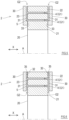
- FIGS. 4 to 7 is a sectional view of a part of the damper 2, the sectional view illustrating a configuration example of the end seal gaps G2.
- coupling surfaces 32 which are located on the outer side of the respective sealers 30, are coupled to the outer ring 22 of the damper body 20.
- the sealing surfaces 31 are located on portions of the respective sealers 30, the portions facing the inner ring 21, the arc springs 23, and the slits 4 of the damper body 20.
- the sealing surfaces 31 are recessed, relative to the coupling surfaces 32, away from the damper body 20 in the axial direction X. In this manner, surfaces of the respective sealers 30, the surfaces facing the damper body 20, are stepped, and these steps surfaces form the end seal gaps G2.
- coupling surfaces 33 which are located on the inner side of the respective sealers 30, are coupled to the inner ring 21 of the damper body 20.
- Portions of the respective sealers 30, the portions facing the outer ring 22, the arc springs 23, and the slits 4 of the damper body 20, serve as sealing surfaces 31, which are recessed, relative to the coupling surfaces 33, away from the damper body 20 in the axial direction X.
- surfaces of the respective sealers 30, the surfaces facing the damper body 20 are stepped, and these stepped surfaces form the end seal gaps G2.
- coupling surfaces 32 which are located on the outer side of the respective sealers 30, are coupled to the outer ring 22 of the damper body 20 via thin plates 35, respectively.
- the sealers 30 and the damper body 20 are spaced apart from each other by the thin plates 35, thereby achieving the formation of the end seal gaps G2.
- the thickness of each thin plate 35 is the gap dimension of each end seal gap G2.
- the sealing surfaces 31 face the inner ring 21, the arc springs 23, and the slits 4 of the damper body 20 in the axial direction X, with the end seal gaps G2 present between the sealing surfaces 31 and the inner ring 21, the arc springs 23, and the slits 4 of the damper body 20.
- coupling surfaces 33 which are located on the inner side of the respective sealers 30, are coupled to the inner ring 21 of the damper body 20 via thin plates 36, respectively.
- the sealers 30 and the damper body 20 are spaced apart from each other by the thin plates 36, thereby achieving the formation of the end seal gaps G2.
- the thickness of each thin plate 36 is the gap dimension of each end seal gap G2.
- the sealing surfaces 31 face the outer ring 22, the arc springs 23, and the slits 4 of the damper body 20 in the axial direction X, with the end seal gaps G2 present between the sealing surfaces 31 and the outer ring 22, the arc springs 23, and the slits 4 of the damper body 20.
- first and second measures are adoptable. Both the first measure and the second measure may be applied at the same time. Alternatively, either one of the first measure or the second measure may be applied.
- the first measure is to restrict the movement of the viscous fluid 5 in the slits 4 in the circumferential direction.
- the connecting portion 43 of each slit 4 includes a restrictor R.
- the restrictor R restricts the movement of the viscous fluid 5 in one of, or both, the circumferential direction and the radial direction.
- the movement of the viscous fluid 5 from the inner slit portion 42 to the outer slit portion 44 (or from the outer slit portion 44 to the inner slit portion 42) is restricted by the restrictor R, and consequently, a flow of the viscous fluid 5 from the inside of the slit 4 into the end seal gaps G2 is facilitated.
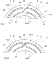
- FIGS. 8 to 10 shows a part of the damper body 20 as seen in the axial direction X, and illustrates a configuration example of the restrictor R.
- the restrictor R (R1) includes a hinderer 51, which is located in a part of, or in the entirety of, the connecting portion 43.
- the inner slit portion 42, the connecting portion 43, and the outer slit portion 44 have substantially the same slit width.
- the hinderer 51 may be located along the slit walls of the connecting portion 43, or may be located at the middle of the slit width of the connecting portion 43.
- the hinderer 51 may be made of a highly thermal-resistant elastomer, or made of a metal.
- the hinderer 51 substantially reduces the cross-sectional area of a passage in the connecting portion 43 in both the circumferential direction and the radial direction.
- the restrictor R (R2) according to the second example shown in FIG. 9 has a third slit width C3.
- the inner slit portion 42 has a first slit width C1
- the outer slit portion 44 has a second slit width C2.
- the first slit width C1 and the second slit width C2 may be the same.
- the third slit width C3 is less than the first slit width C1 and the second slit width C2.
- the restrictor R2 may be a part of the connecting portion 43, or the entire connecting portion 43 may be configured as the restrictor R2.
- the restrictor R2 thus configured restricts the flow of the viscous fluid 5 between the inner slit portion 42 and the outer slit portion 44.
- the restrictor R (R3) according to the third example shown in FIG. 10 is neither a linear passage nor a smooth curved passage, but includes at least one bent portion.
- the restrictor R (R3) may include a zigzag passage with two or more bent portions (i.e., a straight passage bent at an acute angle multiple times).
- the restrictor R3 may be a part of the connecting portion 43, or the entire connecting portion 43 may be configured as the restrictor R3.
- the restrictor R3 thus configured hinders the movement of the viscous fluid 5 from the inner slit portion 42 to the outer slit portion 44 (or from the outer slit portion 44 to the inner slit portion 42).
- the second measure is to prevent a reverse flow of the viscous fluid 5 from the inside of the slits 4 into the fluid feeding holes 27.
- a connecting portion between each fluid feeding hole 27 and its corresponding slit 4 includes a reverse flow preventer 28 (see FIG. 1 ). Since the viscous fluid 5 pushed out of the slit 4 due to vibration during rotation of the rotating shaft 11 is hindered from reversely flowing into the fluid feeding hole 27, a flow of the viscous fluid 5 into the end seal gaps G2 is facilitated.
- the reverse flow preventer 28 serves as a "restrictor" that restricts a flow of the viscous fluid 5.
- the restrictor examples include: a self-forming restrictor configured such that the cross-sectional area of the passage of the fluid feeding hole 27 decreases gradually; and an orifice restrictor realized by an orifice component located in the fluid feeding hole 27.
- a total cross-sectional area of the restrictor passages is desirably equal to, or less than, the cross-sectional area of the outlet passages of the end seal gaps G2.
- the damper 2 is a damper that is located between the rotating shaft 11 and the support (the housing 12), the damper serving to damp vibration of the rotating shaft 11 and to center the rotating shaft 11.
- the damper 2 includes the damper body 20, the sealers 30, and the viscous fluid 5.
- the damper body 20 includes: the inner ring 21 and the outer ring 22, which are concentrically located; the arc springs 23, which are located side by side in the circumferential direction between the inner ring 21 and the outer ring 22; and the slits 4, which separate the inner ring 21, the outer ring 22, and the arc springs 23 from each other.
- the damper body 20 is overall cylindrical.
- the arc springs 23 include the first arc spring and the second arc spring that are located side by side in the circumferential direction.
- Each slit 4 includes: the inner slit portion 42, which separates the first arc spring and the inner ring 21 from each other; the outer slit portion 44, which separates the second arc spring and the outer ring 22 from each other; and the connecting portion 43, which connects the inner slit portion 42 and the outer slit portion 44.
- the connecting portion 43 includes the restrictor R (R1, R2, R3), which restricts the movement of the viscous fluid 5 between the inner slit portion 42 and the outer slit portion 44.
- the restrictor R1 may include the hinderer 51, which is located in a part of, or in the entirety of, the connecting portion 43.
- the hinderer 51 hinders a flow of the viscous fluid 5 in one of, or both, the circumferential direction and the radial direction.
- the restrictor R2 may have the third slit width C3, which is less than the first slit width and the second slit width C2.
- the inner slit portion 42 has the first slit width C1
- the outer slit portion 44 has the second slit width C2.
- the restrictor R3 may include at least one bent portion.
- the damper 2 configured as above includes a fluid film that is continuous in the slits 4 and the end seal gaps G2.
- pressure derived from the viscosity of the viscous fluid 5 occurs in the fluid film in the slits 4 (i.e., in the squeeze gaps G1). Accordingly, vibration damping (so-called squeeze damping) occurs.
- the arc springs 23 support the rotating shaft 11 softly, and center the rotating shaft 11. Also, when the rotating shaft 11 vibrates due to its rotation, viscous resistance occurs in the fluid film in the end seal gaps G2. Consequently, vibration damping by energy dissipation (so-called dashpot damping) occurs.
- the dashpot damping effect exerted by the end seal gaps G2 will compensate for the insufficiency in the vibration damping effect, or even improve the vibration damping effect.
- the damper body 20 may include at least one fluid feeding hole 27, which extends in the radial direction from the outer surface of the outer ring 22, communicates with at least one of the slits 4, and feeds the viscous fluid 5 to the at least one of the slits 4.
- the fluid feeding hole 27 may include the reverse flow preventer 28, which prevents a reverse flow of the viscous fluid 5 from the at least one of the slits 4 to the fluid feeding hole 27.
- the reverse flow preventer 28 is a restrictor that restricts a flow of the viscous fluid 5.
- the damper 2 since vibration damping occurs in the end seal gaps G2, even in a case where the slit width C of the slits 4 is set greater than the slit width in conventional squeeze film dampers and thereby the squeeze damping effect exerted by the slits 4 is lowered, the dashpot damping effect exerted by the end seal gaps G2 will compensate for the insufficiency in the vibration damping effect, or even improve the vibration damping effect.
- the slit width C of the slits 4 can be increased compared to the slit width in conventional squeeze film dampers while maintaining or improving vibration damping characteristics compared to conventional squeeze film dampers.
- the slit width C of the slits 4 can be increased to such an extent that the damping characteristics of the damper 2 are hardly affected by the static eccentricity and vibration amplitude of the rotating shaft 11.
- the dependence of the damping characteristics of the damper 2 on the static eccentricity of the rotating shaft 11 is lowered, which makes it easier to properly design the damper 2.
- the dependence of the damping characteristics of the damper 2 on the vibration amplitude of the rotating shaft 11 is lowered, which makes it possible to suppress the occurrence of an unwanted phenomenon such as a jump phenomenon caused by a rapid change in the vibration of the rotating shaft 11.
- the machining current can be increased and thereby the machining time can be shortened, which consequently makes it possible to reduce the manufacturing cost of the damper 2.
- the sealers 30 include the coupling surfaces 32 or 33, respectively, and further include the sealing surfaces 31, respectively.
- the coupling surfaces 32 or 33 are coupled to the outer ring 22, or the inner ring 21, of the damper body 20.
- the sealing surfaces 31 are recessed relative to the coupling surfaces 32 or 33.
- surfaces of the respective sealers 30, the surfaces facing the damper body 20, are stepped, and these stepped surfaces form the end seal gaps G2. In this manner, the formation of the end seal gaps G2 with a stable gap dimension is achieved.
- surfaces of the damper body 20, the surfaces facing the respective sealers 30, may be stepped, and these stepped surfaces may form the end seal gaps G2.
- the sealers 30 may be fixed to the outer ring 22, or the inner ring 21, of the damper body 20 via the thin plates 35 or 36, respectively, the thin plates each having a thickness corresponding to the gap dimension of each of the end seal gaps G2.
- the gap dimension of the end seal gaps G2 can be readily adjusted by the thickness of the thin plates 35 or 36.
- the diameter of a circle that passes between the inner peripheral edge and the outer peripheral edge of each of the arc springs 23 at the middle between the inner peripheral edge and the outer peripheral edge in the radial direction is an arc spring center diameter D
- the ratio of the slit width C of at least one part of each slit 4 to the arc spring center diameter D is not less than 1/100.
- the slit width C which is set as above, is sufficiently greater than the slit width of conventional squeeze film dampers (the conventional slit width is, for example, 0.2 mm as disclosed in Patent Literature 1).
- the wire diameter can be increased compared to the conventional art, and thereby the machining current can be increased. Consequently, the machining time is shortened, which consequently makes it possible to reduce the manufacturing cost of the damper 2.
- the damper 2 having such a slit width C can suppress influences of the static eccentricity and vibration amplitude on the vibration damping performance.
- the number of arc springs 23 is four, and also, the number of slits 4 is four.
- the number of arc springs 23 and the number of slits 4 are not limited to four.
- a damper body 20A in which two arc springs 23 are located side by side in the circumferential direction and the number of slits 4 is two, is adoptable in the damper 2.
Landscapes
- Engineering & Computer Science (AREA)
- General Engineering & Computer Science (AREA)
- Mechanical Engineering (AREA)
- Physics & Mathematics (AREA)
- Acoustics & Sound (AREA)
- Aviation & Aerospace Engineering (AREA)
- Fluid-Damping Devices (AREA)
- Support Of The Bearing (AREA)
- Vibration Prevention Devices (AREA)
Applications Claiming Priority (2)
| Application Number | Priority Date | Filing Date | Title |
|---|---|---|---|
| JP2020102877A JP7421424B2 (ja) | 2020-06-15 | 2020-06-15 | ダンパ |
| PCT/JP2021/022115 WO2021256372A1 (ja) | 2020-06-15 | 2021-06-10 | ダンパ |
Publications (2)
| Publication Number | Publication Date |
|---|---|
| EP4166804A1 true EP4166804A1 (de) | 2023-04-19 |
| EP4166804A4 EP4166804A4 (de) | 2024-10-23 |
Family
ID=79197665
Family Applications (1)
| Application Number | Title | Priority Date | Filing Date |
|---|---|---|---|
| EP21826714.4A Pending EP4166804A4 (de) | 2020-06-15 | 2021-06-10 | Dämpfer |
Country Status (5)
| Country | Link |
|---|---|
| US (1) | US12181015B2 (de) |
| EP (1) | EP4166804A4 (de) |
| JP (1) | JP7421424B2 (de) |
| CN (1) | CN115667759A (de) |
| WO (1) | WO2021256372A1 (de) |
Families Citing this family (3)
| Publication number | Priority date | Publication date | Assignee | Title |
|---|---|---|---|---|
| US12392372B2 (en) * | 2024-01-30 | 2025-08-19 | Miba Industrial Bearings U.S. LLC | Squeeze film damper and a rotating machinery |
| CN117869704B (zh) * | 2024-03-12 | 2024-05-31 | 山东职业学院 | 一种热力管道安装防护装置 |
| CN118149049B (zh) * | 2024-05-11 | 2024-07-12 | 杭州华翊科技有限公司 | 整体式挤压油膜阻尼器以及涡喷发动机的转子润滑系统 |
Family Cites Families (16)
| Publication number | Priority date | Publication date | Assignee | Title |
|---|---|---|---|---|
| US4872767A (en) | 1985-04-03 | 1989-10-10 | General Electric Company | Bearing support |
| US5421655A (en) * | 1987-05-29 | 1995-06-06 | Kmc, Inc. | Fluid dampened support having variable stiffness and damping |
| US5531522A (en) | 1987-05-29 | 1996-07-02 | Kmc, Inc. | Fluid dampened support having variable stiffness and damping |
| JPH0357541U (de) * | 1989-07-31 | 1991-06-03 | ||
| DE19613471A1 (de) * | 1996-04-04 | 1997-10-09 | Asea Brown Boveri | Lagerabstützung für schnellaufende Rotoren |
| JP3645669B2 (ja) * | 1996-10-07 | 2005-05-11 | 株式会社エクセディ | 粘性ダンパー機構 |
| JPH11141545A (ja) * | 1997-11-07 | 1999-05-25 | Mitsubishi Heavy Ind Ltd | スクイーズフィルムダンパー軸受 |
| DE19834111A1 (de) * | 1998-07-29 | 2000-02-03 | Asea Brown Boveri | Radiallager |
| JP2007056976A (ja) * | 2005-08-24 | 2007-03-08 | Ishikawajima Harima Heavy Ind Co Ltd | 軸受のダンパ要素及びその製造方法、並びにガスタービンエンジン |
| JP2010203504A (ja) | 2009-03-03 | 2010-09-16 | Ihi Corp | スクイーズフィルムダンパ軸受 |
| JP6145040B2 (ja) * | 2013-12-26 | 2017-06-07 | 三菱重工業株式会社 | 軸受装置、及び回転機械 |
| US9879720B2 (en) * | 2016-05-05 | 2018-01-30 | General Electric Company | Bearing damper with external support spring systems and methods |
| BE1025345B1 (nl) * | 2017-06-26 | 2019-02-05 | Atlas Copco Airpower Naamloze Vennootschap | Lagerdemperelement, lager en compressorelement uitgerust met dergelijk lagerdemperelement en werkwijze om dergelijk lagerdemperelement te vervaardigen |
| JP7021920B2 (ja) * | 2017-11-30 | 2022-02-17 | 三菱重工業株式会社 | 軸受装置及び回転機械 |
| CN110566614B (zh) * | 2019-09-11 | 2022-03-22 | 哈尔滨工业大学(深圳) | 一种单向平面扭簧 |
| BE1028709B1 (nl) * | 2020-10-19 | 2022-05-16 | Atlas Copco Airpower Nv | Meertraps centrifugaalcompressor |
-
2020
- 2020-06-15 JP JP2020102877A patent/JP7421424B2/ja active Active
-
2021
- 2021-06-10 WO PCT/JP2021/022115 patent/WO2021256372A1/ja not_active Ceased
- 2021-06-10 EP EP21826714.4A patent/EP4166804A4/de active Pending
- 2021-06-10 CN CN202180042008.2A patent/CN115667759A/zh active Pending
- 2021-06-10 US US18/010,605 patent/US12181015B2/en active Active
Also Published As
| Publication number | Publication date |
|---|---|
| US20230258240A1 (en) | 2023-08-17 |
| CN115667759A (zh) | 2023-01-31 |
| JP2021195996A (ja) | 2021-12-27 |
| WO2021256372A1 (ja) | 2021-12-23 |
| JP7421424B2 (ja) | 2024-01-24 |
| US12181015B2 (en) | 2024-12-31 |
| EP4166804A4 (de) | 2024-10-23 |
Similar Documents
| Publication | Publication Date | Title |
|---|---|---|
| US12181015B2 (en) | Damper | |
| KR100715921B1 (ko) | 저널 베어링 | |
| US4872767A (en) | Bearing support | |
| US8083413B2 (en) | Compliant hybrid gas journal bearing using integral wire mesh dampers | |
| US9638059B2 (en) | Exhaust-gas turbocharger | |
| EP2392783B1 (de) | Turbolader mit Lager mit Flüssigkeitsfilmdämpfung und Zentrierfedern | |
| US6450688B2 (en) | Fluid bearing having a foil assembly | |
| EP4166801A1 (de) | Kippsegmentlager | |
| US5245890A (en) | Resilient coupling with relative rotation limitation | |
| CN102192241A (zh) | 具有折叠突片的无键/无槽箔片轴承 | |
| JP6896894B2 (ja) | ベアリング減衰器要素、そのようなベアリング減衰器要素が設けられたベアリング及び圧縮器要素、及びそのようなベアリング減衰器要素を製造する方法 | |
| EP4012207B1 (de) | Radiales luftfoliengleitlager | |
| CN86102491A (zh) | 旋转机械的密封装置 | |
| KR20230124921A (ko) | 압축기, 디스크 본체 및 시일 | |
| CN114453603A (zh) | 一种电主轴及具有其的数控机床 | |
| AU2019339800A1 (en) | Damper bearing and damper | |
| US20230160470A1 (en) | Shaft mounting assembly | |
| JPS6331001B2 (de) | ||
| JP3900599B2 (ja) | ターボチャージャの軸受構造 | |
| WO2024257664A1 (ja) | 回転機械 | |
| US20250207629A1 (en) | Airfoil journal bearing | |
| WO2024135467A1 (ja) | シールリング | |
| WO1996013677A1 (en) | Dampened dry running gas seal | |
| JPH0198710A (ja) | 静圧気体軸受 | |
| JPS61153012A (ja) | 制振軸受 |
Legal Events
| Date | Code | Title | Description |
|---|---|---|---|
| STAA | Information on the status of an ep patent application or granted ep patent |
Free format text: STATUS: THE INTERNATIONAL PUBLICATION HAS BEEN MADE |
|
| PUAI | Public reference made under article 153(3) epc to a published international application that has entered the european phase |
Free format text: ORIGINAL CODE: 0009012 |
|
| STAA | Information on the status of an ep patent application or granted ep patent |
Free format text: STATUS: REQUEST FOR EXAMINATION WAS MADE |
|
| 17P | Request for examination filed |
Effective date: 20230111 |
|
| AK | Designated contracting states |
Kind code of ref document: A1 Designated state(s): AL AT BE BG CH CY CZ DE DK EE ES FI FR GB GR HR HU IE IS IT LI LT LU LV MC MK MT NL NO PL PT RO RS SE SI SK SM TR |
|
| DAV | Request for validation of the european patent (deleted) | ||
| DAX | Request for extension of the european patent (deleted) | ||
| A4 | Supplementary search report drawn up and despatched |
Effective date: 20240620 |
|
| RIC1 | Information provided on ipc code assigned before grant |
Ipc: F16F 15/06 20060101ALI20240614BHEP Ipc: F16F 15/023 20060101ALI20240614BHEP Ipc: F16F 9/10 20060101ALI20240614BHEP Ipc: F16C 27/00 20060101AFI20240614BHEP |
|
| DA4 | Supplementary search report drawn up and despatched (deleted) | ||
| RIC1 | Information provided on ipc code assigned before grant |
Ipc: F16F 15/06 20060101ALI20240912BHEP Ipc: F16F 15/023 20060101ALI20240912BHEP Ipc: F16F 9/10 20060101ALI20240912BHEP Ipc: F16C 27/00 20060101AFI20240912BHEP |
|
| RA4 | Supplementary search report drawn up and despatched (corrected) |
Effective date: 20240916 |
|
| GRAP | Despatch of communication of intention to grant a patent |
Free format text: ORIGINAL CODE: EPIDOSNIGR1 |
|
| STAA | Information on the status of an ep patent application or granted ep patent |
Free format text: STATUS: GRANT OF PATENT IS INTENDED |
|
| INTG | Intention to grant announced |
Effective date: 20250430 |
|
| GRAJ | Information related to disapproval of communication of intention to grant by the applicant or resumption of examination proceedings by the epo deleted |
Free format text: ORIGINAL CODE: EPIDOSDIGR1 |
|
| STAA | Information on the status of an ep patent application or granted ep patent |
Free format text: STATUS: REQUEST FOR EXAMINATION WAS MADE |
|
| INTC | Intention to grant announced (deleted) | ||
| GRAP | Despatch of communication of intention to grant a patent |
Free format text: ORIGINAL CODE: EPIDOSNIGR1 |
|
| STAA | Information on the status of an ep patent application or granted ep patent |
Free format text: STATUS: GRANT OF PATENT IS INTENDED |