EP4166766A1 - Longitudinally flushed large-scale diesel engine - Google Patents
Longitudinally flushed large-scale diesel engine Download PDFInfo
- Publication number
- EP4166766A1 EP4166766A1 EP21202858.3A EP21202858A EP4166766A1 EP 4166766 A1 EP4166766 A1 EP 4166766A1 EP 21202858 A EP21202858 A EP 21202858A EP 4166766 A1 EP4166766 A1 EP 4166766A1
- Authority
- EP
- European Patent Office
- Prior art keywords
- piston rod
- diesel engine
- large diesel
- piston
- engine according
- Prior art date
- Legal status (The legal status is an assumption and is not a legal conclusion. Google has not performed a legal analysis and makes no representation as to the accuracy of the status listed.)
- Withdrawn
Links
- 238000002485 combustion reaction Methods 0.000 claims abstract description 48
- 230000006835 compression Effects 0.000 claims abstract description 37
- 238000007906 compression Methods 0.000 claims abstract description 37
- 239000000446 fuel Substances 0.000 claims description 66
- 239000007788 liquid Substances 0.000 claims description 29
- 239000000463 material Substances 0.000 claims description 29
- 238000004519 manufacturing process Methods 0.000 claims description 8
- 238000007789 sealing Methods 0.000 claims description 6
- 239000007789 gas Substances 0.000 description 52
- 238000002347 injection Methods 0.000 description 13
- 239000007924 injection Substances 0.000 description 13
- 239000000203 mixture Substances 0.000 description 11
- 238000013461 design Methods 0.000 description 9
- 230000002000 scavenging effect Effects 0.000 description 9
- 239000000295 fuel oil Substances 0.000 description 6
- 238000000034 method Methods 0.000 description 6
- 230000008569 process Effects 0.000 description 6
- 230000008901 benefit Effects 0.000 description 5
- 238000012423 maintenance Methods 0.000 description 5
- 239000003921 oil Substances 0.000 description 5
- 239000002283 diesel fuel Substances 0.000 description 4
- 239000003949 liquefied natural gas Substances 0.000 description 4
- 239000003915 liquefied petroleum gas Substances 0.000 description 4
- VNWKTOKETHGBQD-UHFFFAOYSA-N methane Chemical compound C VNWKTOKETHGBQD-UHFFFAOYSA-N 0.000 description 4
- 238000005240 physical vapour deposition Methods 0.000 description 4
- OKKJLVBELUTLKV-UHFFFAOYSA-N Methanol Chemical compound OC OKKJLVBELUTLKV-UHFFFAOYSA-N 0.000 description 3
- 238000001816 cooling Methods 0.000 description 3
- VYZAMTAEIAYCRO-UHFFFAOYSA-N Chromium Chemical compound [Cr] VYZAMTAEIAYCRO-UHFFFAOYSA-N 0.000 description 2
- OTMSDBZUPAUEDD-UHFFFAOYSA-N Ethane Chemical compound CC OTMSDBZUPAUEDD-UHFFFAOYSA-N 0.000 description 2
- LFQSCWFLJHTTHZ-UHFFFAOYSA-N Ethanol Chemical compound CCO LFQSCWFLJHTTHZ-UHFFFAOYSA-N 0.000 description 2
- 229910000831 Steel Inorganic materials 0.000 description 2
- 238000000576 coating method Methods 0.000 description 2
- 239000000567 combustion gas Substances 0.000 description 2
- 239000000839 emulsion Substances 0.000 description 2
- 238000010438 heat treatment Methods 0.000 description 2
- 239000010763 heavy fuel oil Substances 0.000 description 2
- 238000003754 machining Methods 0.000 description 2
- 238000012544 monitoring process Methods 0.000 description 2
- 239000003345 natural gas Substances 0.000 description 2
- 238000012545 processing Methods 0.000 description 2
- 239000010959 steel Substances 0.000 description 2
- 239000000725 suspension Substances 0.000 description 2
- 230000007704 transition Effects 0.000 description 2
- 238000011282 treatment Methods 0.000 description 2
- 238000003466 welding Methods 0.000 description 2
- 150000001298 alcohols Chemical class 0.000 description 1
- 230000008859 change Effects 0.000 description 1
- 239000002817 coal dust Substances 0.000 description 1
- 239000011248 coating agent Substances 0.000 description 1
- 230000001419 dependent effect Effects 0.000 description 1
- 238000010892 electric spark Methods 0.000 description 1
- 239000012530 fluid Substances 0.000 description 1
- 238000000227 grinding Methods 0.000 description 1
- 229930195733 hydrocarbon Natural products 0.000 description 1
- 150000002430 hydrocarbons Chemical class 0.000 description 1
- 239000010687 lubricating oil Substances 0.000 description 1
- 238000005457 optimization Methods 0.000 description 1
- 230000000737 periodic effect Effects 0.000 description 1
- 239000003208 petroleum Substances 0.000 description 1
- 230000009467 reduction Effects 0.000 description 1
- 230000001105 regulatory effect Effects 0.000 description 1
- 238000004381 surface treatment Methods 0.000 description 1
- XLYOFNOQVPJJNP-UHFFFAOYSA-N water Substances O XLYOFNOQVPJJNP-UHFFFAOYSA-N 0.000 description 1
Images


Classifications
-
- F—MECHANICAL ENGINEERING; LIGHTING; HEATING; WEAPONS; BLASTING
- F02—COMBUSTION ENGINES; HOT-GAS OR COMBUSTION-PRODUCT ENGINE PLANTS
- F02B—INTERNAL-COMBUSTION PISTON ENGINES; COMBUSTION ENGINES IN GENERAL
- F02B25/00—Engines characterised by using fresh charge for scavenging cylinders
- F02B25/02—Engines characterised by using fresh charge for scavenging cylinders using unidirectional scavenging
-
- F—MECHANICAL ENGINEERING; LIGHTING; HEATING; WEAPONS; BLASTING
- F02—COMBUSTION ENGINES; HOT-GAS OR COMBUSTION-PRODUCT ENGINE PLANTS
- F02D—CONTROLLING COMBUSTION ENGINES
- F02D15/00—Varying compression ratio
- F02D15/02—Varying compression ratio by alteration or displacement of piston stroke
-
- F—MECHANICAL ENGINEERING; LIGHTING; HEATING; WEAPONS; BLASTING
- F02—COMBUSTION ENGINES; HOT-GAS OR COMBUSTION-PRODUCT ENGINE PLANTS
- F02B—INTERNAL-COMBUSTION PISTON ENGINES; COMBUSTION ENGINES IN GENERAL
- F02B25/00—Engines characterised by using fresh charge for scavenging cylinders
- F02B25/02—Engines characterised by using fresh charge for scavenging cylinders using unidirectional scavenging
- F02B25/04—Engines having ports both in cylinder head and in cylinder wall near bottom of piston stroke
-
- F—MECHANICAL ENGINEERING; LIGHTING; HEATING; WEAPONS; BLASTING
- F02—COMBUSTION ENGINES; HOT-GAS OR COMBUSTION-PRODUCT ENGINE PLANTS
- F02B—INTERNAL-COMBUSTION PISTON ENGINES; COMBUSTION ENGINES IN GENERAL
- F02B75/00—Other engines
- F02B75/02—Engines characterised by their cycles, e.g. six-stroke
-
- F—MECHANICAL ENGINEERING; LIGHTING; HEATING; WEAPONS; BLASTING
- F02—COMBUSTION ENGINES; HOT-GAS OR COMBUSTION-PRODUCT ENGINE PLANTS
- F02B—INTERNAL-COMBUSTION PISTON ENGINES; COMBUSTION ENGINES IN GENERAL
- F02B75/00—Other engines
- F02B75/04—Engines with variable distances between pistons at top dead-centre positions and cylinder heads
- F02B75/044—Engines with variable distances between pistons at top dead-centre positions and cylinder heads by means of an adjustable piston length
-
- F—MECHANICAL ENGINEERING; LIGHTING; HEATING; WEAPONS; BLASTING
- F02—COMBUSTION ENGINES; HOT-GAS OR COMBUSTION-PRODUCT ENGINE PLANTS
- F02B—INTERNAL-COMBUSTION PISTON ENGINES; COMBUSTION ENGINES IN GENERAL
- F02B75/00—Other engines
- F02B75/32—Engines characterised by connections between pistons and main shafts and not specific to preceding main groups
-
- F—MECHANICAL ENGINEERING; LIGHTING; HEATING; WEAPONS; BLASTING
- F02—COMBUSTION ENGINES; HOT-GAS OR COMBUSTION-PRODUCT ENGINE PLANTS
- F02D—CONTROLLING COMBUSTION ENGINES
- F02D15/00—Varying compression ratio
- F02D15/04—Varying compression ratio by alteration of volume of compression space without changing piston stroke
-
- F—MECHANICAL ENGINEERING; LIGHTING; HEATING; WEAPONS; BLASTING
- F02—COMBUSTION ENGINES; HOT-GAS OR COMBUSTION-PRODUCT ENGINE PLANTS
- F02D—CONTROLLING COMBUSTION ENGINES
- F02D19/00—Controlling engines characterised by their use of non-liquid fuels, pluralities of fuels, or non-fuel substances added to the combustible mixtures
- F02D19/06—Controlling engines characterised by their use of non-liquid fuels, pluralities of fuels, or non-fuel substances added to the combustible mixtures peculiar to engines working with pluralities of fuels, e.g. alternatively with light and heavy fuel oil, other than engines indifferent to the fuel consumed
- F02D19/08—Controlling engines characterised by their use of non-liquid fuels, pluralities of fuels, or non-fuel substances added to the combustible mixtures peculiar to engines working with pluralities of fuels, e.g. alternatively with light and heavy fuel oil, other than engines indifferent to the fuel consumed simultaneously using pluralities of fuels
-
- F—MECHANICAL ENGINEERING; LIGHTING; HEATING; WEAPONS; BLASTING
- F02—COMBUSTION ENGINES; HOT-GAS OR COMBUSTION-PRODUCT ENGINE PLANTS
- F02B—INTERNAL-COMBUSTION PISTON ENGINES; COMBUSTION ENGINES IN GENERAL
- F02B75/00—Other engines
- F02B75/02—Engines characterised by their cycles, e.g. six-stroke
- F02B2075/022—Engines characterised by their cycles, e.g. six-stroke having less than six strokes per cycle
- F02B2075/025—Engines characterised by their cycles, e.g. six-stroke having less than six strokes per cycle two
-
- F—MECHANICAL ENGINEERING; LIGHTING; HEATING; WEAPONS; BLASTING
- F02—COMBUSTION ENGINES; HOT-GAS OR COMBUSTION-PRODUCT ENGINE PLANTS
- F02B—INTERNAL-COMBUSTION PISTON ENGINES; COMBUSTION ENGINES IN GENERAL
- F02B75/00—Other engines
- F02B75/02—Engines characterised by their cycles, e.g. six-stroke
- F02B2075/022—Engines characterised by their cycles, e.g. six-stroke having less than six strokes per cycle
- F02B2075/027—Engines characterised by their cycles, e.g. six-stroke having less than six strokes per cycle four
-
- F—MECHANICAL ENGINEERING; LIGHTING; HEATING; WEAPONS; BLASTING
- F02—COMBUSTION ENGINES; HOT-GAS OR COMBUSTION-PRODUCT ENGINE PLANTS
- F02D—CONTROLLING COMBUSTION ENGINES
- F02D19/00—Controlling engines characterised by their use of non-liquid fuels, pluralities of fuels, or non-fuel substances added to the combustible mixtures
- F02D19/06—Controlling engines characterised by their use of non-liquid fuels, pluralities of fuels, or non-fuel substances added to the combustible mixtures peculiar to engines working with pluralities of fuels, e.g. alternatively with light and heavy fuel oil, other than engines indifferent to the fuel consumed
- F02D19/08—Controlling engines characterised by their use of non-liquid fuels, pluralities of fuels, or non-fuel substances added to the combustible mixtures peculiar to engines working with pluralities of fuels, e.g. alternatively with light and heavy fuel oil, other than engines indifferent to the fuel consumed simultaneously using pluralities of fuels
- F02D19/10—Controlling engines characterised by their use of non-liquid fuels, pluralities of fuels, or non-fuel substances added to the combustible mixtures peculiar to engines working with pluralities of fuels, e.g. alternatively with light and heavy fuel oil, other than engines indifferent to the fuel consumed simultaneously using pluralities of fuels peculiar to compression-ignition engines in which the main fuel is gaseous
-
- F—MECHANICAL ENGINEERING; LIGHTING; HEATING; WEAPONS; BLASTING
- F02—COMBUSTION ENGINES; HOT-GAS OR COMBUSTION-PRODUCT ENGINE PLANTS
- F02D—CONTROLLING COMBUSTION ENGINES
- F02D2400/00—Control systems adapted for specific engine types; Special features of engine control systems not otherwise provided for; Power supply, connectors or cabling for engine control systems
- F02D2400/04—Two-stroke combustion engines with electronic control
-
- Y—GENERAL TAGGING OF NEW TECHNOLOGICAL DEVELOPMENTS; GENERAL TAGGING OF CROSS-SECTIONAL TECHNOLOGIES SPANNING OVER SEVERAL SECTIONS OF THE IPC; TECHNICAL SUBJECTS COVERED BY FORMER USPC CROSS-REFERENCE ART COLLECTIONS [XRACs] AND DIGESTS
- Y02—TECHNOLOGIES OR APPLICATIONS FOR MITIGATION OR ADAPTATION AGAINST CLIMATE CHANGE
- Y02T—CLIMATE CHANGE MITIGATION TECHNOLOGIES RELATED TO TRANSPORTATION
- Y02T10/00—Road transport of goods or passengers
- Y02T10/10—Internal combustion engine [ICE] based vehicles
- Y02T10/30—Use of alternative fuels, e.g. biofuels
Definitions
- the invention relates to a large diesel engine according to the preamble of the independent patent claim.
- Large diesel engines are traditionally operated with heavy fuel oil.
- Large diesel engines which can be designed as two-stroke or four-stroke machines, for example as longitudinally scavenged two-stroke large diesel engines, are often used as drive units for ships or in stationary operation, e.g. to drive large generators to generate electrical energy.
- the motors usually run continuously for considerable periods of time, which places high demands on operational reliability and availability. Long maintenance intervals, low wear and economical use of operating materials are therefore key criteria for the operator.
- Large diesel engines typically have cylinders with an inside diameter (bore) of at least 200 mm.
- large diesel engines with a bore of up to 960 mm or even more are used.
- liquid fuels are used, ie fuels that are introduced into the combustion chamber in a liquid state as well as gaseous fuels, i.e. fuels that are introduced into the combustion chamber in a gaseous state.
- liquid fuels as known alternatives to heavy oil are other heavy hydrocarbons, which remain in particular as residues in petroleum refineries, alcohols, in particular methanol or ethanol, petrol, diesel, or else emulsions or suspensions. It is e.g. For example, it is known to use emulsions referred to as MSAR (Multiphase Superfine Atomized Residue) as fuel.
- MSAR Multiphase Superfine Atomized Residue
- a well-known suspension is that of coal dust and water, which is also used as a fuel for large engines.
- Natural gases such as LNG (liquefied natural gas), liquid gases such as LPG (liquefied petroleum gas) or ethane are known as gaseous fuels.
- such large diesel engines are also known which can be operated with at least two different fuels, the engine being operated with either one fuel or the other fuel, depending on the operating situation or the environment.
- An example of a large diesel engine that can be operated with two different fuels is a large diesel engine that is designed as a dual-fuel large diesel engine. This is operable in a liquid mode in which a liquid fuel is introduced into the cylinder for combustion, and in a gas mode in which a gas is introduced into the cylinder as fuel.
- large diesel engine refers to engines that can be operated at least in diesel mode.
- large diesel engine also includes such large dual-fuel engines that can be operated in another mode, for example Otto mode, in addition to diesel mode.
- gas mode or “operation in gas mode” means that only the gas or gaseous fuel for the torque-generating combustion is used as fuel.
- a small amount of a self-igniting liquid fuel such as B. heavy oil, is injected to perform the spark ignition, but still the combustion process that produces the torque is entirely gas or gaseous fuel driven.
- pilot injection This spark ignition process by self-igniting a small amount of liquid fuel is sometimes referred to as pilot injection.
- This pilot injection has nothing to do with the injection of liquid fuel into the combustion chamber when the large engine is operated in liquid mode.
- a different injection device is usually used for the pilot injection than for injecting the liquid fuel in liquid mode.
- the small amount of liquid fuel is often not injected directly into the combustion chamber, but rather into at least one antechamber, which is connected to the combustion chamber via a duct.
- the gas inlet opening(s) are arranged at such a height between the lower reversal point and the upper reversal point of the piston movement that the gas can be introduced into the cylinder during the upward movement of the piston as long as no or at least no significant compression has taken place in the cylinder .
- Large diesel engines are usually designed in such a way that the compression ratio is optimized at the 100% load point, i.e. at full load, and the large diesel engine has the best possible compromise between combustion behavior and efficiency there, i.e. the large diesel engines are designed in such a way that they have the highest possible thermodynamic efficiency at the 100% load point, i.e. at full load and maximum speed.
- the compression ratio is a geometric variable which is the ratio of a first volume of the combustion chamber before the compression of the air-fuel mixture to a remaining second volume of the combustion chamber after compression of the air-fuel mixture.
- the optimization of the combustion behavior at the 100% load point means that the efficiency of the large diesel engine is no longer optimal in lower load ranges, for example at a lower mean pressure.
- VCR Variable Compression Ratio
- a large diesel engine is proposed, with at least one cylinder, which has a combustion chamber that is delimited by a piston, which is arranged such that it can be moved back and forth along a cylinder axis, and with a rotatable crankshaft, the piston being connected to a crosshead via a piston rod which has a crosshead journal, the crosshead being connected to the crankshaft via a connecting rod, the piston rod being arranged in the crosshead journal, and a control device being provided for setting a compression ratio, with which the piston rod is moved relative to the crosshead journal in the direction of the cylinder axis is movable.
- the piston rod comprises a lower part and an upper part, the lower part being arranged in the crosshead pin, the upper part connecting the piston to the lower part, and the lower part and the upper part being detachably connected to each other.
- This configuration of the piston rod with a lower part and with an upper part represents a particularly advantageous and economical embodiment with which the compression ratio in the cylinder can be changed.
- the lower part of the piston rod which is arranged in the crosshead pin and is exposed to very high loads during operation, can be manufactured from a higher-quality material and/or with greater precision than the upper part of the piston rod, which is made from a less expensive material and/or can be manufactured with lower precision requirements.
- the configuration also has advantages with regard to maintenance or service work. If, for example, the piston and the piston rod are to be removed from the cylinder as part of maintenance work, the lower part of the piston rod can remain in the crosshead pin in the configuration according to the invention, while the piston together with the upper part of the piston rod are removed from the cylinder is pulled out. Thus, the lower part, which remains in the crosshead, is much better protected.
- the configuration of the piston rod with the lower and the upper part is also very advantageous with regard to production. Machining the lower part is much easier. Bores in the lower part, which are required, for example, for supplying and removing cooling oil that is routed through the piston rod to the piston in the operating state, can be made much more simply, namely directly from the upper side of the lower part. It is no longer necessary to carry out such productions from the upper end, that is to say from the end of the piston rod which is connected to the piston.
- the overall machining of the lower part is much easier because it can be manufactured separately from the rest of the piston rod.
- the lower part which must be fitted into the crosshead pin of the crosshead, usually requires a significantly higher level of precision, which can be achieved much more easily if the lower part is manufactured separately.
- Other processing steps on the lower part such as grinding operations, surface treatments, e.g. B. surface hardening, surface coatings, e.g. with chrome, using PVD (PVD: Physical Vapor Deposition), using build-up welding or heat treatments are much easier to carry out because the lower part can be manufactured and machined separately from the rest of the piston rod.
- PVD Physical Vapor Deposition
- the lower part of the piston rod is designed as a hydraulic piston which delimits a hydraulic chamber which is arranged in the crosshead pin.
- the control device for setting the compression ratio is then designed as a hydraulic device.
- a hydraulic medium for example an oil
- the piston rod can be moved relative to the lower part designed as a hydraulic piston Crosshead pins are shifted in the direction of the cylinder axis, so that the minimum volume of the combustion chamber is reduced.
- the piston rod can be lowered relative to the crosshead pin, so that the minimum volume of the combustion chamber is increased.
- the lower part of the piston rod is designed as a hydraulic piston
- the high requirement for the precise design of the hydraulic piston can thus be achieved much more easily.
- the lower part is made of a first material and the upper part is made of a second material, the first material being different from the second material.
- the first material is preferably a material with high strength that can withstand the strong mechanical stresses, especially when the lower part is provided with the bores for example cooling oil, lubricating oil or other fluids.
- the second material is preferably a less expensive material, for example steel, as a result of which the production costs can be reduced.
- the first material is the same material as the second material, i.e. the lower part and the upper part of the piston rod consist of the same material.
- the lower part has a first length in the direction of the cylinder axis
- the upper part has a second length in the direction of the cylinder axis, the second length being at least three times, preferably at least five times, the first length is.
- the boundary between the lower part and the upper part of the piston rod is preferably arranged such that the lower part of the piston rod is always located below a sealing arrangement which seals the passage of the piston rod into the cylinder during operation of the large diesel engine.
- the passage of the piston rod into the cylinder in a large diesel engine is usually sealed by means of a stuffing box. Then the boundary between the lower and the upper part of the piston rod is arranged in such a way that this boundary does not move through the stuffing box, but always remains below the stuffing box during the working movement of the piston.
- the lower part of the piston rod has an upper end connected to a lower end of the upper part of the piston rod.
- the upper end of the lower part of the piston rod has a larger outside diameter than the lower end of the upper part of the piston rod.
- the upper end of the lower part of the piston rod has the same outside diameter as the lower end of the upper part of the piston rod.
- the upper end of the lower part of the piston rod has a recess which accommodates the lower end of the upper part of the piston rod.
- the upper end of the lower part of the piston rod completely surrounds the lower end of the upper part.
- the lower end of the upper part of the piston rod has a seat which receives the upper end of the lower part of the piston rod.
- the lower end of the upper part of the piston rod completely surrounds the upper end of the lower part.
- the production of the lower part preferably includes surface hardening.
- the large diesel engine is preferably designed as a longitudinally scavenged two-stroke large diesel engine.
- the large diesel engine is particularly preferably designed as a dual-fuel large diesel engine which can be operated in a liquid mode, in which a liquid fuel is introduced into the combustion chamber for combustion, and which can also be operated in a gas mode, in which a gas for combustion is introduced into the combustion chamber is introduced.
- large diesel engine means such engines as are usually used as the main propulsion units for ships or in stationary operation, e.g. for driving large generators for generating electrical energy.
- the cylinders of a large diesel engine each have an inside diameter (bore) of at least about 200 mm.
- longitudinally scavenged means that the scavenging or charge air is introduced into the cylinder in the region of the lower end. The combustion residues, in particular the exhaust gases, are discharged at the upper end of the cylinder.
- a large diesel engine that is designed as a dual-fuel large diesel engine, ie as an engine that can be operated with two different fuels.
- the dual-fuel large diesel engine can be operated in a liquid mode in which only a liquid fuel is injected into a combustion chamber of a cylinder.
- the liquid fuel for example heavy oil or diesel oil, is usually injected directly into the combustion chamber at a suitable time and ignites there according to the diesel principle of self-ignition.
- the Large diesel engines can also be operated in a gas mode in which a gas serving as a fuel, for example a natural gas such as LNG (Liquefied Natural Gas) or LPG (Liquefied Petroleum Gas) or ethane, is spark-ignited in the combustion chamber in the form of a premixed air-fuel mixture is burned.
- a gas serving as a fuel for example a natural gas such as LNG (Liquefied Natural Gas) or LPG (Liquefied Petroleum Gas) or ethane, is spark-ignited in the combustion chamber in the form of a premixed air-fuel mixture is burned.
- gas mode or “operation in gas mode” in the context of this application is to be understood in such a way that the large diesel engine is operated in this gas mode only with gas or with a gaseous fuel, with optionally a small amount of a self-igniting fuel, e.g. heavy oil or diesel oil, is only introduced into the combustion chamber or one or more pre-chambers for the purpose of external ignition of the air-gas mixture (pilot injection).
- a self-igniting fuel e.g. heavy oil or diesel oil
- the large diesel engine works in gas mode according to a low-pressure process, i.e. the gas is introduced into the cylinder in the gaseous state, with the injection pressure at which the gas is introduced into the cylinder being at most 50 bar and preferably at most 20 bar.
- the air-gas mixture is ignited in the combustion chamber according to the Otto principle.
- This spark ignition is preferably brought about by introducing a small amount of self-igniting liquid fuel (e.g. diesel or heavy oil) into the combustion chamber or into an antechamber or several antechambers at a suitable moment, which then ignites itself and thereby the spark ignition of the air-fuel mixture in the combustion chamber.
- a small amount of self-igniting liquid fuel e.g. diesel or heavy oil
- a large diesel engine which is designed as a longitudinally scavenged dual-fuel two-stroke large diesel engine with a crosshead drive.
- the invention is not limited to dual-fuel large diesel engines, but relates to any type of large diesel engine, ie large engines that can be operated at least in diesel mode.
- 1 1 shows, in a highly schematic representation, an exemplary embodiment of a large diesel engine according to the invention, which is denoted overall by the reference symbol 1. In 1 only one cylinder 2 of the usually several cylinders 2 of the large diesel engine 1 is shown.
- a piston 3 is arranged in a manner known per se, which is arranged to be movable back and forth along a cylinder axis A between a lower reversal point and an upper reversal point. 1 shows the piston 3 at the upper turning point of its periodic movement.
- the piston 3 has an upper side 31 which, together with a cylinder cover 21, delimits a combustion chamber 4 in which the combustion process takes place.
- the piston 3 is connected via a piston rod 6 to a crosshead 7, which is connected via a connecting rod 8 to a crankshaft 9, so that the movement of the piston 3 via the piston rod 6, the crosshead 7 and the Push rod 8 is transmitted to the crankshaft 9 in order to rotate it.
- the crosshead 7 is designed in a manner known per se in such a way that it converts the linear up and down movement of the piston 3 and the piston rod 6 into a rotational movement of the push rod 8, the push rod 8 being pivotably mounted about a crosshead pin 71 of the crosshead 7.
- Seal assembly 22 preferably includes a stuffing box.
- the turbocharger system (not shown) for providing the scavenging or charging air and the monitoring and control system (not shown) for such a large diesel engine 1 are well known to those skilled in the art both for the design as a two-stroke engine and for the design as a four-stroke engine and require them therefore no further explanation here.
- the gas supply system for the gas mode usually comprises two gas inlet openings (not shown) through which the gas serving as fuel is introduced into the cylinder 2 in the gas mode.
- the two gas inlet openings are preferably arranged in the wall of the cylinder 2, particularly preferably in such a way that they are diametrically opposite one another and are arranged approximately in the middle between the upper and lower reversal point with respect to the axial direction defined by the cylinder axis A.
- the monitoring and control system is an electronic system with which all engine or cylinder functions, in particular the injection (start and end of injection) both in gas mode and in liquid mode, and the actuation of the exhaust valve 5 are usually set or controlled or let it be regulated.
- scavenging air slots are usually provided in the lower area of each cylinder 2 or cylinder liner, which are periodically closed and opened by the movement of the piston 3 in the cylinder 2, so that a turbocharger Scavenging air provided under a charge air pressure in an intake receiver (not shown) can flow through the scavenging air slots into the cylinder 2 as long as they are open.
- the mostly centrally located outlet valve 5 is provided, through which the Combustion gases can be discharged from the cylinder 2 into the exhaust system (not shown) after the combustion process.
- the exhaust system directs at least part of the combustion gases to a turbine (not shown) of the turbocharger, the compressor of which provides the charge air in the intake receiver at the charge air pressure.
- One or more fuel injection nozzles are provided for introducing the liquid fuel into the combustion chamber 4 of the cylinder 2 in the liquid mode and are arranged, for example, in the cylinder cover 21 in the vicinity of the outlet valve 5 .
- the liquid mode for example, heavy oil or a diesel oil can be burned as the liquid fuel.
- a gas supply system known per se which comprises the gas inlet openings (not shown).
- the gas inlet openings are preferably each designed as a gas inlet valve with a gas inlet nozzle.
- the piston rod 6 is arranged in the crosshead pin 71 with its lower end according to the illustration.
- a control device 10 for setting a compression ratio is also provided.
- the compression ratio is a geometric variable which is the ratio of a first volume of combustion chamber 4 before the scavenging air or the air-fuel mixture is compressed to a remaining second volume of combustion chamber 4 after the scavenging air or air-fuel mixture has been compressed.
- the first volume is the volume of the combustion chamber 4 immediately after the exhaust valve 5 closes, ie at the point in time when compression begins as the piston 3 moves upwards.
- the second volume is the volume of the combustion chamber 4 at maximum compression of the scavenging air or the air/fuel mixture. This is essentially the volume of the combustion chamber 4 at the start of the combustion process.
- Control devices 10 for changing the compression ratio are known from the prior art, for example from that already mentioned EP-A-2 687 707 and therefore do not need any further explanation here.
- the control device 10 for setting the compression ratio is designed such that the piston rod 6 arranged in the crosshead pin 71 can be displaced overall relative to the crosshead pin 71 in the direction of the cylinder axis A.
- the piston rod 6 and thus also the piston 3 can be moved relative to the crosshead pin 71 up or down. If the piston rod 6 is pushed upwards as shown, the second volume, ie the volume at maximum compression, is thereby reduced, as a result of which the compression ratio increases. If the piston rod 6 is pushed downwards as shown, the second volume, ie the volume at maximum compression, is thereby increased, as a result of which the compression ratio is reduced.
- the large diesel engine 1 can be operated in gas mode with a lower compression ratio than in liquid mode.
- the compression ratio optimally as a function of other operating conditions or operating parameters, for example as a function of the temperature of the scavenging air (charge air), the methane number of the gas that is used as fuel in gas mode, or as a function of other operating parameters.
- the piston rod comprises a lower part 61 and an upper part 62, the lower part 61 being arranged in the crosshead pin 71, and the upper part 62 connecting the piston 3 to the lower part 61.
- the lower part 61 and the upper part 62 of the piston rod 6 are detachably connected to one another, preferably by means of a plurality of bolts (not shown), which implement a screw connection between the upper part 61 and the lower part 62, so that the upper part 61 and the lower part 62 are firmly but releasably connected to one another.
- each bolt can engage in a thread which is provided in the lower part 61 or in the upper part 62 .
- the lower part 61 of the piston rod 6 is designed as a hydraulic piston which delimits a hydraulic chamber 11 of the control device 10 .
- the hydraulic chamber 11 is provided in the crosshead pin 71 .
- supply and discharge lines (not shown) are provided with valves or shut-off devices, through which a hydraulic medium, for example an oil, can be introduced into the hydraulic chamber 11 or discharged from the hydraulic chamber 11 .
- hydraulic medium is introduced into the hydraulic chamber 11 in order to increase the pressure in the hydraulic chamber 11 .
- This pressure increase in the hydraulic chamber 11 causes an upward force, as shown, to act on the lower part 61 of the piston rod 6 designed as a hydraulic piston, whereby the piston rod 6 and the piston 3 firmly connected to it are moved upwards.
- hydraulic medium is drained from the hydraulic chamber 11 in order to reduce the pressure in the hydraulic chamber 11 .
- This reduction in pressure in the hydraulic chamber 11 moves the Piston rod downwards due to the weight force as shown in the illustration, which reduces the compression ratio.
- the compression ratio can be changed or adjusted hydraulically and steplessly.
- the configuration of the piston rod 6 with the lower part 61 and the upper part 62, which are detachably connected to one another, has the particular advantage that the lower part 61 and the upper part 62 can each be produced separately from one another. This makes it possible in a simple manner to manufacture the lower part 61 from a first material and the upper part from a second material which is different from the first material.
- a high-quality material with very good mechanical properties such as high tensile strength, great hardness, elasticity, etc. can be selected for the lower part 61, which is exposed to significantly higher mechanical loads in the operating state than the upper part 62, while for the less stressed part upper part 62, a more cost-effective material, such as steel, can be selected.
- the lower part 61 it is also easily possible to subject the lower part 61 to additional treatment processes, for example surface hardening, e.g. B. by means of a laser, or a heat treatment to improve the mechanical properties. It is also possible, in particular, to provide the lower part 61 with a surface coating, for example with chrome, or with a PVD process or with build-up welding.
- additional treatment processes for example surface hardening, e.g. B. by means of a laser, or a heat treatment to improve the mechanical properties.
- a surface coating for example with chrome, or with a PVD process or with build-up welding.
- the lower part 61 is much easier to process the lower part 61 as a separate component with high precision, for example to grind it. This is also an essential aspect in particular when the lower part 1 is designed as a hydraulic piston, which requires a very precise fitting into the hydraulic chamber 11 .
- bores can be made in the lower part 61 in a very simple manner, which are used to supply and discharge cooling oil into and out of the interior(s) of the piston rod 6 .
- the configuration of the piston rod with the lower part 61 and the upper part 62 is also particularly advantageous for maintenance work.
- the connection between the upper part 62 and the lower part 61 can be released.
- the piston 3 can then be removed from the cylinder 2 together with the upper part 62 of the piston rod 6, while the lower part 61 remains in the crosshead pin 71 and is protected there. This is a very great advantage, particularly when the lower part 61 is designed as a hydraulic piston.
- the lower part 61 of the piston rod 6 is preferably designed to be significantly shorter than the upper part 62 of the piston rod 6, because the lower part 61 interacts with the crosshead pin 71 and therefore usually requires greater precision during manufacture and/or consists of a higher-quality material than the upper part 62 of the piston rod 6.
- the lower part 61 has a first length L1 ( 2 ) and the upper part 62 has a second length L2 in the direction of the cylinder axis A.
- the second length L2 is preferably at least three times, preferably at least five times, the first length L1.
- the lower part 61 is particularly preferably designed with respect to its first length L1 such that the lower part 61 of the piston rod 6 is always located below the sealing arrangement 22 during operation of the large diesel engine, which seals the passage of the piston rod 6 into the cylinder 2. This makes it possible to avoid that the parting surface or the parting area where the first part 61 and the upper part 62 meet runs through the sealing arrangement 22 or into the sealing arrangement 22
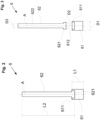
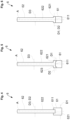
- FIG. 2 shows a schematic sectional view of an embodiment of the piston rod 6, which is the same design that is also shown in 1 is shown.
- 3 shows 3 the embodiment 2 again, but with the lower part 61 shown separated from the upper part 62.
- the lower part 61 is designed essentially in the form of a circular cylinder and has an upper end 611 with which the lower part 61 adjoins the upper part 62 .
- the upper part 62 comprises a circular-cylindrical rod 622 and a lower end 621 which adjoins the rod 622 at the end face of the rod 622 facing the lower part 61 .
- the upper part 62 adjoins the lower part 61 with the lower end 621 .
- the lower end 621 of the upper part 62 is also designed in the shape of a circular cylinder and has an outer diameter D2 which is larger than the outer diameter D3 of the rod 622 of the upper part 62, so that the lower end 621 is designed as a kind of foot of the upper part 62.
- the upper end 611 of the lower part 61 of the piston rod 6 has an outer diameter D1 which is larger than the outer diameter D2 of the lower end 621 of the upper part 62.
- the upper end 611 of the lower part 61 has a centrally located recess 612 configured to receive the lower end 621 of the upper part 62 .
- the inner diameter of the recess 612 preferably corresponds to the outer diameter D2 of the lower end 621 of the upper part 62, except for a necessary fit, for example a clearance fit or a transition fit.
- the upper end 611 of the lower part 61 encloses the lower end 621 of the upper part 62.
- the lower end 621 of the upper part 62 has a centrally located receptacle 623 which is configured in such a way that it can receive the upper end 611 of the lower part 61 .
- the upper end 611 of the lower part 61 has the outer diameter D1 which is smaller than the outer diameter of the rest of the lower part 61 such that the upper end 611 forms a projection.
- the inner diameter of the receptacle 623 preferably corresponds to the outer diameter D1 of the upper end 611 of the lower part 61, except for a necessary fit, for example a clearance fit or a transition fit.
- the lower end 621 of the upper part 62 encloses the upper end 611 of the lower part 61.
- the outer diameter D2 of the lower end 621 of the upper part 62 is larger than the outer diameter D3 of the rod 622 of the upper part 62 and equal to the outer diameter D1 of the upper end 611 of the lower part 61 of the piston rod 6.
- the outer diameter D2 of the lower end 621 of the upper part 62 is the same size as the outer diameter D3 of the rod 622 of the upper part 62 and smaller than the outer diameter D1 of the upper end 611 of the lower part 61 of the piston rod 6.
- the outside diameter D2 of the lower end 621 of the upper part 62 is the same as the outside diameter D3 of the rod 622 of the upper part 62 and the same size as the outside diameter D1 of the upper end 611 of the lower part 61 of the piston rod 6.
- the outer diameter D2 of the lower end 621 of the upper part 62 is the same size as the outer diameter D3 of the rod 622 of the upper part 62 and larger than the outer diameter D1 of the upper end 611 of the lower part 61 of the piston rod 6.
Landscapes
- Engineering & Computer Science (AREA)
- Chemical & Material Sciences (AREA)
- Combustion & Propulsion (AREA)
- Mechanical Engineering (AREA)
- General Engineering & Computer Science (AREA)
- Oil, Petroleum & Natural Gas (AREA)
- Output Control And Ontrol Of Special Type Engine (AREA)
Abstract
Es wird ein Grossdieselmotor vorgeschlagen mit mindestens einem Zylinder (2), welcher einen Brennraum (4) aufweist, der durch einen Kolben (3) begrenzt wird, welcher entlang einer Zylinderachse (A) hin- und herbewegbar angeordnet ist, sowie mit einer rotierbaren Kurbelwelle (9), wobei der Kolben (3) über eine Kolbenstange (6) mit einem Kreuzkopf (7) verbunden ist, der einen Kreuzkopfzapfen (71) aufweist, wobei der Kreuzkopf (7) über eine Schubstange (8) mit der Kurbelwelle (9) verbunden ist, wobei die Kolbenstange (6) in dem Kreuzkopfzapfen (71) angeordnet ist, und wobei eine Kontrollvorrichtung (10) zum Einstellen eines Kompressionsverhältnisse vorgesehen ist, mit welcher die Kolbenstange (6) relativ zum Kreuzkopfzapfen (71) in Richtung der Zylinderachse (A) verschiebbar ist. Die Kolbenstange (6) umfasst ein unteres Teil (61) und ein oberes Teil (62), wobei das untere Teil (61) im Kreuzkopfzapfen (71) angeordnet ist, wobei das obere Teil (62) den Kolben (3) mit dem unteren Teil (61) verbindet, und wobei das untere Teil (61) und das obere Teil (62) lösbar miteinander verbunden sind.A large diesel engine has at least one cylinder (2) which has a combustion chamber (4) delimited by a piston (3) which can be moved back and forth along a cylinder axis (A), and a rotatable crankshaft (9), the piston (3) being connected via a piston rod (6) to a crosshead (7) which has a crosshead pin (71), the crosshead (7) being connected to the crankshaft (9 ) is connected, wherein the piston rod (6) is arranged in the crosshead pin (71), and wherein a control device (10) is provided for setting a compression ratio, with which the piston rod (6) relative to the crosshead pin (71) in the direction of the cylinder axis (A) is movable. The piston rod (6) comprises a lower part (61) and an upper part (62), the lower part (61) being arranged in the crosshead pin (71), the upper part (62) supporting the piston (3) with the lower Part (61) connects, and wherein the lower part (61) and the upper part (62) are releasably connected to each other.
Description
Die Erfindung betrifft einen Grossdieselmotor gemäss dem Oberbegriff des unabhängigen Patentanspruchs.The invention relates to a large diesel engine according to the preamble of the independent patent claim.
Grossdieselmotoren werden klassischerweise mit Schweröl betrieben. Grossdieselmotoren, die als Zweitakt- oder als Viertakt-Maschinen ausgestaltet sein können, beispielsweise als längsgespülte Zweitakt-Grossdieselmotoren, werden häufig als Antriebsaggregate für Schiffe oder auch im stationären Betrieb, z.B. zum Antrieb grosser Generatoren zur Erzeugung elektrischer Energie eingesetzt. Dabei laufen die Motoren in der Regel über beträchtliche Zeiträume im Dauerbetrieb, was hohe Anforderungen an die Betriebssicherheit und die Verfügbarkeit stellt. Daher sind für den Betreiber insbesondere lange Wartungsintervalle, geringer Verschleiss und ein wirtschaftlicher Umgang mit den Betriebsstoffen zentrale Kriterien. Grossdieselmotoren haben typischerweise Zylinder, deren Innendurchmesser (Bohrung) mindestens 200 mm beträgt. Heutzutage werden Grossdieselmotoren mit einer Bohrung von bis zu 960 mm oder sogar noch mehr eingesetzt.Large diesel engines are traditionally operated with heavy fuel oil. Large diesel engines, which can be designed as two-stroke or four-stroke machines, for example as longitudinally scavenged two-stroke large diesel engines, are often used as drive units for ships or in stationary operation, e.g. to drive large generators to generate electrical energy. The motors usually run continuously for considerable periods of time, which places high demands on operational reliability and availability. Long maintenance intervals, low wear and economical use of operating materials are therefore key criteria for the operator. Large diesel engines typically have cylinders with an inside diameter (bore) of at least 200 mm. Nowadays large diesel engines with a bore of up to 960 mm or even more are used.
Unter den Aspekten des wirtschaftlichen und effizienten Betriebs, der Einhaltung von Abgasgrenzwerten und der Verfügbarkeit von Ressourcen sucht man heute auch bei Grossdieselmotoren nach Alternativen zu dem Brennstoff Schweröl. Dabei werden sowohl flüssige Brennstoffe eingesetzt, also Brennstoffe, die im flüssigen Zustand in den Brennraum eingebracht werden, als auch gasförmige Brennstoffe, also Brennstoffe, die im gasförmigen Zustand in den Brennraum eingebracht werden.With regard to economic and efficient operation, compliance with emission limit values and the availability of resources, alternatives to heavy fuel oil are also being sought for large diesel engines today. Both liquid fuels are used, ie fuels that are introduced into the combustion chamber in a liquid state as well as gaseous fuels, i.e. fuels that are introduced into the combustion chamber in a gaseous state.
Beispiele für flüssige Brennstoffe als bekannte Alternativen zum Schweröl sind andere schwere Kohlenwasserstoffe, die insbesondere als Rückstände bei der Raffinerie von Erdöl übrig bleiben, Alkohole, insbesondere Methanol oder Ethanol, Benzin, Diesel, oder auch Emulsionen oder Suspensionen. So ist es z. B. bekannt, die als MSAR (Multiphase Superfine Atomised Residue) bezeichneten Emulsionen als Brennstoff zu verwenden. Eine bekannte Suspension ist diejenige aus Kohlenstaub und Wasser, die ebenfalls als Brennstoff für Grossmotoren eingesetzt wird. Als gasförmige Brennstoffe sind beispielsweise Erdgase wie LNG (liquefied natural gas), Flüssiggase wie LPG (liquefied petroleum gas) oder Ethan bekannt.Examples of liquid fuels as known alternatives to heavy oil are other heavy hydrocarbons, which remain in particular as residues in petroleum refineries, alcohols, in particular methanol or ethanol, petrol, diesel, or else emulsions or suspensions. It is e.g. For example, it is known to use emulsions referred to as MSAR (Multiphase Superfine Atomized Residue) as fuel. A well-known suspension is that of coal dust and water, which is also used as a fuel for large engines. Natural gases such as LNG (liquefied natural gas), liquid gases such as LPG (liquefied petroleum gas) or ethane are known as gaseous fuels.
Es sind insbesondere auch solche Grossdieselmotoren bekannt, die mit mindestens zwei verschiedenen Brennstoffen betreibbar sind, wobei der Motor je nach Betriebssituation oder Umgebung entweder mit dem einen Brennstoff oder mit dem anderen Brennstoff betrieben wird.In particular, such large diesel engines are also known which can be operated with at least two different fuels, the engine being operated with either one fuel or the other fuel, depending on the operating situation or the environment.
Ein Beispiel für einen Grossdieselmotor, der mit zwei unterschiedlichen Brennstoffen betreibbar ist, ist ein Grossdieselmotor, der als Dual-Fuel Grossdieselmotor ausgestaltet ist. Dieser ist in einem Flüssigmodus betreibbar, in welchem ein flüssiger Brennstoff zur Verbrennung in den Zylinder eingebracht wird, sowie in einem Gasmodus, in welchem ein Gas als Brennstoff in den Zylinder eingebracht wird.An example of a large diesel engine that can be operated with two different fuels is a large diesel engine that is designed as a dual-fuel large diesel engine. This is operable in a liquid mode in which a liquid fuel is introduced into the cylinder for combustion, and in a gas mode in which a gas is introduced into the cylinder as fuel.
Grossdieselmotoren, die mit mindestens zwei oder auch mehr verschiedenen flüssigen oder gasförmigen Brennstoffen betrieben werden können, werden häufig, je nach aktuell verwendetem Brennstoff in unterschiedlichen Betriebsmodi betrieben. In dem häufig als Dieselbetrieb bezeichneten Betriebsmodus erfolgt die Verbrennung des Brennstoffs in der Regel nach dem Prinzip der Kompressionszündung oder Selbstzündung des Brennstoffs. In dem häufig als Ottobetrieb bezeichneten Modus erfolgt die Verbrennung durch die Fremdzündung eines zündfähigen vorgemischten Luft-Brennstoff-Gemisches. Diese Fremdzündung kann beispielsweise durch einen elektrischen Funken erfolgen, z. B. mit einer Zündkerze, oder auch durch die Selbstzündung einer kleinen eingespritzten Brennstoffmenge, welche dann die Fremdzündung eines anderen Brennstoffs bewirkt. Häufig wird dabei die für die Selbstzündung vorgesehene kleine Brennstoffmenge in eine mit dem Brennraum verbundene Vorkammer eingespritzt.Large diesel engines that can be operated with at least two or more different liquid or gaseous fuels are often operated in different operating modes, depending on the fuel currently being used. In the operating mode, which is often referred to as diesel operation, the fuel is usually burned according to the principle of compression ignition or self-ignition of the fuel. Combustion takes place in what is often referred to as Otto mode by the external ignition of an ignitable premixed air-fuel mixture. This external ignition can be done for example by an electric spark, z. B. with a spark plug, or by self-ignition of a small amount of injected fuel, which then causes the external ignition of another fuel. The small amount of fuel intended for self-ignition is often injected into an antechamber connected to the combustion chamber.
Ferner sind auch Mischformen aus dem Ottobetrieb und dem Dieselbetrieb bekannt.Mixed forms from Otto operation and diesel operation are also known.
Im Rahmen dieser Anmeldung sind mit dem Begriff "Grossdieselmotor" solche Motoren gemeint, die zumindest in einem Dieselbetrieb betrieben werden können. Insbesondere umfasst der Begriff "Grossdieselmotor" also auch solche Dual-Fuel Grossmotoren, die ausser im Dieselbetrieb auch noch in einem anderen Betrieb, beispielsweise dem Otto-Betrieb, betreibbar sind.In the context of this application, the term “large diesel engine” refers to engines that can be operated at least in diesel mode. In particular, the term "large diesel engine" also includes such large dual-fuel engines that can be operated in another mode, for example Otto mode, in addition to diesel mode.
Im Rahmen dieser Anmeldung ist mit dem Begriff "Gasmodus" bzw. "Betrieb im Gasmodus" gemeint, dass nur das Gas bzw. der gasförmiger Brennstoff für die drehmomenterzeugende Verbrennung als Brennstoff genutzt wird. Zwar ist es, wie bereits erwähnt, möglich und durchaus auch üblich, dass im Gasmodus für die Fremdzündung des vorgemischten Luft-Brennstoff-Gemisches eine geringe Menge eines selbstzündenden flüssigen Brennstoffs, z. B. Schweröl, eingespritzt wird, um die Fremdzündung auszuführen, aber dennoch wird der Verbrennungsprozess, welcher das Drehmoment erzeugt, vollständig mit dem Gas bzw. mit dem gasförmigen Brennstoff betrieben.In the context of this application, the term "gas mode" or "operation in gas mode" means that only the gas or gaseous fuel for the torque-generating combustion is used as fuel. Although it is, as already mentioned, possible and quite common that in the gas mode for the spark ignition of the premixed air-fuel mixture, a small amount of a self-igniting liquid fuel such. B. heavy oil, is injected to perform the spark ignition, but still the combustion process that produces the torque is entirely gas or gaseous fuel driven.
Dieser Vorgang der Fremdzündung durch Selbstzündung einer geringen Menge eines flüssigen Brennstoffs wird manchmal auch als Piloteinspritzung bezeichnet. Diese Piloteinspritzung hat nichts zu tun mit der Einspritzung des flüssigen Brennstoffs in den Brennraum, wenn der Grossmotor im Flüssigmodus betrieben wird. Für die Piloteinspritzung wird üblicherweise eine andere Einspritzvorrichtung genutzt als für das Einspritzen des flüssigen Brennstoffs im Flüssigmodus. Häufig wird zudem bei der Piloteinspritzung die geringe Menge des flüssigen Brennstoffs auch nicht direkt in den Brennraum eingespritzt, sondern in mindestens eine Vorkammer, die über einen Kanal mit dem Brennraum verbunden ist.This spark ignition process by self-igniting a small amount of liquid fuel is sometimes referred to as pilot injection. This pilot injection has nothing to do with the injection of liquid fuel into the combustion chamber when the large engine is operated in liquid mode. A different injection device is usually used for the pilot injection than for injecting the liquid fuel in liquid mode. In addition, with pilot injection, the small amount of liquid fuel is often not injected directly into the combustion chamber, but rather into at least one antechamber, which is connected to the combustion chamber via a duct.
Auch ist es bekannt, einen solchen Dual-Fuel Grossdieselmotor im Gasmodus mit einem Niederdruckverfahren zu betreiben, d.h. das Gas wird im gasförmigen Zustand in den Zylinder eingebracht, wobei der Einspritzdruck des Gases höchstens 50 bar vorzugsweise höchstens 20 bar beträgt. Dazu ist in der Zylinderwandung mindestens eine Gaseinlassöffnung vorgesehen, durch welche im Gasmodus das Gas in den Zylinder eingebracht wird. In der Praxis sind häufig zwei Gaseinlassöffnungen vorgesehen, die sich bezüglich der Zylinderachse diametral gegenüberliegen. Die Gaseinlassöffnung(en) sind dabei auf einer solchen Höhe zwischen dem unteren Umkehrpunkt und dem oberen Umkehrpunkt der Kolbenbewegung angeordnet, dass das Gas bei der Aufwärtsbewegung des Kolbens in den Zylinder eingebracht werden kann, solange noch keine oder zumindest keine wesentliche Kompression im Zylinder erfolgt ist.It is also known to operate such a dual-fuel large diesel engine in gas mode using a low-pressure process, i.e. the gas is introduced into the cylinder in the gaseous state, with the injection pressure of the gas being at most 50 bar, preferably at most 20 bar. For this purpose, at least one gas inlet opening is provided in the cylinder wall, through which the gas is introduced into the cylinder in gas mode. In practice, two gas inlet openings are often provided, which are diametrically opposed with respect to the cylinder axis. The gas inlet opening(s) are arranged at such a height between the lower reversal point and the upper reversal point of the piston movement that the gas can be introduced into the cylinder during the upward movement of the piston as long as no or at least no significant compression has taken place in the cylinder .
Üblicherweise werden Grossdieselmotoren so ausgelegt, dass das Verdichtungsverhältnis bzw. das Kompressionsverhältnis am 100% Lastpunkt, also bei Volllast optimiert ist und der Grossdieselmotor dort einen möglichst guten Kompromiss zwischen dem Verbrennungsverhalten und dem Wirkungsgrad aufweist, das heisst, die Grossdieselmotoren sind so ausgelegt, dass sie am 100% Lastpunkt, also bei Volllast und maximaler Geschwindigkeit den höchst möglichen thermodynamischen Wirkungsgrad haben.Large diesel engines are usually designed in such a way that the compression ratio is optimized at the 100% load point, i.e. at full load, and the large diesel engine has the best possible compromise between combustion behavior and efficiency there, i.e. the large diesel engines are designed in such a way that they have the highest possible thermodynamic efficiency at the 100% load point, i.e. at full load and maximum speed.
Das Kompressionsverhältnis ist eine geometrische Grösse, welche das Verhältnis eines ersten Volumens des Brennraumes vor dem Verdichten des Luft-Brennstoffgemisches zu einem verbliebenen zweiten Volumen des Brennraumes nach dem Verdichten des Luft-Brennstoffgemisches ist.The compression ratio is a geometric variable which is the ratio of a first volume of the combustion chamber before the compression of the air-fuel mixture to a remaining second volume of the combustion chamber after compression of the air-fuel mixture.
Die Optimierung des Brennverhaltens am 100% Lastpunkt hat zur Folge, dass in tieferen Lastbereichen, also beispielsweise bei einem tieferen Mitteldruck, der Wirkungsgrad des Grossdieselmotors nicht mehr optimal ist.The optimization of the combustion behavior at the 100% load point means that the efficiency of the large diesel engine is no longer optimal in lower load ranges, for example at a lower mean pressure.
Ferner ist es bei Grossdieselmotoren, die mit mindestens zwei unterschiedlichen Brennstoffen betrieben werden -also beispielsweise Dual-Fuel Grossdieselmotoren- wünschenswert, für jeden der unterschiedlichen Brennstoffe einen möglichst hohen Wirkungsgrad zu erzielen.Furthermore, in the case of large diesel engines that are operated with at least two different fuels—that is to say, for example, dual-fuel large diesel engines—it is desirable to achieve the highest possible degree of efficiency for each of the different fuels.
Aus diesen Gründen sind Grossdieselmotoren bekannt, bei denen das Kompressionsverhältnis verändert werden kann, um dadurch den Wirkungsgrad für die jeweilige Last und/oder für den jeweiligen Brennstoff zu optimieren. Derartige Ausgestaltungen werden auch als VCR-System bezeichnet (VCR: Variable Compression Ratio)For these reasons, large diesel engines are known in which the compression ratio can be changed in order to thereby optimize the efficiency for the respective load and/or for the respective fuel. Such configurations are also referred to as VCR systems (VCR: Variable Compression Ratio)
Für einen Grossdieselmotor mit Kreuzkopfantrieb ist es beispielsweise aus der
Ausgehend von diesem Stand der Technik ist es eine Aufgabe der Erfindung, einen Grossdieselmotor mit Kreuzkopfantrieb vorzuschlagen, bei welchem das Kompressionsverhältnis in einfacher Weise verändert werden kann, wobei eine besonders gute und wirtschaftliche Ausgestaltung zur Änderung des Kompressionsverhältnisses vorgesehen ist.Proceeding from this state of the art, it is an object of the invention to propose a large diesel engine with a crosshead drive, in which the compression ratio can be changed in a simple manner, a particularly good and economical design for changing the compression ratio being provided.
Der diese Aufgabe lösenden Gegenstand der Erfindung ist durch die Merkmale des unabhängigen Patentanspruchs gekennzeichnet. Erfindungsgemäss wird ein Grossdieselmotor vorgeschlagen, mit mindestens einem Zylinder, welcher einen Brennraum aufweist, der durch einen Kolben begrenzt wird, welcher entlang einer Zylinderachse hin- und herbewegbar angeordnet ist, sowie mit einer rotierbaren Kurbelwelle, wobei der Kolben über eine Kolbenstange mit einem Kreuzkopf verbunden ist, der einen Kreuzkopfzapfen aufweist, wobei der Kreuzkopf über eine Schubstange mit der Kurbelwelle verbunden ist, wobei die Kolbenstange in dem Kreuzkopfzapfen angeordnet ist, und wobei eine Kontrollvorrichtung zum Einstellen eines Kompressionsverhältnisse vorgesehen ist, mit welcher die Kolbenstange relativ zum Kreuzkopfzapfen in Richtung der Zylinderachse verschiebbar ist. Die Kolbenstange umfasst ein unteres Teil und ein oberes Teil, wobei das untere Teil im Kreuzkopfzapfen angeordnet ist, wobei das obere Teil den Kolben mit dem unteren Teil verbindet, und wobei das untere Teil und das obere Teil lösbar miteinander verbunden sind.The object of the invention that solves this problem is characterized by the features of the independent patent claim. According to the invention, a large diesel engine is proposed, with at least one cylinder, which has a combustion chamber that is delimited by a piston, which is arranged such that it can be moved back and forth along a cylinder axis, and with a rotatable crankshaft, the piston being connected to a crosshead via a piston rod which has a crosshead journal, the crosshead being connected to the crankshaft via a connecting rod, the piston rod being arranged in the crosshead journal, and a control device being provided for setting a compression ratio, with which the piston rod is moved relative to the crosshead journal in the direction of the cylinder axis is movable. The piston rod comprises a lower part and an upper part, the lower part being arranged in the crosshead pin, the upper part connecting the piston to the lower part, and the lower part and the upper part being detachably connected to each other.
Diese Ausgestaltung der Kolbenstange mit einem unteren Teil und mit einem oberen Teil stellt eine besonders vorteilhafte und wirtschaftliche Ausführungsform dar, mit welcher das Kompressionsverhältnis im Zylinder veränderbar ist.This configuration of the piston rod with a lower part and with an upper part represents a particularly advantageous and economical embodiment with which the compression ratio in the cylinder can be changed.
So kann beispielsweise das untere Teil der Kolbenstange, welches in dem Kreuzkopfzapfen angeordnet ist und im Betrieb sehr hohen Belastungen ausgesetzt ist, aus einem höherwertigen Material und/oder mit einer höheren Präzision gefertigt werden, als das obere Teil der Kolbenstange, welches aus einem kostengünstigeren Material und/oder mit geringeren Anforderungen an die Präzision gefertigt werden kann.For example, the lower part of the piston rod, which is arranged in the crosshead pin and is exposed to very high loads during operation, can be manufactured from a higher-quality material and/or with greater precision than the upper part of the piston rod, which is made from a less expensive material and/or can be manufactured with lower precision requirements.
Die Ausgestaltung hat auch im Hinblick auf Instandhaltungs- oder Servicearbeiten Vorteile. Sollen beispielsweise im Rahmen von Wartungsarbeiten der Kolben und die Kolbenstange aus dem Zylinder entfernt werden, so kann bei der erfindungsgemässen Ausgestaltung das untere Teil der Kolbenstange im Kreuzkopfzapfen verbleiben, während der Kolben zusammen mit dem oberen teil der Kolbenstange aus dem Zylinder herausgezogen wird. Somit ist das untere Teil, das im Kreuzkopf verbleibt wesentlich besser geschützt.The configuration also has advantages with regard to maintenance or service work. If, for example, the piston and the piston rod are to be removed from the cylinder as part of maintenance work, the lower part of the piston rod can remain in the crosshead pin in the configuration according to the invention, while the piston together with the upper part of the piston rod are removed from the cylinder is pulled out. Thus, the lower part, which remains in the crosshead, is much better protected.
Auch im Hinblick auf die Herstellung ist die Ausgestaltung der Kolbenstange mit dem unteren und dem oberen Teil sehr vorteilhaft. Die Bearbeitung des unteren Teils ist wesentlich einfacher. So können Bohrungen im unteren Teil, die beispielsweise für das Zu- und Abführen von Kühlöl benötigt werden, das im Betriebszustand durch die Kolbenstange zum Kolben geführt wird, wesentlich einfacher, nämlich direkt von der Oberseite des unteren Teils gefertigt werden. Es ist nicht mehr notwendig, solche Fertigungen vom oberen, das heisst von dem mit dem Kolben verbundenen Ende der Kolbenstange durchzuführen.The configuration of the piston rod with the lower and the upper part is also very advantageous with regard to production. Machining the lower part is much easier. Bores in the lower part, which are required, for example, for supplying and removing cooling oil that is routed through the piston rod to the piston in the operating state, can be made much more simply, namely directly from the upper side of the lower part. It is no longer necessary to carry out such productions from the upper end, that is to say from the end of the piston rod which is connected to the piston.
Auch ist die gesamte Bearbeitung des unteren Teils deutlich einfacher, weil es von dem Rest der Kolbenstange getrennt hergestellt werden kann. Das untere Teil, welches in den Kreuzkopfzapfen des Kreuzkopfes eingepasst werden muss, verlangt üblicherweise eine deutlich höhere Präzision, die sich bei der getrennten Herstellung des unteren Teils wesentlich einfacher erreichen lässt. Auch andere Bearbeitungsschritte am unteren Teil, beispielsweise Schleifvorgänge, Oberflächenbehandlungen, z. B. eine Oberflächenhärtung, Oberflächenbeschichtungen, z.B. mit Chrom, mittels PVD (PVD: Physical Vapor Deposition), mittels Auftragsschweissen oder Wärmebehandlungen sind erheblich einfacher durchzuführen, weil das untere Teil getrennt vom Rest der Kolbenstange hergestellt und bearbeitet werden kann.Also, the overall machining of the lower part is much easier because it can be manufactured separately from the rest of the piston rod. The lower part, which must be fitted into the crosshead pin of the crosshead, usually requires a significantly higher level of precision, which can be achieved much more easily if the lower part is manufactured separately. Other processing steps on the lower part, such as grinding operations, surface treatments, e.g. B. surface hardening, surface coatings, e.g. with chrome, using PVD (PVD: Physical Vapor Deposition), using build-up welding or heat treatments are much easier to carry out because the lower part can be manufactured and machined separately from the rest of the piston rod.
Vorzugsweise ist das untere Teil der Kolbenstange als hydraulischer Kolben ausgestaltet, der eine hydraulische Kammer begrenzt, die im Kreuzkopfzapfen angeordnet ist. Die Kontrollvorrichtung zum Einstellen des Kompressionsverhältnisse ist dann als eine hydraulische Vorrichtung ausgestaltet. Durch Einbringen eines Hydraulikmediums, beispielsweise eines Öls, in die hydraulische Kammer im Kreuzkopfzapfen kann die Kolbenstange über das als hydraulischer Kolben ausgestaltete untere Teil relativ zum Kreuzkopfzapfen in Richtung der Zylinderachse verschoben werden, sodass sich das minimale Volumen des Brennraums verkleinert. Durch Ablassen des Hydraulikmediums aus der hydraulischen Kammer kann die Kolbenstange relativ zum Kreuzkopfzapfen abgesenkt werden, sodass sich das minimale Volumen des Brennraums vergrössert.Preferably, the lower part of the piston rod is designed as a hydraulic piston which delimits a hydraulic chamber which is arranged in the crosshead pin. The control device for setting the compression ratio is then designed as a hydraulic device. By introducing a hydraulic medium, for example an oil, into the hydraulic chamber in the crosshead pin, the piston rod can be moved relative to the lower part designed as a hydraulic piston Crosshead pins are shifted in the direction of the cylinder axis, so that the minimum volume of the combustion chamber is reduced. By draining the hydraulic medium from the hydraulic chamber, the piston rod can be lowered relative to the crosshead pin, so that the minimum volume of the combustion chamber is increased.
Insbesondere wenn das untere Teil der Kolbenstange als hydraulischer Kolben ausgestaltet ist, stellt es einen grossen Vorteil dar, dass das untere Teil von dem oberen Teil lösbar und somit separat herstellbar ist. Die hohe Anforderung an die präzise Ausgestaltung des hydraulischen Kolbens lässt sich damit wesentlich einfacher erzielen. Auch hier ist es ein Vorteil, dass bei Wartungsarbeiten das als hydraulischer Kolben ausgestaltete untere Teil geschützt im Kreuzkopfzapfen verbleiben kann, wenn der Rest der Kolbenstange zusammen mit dem Kolben aus dem Zylinder herausgezogen wird.In particular, when the lower part of the piston rod is designed as a hydraulic piston, it is a great advantage that the lower part can be detached from the upper part and can therefore be manufactured separately. The high requirement for the precise design of the hydraulic piston can thus be achieved much more easily. Here, too, it is an advantage that during maintenance work the lower part, which is designed as a hydraulic piston, can remain protected in the crosshead pin when the rest of the piston rod is pulled out of the cylinder together with the piston.
Besonders bevorzugt ist das untere Teil aus einem ersten Material gefertigt, und das obere Teil ist aus einem zweiten Material gefertigt, wobei das erste Material verschieden ist von dem zweiten Material. Das erste Material ist vorzugsweise ein Material mit hoher Festigkeit, das den starken mechanischen Beanspruchungen widerstehen kann, insbesondere auch dann, wenn das untere Teil mit den Bohrungen für beispielsweise Kühlöl, Schmieröl oder andere Fluide versehen ist. Das zweite Material ist vorzugsweise ein kostengünstigeres Material, beispielsweise ein Stahl, wodurch sich die Herstellungskosten reduzieren lassen. Natürlich sind auch solche Ausgestaltungen möglich bei denen das erste Material das gleiche Material ist wie das zweite Material, d.h. das untere Teil und das obere teil der Kolbenstange bestehen aus demselben Material.More preferably, the lower part is made of a first material and the upper part is made of a second material, the first material being different from the second material. The first material is preferably a material with high strength that can withstand the strong mechanical stresses, especially when the lower part is provided with the bores for example cooling oil, lubricating oil or other fluids. The second material is preferably a less expensive material, for example steel, as a result of which the production costs can be reduced. Of course, configurations are also possible in which the first material is the same material as the second material, i.e. the lower part and the upper part of the piston rod consist of the same material.
Gemäss einer bevorzugten Ausführungsform weist das untere Teil in Richtung der Zylinderachse eine erste Länge auf, und das obere Teil weist in Richtung der Zylinderachse eine zweite Länge auf, wobei die zweite Länge mindestens das Dreifache, vorzugsweise mindestens das Fünffache, der ersten Länge beträgt. Hierdurch ist es möglich, das untere Teil, das üblicherweise aus einem teureren Material besteht oder zusätzlichen Behandlungen unterzogen wird, möglichst klein zu halten, und den überwiegenden Teil der Kolbenstange kostengünstiger herzustellen.According to a preferred embodiment, the lower part has a first length in the direction of the cylinder axis, and the upper part has a second length in the direction of the cylinder axis, the second length being at least three times, preferably at least five times, the first length is. This makes it possible to keep the lower part, which usually consists of a more expensive material or is subjected to additional treatments, as small as possible, and to manufacture the major part of the piston rod more cheaply.
Vorzugsweise ist die Grenze zwischen dem unteren Teil und dem oberen Teil der Kolbenstange so angeordnet, dass sich das untere Teil der Kolbenstange während des Betriebs des Grossdieselmotors immer unterhalb einer Dichtungsanordnung befindet, welche den Durchtritt der Kolbenstange in den Zylinder dichtet. Üblicherweise ist der Durchgang der Kolbenstange in den Zylinder in einem Grossdieselmotor mittels einer Stopfbuchse abgedichtet. Dann ist die Grenze zwischen dem unteren und dem oberen Teil der Kolbenstange so angeordnet, dass diese Grenze sich nicht durch die Stopfbuchse hindurch bewegt, sondern bei der Arbeitsbewegung des Kolbens immer unterhalb der Stopfbuchse bleibt.The boundary between the lower part and the upper part of the piston rod is preferably arranged such that the lower part of the piston rod is always located below a sealing arrangement which seals the passage of the piston rod into the cylinder during operation of the large diesel engine. The passage of the piston rod into the cylinder in a large diesel engine is usually sealed by means of a stuffing box. Then the boundary between the lower and the upper part of the piston rod is arranged in such a way that this boundary does not move through the stuffing box, but always remains below the stuffing box during the working movement of the piston.
Im Folgenden werden noch einige bevorzugte Massnahmen für die Ausgestaltung des unteren Teils und des oberen Teils der Kolbenstange genannt.Some preferred measures for the design of the lower part and the upper part of the piston rod are mentioned below.
Vorzugsweise weist das untere Teil der Kolbenstange ein oberes Ende auf, welches mit einem unteren Ende des oberen Teils der Kolbenstange verbunden ist.Preferably, the lower part of the piston rod has an upper end connected to a lower end of the upper part of the piston rod.
Gemäss einer bevorzugten Ausführungsform weist das obere Ende des unteren Teils der Kolbenstange einen grösseren Aussendurchmesser auf als das untere Ende des oberen Teils der Kolbenstange.According to a preferred embodiment, the upper end of the lower part of the piston rod has a larger outside diameter than the lower end of the upper part of the piston rod.
Bei einer anderen bevorzugten Ausführungsform weist das obere Ende des unteren Teils der Kolbenstange den gleichen Aussendurchmesser auf wie das untere Ende des oberen Teils der Kolbenstange.In another preferred embodiment, the upper end of the lower part of the piston rod has the same outside diameter as the lower end of the upper part of the piston rod.
Es sind auch Ausgestaltungen möglich, bei denen das obere Ende des unteren Teils der Kolbenstange einen kleineren Aussendurchmesser aufweist als das untere Ende des oberen Teils der Kolbenstange.Configurations are also possible in which the upper end of the lower part of the piston rod has a smaller outside diameter than the lower end of the upper part of the piston rod.
Ferner ist es eine bevorzugte Ausgestaltung, dass das obere Ende des unteren Teils der Kolbenstange eine Ausnehmung aufweist, welche das untere Ende des oberen Teils der Kolbenstange aufnimmt.Furthermore, it is a preferred embodiment that the upper end of the lower part of the piston rod has a recess which accommodates the lower end of the upper part of the piston rod.
Dabei ist es speziell bevorzugt, dass das obere Ende des unteren Teils der Kolbenstange das untere Ende des oberen Teils vollständig umgibt.It is particularly preferred that the upper end of the lower part of the piston rod completely surrounds the lower end of the upper part.
Gemäss einer anderen bevorzugten Ausführungsform weist das untere Ende des oberen Teils der Kolbenstange eine Aufnahme auf, welche das obere Ende des unteren Teils der Kolbenstange aufnimmt.According to another preferred embodiment, the lower end of the upper part of the piston rod has a seat which receives the upper end of the lower part of the piston rod.
Dabei ist es speziell bevorzugt, dass das untere Ende des oberen Teils der Kolbenstange das obere Ende des unteren Teils vollständig umgibt.It is particularly preferred that the lower end of the upper part of the piston rod completely surrounds the upper end of the lower part.
Da das untere Teil der Kolbenstange im Betriebszustand des Grossdieselmotors den stärksten mechanischen Belastungen ausgesetzt ist, umfasst die Herstellung des unteren Teils vorzugsweise eine Oberflächenhärtung.Since the lower part of the piston rod is exposed to the greatest mechanical loads when the large diesel engine is in operation, the production of the lower part preferably includes surface hardening.
Vorzugsweise ist der Grossdieselmotor als längsgespülter Zweitakt-Grossdieselmotor ausgestaltet.The large diesel engine is preferably designed as a longitudinally scavenged two-stroke large diesel engine.
Besonders bevorzugt ist der Grossdieselmotor als Dual-Fuel Grossdieselmotor ausgestaltet, der in einem Flüssigmodus betreibbar ist, in welchem ein flüssiger Brennstoff zur Verbrennung in den Brennraum eingebracht wird, und der ferner in einem Gasmodus betreibbar ist, in welchem ein Gas zur Verbrennung in den Brennraum eingebracht wird.The large diesel engine is particularly preferably designed as a dual-fuel large diesel engine which can be operated in a liquid mode, in which a liquid fuel is introduced into the combustion chamber for combustion, and which can also be operated in a gas mode, in which a gas for combustion is introduced into the combustion chamber is introduced.
Weitere vorteilhafte Massnahmen und Ausgestaltungen der Erfindung ergeben sich aus den abhängigen Ansprüchen.Further advantageous measures and refinements of the invention result from the dependent claims.
Im Folgenden wird die Erfindung anhand von Ausführungsbeispielen und anhand der Zeichnung näher erläutert. In der Zeichnung zeigen:
- Fig. 1:
- eine schematische Schnittdarstellung eines Ausführungsbeispiels eines erfindungsgemässen Grossdieselmotors,
- Fig. 2:
- eine schematische Schnittdarstellung einer Ausführungsform der Kolbenstange,
- Fig. 3:
- wie
Fig. 2 , wobei jedoch das untere Teil vom oberen Teil getrennt dargestellt ist, und - Fig. 4-9:
- wie
Fig. 2 , jedoch für verschiedene Varianten für die Ausgestaltung der Kolbenstange.
- Figure 1:
- a schematic sectional view of an embodiment of a large diesel engine according to the invention,
- Figure 2:
- a schematic sectional view of an embodiment of the piston rod,
- Figure 3:
- How
2 , but with the lower part shown separated from the upper part, and - Figures 4-9:
- How
2 , but for different variants for the design of the piston rod.
Mit dem Begriff "Grossdieselmotor" sind solche Motoren gemeint, wie sie üblicherweise als Hauptantriebsaggregate für Schiffe oder auch im stationären Betrieb, z.B. zum Antrieb grosser Generatoren zur Erzeugung elektrischer Energie eingesetzt werden. Typischerweise haben die Zylinder eines Grossdieselmotors jeweils einen Innendurchmesser (Bohrung), der mindestens etwa 200 mm beträgt. Mit dem Begriff "längsgespült" ist gemeint, dass die Spül- oder Ladeluft im Bereich des unteren Endes in den Zylinder eingebracht wird. Die Verbrennungsrückstände, also insbesondere die Abgase, werden am oberen Ende des Zylinders ausgetragen.The term "large diesel engine" means such engines as are usually used as the main propulsion units for ships or in stationary operation, e.g. for driving large generators for generating electrical energy. Typically, the cylinders of a large diesel engine each have an inside diameter (bore) of at least about 200 mm. The term "longitudinally scavenged" means that the scavenging or charge air is introduced into the cylinder in the region of the lower end. The combustion residues, in particular the exhaust gases, are discharged at the upper end of the cylinder.
Bei der folgenden Beschreibung der Erfindung wird auf einen Grossdieselmotor Bezug genommen, der als Dual-Fuel Grossdieselmotor ausgestaltet ist, also als ein Motor, der mit zwei unterschiedlichen Brennstoffen betrieben werden kann. Im Speziellen kann der Dual-Fuel Grossdieselmotor in einem Flüssigmodus betrieben werden, in welchem nur ein flüssiger Brennstoff in einen Brennraum eines Zylinders eingespritzt wird. Üblicherweise wird der flüssige Brennstoff, beispielsweise Schweröl oder ein Dieselöl, zu einem geeigneten Zeitpunkt direkt in den Brennraum eingespritzt und entzündet sich dort nach dem Diesel-Prinzip der Selbstzündung. Der Grossdieselmotor kann auch in einem Gasmodus betrieben werden, bei dem ein als Brennstoff dienendes Gas, beispielsweise ein Erdgas wie LNG (Liquefied Natural Gas) oder LPG (Liquefied Petroleum Gas) oder Ethan, in Form eines vorgemischten Luft-Brennstoff-Gemisches im Brennraum durch Fremdzündung zur Verbrennung gebracht wird.In the following description of the invention, reference is made to a large diesel engine that is designed as a dual-fuel large diesel engine, ie as an engine that can be operated with two different fuels. In particular, the dual-fuel large diesel engine can be operated in a liquid mode in which only a liquid fuel is injected into a combustion chamber of a cylinder. The liquid fuel, for example heavy oil or diesel oil, is usually injected directly into the combustion chamber at a suitable time and ignites there according to the diesel principle of self-ignition. The Large diesel engines can also be operated in a gas mode in which a gas serving as a fuel, for example a natural gas such as LNG (Liquefied Natural Gas) or LPG (Liquefied Petroleum Gas) or ethane, is spark-ignited in the combustion chamber in the form of a premixed air-fuel mixture is burned.
Wie vorangehend bereits erläutert, ist der Begriff "Gasmodus" bzw. "Betrieb im Gasmodus" im Rahmen dieser Anmeldung so zu verstehen, dass der Grossdieselmotor in diesem Gasmodus nur mit Gas bzw. mit einem gasförmigen Brennstoff betrieben wird, wobei optional eine geringe Menge eines selbstzündenden Brennstoffs, z.B. Schweröl oder Dieselöl, lediglich zur Fremdzündung des Luft-Gas-Gemisches in den Brennraum oder eine Vorkammer oder mehrerer Vorkammern eingebracht wird (Piloteinspritzung).As already explained above, the term "gas mode" or "operation in gas mode" in the context of this application is to be understood in such a way that the large diesel engine is operated in this gas mode only with gas or with a gaseous fuel, with optionally a small amount of a self-igniting fuel, e.g. heavy oil or diesel oil, is only introduced into the combustion chamber or one or more pre-chambers for the purpose of external ignition of the air-gas mixture (pilot injection).
Im Speziellen arbeitet der Grossdieselmotor im Gasmodus nach einem Niederdruckverfahren, d.h. das Gas wird im gasförmigen Zustand in den Zylinder eingebracht, wobei der Einspritzdruck, mit welchem das Gas in den Zylinder eingebracht wird, höchstens 50 bar und vorzugsweise höchstens 20bar beträgt. Das Luft-Gas-Gemisch wird im Brennraum nach dem Otto-Prinzip fremdgezündet. Diese Fremdzündung wird vorzugsweise dadurch bewirkt, dass zu einem geeigneten Moment eine kleine Menge selbstzündender flüssiger Brennstoff (z. B. Diesel- oder Schweröl) in den Brennraum oder in eine Vorkammer oder in mehrere Vorkammern eingebracht wird, der sich dann selbst entzündet und dadurch die Fremdzündung des Luft-Brennstoff-Gemisches im Brennraum verursacht.In particular, the large diesel engine works in gas mode according to a low-pressure process, i.e. the gas is introduced into the cylinder in the gaseous state, with the injection pressure at which the gas is introduced into the cylinder being at most 50 bar and preferably at most 20 bar. The air-gas mixture is ignited in the combustion chamber according to the Otto principle. This spark ignition is preferably brought about by introducing a small amount of self-igniting liquid fuel (e.g. diesel or heavy oil) into the combustion chamber or into an antechamber or several antechambers at a suitable moment, which then ignites itself and thereby the spark ignition of the air-fuel mixture in the combustion chamber.
Bei dem hier beschriebenen Ausführungsbeispiel wird auf einen Grossdieselmotor Bezug genommen, der als längsgespülter Dual-Fuel Zweitakt-Grossdieselmotor mit Kreuzkopfantrieb ausgestaltet ist. Natürlich ist die Erfindung nicht auf Dual-Fuel Grossdieselmotoren beschränkt, sondern betrifft jede Art von Grossdieselmotoren, also Grossmotoren, die zumindest in einem Dieselbetrieb betrieben werden können.In the exemplary embodiment described here, reference is made to a large diesel engine which is designed as a longitudinally scavenged dual-fuel two-stroke large diesel engine with a crosshead drive. Of course, the invention is not limited to dual-fuel large diesel engines, but relates to any type of large diesel engine, ie large engines that can be operated at least in diesel mode.
Im Inneren des Zylinders 2 ist in an sich bekannter Art ein Kolben 3 angeordnet, welcher entlang einer Zylinderachse A zwischen einem unteren Umkehrpunkt und einem oberen Umkehrpunkt hin- und herbewegbar angeordnet ist.
Der Kolben 3 hat eine Oberseite 31, welche gemeinsam mit einem Zylinderdeckel 21 einen Brennraum 4 begrenzt, in welchem der Verbrennungsprozess stattfindet.The
Wie das von einem Kreuzkopfantrieb bekannt ist, ist der Koben 3 über eine Kolbenstange 6 mit einem Kreuzkopf 7 verbunden, welcher über eine Schubstange 8 mit einer Kurbelwelle 9 verbunden ist, sodass die Bewegung des Kolbens 3 über die Kolbenstange 6, den Kreuzkopf 7 und die Schubstange 8 auf die Kurbelwelle 9 übertragen wird, um diese zu drehen. Der Kreuzkopf 7 ist in an sich bekannter Weise so ausgestaltet, dass er die geradlinige Auf- und Abbewegung des Kolbens 3 und der Kolbenstange 6 in eine Rotationsbewegung der Schubstange 8 umsetzt, wobei die Schubstange 8 um einen Kreuzkopfzapfen 71 des Kreuzkopfes 7 schwenkbar gelagert ist.As is known from a crosshead drive, the
Am darstellungsgemäss unteren Ende des Zylinders 2 ist eine Dichtungsanordnung 22 vorgesehen, welche den Durchtritt der Kolbenstange 6 in den Zylinder 2 dichtet. Die Dichtungsanordnung 22 umfasst vorzugsweise eine Stopfbuchse.At the lower end of the
Der Aufbau und die einzelnen Komponenten des Grossdieselmotors 1, wie beispielsweise das Einspritzsystem für den Flüssigmodus (nicht dargestellt), das Gaszuführsystem für den Gasmodus (nicht dargestellt), das Gaswechselsystem, das Abgassystem (nicht dargestellt) oder das Turboladersystem (nicht dargestellt) für die Bereitstellung der Spül- bzw. Ladeluft, sowie das Kontroll- und Steuerungssystem (nicht dargestellt) für einen solchen Grossdieselmotor 1 sind dem Fachmann sowohl für die Ausgestaltung als Zweitaktmotor als auch für die Ausgestaltung als Viertaktmotor hinlänglich bekannt und bedürfen daher hier keiner weiteren Erläuterung.The structure and the individual components of the
Da es für das Verständnis der Erfindung ausreicht, ist von diesen Komponenten in
Das Kontroll- und Steuerungssystem ist in modernen Grossdieselmotoren ein elektronisches System, mit welchem sich üblicherweise alle Motor- oder Zylinderfunktionen, insbesondere die Einspritzung (Beginn und Ende der Einspritzung) sowohl im Gasmodus als auch im Flüssigmodus, und die Betätigung des Auslassventils 5 einstellen oder steuern bzw. regeln lassen.In modern large diesel engines, the monitoring and control system is an electronic system with which all engine or cylinder functions, in particular the injection (start and end of injection) both in gas mode and in liquid mode, and the actuation of the
Bei dem hier beschriebenen Ausführungsbeispiel eines längsgespülten Zweitakt-Grossdieselmotors sind üblicherweise im unteren Bereich eines jeden Zylinders 2 bzw. Zylinderliners Spülluftschlitze (nicht dargestellt) vorgesehen, die durch die Bewegung des Kolbens 3 im Zylinder 2 periodisch verschlossen und geöffnet werden, sodass die von einem Turbolader unter einem Ladeluftdruck in einem Einlassreceiver (nicht dargestellt) bereitgestellte Spülluft durch die Spülluftschlitze in den Zylinder 2 einströmen kann, solange diese geöffnet sind. Im Zylinderkopf bzw. im Zylinderdeckel 21 ist das meistens zentral angeordnete Auslassventil 5 vorgesehen, durch welches die Verbrennungsgase nach dem Verbrennungsprozess aus dem Zylinder 2 in das Abgassystem (nicht dargestellt) ausgetragen werden können. Das Abgassystem leitet zumindest einen Teil der Verbrennungsgase zu einer Turbine (nicht dargestellt) des Turboladers, dessen Kompressor die Ladeluft im Einlassreceiver unter dem Ladeluftdruck bereitstellt.In the embodiment of a longitudinally scavenged large two-stroke diesel engine described here, scavenging air slots (not shown) are usually provided in the lower area of each
Für das Einbringen des flüssigen Brennstoffs in den Brennraum 4 des Zylinders 2 im Flüssigmodus sind ein oder mehrere Brennstoffeinspritzdüsen vorgesehen (nicht dargestellt), die beispielsweise im Zylinderdeckel 21 in der Nähe des Auslassventils 5 angeordnet sind. Als flüssiger Brennstoff kann im Flüssigmodus beispielsweise Schweröl oder ein Dieselöl verbrannt werden.One or more fuel injection nozzles (not shown) are provided for introducing the liquid fuel into the
Für die Gaszuführung bzw. das Einbringen des Gases im Gasmodus ist ein an sich bekanntes Gaszuführsystem vorgesehen, welches die Gaseinlassöffnungen (nicht dargestellt) umfasst. Die Gaseinlassöffnungen sind vorzugsweise jeweils als Gaseinlassventil mit einer Gaseinlassdüse ausgestaltet.For the gas supply or the introduction of the gas in the gas mode, a gas supply system known per se is provided, which comprises the gas inlet openings (not shown). The gas inlet openings are preferably each designed as a gas inlet valve with a gas inlet nozzle.
Die Kolbenstange 6 ist mit ihrem darstellungsgemäss unteren Ende in dem Kreuzkopfzapfen 71 angeordnet. Ferner ist eine Kontrollvorrichtung 10 zum Einstellen eines Kompressionsverhältnisses vorgesehen. Das Kompressionsverhältnis ist eine geometrische Grösse, welche das Verhältnis eines ersten Volumens des Brennraumes 4 vor dem Verdichten der Spülluft bzw. des Luft-Brennstoffgemisches zu einem verbliebenen zweiten Volumen des Brennraumes 4 nach dem Verdichten der Spülluft bzw. des Luft-Brennstoffgemisches ist. Das erste Volumen ist das Volumen des Brennraums 4 unmittelbar nach dem Schliessen des Auslassventils 5, also zu dem Zeitpunkt, wenn bei der Aufwärtsbewegung des Kolbens 3 die Kompression beginnt. Das zweite Volumen ist das Volumen des Brennraums 4 bei maximaler Kompression der Spülluft bzw. des Luft-Brennstoffgemisches. Dies ist im Wesentlichen das Volumen des Brennraums 4 beim Beginn des Verbrennungsprozesses.The
Kontrollvorrichtungen 10 zum Ändern des Kompressionsverhältnisses sind aus dem Stand der Technik bekannt, beispielsweise aus der bereits erwähnten
Bei dem erfindungsgemässen Grossdieselmotor 1 ist die Kontrollvorrichtung 10 zum Einstellen des Kompressionsverhältnisses derart ausgestaltet, dass die im Kreuzkopfzapfen 71 angeordnete Kolbenstange 6 gesamthaft relativ zum Kreuzkopfzapfen 71 in Richtung der Zylinderachse A verschiebbar ist. Gemäss der Darstellung in
Dadurch ist es möglich, das Kompressionsverhältnis für jede Last, mit welcher der Grossdieselmotor 1 betrieben wird, optimal einzustellen, sodass für jede Last ein möglichst effizienter Verbrennungsprozess stattfindet. Ferner ist es für Dual-Fuel Grossdieselmotoren zusätzlich möglich, das Kompressionsverhältnis für den jeweiligen Brennstoff jeweils optimal einzustellen. Beispielsweise kann der Grossdieselmotor 1 im Gasmodus mit einem niedrigeren Kompressionsverhältnis betrieben werden als im Flüssigmodus.This makes it possible to optimally set the compression ratio for each load with which the
Zudem ist es möglich, das Kompressionsverhältnis auch in Abhängigkeit von anderen Betriebsbedingungen oder Betriebsparametern optimal einzustellen, beispielsweise in Abhängigkeit von der Temperatur der Spülluft (Ladeluft), der Methanzahl des Gases, das im Gasmodus als Brennstoff dient, oder in Abhängigkeit von anderen Betriebsparametern.It is also possible to set the compression ratio optimally as a function of other operating conditions or operating parameters, for example as a function of the temperature of the scavenging air (charge air), the methane number of the gas that is used as fuel in gas mode, or as a function of other operating parameters.
Erfindungsgemäss umfasst die Kolbenstange ein unteres Teil 61 und ein oberes Teil 62, wobei das untere Teil 61 im Kreuzkopfzapfen 71 angeordnet ist, und das obere Teil 62 den Kolben 3 mit dem unteren Teil 61 verbindet. Das untere Teil 61 und das obere Teil 62 der Kolbenstange 6 sind lösbar miteinander verbunden, vorzugsweise mittels einer Mehrzahl von Bolzen (nicht dargestellt), welche eine Schraubverbindung zwischen dem oberen Teil 61 und dem unteren Teil 62 realisieren, sodass das obere Teil 61 und das untere Teil 62 fest, aber lösbar miteinander verbunden sind. Dazu kann jeder Bolzen jeweils in ein Gewinde eingreifen, welche im unteren Teil 61 oder im oberen Teil 62 vorgesehen ist.According to the invention, the piston rod comprises a
Gemäss einer besonders bevorzugten Ausgestaltung ist das untere Teil 61 der Kolbenstange 6 als hydraulischer Kolben ausgestaltet, welcher eine hydraulische Kammer 11 der Kontrollvorrichtung 10 begrenzt. Die hydraulische Kammer 11 ist im Kreuzkopfzapfen 71 vorgesehen. Ferner sind nicht dargestellte Zu- und Abführleitungen mit Ventilen oder Absperrvorrichtungen vorgesehen, durch welch ein Hydraulikmedium, beispielsweise ein Öl, in die hydraulische Kammer 11 einbringbar bzw. aus der hydraulischen Kammer 11 abführbar ist.According to a particularly preferred embodiment, the
Soll beispielsweise das Kompressionsverhältnis vergrössert werden, so wird Hydraulikmedium in die hydraulische Kammer 11 eingebracht, um den Druck in der hydraulischen Kammer 11 zu erhöhen. Durch diese Druckerhöhung in der hydraulischen Kammer 11 wirkt eine darstellungsgemäss nach oben gerichtete Kraft auf das als hydraulischer Kolben ausgestaltete untere Teil 61 der Kolbenstange 6, wodurch die Kolbenstange 6 und der mit ihr fest verbundene Kolben 3 nach oben bewegt werden.For example, if the compression ratio is to be increased, hydraulic medium is introduced into the
Soll das Kompressionsverhältnis verkleinert werden, so wird Hydraulikmedium aus der hydraulischen Kammer 11 abgelassen, um den Druck in der hydraulischen Kammer 11 zu reduzieren. Durch diese Druckererniedrigung in der hydraulischen Kammer 11 bewegt sich die Kolbenstange aufgrund der Gewichtskraft darstellungsgemäss nach unten, wodurch sich das Kompressionsverhältnis verkleinert.If the compression ratio is to be reduced, then hydraulic medium is drained from the
Auf diese Weise kann das Kompressionsverhältnis hydraulisch und stufenlos verändert beziehungsweise eingestellt werden.In this way, the compression ratio can be changed or adjusted hydraulically and steplessly.
Die Ausgestaltung der Kolbenstange 6 mit dem unteren Teil 61 und dem oberen Teil 62, die lösbar miteinander verbunden sind, hat insbesondere den Vorteil, dass das untere Teil 61 und das obere Teil 62 jeweils separat voneinander herstellbar sind. Dadurch ist es in einfacher Weise möglich, das untere Teil 61 aus einem ersten Material zu fertigen und das obere Teil aus einem zweiten Material, welches verschieden von dem ersten Material ist.The configuration of the
So kann für das untere Teil 61, welches im Betriebszustand deutlich höheren mechanischen Belastungen ausgesetzt ist als das obere Teil 62, ein hochwertiges Material mit sehr guten mechanischen Eigenschaften, wie hohe Zugfestigkeit, grosse Härte, Elastizität usw. gewählt werden, während für das weniger belastete obere Teil 62 ein kostengünstigeres Material, beispielsweise ein Stahl, gewählt werden kann.A high-quality material with very good mechanical properties such as high tensile strength, great hardness, elasticity, etc. can be selected for the
Natürlich sind auch solche Ausgestaltungen möglich, bei denen das untere Teil 61 und das obere Teil 62 aus dem gleichen Material gefertigt sind, das heisst, das erste Material ist dann das gleiche wie das zweite Material. Auch bei solchen Ausgestaltungen ist es möglich, das untere Teil 61 mit einer höheren Präzision zu bearbeiten.Of course, configurations are also possible in which the
Auch ist es in einfacher Weise möglich, das untere Teil 61 zusätzlichen Behandlungsverfahren zu unterziehen, beispielsweise einer Oberflächenhärtung z. B. mittels Laser, oder einer Wärmebehandlung zur Verbesserung der mechanischen Eigenschaften. Ferner ist es möglich insbesondere das untere Teil 61 mit einer Oberflächenbeschichtung zu versehen, beispielsweise mit Chrom, oder mit einem PVD-Verfahren oder mit einem Auftragsschweissen.It is also easily possible to subject the
Zudem ist es wesentlich einfacher möglich, das untere Teil 61 als separate Komponente mit hoher Genauigkeit zu bearbeiten, beispielsweise zu schleifen. Dies ist insbesondere auch dann ein wesentlicher Aspekt, wenn das untere Teil 1 als hydraulischer Kolben ausgestaltet ist, der ein sehr genaues Einpassen in die hydraulische Kammer 11 verlangt.In addition, it is much easier to process the
Ferner ist es wesentlich einfacher, an dem unteren Teil 61 als separates Bauteil Bohrungen oder andere Bearbeitungen vorzunehmen. Beispielsweise können in dem unteren Teil 61 in sehr einfacher Weise Bohrungen hergestellt werden, die dem Zuführen und dem Abführen von Kühlöl in das und aus dem Innere(n) der Kolbenstange 6 dienen.Furthermore, it is much easier to drill holes or perform other processing on the
Auch für Wartungsarbeiten ist die Ausgestaltung der Kolbenstange mit dem unteren Teil 61 und dem oberen Teil 62 besonders vorteilhaft. So kann nämlich zum Herausziehen des Kolbens 3 aus dem Zylinder 2 die Verbindung zwischen dem oberen Teil 62 und dem unteren Teil 61 gelöst werden. Anschliessend kann der Kolben 3 zusammen mit dem oberen Teil 62 der Kolbenstange 6 aus dem Zylinder 2 entfernt werden, während das untere Teil 61 in dem Kreuzkopfzapfen 71 verbleibt und dort geschützt ist. Dies ist insbesondere bei der Ausgestaltung des unteren Teils 61 als hydraulischer Kolben ein sehr grosser Vorteil.The configuration of the piston rod with the
Vorzugsweise ist das untere Teil 61 der Kolbenstange 6 deutlich kürzer ausgestaltet als das obere Teil 62 der Kolbenstange 6, weil das untere Teil 61 mit dem Kreuzkopfzapfen 71 zusammenwirkt und daher üblicherweise eine höhere Präzision bei der Herstellung verlangt und/oder aus einem höherwertiges Material besteht als das obere Teil 62 der Kolbenstange 6. Das untere Teil 61 weist in Richtung der Zylinderachse A eine erste Länge L1 (
Im Folgenden werden anhand der
Das untere Teil 61 ist im wesentlichen kreiszylinderförmig ausgestaltet und weist ein oberes Ende 611 auf, mit welchem das untere Teil 61 an das obere Teil 62 angrenzt. Das obere Teil 62 umfasst eine kreiszylindrische Stange 622 und ein unteres Ende 621, das sich an der dem unteren Teil 61 zugewandten Stirnfläche der Stange 622 an die Stange 622 anschliesst. Das obere Teil 62 grenzt mit dem unteren Ende 621 an das untere Teil 61 an.The
Das untere Ende 621 des oberen Teils 62 ist ebenfalls kreiszylinderförmig ausgestaltet und weist einen Aussendurchmesser D2 auf, welcher grösser ist als der Aussendurchmesser D3 der Stange 622 des oberen Teils 62, sodass das untere Ende 621 als eine Art Fuss des oberen Teils 62 ausgestaltet ist.The
Das obere Ende 611 des unteren Teils 61 der Kolbenstange 6 weist einen Aussendurchmesser D1 auf, welcher grösser ist als der Aussendurchmesser D2 des unteren Endes 621 des oberen Teils 62.The
Das obere Ende 611 des unteren Teils 61 weist eine zentral angeordnete Ausnehmung 612 auf, welche so ausgestaltet ist, dass sie das untere Ende 621 des oberen Teils 62 aufnehmen kann. Vorzugsweise entspricht der Innendurchmesser der Ausnehmung 612 bis auf eine notwendige Passung, beispielsweise eine Spielpassung oder eine Übergangspassung, dem Aussendurchmesser D2 des unteren Endes 621 des oberen Teils 62. Bei dieser Ausgestaltung umschliesst also das obere Ende 611 des unteren Teils 61 das untere Ende 621 des oberen Teils 62.The
Die in
Bei der in
In den
Bei der in
Bei der in
Bei der in
Bei der in
Es versteht sich, dass auch noch weitere Ausgestaltungen der Kolbenstange 6 mit dem oberen Teil 62 und dem unteren Teil 61 möglich sind.It goes without saying that other configurations of the
Claims (15)
Priority Applications (4)
| Application Number | Priority Date | Filing Date | Title |
|---|---|---|---|
| EP21202858.3A EP4166766A1 (en) | 2021-10-15 | 2021-10-15 | Longitudinally flushed large-scale diesel engine |
| CN202211126069.XA CN115977788A (en) | 2021-10-15 | 2022-09-16 | Longitudinal scavenging large diesel engine |
| KR1020220122991A KR20230054268A (en) | 2021-10-15 | 2022-09-28 | A longitudinally scavenged large diesel engine |
| JP2022157774A JP2023059836A (en) | 2021-10-15 | 2022-09-30 | Longitudinally scavenging large-sized diesel engine |
Applications Claiming Priority (1)
| Application Number | Priority Date | Filing Date | Title |
|---|---|---|---|
| EP21202858.3A EP4166766A1 (en) | 2021-10-15 | 2021-10-15 | Longitudinally flushed large-scale diesel engine |
Publications (1)
| Publication Number | Publication Date |
|---|---|
| EP4166766A1 true EP4166766A1 (en) | 2023-04-19 |
Family
ID=78483114
Family Applications (1)
| Application Number | Title | Priority Date | Filing Date |
|---|---|---|---|
| EP21202858.3A Withdrawn EP4166766A1 (en) | 2021-10-15 | 2021-10-15 | Longitudinally flushed large-scale diesel engine |
Country Status (4)
| Country | Link |
|---|---|
| EP (1) | EP4166766A1 (en) |
| JP (1) | JP2023059836A (en) |
| KR (1) | KR20230054268A (en) |
| CN (1) | CN115977788A (en) |
Citations (5)
| Publication number | Priority date | Publication date | Assignee | Title |
|---|---|---|---|---|
| DE3516506A1 (en) * | 1985-05-08 | 1986-11-13 | M.A.N.- B & W Diesel GmbH, 8900 Augsburg | Multipart connecting rod for a large diesel engine |
| DE19712090C1 (en) * | 1997-03-22 | 1998-04-02 | Man B & W Diesel Gmbh | Reciprocating piston engine, especially large diesel engine |
| EP0851101B1 (en) * | 1996-12-24 | 2002-07-10 | Wärtsilä Schweiz AG | Diesel engine |
| EP2503116A1 (en) * | 2011-03-23 | 2012-09-26 | Wärtsilä Schweiz AG | Cylinder assembly and piston for a longitudinally flushed stroke piston combustion engine |
| EP2687707A2 (en) | 2012-07-17 | 2014-01-22 | Wärtsilä Schweiz AG | A large reciprocating piston combustion engine, a control apparatus and a method for controlling such an engine |
-
2021
- 2021-10-15 EP EP21202858.3A patent/EP4166766A1/en not_active Withdrawn
-
2022
- 2022-09-16 CN CN202211126069.XA patent/CN115977788A/en active Pending
- 2022-09-28 KR KR1020220122991A patent/KR20230054268A/en unknown
- 2022-09-30 JP JP2022157774A patent/JP2023059836A/en active Pending
Patent Citations (5)
| Publication number | Priority date | Publication date | Assignee | Title |
|---|---|---|---|---|
| DE3516506A1 (en) * | 1985-05-08 | 1986-11-13 | M.A.N.- B & W Diesel GmbH, 8900 Augsburg | Multipart connecting rod for a large diesel engine |
| EP0851101B1 (en) * | 1996-12-24 | 2002-07-10 | Wärtsilä Schweiz AG | Diesel engine |
| DE19712090C1 (en) * | 1997-03-22 | 1998-04-02 | Man B & W Diesel Gmbh | Reciprocating piston engine, especially large diesel engine |
| EP2503116A1 (en) * | 2011-03-23 | 2012-09-26 | Wärtsilä Schweiz AG | Cylinder assembly and piston for a longitudinally flushed stroke piston combustion engine |
| EP2687707A2 (en) | 2012-07-17 | 2014-01-22 | Wärtsilä Schweiz AG | A large reciprocating piston combustion engine, a control apparatus and a method for controlling such an engine |
Also Published As
| Publication number | Publication date |
|---|---|
| KR20230054268A (en) | 2023-04-24 |
| CN115977788A (en) | 2023-04-18 |
| JP2023059836A (en) | 2023-04-27 |
Similar Documents
| Publication | Publication Date | Title |
|---|---|---|
| DE69200519T2 (en) | Fuel injection valve and engine equipped with this. | |
| EP0546985A1 (en) | Fuel injection valve for a reciprocating internal combustion engine optionally operating on diesel oil or on a gaseous fuel | |
| DE69013283T2 (en) | High pressure fuel injection unit with control of the pressure of the chamber for the injection timing. | |
| CH681647A5 (en) | ||
| EP3574204B1 (en) | Internal combustion engine comprising a fuel injection nozzle with an additional supply of a combustion-promoting medium into the combustion chamber | |
| EP3786498A1 (en) | Shut-off valve for a double-walled line, gas supply system and large engine | |
| DE112020000519T5 (en) | COMBINED MULTI-CYLINDER HIGH PRESSURE OIL PUMP FOR A SLOW RUNNING MARINE ENGINE | |
| DE2644389A1 (en) | CHARGED ROTATING PISTON ENGINE | |
| EP3951160B1 (en) | Large diesel engine and fuel injection valve and fuel injection method for a large diesel engine | |
| DE19833692C2 (en) | Injector unit with timing plunger piston with a fixed stop | |
| DE102008038076A1 (en) | Piston for reciprocating engine e.g. petrol engine, of motor vehicle, has piston pin bearing comprising eccentric element, where axis of piston pin is eccentrically adjustable by rotational adjustment of eccentric element | |
| EP4166766A1 (en) | Longitudinally flushed large-scale diesel engine | |
| EP3798413A1 (en) | Control valve for a steam engine, steam engine comprising said control valve, and combined heat and power plant comprising the steam engine | |
| DE3012022A1 (en) | Reciprocating piston IC engine - has second combustion chamber in piston connected by restriction to cylinder combustion space | |
| EP3564642A1 (en) | Device for determining the pressure in a combustion engine of a large engine and large engine | |
| EP3147477B1 (en) | Gas feeding system and cylinder for a reciprocating piston engine, reciprocating combustion engine, and method for operating same | |
| EP3751123A1 (en) | Cylinder head for a cylinder of a large diesel engine and method for repairing a cylinder head | |
| DE19602474B4 (en) | Injection timing control device for a fuel injection pump | |
| EP3862611A1 (en) | Flange connection for connecting two double-walled pipe parts, gas supply system and large motor | |
| DE20220664U1 (en) | Engine with separate piston crown | |
| DE19527719A1 (en) | Fuel injection system | |
| EP4191046A1 (en) | Large diesel engine and method for determining the cylinder pressure in a large diesel engine | |
| DD201927A5 (en) | TWO STROKE COMBUSTION ENGINE | |
| EP4019751A1 (en) | Large diesel engine and method for operating a large diesel engine | |
| EP3372811A1 (en) | Method for operating a large diesel engine and large diesel engine |
Legal Events
| Date | Code | Title | Description |
|---|---|---|---|
| PUAI | Public reference made under article 153(3) epc to a published international application that has entered the european phase |
Free format text: ORIGINAL CODE: 0009012 |
|
| STAA | Information on the status of an ep patent application or granted ep patent |
Free format text: STATUS: THE APPLICATION HAS BEEN PUBLISHED |
|
| AK | Designated contracting states |
Kind code of ref document: A1 Designated state(s): AL AT BE BG CH CY CZ DE DK EE ES FI FR GB GR HR HU IE IS IT LI LT LU LV MC MK MT NL NO PL PT RO RS SE SI SK SM TR |
|
| STAA | Information on the status of an ep patent application or granted ep patent |
Free format text: STATUS: THE APPLICATION IS DEEMED TO BE WITHDRAWN |
|
| 18D | Application deemed to be withdrawn |
Effective date: 20231020 |