EP4166377B1 - Vehicle charging stations and methods for use in charging an electrically powered vehicle - Google Patents
Vehicle charging stations and methods for use in charging an electrically powered vehicle Download PDFInfo
- Publication number
- EP4166377B1 EP4166377B1 EP22198110.3A EP22198110A EP4166377B1 EP 4166377 B1 EP4166377 B1 EP 4166377B1 EP 22198110 A EP22198110 A EP 22198110A EP 4166377 B1 EP4166377 B1 EP 4166377B1
- Authority
- EP
- European Patent Office
- Prior art keywords
- vehicle
- charging
- user
- charging station
- electrically powered
- Prior art date
- Legal status (The legal status is an assumption and is not a legal conclusion. Google has not performed a legal analysis and makes no representation as to the accuracy of the status listed.)
- Active
Links
Images


Classifications
-
- G—PHYSICS
- G06—COMPUTING OR CALCULATING; COUNTING
- G06Q—INFORMATION AND COMMUNICATION TECHNOLOGY [ICT] SPECIALLY ADAPTED FOR ADMINISTRATIVE, COMMERCIAL, FINANCIAL, MANAGERIAL OR SUPERVISORY PURPOSES; SYSTEMS OR METHODS SPECIALLY ADAPTED FOR ADMINISTRATIVE, COMMERCIAL, FINANCIAL, MANAGERIAL OR SUPERVISORY PURPOSES, NOT OTHERWISE PROVIDED FOR
- G06Q50/00—Information and communication technology [ICT] specially adapted for implementation of business processes of specific business sectors, e.g. utilities or tourism
- G06Q50/40—Business processes related to the transportation industry
-
- B—PERFORMING OPERATIONS; TRANSPORTING
- B60—VEHICLES IN GENERAL
- B60L—PROPULSION OF ELECTRICALLY-PROPELLED VEHICLES; SUPPLYING ELECTRIC POWER FOR AUXILIARY EQUIPMENT OF ELECTRICALLY-PROPELLED VEHICLES; ELECTRODYNAMIC BRAKE SYSTEMS FOR VEHICLES IN GENERAL; MAGNETIC SUSPENSION OR LEVITATION FOR VEHICLES; MONITORING OPERATING VARIABLES OF ELECTRICALLY-PROPELLED VEHICLES; ELECTRIC SAFETY DEVICES FOR ELECTRICALLY-PROPELLED VEHICLES
- B60L50/00—Electric propulsion with power supplied within the vehicle
- B60L50/50—Electric propulsion with power supplied within the vehicle using propulsion power supplied by batteries or fuel cells
-
- B—PERFORMING OPERATIONS; TRANSPORTING
- B60—VEHICLES IN GENERAL
- B60L—PROPULSION OF ELECTRICALLY-PROPELLED VEHICLES; SUPPLYING ELECTRIC POWER FOR AUXILIARY EQUIPMENT OF ELECTRICALLY-PROPELLED VEHICLES; ELECTRODYNAMIC BRAKE SYSTEMS FOR VEHICLES IN GENERAL; MAGNETIC SUSPENSION OR LEVITATION FOR VEHICLES; MONITORING OPERATING VARIABLES OF ELECTRICALLY-PROPELLED VEHICLES; ELECTRIC SAFETY DEVICES FOR ELECTRICALLY-PROPELLED VEHICLES
- B60L53/00—Methods of charging batteries, specially adapted for electric vehicles; Charging stations or on-board charging equipment therefor; Exchange of energy storage elements in electric vehicles
- B60L53/10—Methods of charging batteries, specially adapted for electric vehicles; Charging stations or on-board charging equipment therefor; Exchange of energy storage elements in electric vehicles characterised by the energy transfer between the charging station and the vehicle
- B60L53/14—Conductive energy transfer
- B60L53/18—Cables specially adapted for charging electric vehicles
-
- B—PERFORMING OPERATIONS; TRANSPORTING
- B60—VEHICLES IN GENERAL
- B60L—PROPULSION OF ELECTRICALLY-PROPELLED VEHICLES; SUPPLYING ELECTRIC POWER FOR AUXILIARY EQUIPMENT OF ELECTRICALLY-PROPELLED VEHICLES; ELECTRODYNAMIC BRAKE SYSTEMS FOR VEHICLES IN GENERAL; MAGNETIC SUSPENSION OR LEVITATION FOR VEHICLES; MONITORING OPERATING VARIABLES OF ELECTRICALLY-PROPELLED VEHICLES; ELECTRIC SAFETY DEVICES FOR ELECTRICALLY-PROPELLED VEHICLES
- B60L53/00—Methods of charging batteries, specially adapted for electric vehicles; Charging stations or on-board charging equipment therefor; Exchange of energy storage elements in electric vehicles
- B60L53/30—Constructional details of charging stations
- B60L53/305—Communication interfaces
-
- B—PERFORMING OPERATIONS; TRANSPORTING
- B60—VEHICLES IN GENERAL
- B60L—PROPULSION OF ELECTRICALLY-PROPELLED VEHICLES; SUPPLYING ELECTRIC POWER FOR AUXILIARY EQUIPMENT OF ELECTRICALLY-PROPELLED VEHICLES; ELECTRODYNAMIC BRAKE SYSTEMS FOR VEHICLES IN GENERAL; MAGNETIC SUSPENSION OR LEVITATION FOR VEHICLES; MONITORING OPERATING VARIABLES OF ELECTRICALLY-PROPELLED VEHICLES; ELECTRIC SAFETY DEVICES FOR ELECTRICALLY-PROPELLED VEHICLES
- B60L53/00—Methods of charging batteries, specially adapted for electric vehicles; Charging stations or on-board charging equipment therefor; Exchange of energy storage elements in electric vehicles
- B60L53/60—Monitoring or controlling charging stations
- B60L53/65—Monitoring or controlling charging stations involving identification of vehicles or their battery types
-
- B—PERFORMING OPERATIONS; TRANSPORTING
- B60—VEHICLES IN GENERAL
- B60L—PROPULSION OF ELECTRICALLY-PROPELLED VEHICLES; SUPPLYING ELECTRIC POWER FOR AUXILIARY EQUIPMENT OF ELECTRICALLY-PROPELLED VEHICLES; ELECTRODYNAMIC BRAKE SYSTEMS FOR VEHICLES IN GENERAL; MAGNETIC SUSPENSION OR LEVITATION FOR VEHICLES; MONITORING OPERATING VARIABLES OF ELECTRICALLY-PROPELLED VEHICLES; ELECTRIC SAFETY DEVICES FOR ELECTRICALLY-PROPELLED VEHICLES
- B60L53/00—Methods of charging batteries, specially adapted for electric vehicles; Charging stations or on-board charging equipment therefor; Exchange of energy storage elements in electric vehicles
- B60L53/60—Monitoring or controlling charging stations
- B60L53/66—Data transfer between charging stations and vehicles
-
- B—PERFORMING OPERATIONS; TRANSPORTING
- B60—VEHICLES IN GENERAL
- B60L—PROPULSION OF ELECTRICALLY-PROPELLED VEHICLES; SUPPLYING ELECTRIC POWER FOR AUXILIARY EQUIPMENT OF ELECTRICALLY-PROPELLED VEHICLES; ELECTRODYNAMIC BRAKE SYSTEMS FOR VEHICLES IN GENERAL; MAGNETIC SUSPENSION OR LEVITATION FOR VEHICLES; MONITORING OPERATING VARIABLES OF ELECTRICALLY-PROPELLED VEHICLES; ELECTRIC SAFETY DEVICES FOR ELECTRICALLY-PROPELLED VEHICLES
- B60L2270/00—Problem solutions or means not otherwise provided for
- B60L2270/30—Preventing theft during charging
- B60L2270/36—Preventing theft during charging of vehicles
-
- Y—GENERAL TAGGING OF NEW TECHNOLOGICAL DEVELOPMENTS; GENERAL TAGGING OF CROSS-SECTIONAL TECHNOLOGIES SPANNING OVER SEVERAL SECTIONS OF THE IPC; TECHNICAL SUBJECTS COVERED BY FORMER USPC CROSS-REFERENCE ART COLLECTIONS [XRACs] AND DIGESTS
- Y02—TECHNOLOGIES OR APPLICATIONS FOR MITIGATION OR ADAPTATION AGAINST CLIMATE CHANGE
- Y02T—CLIMATE CHANGE MITIGATION TECHNOLOGIES RELATED TO TRANSPORTATION
- Y02T10/00—Road transport of goods or passengers
- Y02T10/60—Other road transportation technologies with climate change mitigation effect
- Y02T10/70—Energy storage systems for electromobility, e.g. batteries
-
- Y—GENERAL TAGGING OF NEW TECHNOLOGICAL DEVELOPMENTS; GENERAL TAGGING OF CROSS-SECTIONAL TECHNOLOGIES SPANNING OVER SEVERAL SECTIONS OF THE IPC; TECHNICAL SUBJECTS COVERED BY FORMER USPC CROSS-REFERENCE ART COLLECTIONS [XRACs] AND DIGESTS
- Y02—TECHNOLOGIES OR APPLICATIONS FOR MITIGATION OR ADAPTATION AGAINST CLIMATE CHANGE
- Y02T—CLIMATE CHANGE MITIGATION TECHNOLOGIES RELATED TO TRANSPORTATION
- Y02T10/00—Road transport of goods or passengers
- Y02T10/60—Other road transportation technologies with climate change mitigation effect
- Y02T10/7072—Electromobility specific charging systems or methods for batteries, ultracapacitors, supercapacitors or double-layer capacitors
-
- Y—GENERAL TAGGING OF NEW TECHNOLOGICAL DEVELOPMENTS; GENERAL TAGGING OF CROSS-SECTIONAL TECHNOLOGIES SPANNING OVER SEVERAL SECTIONS OF THE IPC; TECHNICAL SUBJECTS COVERED BY FORMER USPC CROSS-REFERENCE ART COLLECTIONS [XRACs] AND DIGESTS
- Y02—TECHNOLOGIES OR APPLICATIONS FOR MITIGATION OR ADAPTATION AGAINST CLIMATE CHANGE
- Y02T—CLIMATE CHANGE MITIGATION TECHNOLOGIES RELATED TO TRANSPORTATION
- Y02T90/00—Enabling technologies or technologies with a potential or indirect contribution to GHG emissions mitigation
- Y02T90/10—Technologies relating to charging of electric vehicles
- Y02T90/12—Electric charging stations
-
- Y—GENERAL TAGGING OF NEW TECHNOLOGICAL DEVELOPMENTS; GENERAL TAGGING OF CROSS-SECTIONAL TECHNOLOGIES SPANNING OVER SEVERAL SECTIONS OF THE IPC; TECHNICAL SUBJECTS COVERED BY FORMER USPC CROSS-REFERENCE ART COLLECTIONS [XRACs] AND DIGESTS
- Y02—TECHNOLOGIES OR APPLICATIONS FOR MITIGATION OR ADAPTATION AGAINST CLIMATE CHANGE
- Y02T—CLIMATE CHANGE MITIGATION TECHNOLOGIES RELATED TO TRANSPORTATION
- Y02T90/00—Enabling technologies or technologies with a potential or indirect contribution to GHG emissions mitigation
- Y02T90/10—Technologies relating to charging of electric vehicles
- Y02T90/14—Plug-in electric vehicles
-
- Y—GENERAL TAGGING OF NEW TECHNOLOGICAL DEVELOPMENTS; GENERAL TAGGING OF CROSS-SECTIONAL TECHNOLOGIES SPANNING OVER SEVERAL SECTIONS OF THE IPC; TECHNICAL SUBJECTS COVERED BY FORMER USPC CROSS-REFERENCE ART COLLECTIONS [XRACs] AND DIGESTS
- Y02—TECHNOLOGIES OR APPLICATIONS FOR MITIGATION OR ADAPTATION AGAINST CLIMATE CHANGE
- Y02T—CLIMATE CHANGE MITIGATION TECHNOLOGIES RELATED TO TRANSPORTATION
- Y02T90/00—Enabling technologies or technologies with a potential or indirect contribution to GHG emissions mitigation
- Y02T90/10—Technologies relating to charging of electric vehicles
- Y02T90/16—Information or communication technologies improving the operation of electric vehicles
- Y02T90/167—Systems integrating technologies related to power network operation and communication or information technologies for supporting the interoperability of electric or hybrid vehicles, i.e. smartgrids as interface for battery charging of electric vehicles [EV] or hybrid vehicles [HEV]
-
- Y—GENERAL TAGGING OF NEW TECHNOLOGICAL DEVELOPMENTS; GENERAL TAGGING OF CROSS-SECTIONAL TECHNOLOGIES SPANNING OVER SEVERAL SECTIONS OF THE IPC; TECHNICAL SUBJECTS COVERED BY FORMER USPC CROSS-REFERENCE ART COLLECTIONS [XRACs] AND DIGESTS
- Y04—INFORMATION OR COMMUNICATION TECHNOLOGIES HAVING AN IMPACT ON OTHER TECHNOLOGY AREAS
- Y04S—SYSTEMS INTEGRATING TECHNOLOGIES RELATED TO POWER NETWORK OPERATION, COMMUNICATION OR INFORMATION TECHNOLOGIES FOR IMPROVING THE ELECTRICAL POWER GENERATION, TRANSMISSION, DISTRIBUTION, MANAGEMENT OR USAGE, i.e. SMART GRIDS
- Y04S30/00—Systems supporting specific end-user applications in the sector of transportation
- Y04S30/10—Systems supporting the interoperability of electric or hybrid vehicles
- Y04S30/12—Remote or cooperative charging
-
- Y—GENERAL TAGGING OF NEW TECHNOLOGICAL DEVELOPMENTS; GENERAL TAGGING OF CROSS-SECTIONAL TECHNOLOGIES SPANNING OVER SEVERAL SECTIONS OF THE IPC; TECHNICAL SUBJECTS COVERED BY FORMER USPC CROSS-REFERENCE ART COLLECTIONS [XRACs] AND DIGESTS
- Y04—INFORMATION OR COMMUNICATION TECHNOLOGIES HAVING AN IMPACT ON OTHER TECHNOLOGY AREAS
- Y04S—SYSTEMS INTEGRATING TECHNOLOGIES RELATED TO POWER NETWORK OPERATION, COMMUNICATION OR INFORMATION TECHNOLOGIES FOR IMPROVING THE ELECTRICAL POWER GENERATION, TRANSMISSION, DISTRIBUTION, MANAGEMENT OR USAGE, i.e. SMART GRIDS
- Y04S30/00—Systems supporting specific end-user applications in the sector of transportation
- Y04S30/10—Systems supporting the interoperability of electric or hybrid vehicles
- Y04S30/14—Details associated with the interoperability, e.g. vehicle recognition, authentication, identification or billing
Definitions
- the subject matter disclosed herein relates generally to charging electrically powered vehicles and, more specifically, to systems and methods for use in communicating a user profile to a vehicle charging station.
- Electrically powered vehicles including electric vehicles and plug-in hybrid electric vehicles, include electric motors powered by energy storage devices, such as batteries. Because an energy storage device is depleted of energy as the motor is operated, the operator of the vehicle must recharge the energy storage device prior to using the vehicle again.
- US 2011/106329 A1 describes a charging station for charging plug-in vehicles with a user interface to control the charging station, claim 1.
- the user receives a request to charge the vehicle and may accept or decline, whereas the process ends also with a time run out.
- User interface 110 may be configured to display information to a user 112.
- user interface 110 includes a display device 114, such as a cathode ray tube (CRT), a liquid crystal display (LCD), an organic LED (OLED) display, an "electronic ink” display, and/or other device suitable to display information.
- user interface 110 includes an in-vehicle user interface, such as a display device of a navigation system and/or a media system.
- "in-vehicle” user interface includes an interface coupled, mounted and/or secured to a vehicle (e.g., a vehicle dashboard) and accessible to at least one user 112 while present within the vehicle.
- user interface 110 may include an audio output device (e.g., an audio adapter and/or a speaker, etc.).
- a user 112 may initiate and complete a charging process, without exiting vehicle 302 to attached a charging conduit or enter information to charging station 304.
- system 300 provides increased security, safety and/or convenience to user 112 over know methods and systems for charging an electrically powered vehicle.
- charging conduit 218 may be automatically connected to vehicle 202 prior to a charging process, such that even when a physical connection for energy transfer is present, user 112 may complete a charging processes without exiting vehicle 202.
- charging station 304 includes power source 308 and charging device 306 for controlling energy transfer from power source 308 to vehicle 302.
- Charging device 306 is configured to transmit, via network 324, a first electronic message to user 112 and receive, via network 324, a second electronic message from user 112.
- the first electronic message including a condition related to at least one of the charging process and vehicle 302.
- the second electronic message including a user command related to the condition.
- charging device 306 is able to promptly notify user 112 of one or more conditions.
- vehicle controller 314 may be coupled to an on-board computer of vehicle 302 to access information related to various sensors, such as tire pressure, window state, etc., and/or an alarm system of vehicle 302 to receive alarm indication.
- conditions may include, without limitation, a status of a charging process, an amount of energy transferred, a status, a charging error, or other information related to the charging process.
- the condition may include, without limitation the state of a window (i.e., open or closed), a tire pressure, oil change indicator, an unauthorized access (e.g., a break-in), a temperature, etc.
- the prompt notification of any of the conditions may permit user 112 to more quickly respond to the condition, which may increase efficiency and/or security while vehicle 302 is charging.
- user 112 may be notified via the first electronic message that one or more windows of vehicle 302 are open during inclement weather. User 112 may be able to promptly return to vehicle 302 to adjust one or more windows as dictated by weather.
- the user command of the second message may direct vehicle controller 314 to adjust (directly or through a different computing device) the state of the windows according to the weather.
- a charging process may cease based on an energy rate (dollar per watt) that exceeds a user preference.
- charging device 306 and/or vehicle controller 314 may transmit the first electronic message to user 112 indicating the current energy rate.
- user 112 may transmit the second message including a command to re-initiate charging of vehicle 302, notwithstanding the energy rater exceeding the user preference.
- various other alterations and/or changes may be implemented by a user via a user command in the second electronic message.
- user 112 may initiate a message to charging device 306 and/or controller 314, without a prior electronic message from charging device 306.
- the first and second electronic messages may include a SMS message, a voicemail message, an email message or other electronic message suitable for transmission over network 224, etc.
- the electronic messages may be received/transmitted by user 112 at a communication device 328, such as, without limitation, a cellular phone, a pager, a smartphone, a personal computer, a laptop, a tablet, a workstation, a security system, or any other device suitable to receive and/or send an electronic message.
- charging station 304 may communicate with vehicle 302 in response to the second message.
- charging station 304 may communicate to a third party in response to the second message.
- a message to a third-party may include a message to security personnel, a local authorities or police.
- a message to a third party may include a message to security personnel, a local authorities or police, indicating vandalism and/or tires of vehicle 302 have been slashed.
- Messages to one or more other third-parties related to the condition of the first message and/or a user command of the second message should be considered within the scope of the present disclosure.
- Fig. 4 illustrates method 400 according to an example of the present disclosure.
- Method 400 includes detecting 402 a vehicle charging station, retrieving 404 a user profile from a memory device in the electrically powered vehicle, and communicating 406 the user profile to the vehicle charging station, the user profile including billing information.
- Method 400 may include receiving at least one message from vehicle charging station 204 and displaying, at a display device 114, the at least one message to user 112.
- Method 400 may also include receiving a user profile from user 112 and storing the user profile in memory device 104.
- method 400 may include receiving an input to in-vehicle user interface 316 to define the user profile.
- Method 500 includes receiving 502, at in-vehicle user interface 316, at least one user input and communicating 504, via vehicle controller 314, a charging parameter to vehicle charging station 304 in response to the at least one user input.
- Method 500 may include displaying, at in-vehicle user interface 316, at least one charging option to user 112, and wherein the at least one user input selects the at least one charging option.
- Method 500 may also include displaying, at in-vehicle user interface 316, at least one message from vehicle charging station 304.
- Method 500 may include establishing a wireless connection between electrically powered vehicle 302 and vehicle charging station 304.
- Method 600 includes controlling 602, at the charging device, a charging process including energy transfer between the power source and the electrically powered vehicle, transmitting 604, via network 324, a first electronic message to user 112 and receiving 606, via network 324, a second electronic message.
- the first electronic message includes at least one condition related to at least one of the charging process and electrically power vehicle 302.
- the second electronic message includes a user command related to the at least one condition.
- Method 600 may include transmitting the user command to electrically powered vehicle 302. Method 600 may also include transmitting a third message to a third-party in response to the user command. Moreover, method 600 may include altering the charging process in response to the user command to mitigate the charging error.
- Systems and methods described herein may limit the manual interaction between a charging station and a user of the charging station. Further, the systems and methods described herein may efficiency and conveniently utilize one or more in-vehicle interfaces to communicate with charging station, rather than known interfaces, which are specific to and/or included in charging stations. Further still, the systems and methods described herein may provide communications between a user and a charging station, while the user is away from the charging station.
- Such devices typically include a processor or controller, such as a general purpose central processing unit (CPU), a graphics processing unit (GPU), a microcontroller, a reduced instruction set computer (RISC) processor, an application specific integrated circuit (ASIC), a programmable logic circuit (PLC), and/or any other circuit or processor capable of executing the functions described herein.
- RISC reduced instruction set computer
- ASIC application specific integrated circuit
- PLC programmable logic circuit
- the methods described herein may be encoded as executable instructions embodied in a computer readable medium, including, without limitation, a storage device and/or a memory device. Such instructions, when executed by a processor, cause the processor to perform at least a portion of the methods described herein.
Landscapes
- Engineering & Computer Science (AREA)
- Power Engineering (AREA)
- Transportation (AREA)
- Mechanical Engineering (AREA)
- Business, Economics & Management (AREA)
- Health & Medical Sciences (AREA)
- Economics (AREA)
- General Health & Medical Sciences (AREA)
- Human Resources & Organizations (AREA)
- Marketing (AREA)
- Primary Health Care (AREA)
- Strategic Management (AREA)
- Tourism & Hospitality (AREA)
- Physics & Mathematics (AREA)
- General Business, Economics & Management (AREA)
- General Physics & Mathematics (AREA)
- Theoretical Computer Science (AREA)
- Life Sciences & Earth Sciences (AREA)
- Sustainable Development (AREA)
- Sustainable Energy (AREA)
- Charge And Discharge Circuits For Batteries Or The Like (AREA)
- Electric Propulsion And Braking For Vehicles (AREA)
- Remote Monitoring And Control Of Power-Distribution Networks (AREA)
- Secondary Cells (AREA)
Description
- The subject matter disclosed herein relates generally to charging electrically powered vehicles and, more specifically, to systems and methods for use in communicating a user profile to a vehicle charging station.
- Electrically powered vehicles, including electric vehicles and plug-in hybrid electric vehicles, include electric motors powered by energy storage devices, such as batteries. Because an energy storage device is depleted of energy as the motor is operated, the operator of the vehicle must recharge the energy storage device prior to using the vehicle again.
- At least some known vehicle charging stations are provided for public use. Such charging stations are designed to charge the energy storage device when connected to the vehicle. The public use charging stations may require a user to enter information prior to charging the vehicle. In such instances, after a user drives up to the charging station, they are required to get out of their vehicle and manually enter information to the charging station. Information may include, for example, credit card information necessary to pay from energy transferred from the charging station to the vehicle. As such, known charging stations generally require physical interaction with a charging station prior to enter charging and/or payment information. Known charging stations also often require maintaining the vehicle at the charging station for extended periods of time, while the vehicle charges.
-
US 2011/106329 A1 describes a charging station for charging plug-in vehicles with a user interface to control the charging station, claim 1. The user receives a request to charge the vehicle and may accept or decline, whereas the process ends also with a time run out. -
US 2010/017249 A1 refers to systems and methods for charging electric vehicles and for quantitative and qualitative load balancing of electrical demand. -
US 2010/301809 A1 describes a method for protecting against overcurrent conditions and ground fault conditions in a networked charging station. -
JP 2004 142661 A -
US 2003/193404 A1 refers to a control apparatus for controlling a vehicle or premises. - In one aspect, a vehicle charging station according to claim 1 is provided.
- In another aspect, a method according to claim 10 for use in charging an electrically powered vehicle for use in charging an electrically powered vehicle is provided.
- In yet another aspect, one or more non-transitory computer-readable storage media having computer-executable instructions thereon according to claim 13 is provided.
- Other features and aspects are defined in the appended dependent claims.
- The examples described herein may be better understood by referring to the following description in conjunction with the accompanying drawings.
-
Fig. 1 is a block diagram of an example computing device. -
Fig. 2 is a block diagram of an example system for use in charging an electrically powered vehicle. -
Fig. 3 is a block diagram of an alternate system that may be used to charge an electrically powered vehicle. -
Fig. 4 is a flowchart of an example method for use in charging an electrically powered vehicle. -
Fig. 5 is a flowchart of an alternate method that may be used to charge an electrically powered vehicle. -
Fig. 6 is a flowchart of yet another alternate method that may be used to charge an electrically powered vehicle. - The examples described herein relate to communication of information to and/or from an electrically power vehicle and/or a vehicle charging station. More specifically, in some examples, a user profile is communicated to a vehicle charging station. In some examples, the use of an in-vehicle user interface communicate with a vehicle charging station and/or another device is provided. Some examples are related to transmitting and receiving one or more messages to and/or from a vehicle charging station from and/or to a user.
- In numerous examples, the term "electrically powered vehicle" is used to refer to a vehicle that includes one or more electric motors that are used for propulsion. Energy used to propel electrically powered vehicles may come from various energy storage devices, such as, but not limited to, an on-board rechargeable battery, a capacitor, and/or an on-board fuel cell. In one example, the electrically powered vehicle is a hybrid electric vehicle, which may include both an electric motor and a combustion engine. In another example, an electrically powered vehicle is an electric vehicle, which may include only an electric motor for propulsion. Electrically powered vehicles may capture and store energy generated, for example, by braking. Moreover, some electrically powered vehicles are capable of recharging the energy storage device from a power receptacle, such as a power outlet. Accordingly, the term "electrically powered vehicle" as used herein may refer to any vehicle that includes an energy storage device to which electrical energy may be delivered, for example, via a power grid.
- Example technical features of the methods, systems, and apparatus described herein may include at least one of (a) detecting a vehicle charging station, (b) retrieving a user profile from a memory device in the electrically powered vehicle, and (c) communicating the user profile to the vehicle charging station. The user profile may include, without limitation, billing information, contact information, an alert, and/or a user preference, etc. Another example technical feature of the methods, systems, and apparatus described herein includes at least one of (a) receiving, at an in-vehicle user interface, at least one user input and (b) communicating, via a vehicle controller, a charging parameter to a vehicle charging station in response to the at least one user input.
- Other example technical features of the methods, systems, and apparatus described herein may include at least one of (a) controlling, at a charging device, a charging process including energy transfer between a power source and an electrically powered vehicle, (b) transmitting, via at least one network, a first electronic message to a user, and (c) receiving, via the at least one network, a second electronic message. The first electronic message includes at least one condition related to at least one of the charging process and the electrically power vehicle. The second electronic message includes a user command related to the at least one condition.
-
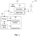
Fig. 1 illustrates anexample computing device 102. In the example,computing device 102 includes amemory device 104 and aprocessor 106 coupled tomemory device 104. In some examples, executable instructions are stored inmemory device 104 and executed byprocessor 106.Computing device 102 is configurable to perform one or more operations described herein by programming and/or configuringprocessor 106. For example,processor 106 may be programmed by encoding an operation as one or more executable instructions and providing the executable instructions inmemory device 104. -
Memory device 104 is one or more devices operable to enable information such as executable instructions and/or other data to be stored and/or retrieved.Memory device 104 may include one or more computer readable media, such as, without limitation, hard disk storage, optical drive/disk storage, removable disk storage, flash memory, non-volatile memory, ROM, EEPROM, random access memory (RAM), etc.Memory device 104 may be configured to store, without limitation, computer-executable instructions, transmitter identifiers, account identifiers, payment account information, and/or any other type of data.Memory device 104 may be incorporated in and/or separate fromprocessor 106. -
Processor 106 may include one or more processing units (e.g., in a multi-core configuration). The term processor, as used herein, refers to central processing units, microprocessors, microcontrollers, reduced instruction set circuits (RISC), application specific integrated circuits (ASIC), logic circuits, and any other circuit or processor capable of executing instructions to perform functions described herein. -
Computing device 102 includes acommunication interface 108 coupled toprocessor 106.Communication interface 108 is configured to be coupled in communication with one or more other devices, such as anothercomputing device 102, a network, etc.Communication interface 108 may include, without limitation, a serial communication adapter, a wired network adapter, a wireless network adapter, a mobile telecommunications adapter, a radio frequency (RF) receiver, a radio frequency identification (RFID) reader, a keyless entry receiver, and/or any other device capable of communicating with one or more other devices.Communication interface 108 may transmit information to and/or receive information from one or more devices. In one example, acommunication interface 108 of onecomputing device 102 may transmit a user profile to acommunication interface 108 ofanother computing device 102. - In some examples,
computing device 102 may be used in combination with auser interface 110 to interact withuser 112, such as an operator of a vehicle. As shown inFig. 1 ,user interface 110 is separate fromcomputing device 102.User interface 110 may communicate withprocessor 106 directly or indirectly through one or more communication interfaces 108. In at least one example,user interface 110 may be completely or at least partially included withincomputing device 102. -
User interface 110 may be configured to display information to auser 112. In the example,user interface 110 includes adisplay device 114, such as a cathode ray tube (CRT), a liquid crystal display (LCD), an organic LED (OLED) display, an "electronic ink" display, and/or other device suitable to display information. In some examples,user interface 110 includes an in-vehicle user interface, such as a display device of a navigation system and/or a media system. As used herein, "in-vehicle" user interface includes an interface coupled, mounted and/or secured to a vehicle (e.g., a vehicle dashboard) and accessible to at least oneuser 112 while present within the vehicle. Additionally, or alternatively,user interface 110 may include an audio output device (e.g., an audio adapter and/or a speaker, etc.). -
User interface 110 may include aninput device 116 to receive one or more inputs fromuser 112.Input device 116 may include, without limitation, a button, a knob, a keypad, a pointing device, a mouse, a touch sensitive panel (e.g., a touch pad or a touchscreen), a gyroscope, a position detector, and/or an audio input (e.g., a microphone). In various examples,user interface 110 may include a single component, such as a touchscreen display, incorporating bothdisplay device 114 andinput device 116. - As described herein,
computing device 102 may include one or more devices, servers, and/or controllers of the systems and/or methods described herein. -
Fig. 2 illustrates an example system 200 that may be used to charge an electricallypowered vehicle 202. In the example, system 200 includes avehicle charging station 204 coupled tovehicle 202. Moreover, in the example, chargingstation 204 includes acharging device 206 and apower source 208 that is coupled to chargingdevice 206.Power source 208 may include a power grid of an electric utility company, a generator, a battery, an inductor, and/or any other device or system capable of providing electricity to chargingdevice 206. -
Vehicle 202 includes at least oneenergy storage device 210, such as a battery and/or a capacitor, coupled to amotor 212. In the example,vehicle 202 includesvehicle controller 214 and in-vehicle user interface 216 coupled tovehicle controller 214. Whilevehicle controller 214 is illustrated as being a single component and is described with reference to multiple functions herein, it should be appreciated thatvehicle controller 214 may include multiple, separate controllers disposed throughoutvehicle 202 in other examples. As such, each of the multiple vehicle controllers may be associated with one or more of the functions described herein. - In the example system 200, a charging
conduit 218 is releasably coupled between chargingstation 204 andenergy storage device 210 and/or tovehicle controller 214. Chargingconduit 218 may permit energy transfer frompower source 208 tovehicle 202. Alternatively, a wireless conduit may permit energy transfer frompower source 208 tovehicle 202, as shown, for example, inFig. 3 . Regardless of the type of conduit employed, energy is generally transferred during a charging process frompower source 208 toenergy storage device 210 to chargeenergy storage device 210. - Referring again to
Fig. 2 , chargingconduit 218 may include at least one conductor for supplying electrical energy toenergy storage device 210 and/or to any other component withinvehicle 202, and at least one conductor for transmitting information to, and/or receiving information from,vehicle controller 214 and/or any other component withinvehicle 202. Chargingconduit 218 may couple tovehicle 202 at a chargingreceptacle 220. When chargingconduit 218 includes at least one power conductor (not shown) and at least one data conductor (not shown), chargingreceptacle 220 may include an integrated power-data receptacle to connect to both the power and data conductors. - Additionally, or alternatively, charging
conduit 218 may include a cable with one or more conductors for supplying electricity tovehicle 202, without a separate and dedicated conductor for communicating information to/fromvehicle 202. In such an example, information may be embedded in one or more power signals transmitted through chargingconduit 218 betweenvehicle charging station 204 andvehicle 202. In still other examples, data may be communicated betweenvehicle 202 and/or chargingstation 204 through a wireless connection. Chargingreceptacle 220 may be configured differently in various examples to provide appropriate connections between chargingstation 204 andvehicle 202. - As shown, charging
device 206 is coupled to aserver 222 through anetwork 224.Server 222 may communicate with chargingdevice 206, for example, to acknowledge/confirm an aspect of the user profile, to communicate a user response to an electronic message, and/or to perform any other function that enables system 200 to function as described herein.Network 224 may include, without limitation, the Internet, a local area network (LAN), a wide area network (WAN), a wireless LAN (WLAN), a mesh network, a virtual private network (VPN), a cellular network, and/or any other network that enables system 200 to function as described herein. In various examples, one or more of chargingdevice 206,vehicle controller 214, andserver 222 are connected to network 224. - Further, one or more of charging
device 206,vehicle controller 214, and/orserver 222 may be instances ofcomputing device 102. It should be appreciated that chargingdevice 206,vehicle controller 214, and/orserver 222 may include more or less components than illustrated in thecomputing device 102 in other examples. - Methods and systems described herein may include communicating information to and/or from an electrically powered vehicle, a vehicle charging station, and/or other devices. Communicating information may generate efficiency and/or increase safety and security for a user and/or the user's information, while providing additional functionality. In various examples, information may be communicated prior to initiating a charging process, during the charging process, and/or after the charging process.
- In the example,
controller 214 ofvehicle 202 includesmemory device 104 andprocessor 106.Memory device 104 stores at least one user profile. The user profile may include, without limitation, billing information, contact information foruser 112, an alert, a user preference, a vehicle identification, a vehicle manufacturer, a vehicle model, an AC profile, a limitation ofenergy storage device 210, a type ofenergy storage device 210, and/or other information related tovehicle 202, chargingstation 204, and/or a charging process, etc. - A user preference may include a charging time, a dollar amount, a price per unit power threshold, a voltage level, a current level, a rate threshold, a process for mitigating charging errors, a process for presenting/handling alerts, a request for a charge-time remaining indicator, a request to process/ignore charging
station 204 diagnostics, and/or other information or preferences associated with a user, etc. In at least one example, a user preference may be based on a location. For example, a user preference may request sufficient energy transfer to permit avehicle 202 to return to a user's residence, which may be less than a complete charge ofenergy storage device 210. In such an example,controller 214 may communicate with a navigation system (including in-vehicle user interface 216) to determine a location ofvehicle 202, a location of the user's residence, and estimate energy required to return to the user's residence. - Prior to communicating the user profile to charging
station 204,vehicle 202 may detect chargingstation 204. In the example, detection may be initiated by eithervehicle 202 or chargingstation 204, but preferably results in each ofvehicle 202 and chargingstation 204 detecting the other. - In the example,
vehicle 202 and/or chargingstation 204 may be detected by one or more sensors. In one example, chargingreceptacle 220 may include a sensor to detect the presence of chargingconduit 218 inserted therein. The sensor may include, for example, a switch. The sensor permitsvehicle 202 and/orvehicle controller 214 to detect chargingconduit 218, thereby detecting chargingstation 204. Conversely, a sensor may be associated with chargingconduit 218, such that chargingstation 204 detectsvehicle 202 when chargingconduit 218 is inserted into chargingreceptacle 220. In another example, chargingstation 204 may includes a weight sensor to detect the presence ofvehicle 202 over chargingstation 204. - Additionally, or alternatively, charging
station 204 may utilize communication in order to detectvehicle 202, or vice-versa. Specifically, for example, chargingdevice 206 may initiate communication by transmitting an identification signal to its generally vicinity viacommunication interface 108. When avehicle 202 pulls up to chargingstation 204,vehicle 202 may receive the identification signal and generate a response signal throughcommunication interface 108 to establish communication with chargingstation 204. Consequently,vehicle 202 detects chargingstation 204, and chargingstation 204 detectsvehicle 202. It should be appreciated that an identification signal may be transmitted by a vehicle and received by a charging station in other examples. - In the example, the identification signal may be transmitted consistently from
vehicle 202 or chargingstation 204. Additionally, or alternatively, the identification signal may be transmitted in response to a user input. For example,user 112 may pull up to chargingstation 204 and provide an input to in-vehicle user interface 216, causingprocessor 106, in combination withcommunication interface 108, to transmit an identification signal.Charging station 204, in turn, receives the identification signal and responds. As such, each ofvehicle 202 and chargingstation 204 has detected the other. It should be appreciated that various signals in various orders may be communication between,vehicle controller 214,vehicle 202, chargingstation 204 and/or chargingdevice 206 to permit detection of one or both ofvehicle 202 and chargingstation 204. - Once charging
station 204 is detected,processor 106 ofcontroller 214 retrieves the user profile frommemory device 104 and communicates the user profile to chargingstation 204. In the example,processor 106 automatically retrieves the user profile frommemory device 104 and automatically communicates the user profile to chargingstation 204. In other examples, a user input to inputdevice 116 may be required to retrieve and/or communicate the user profile. In at least one example, a user input may be required to selected one of a plurality of user profiles stored inmemory device 104. - Once charging
station 204 receives the user profile, chargingstation 204 may enable energy transfer from thepower source 208 tovehicle 202 at least partially based on the user profile. Accordingly, at least a portion of information required by chargingstation 204 to initiate a charging process is communicated to chargingstation 204, withoutuser 112 manually entering the content of the user profile. In this manner, communicating the user profile to chargingstation 204 may provide increased safety, security and efficiency over known methods of entering information to a charging station. Specifically, for example, billing information is not entered to chargingstation 204 in plain view of others. Additionally, or alternatively, communicating the user profile fromvehicle controller 214 may provide increased safety, security and efficiency over known methods, because a payment device (e.g., a credit card, debit card, key-chain radio frequency identification (RFID) device, a mobile telephone, or other device linked to a payment account) is not publically handled byuser 112, such that it may become lost. Moreover, the user profile, including billing/contact information, is passed electronically so that user profile is embedded in a communication betweenvehicle controller 214 and chargingstation 204 and outside the plain view of others. - Apart from billing and contact information, the user profile may include other information, such as one or more user preferences. In the example, for example, the user profile may include a charging time. When
user 112 pulls up to chargingstation 204, chargingstation 204 may chargevehicle 202 according to the charging time defined in the user profile without one or more inputs fromuser 112. - Similarly, the user profile may include a preferred notification when an alert is generated, so that
user 112 is notified in a particular manner if, for example, a charging error occurs. In another example, the user profile may include information related to a charging rate threshold (dollar per watt), such that charging station automatically initiates a charging processes with the current rate of energy is below the rate threshold. Further, as the number and variety of electrically powered vehicles grows, a number of variables necessary to properly/safely chargevehicle 202 may also increase. For example, one type ofvehicle 202 may require 240VAC to charge, while another type ofvehicle 202 may require 480VAC to charge. The user profile may be used in various examples to provide any and/or all information to chargingstation 204 to facilitate charging, thereby potentially obviating a user's need to directly interact with the chargingstation 204. - In the example, charging
device 206 may evaluate the user profile prior to initiating an energy transfer to verify information and/or confirm if additional information is needed. For example, chargingdevice 206 may communicate throughnetwork 224 to verify and/or authorize billing information prior to permitting energy transfer tovehicle 202. In another example, chargingdevice 206 may access one or more networks to verify information and/or provide further functionality during a charging process. For example, the content of a user profile may provide a basis to offer one or more advertisements touser 112 before, during or after a charging process. - Additionally, or alternatively, a user profile may include only a portion of the information necessary to initiate a charging process. For example, a user profile may include billing information, contact information, and an AC profile, but not include a charge time. In this manner, a user profile may supply information routinely entered by a user, but does not include other information that a user may want to adjust for each charging process. Information not included in the user profile may be provided by a user to charging
station 204, for example, through in-vehicle user interface 216, consistent with the methods described herein. - The user profile may be defined by
user 112 in several different ways. In one example, the user profile may be defined by use ofdisplay device 114 andinput device 116 of in-vehicle user interface 216.Vehicle controller 214 may display multiple messages touser 112 throughdisplay device 114 to elicit one or more inputs fromuser 112 to inputdevice 116 to define the user profile. For example,user 112 may be prompted atdisplay device 114 to enter a preferred charging time. In response to the prompt,user 112 may enter an input toinputs device 116 to enter or select about 30 minutes, about 2 hours, about 4 hours, or another suitable time, etc. Once defined, the user profile is stored inmemory device 104 ofvehicle controller 214 for communication to chargingstation 204. In several examples, the user profile may be defined through another interface tovehicle controller 214. For example, a user communication device, such as a smartphone or personal computer, may communicate, vianetwork 224, withcommunication interface 108 ofvehicle controller 214 to define the user profile. It should be appreciated that a user profile may be defined by entering a new user profile and/or editing an existing user profile. Further, multiple user profiles may be created and/or edited. Specifically, for example, multiple user profiles may include, without limitation, a short charge profile, medium charge profile, long charge profile, top off profile, etc. - In the example,
vehicle 202 includes in-vehicle user interface 216 andvehicle controller 214 coupled in communication with in-vehicle user interface 216. In-vehicle user interface 216 includes at least oneinput device 116 configured to receive an input fromuser 112.Vehicle controller 214 is configured to receive a user input from in-vehicle user interface 216 and communicate a charging parameter tovehicle charging station 204 in response to the user input. - Charging parameters may include any parameters to initiate, alter and/or terminate a charging process. In the example a charging parameter may include, without limitation, an instruction related to a charging process, a selection of a charging process option, billing information, contact information, an alert, a user preference, a vehicle model, an AC profile, a limitation of
energy storage device 210, a type ofenergy storage device 210, and/or any other information associated with the charging process,vehicle 202, chargingstation 204 and/oruser 112. - In the example,
user 112 may be able to communicate with chargingstation 204 from withinvehicle 202. As such,user 112 is able to communicate with chargingstation 204 without exitingvehicle 202, thereby providing for the safety, security and/or convenience ofuser 112. Moreover, communicating billing information, for example, to chargingstation 204 from withinvehicle 202 may provide additional privacy and security, as compared to entering such information outsidevehicle 202 in plain view of others. - Further, in several examples, use of in-
vehicle user interface 216 may permit additional functionality ofvehicle 202, without the addition of display and/or input devices. More specifically, in the example, in-vehicle user interface 216 may be included in a system ofvehicle 202 intended to perform at least one other function, such as navigation, entertainment, etc. For example, in-vehicle user interface 216 may be incorporated with an audio system, a visual system, a navigation system, a media system and/or any other system withinvehicle 202. In one example, in-vehicle user interface 216 includes a touchscreen display (e.g.,display device 114 and input device 116) of a navigation system. A navigation system may include any system suitable for providing location and/or or direction information. A media system may include any system suitable to provide radio, CD, MP3, video, DVD, gaming, telecommunications and/or other media functionality. - In several examples, in-
vehicle user interface 216 may includedisplay device 114 andinput device 116.Input device 116 is provided to receive one or more inputs fromuser 112.Display device 114 may be utilized to solicit inputs fromuser 112 and/or display one or more messages from chargingstation 204. In one example, chargingstation 204 may transmit a message tovehicle 202 requesting a charging time. In turn,display device 114 displays a request for a charging time touser 112.User 112 may provide an input to inputdevice 116 entering or selecting a charging time.Vehicle controller 214, in turn, transmits a charging parameter (e.g., the charging time) to chargingstation 204. In another example, a user profile may contain only a portion of information needed to initiate a charging process forvehicle 202. After chargingstation 204 receives the user profile, chargingstation 204 may transmit a message requesting information not included in the user profile. In turn, a request may be displayed touser 112 atdisplay device 114, anduser 112 may then select or enter, viainput device 116, information requested by chargingstation 204.Vehicle controller 214 receives the one or more user inputs and communicates at least one charging parameter, based on the user inputs, to provide the information requested by chargingstation 204. - It should be appreciated that in one or more examples, a user input to in-
vehicle user interface 216 may be in response to a message originating from a device other than chargingstation 204. - In the example, communication between charging
station 204 and in-vehicle user interface 216 may be controlled byvehicle controller 214. In such examples,vehicle controller 214 may be configured to transmit and/or receive messages to and/or from in-vehicle user interface 216 or other components orvehicle 202 according to one or more formats and/or protocols. In the example,vehicle 202 includes a packet-based, wired connection betweenvehicle controller 214 and in-vehicle user interface 216. In-vehicle user interface 216 may include, for example, a vehicle audio system. As such,vehicle controller 214 may be configured to receive and/or transmit message according to a radio data system (RDS) format to permitvehicle controller 214 to transmit/receive formatted messages to/from the vehicle audio system. Additionally, or alternatively,vehicle controller 214 may be configured to transmit and/or receive messages to and/or from chargingstation 204 according to one or more formats and/or protocols. For example,vehicle controller 214 may be configured to transmit packet-based messages to chargingstation 204 through chargingconduit 218. - In the example, the functionality of charging
station 204 may be affected whenvehicle 202 is coupled to chargingstation 204. For example, a display device and/or an input device of chargingstation 204 may be disabled when chargingstation 204 is connected in communication withvehicle 202. Disabling the display device and/or input device of chargingstation 204 may prevent input of information from multiple sources and/or display of user information at chargingstation 204. In alternative examples, one or both of a display device and an input device of chargingstation 204 may be enabled, when chargingstation 204 is coupled in communication withvehicle 202. -
Fig. 3 illustratessystem 300 according to another example of the present disclosure.System 300 includes an electricallypowered vehicle 302 and avehicle charging station 304.Charging station 304 includes acharging device 306 and apower source 308 coupled to chargingdevice 306.Charging device 306 controls energy transfer frompower source 308 tovehicle 302. In this example, a magnetic/electric field 326 is radiated from chargingstation 304 to transfer energy tovehicle 302, and more specifically anenergy storage device 310 included invehicle 302. Contrary to the example ofFig. 2 , including chargingconduit 218, magnetic/electric field 326 permits wireless transfer of energy between chargingstation 304 andvehicle 302. It should be appreciated that wired energy transfer or wireless energy transfer may be used alone, or in combination, in one or more other examples. - In addition to
energy storage device 310,vehicle 302 includes amotor 312, avehicle controller 314, and an in-vehicle user interface 316 coupled tovehicle controller 314. In the example,vehicle controller 314 is coupled tonetwork 324 throughcommunication interface 108. As shown,communication interface 108 permits wireless communication betweenvehicle 302 and chargingstation 304, vianetwork 324. As indicated above,network 324 may include, without limitation, the Internet, a local area network (LAN), a wide area network (WAN), a wireless LAN (WLAN), a mesh network, a virtual private network (VPN), a cellular network, and/or any other network that enablessystem 300 to function as described herein. - In the example, because energy transfer and communication between charging
station 304 andvehicle 302 are wireless, auser 112 may initiate and complete a charging process, without exitingvehicle 302 to attached a charging conduit or enter information to chargingstation 304. By permittinguser 112 to remain in the vehicle during a charging process,system 300 provides increased security, safety and/or convenience touser 112 over know methods and systems for charging an electrically powered vehicle. It should be appreciated that in other examples, such as illustrated inFig. 2 , chargingconduit 218 may be automatically connected tovehicle 202 prior to a charging process, such that even when a physical connection for energy transfer is present,user 112 may complete a charging processes without exitingvehicle 202. - In the example, charging
station 304 includespower source 308 and chargingdevice 306 for controlling energy transfer frompower source 308 tovehicle 302.Charging device 306 is configured to transmit, vianetwork 324, a first electronic message touser 112 and receive, vianetwork 324, a second electronic message fromuser 112. The first electronic message including a condition related to at least one of the charging process andvehicle 302. The second electronic message including a user command related to the condition. - By transmitting the electronic message to
user 112, chargingdevice 306 is able to promptly notifyuser 112 of one or more conditions. In the example,vehicle controller 314 may be coupled to an on-board computer ofvehicle 302 to access information related to various sensors, such as tire pressure, window state, etc., and/or an alarm system ofvehicle 302 to receive alarm indication. Accordingly, conditions may include, without limitation, a status of a charging process, an amount of energy transferred, a status, a charging error, or other information related to the charging process. Additionally, or alternatively, the condition may include, without limitation the state of a window (i.e., open or closed), a tire pressure, oil change indicator, an unauthorized access (e.g., a break-in), a temperature, etc. The prompt notification of any of the conditions may permituser 112 to more quickly respond to the condition, which may increase efficiency and/or security whilevehicle 302 is charging. - In one example, a condition may include a charging error, and the first electronic message may indicate the charging error to
user 112. The first message may also indicate that the charging process has been suspended. If the error occurs after only 10 minutes into a two-hour charging process, for example,user 112 may not have realized the charging error until returning tovehicle 302 after a couple hours. By notifyinguser 112 of the error promptly,user 112 may address the error and re-initiate the charging process, without the loss of substantial charging time. In the example, the user command of the second message may be sufficient to mitigate the charging error and re-imitate charging ofvehicle 302. For example, a user command may accept a longer charge time, a different voltage or a partial charge in order to resume a charging process. - In another example,
user 112 may be notified via the first electronic message that one or more windows ofvehicle 302 are open during inclement weather.User 112 may be able to promptly return tovehicle 302 to adjust one or more windows as dictated by weather. Alternatively, the user command of the second message may directvehicle controller 314 to adjust (directly or through a different computing device) the state of the windows according to the weather. - In yet another example, a charging process may cease based on an energy rate (dollar per watt) that exceeds a user preference. When the charging process ceases, charging
device 306 and/orvehicle controller 314 may transmit the first electronic message touser 112 indicating the current energy rate. In response,user 112 may transmit the second message including a command to re-initiate charging ofvehicle 302, notwithstanding the energy rater exceeding the user preference. It should be appreciated that various other alterations and/or changes may be implemented by a user via a user command in the second electronic message. In at least one example,user 112 may initiate a message to chargingdevice 306 and/orcontroller 314, without a prior electronic message from chargingdevice 306. - The first and second electronic messages may include a SMS message, a voicemail message, an email message or other electronic message suitable for transmission over
network 224, etc. The electronic messages may be received/transmitted byuser 112 at acommunication device 328, such as, without limitation, a cellular phone, a pager, a smartphone, a personal computer, a laptop, a tablet, a workstation, a security system, or any other device suitable to receive and/or send an electronic message. - As explained above, charging
station 304 may communicate withvehicle 302 in response to the second message. Alternatively, chargingstation 304 may communicate to a third party in response to the second message. For example, when a condition indicates an unauthorized access ofvehicle 302 or chargingstation 304, a message to a third-party may include a message to security personnel, a local authorities or police. In another example, when a condition indicated all four tire are flat, a message to a third party may include a message to security personnel, a local authorities or police, indicating vandalism and/or tires ofvehicle 302 have been slashed. Messages to one or more other third-parties related to the condition of the first message and/or a user command of the second message should be considered within the scope of the present disclosure. - Methods illustrated in
Figs. 4-6 are described below with reference tosystem 300. It should be appreciated that the methods described herein are not limited tosystem 300. Likewise,system 300 should not be understood to be limited to one or more of the methods described herein.Fig. 4 illustratesmethod 400 according to an example of the present disclosure.Method 400 includes detecting 402 a vehicle charging station, retrieving 404 a user profile from a memory device in the electrically powered vehicle, and communicating 406 the user profile to the vehicle charging station, the user profile including billing information. -
Method 400 may include receiving at least one message fromvehicle charging station 204 and displaying, at adisplay device 114, the at least one message touser 112.Method 400 may also include receiving a user profile fromuser 112 and storing the user profile inmemory device 104. Furthermore,method 400 may include receiving an input to in-vehicle user interface 316 to define the user profile. -
Fig. 5 illustratesmethod 500 according to an example of the present disclosure.Method 500 includes receiving 502, at in-vehicle user interface 316, at least one user input and communicating 504, viavehicle controller 314, a charging parameter tovehicle charging station 304 in response to the at least one user input.Method 500 may include displaying, at in-vehicle user interface 316, at least one charging option touser 112, and wherein the at least one user input selects the at least one charging option.Method 500 may also include displaying, at in-vehicle user interface 316, at least one message fromvehicle charging station 304.Method 500 may include establishing a wireless connection between electricallypowered vehicle 302 andvehicle charging station 304. -
Fig. 6 illustratesmethod 600 according to an example of the present disclosure.Method 600 includes controlling 602, at the charging device, a charging process including energy transfer between the power source and the electrically powered vehicle, transmitting 604, vianetwork 324, a first electronic message touser 112 and receiving 606, vianetwork 324, a second electronic message. The first electronic message includes at least one condition related to at least one of the charging process andelectrically power vehicle 302. The second electronic message includes a user command related to the at least one condition. -
Method 600 may include transmitting the user command to electricallypowered vehicle 302.Method 600 may also include transmitting a third message to a third-party in response to the user command. Moreover,method 600 may include altering the charging process in response to the user command to mitigate the charging error. - While the above functions and systems have been described with reference to system 200 or
system 300, it should be appreciated that various system examples may be employed to enable one or more of the functions described herein. More specifically, systems described herein should not be understood to be limited to one or more methods described herein, while methods described herein should not be understood to be limited to the particular examples illustrated herein. Accordingly, several different system examples and/or several different method examples are described herein without limitation. - The methods and systems described herein are not limited to the specific examples described herein. For example, components of each system and/or steps of each method may be used and/or practiced independently and separately from other components and/or steps described herein. In addition, each component and/or step may also be used and/or practiced with other systems and methods.
- While certain functions and/or operations are described above with respect to particular devices, it is contemplated that any device may perform one or more of the described operations. Systems and methods described herein may limit the manual interaction between a charging station and a user of the charging station. Further, the systems and methods described herein may efficiency and conveniently utilize one or more in-vehicle interfaces to communicate with charging station, rather than known interfaces, which are specific to and/or included in charging stations. Further still, the systems and methods described herein may provide communications between a user and a charging station, while the user is away from the charging station.
- Some examples involve the use of one or more electronic or computing devices. Such devices typically include a processor or controller, such as a general purpose central processing unit (CPU), a graphics processing unit (GPU), a microcontroller, a reduced instruction set computer (RISC) processor, an application specific integrated circuit (ASIC), a programmable logic circuit (PLC), and/or any other circuit or processor capable of executing the functions described herein. The methods described herein may be encoded as executable instructions embodied in a computer readable medium, including, without limitation, a storage device and/or a memory device. Such instructions, when executed by a processor, cause the processor to perform at least a portion of the methods described herein.
- The above represents examples only, and the scope of the invention is defined by the appended claims.
Claims (12)
- A vehicle charging station (204) for charging an electrically powered vehicle (202), said vehicle charging station comprising:a power source (208); anda charging device (206) coupled to said power source, said charging device configured to:control a charging process between said power source and an electrically powered vehicle;transmit, via at least one network (224), a first electronic message to a user, the first electronic message including a charging error and an indication that the charging process has been suspended; andreceive, via the at least one network, a second electronic message from the user, the second electronic message including a user command that indicates acceptance of longer charging time, a different voltage, or a partial charge in order to allow the charging process to be resumed;resume the charging process in response to receiving the user command of the second electronic message,wherein said charging device (206) is configured to receive a user profile from the electrically powered vehicle (202), wherein the user profile includes contact information, and wherein the charging device is configured to transmit the first message based on the contact information.
- The vehicle charging station of Claim 1, wherein the first message includes one of a SMS message and an email message.
- The vehicle charging station of Claim 2, wherein the at least one network (224) includes a wireless cellular network.
- The vehicle charging station of Claim 1, 2 or 3, wherein said charging device (206) is configured to alter the charging process in response to the user command.
- The vehicle charging station of any one of Claims 1 to 4, wherein said charging device (206) is configured to transmit the user command to the electrically powered vehicle (202).
- The vehicle charging station of Claim 5, wherein the first message includes a state of the electrically powered vehicle (202), and wherein the second electronic message includes a user command instructing the electrically powered vehicle to change the state.
- The vehicle charging station of Claim 6, wherein the first message indicates a state of at least one window of the electrically powered vehicle (202).
- The vehicle charging station of any one of Claims 1 to 7, wherein the first message includes an alarm indicating unauthorized access of the electrically powered vehicle (202) and/or vehicle charging station (204).
- A method for use in charging an electrically powered vehicle (202) at a charging station (204), the vehicle charging station including a power source (208) and a charging device (206) coupled to the power source, said method comprising:controlling, at the charging device (206), a charging process between the power source and the electrically powered vehicle;transmitting, via at least one network, a first electronic message to a user, the first electronic message including a charging error and an indication that the charging process has been suspended ; andreceiving, via the at least one network, a second electronic message, from the user, the second electronic message including a user command that indicates acceptance of longer charging time, a different voltage, or a partial charge in order to allow the charging process to be resumed; .resuming the charging process in response to receiving the user command of the second electronic message,wherein said charging device (206) is configured to receive a user profile from the electrically powered vehicle (202), wherein the user profile includes contact information, and wherein the charging device is configured to transmit the first message based on the contact information.
- The method of Claim 9, wherein transmitting via at least one network includes transmitting via a cellular network, preferably by transmitting one of a SMS message and an email message.
- The method of Claim 10, further comprising transmitting the user command to the electrically powered vehicle (202), and/or transmitting a third message to a third-party in response to the user command.
- One or more non-transitory computer-readable storage media having computer-executable instructions embodiments thereon, wherein when executed by at least one processor, said computer-executable instruction cause the processor to perform the method of any one of Claims 9 to 11.
Applications Claiming Priority (2)
| Application Number | Priority Date | Filing Date | Title |
|---|---|---|---|
| US13/206,026 US9035607B2 (en) | 2011-08-09 | 2011-08-09 | Vehicle charging stations and methods for use in charging an electrically powered vehicle |
| EP12179541.3A EP2556986B1 (en) | 2011-08-09 | 2012-08-07 | Vehicle charging stations and methods for use in charging an electrically powered vehicle |
Related Parent Applications (1)
| Application Number | Title | Priority Date | Filing Date |
|---|---|---|---|
| EP12179541.3A Division EP2556986B1 (en) | 2011-08-09 | 2012-08-07 | Vehicle charging stations and methods for use in charging an electrically powered vehicle |
Publications (3)
| Publication Number | Publication Date |
|---|---|
| EP4166377A1 EP4166377A1 (en) | 2023-04-19 |
| EP4166377B1 true EP4166377B1 (en) | 2025-03-12 |
| EP4166377C0 EP4166377C0 (en) | 2025-03-12 |
Family
ID=46851808
Family Applications (2)
| Application Number | Title | Priority Date | Filing Date |
|---|---|---|---|
| EP22198110.3A Active EP4166377B1 (en) | 2011-08-09 | 2012-08-07 | Vehicle charging stations and methods for use in charging an electrically powered vehicle |
| EP12179541.3A Active EP2556986B1 (en) | 2011-08-09 | 2012-08-07 | Vehicle charging stations and methods for use in charging an electrically powered vehicle |
Family Applications After (1)
| Application Number | Title | Priority Date | Filing Date |
|---|---|---|---|
| EP12179541.3A Active EP2556986B1 (en) | 2011-08-09 | 2012-08-07 | Vehicle charging stations and methods for use in charging an electrically powered vehicle |
Country Status (6)
| Country | Link |
|---|---|
| US (1) | US9035607B2 (en) |
| EP (2) | EP4166377B1 (en) |
| JP (1) | JP2013048544A (en) |
| KR (1) | KR20130018611A (en) |
| CN (1) | CN102957184B (en) |
| AU (1) | AU2012207001A1 (en) |
Families Citing this family (27)
| Publication number | Priority date | Publication date | Assignee | Title |
|---|---|---|---|---|
| FR2992274B1 (en) * | 2012-06-20 | 2016-03-11 | Renault Sas | METHOD FOR RECHARGING A BATTERY OF A STOP HYBRID VEHICLE |
| US9971353B2 (en) * | 2012-07-03 | 2018-05-15 | Qualcomm Incorporated | Systems, methods, and apparatus related to electric vehicle parking and wireless charging |
| EP3026787B1 (en) * | 2013-06-26 | 2018-11-28 | Nissan Motor Co., Ltd | Charging device and contactless power supply device |
| US9409492B2 (en) * | 2014-04-21 | 2016-08-09 | Honda Motor Co., Ltd. | Method for precise demand response and control, and a system thereof |
| CN104092265A (en) * | 2014-07-27 | 2014-10-08 | 比瑞科技(深圳)有限公司 | Intelligent vehicle-mounted charger |
| US9827865B2 (en) | 2014-12-30 | 2017-11-28 | General Electric Company | Systems and methods for recharging vehicle-mounted energy storage devices |
| US10300804B2 (en) | 2015-04-29 | 2019-05-28 | General Electric Company | Apparatus and method for automated positioning of a vehicle |
| US9840156B2 (en) * | 2015-08-14 | 2017-12-12 | Siemens Industry, Inc. | Automatically selecting charging routine for an electric vehicle by balancing utility and user considerations |
| CN108349402B (en) * | 2015-11-09 | 2022-05-24 | 法拉第未来公司 | Vehicle charging system |
| US11539704B2 (en) * | 2015-11-13 | 2022-12-27 | Ford Global Technologies, Llc | Method and apparatus for secure wireless vehicle bus communication |
| US9987938B2 (en) | 2015-12-04 | 2018-06-05 | General Electric Company | Energy storage device, exchange apparatus, and method for exchanging an energy storage device |
| US20180370379A1 (en) * | 2015-12-21 | 2018-12-27 | Faraday&Future Inc. | Systems and methods for integrated vehicle charging and content delivery |
| FR3057409B1 (en) * | 2016-10-06 | 2019-08-30 | Renault S.A.S | SYSTEM AND METHOD FOR MONITORING LEAKAGE CURRENT DURING THE LOAD OF AN ELECTRIC VEHICLE |
| GB2567629B (en) * | 2017-10-13 | 2022-09-21 | Urban Electric Networks Ltd | Retractable charging station |
| DE102018005252A1 (en) * | 2018-07-02 | 2020-01-02 | Daimler Ag | Method for operating a vehicle |
| WO2020026681A1 (en) * | 2018-07-31 | 2020-02-06 | パナソニックIpマネジメント株式会社 | Charging management system, charging management method, and program |
| JP6756783B2 (en) * | 2018-08-09 | 2020-09-16 | トヨタ自動車株式会社 | In-vehicle control system and vehicle |
| US10933767B2 (en) * | 2019-01-04 | 2021-03-02 | Hyundai Motor Company | Electric vehicle energy sharing marketplace |
| CN109888921A (en) * | 2019-03-01 | 2019-06-14 | 武汉华沃电源技术有限公司 | A kind of movable-type intelligent network system |
| CN110588424A (en) * | 2019-08-15 | 2019-12-20 | 福建星网智慧软件有限公司 | Method for managing charging of charging pile without network and computer readable storage medium |
| US11338691B2 (en) | 2019-09-23 | 2022-05-24 | Abb Schweiz Ag | Electric vehicle charging using tire positions |
| FI128774B (en) * | 2019-11-04 | 2020-11-30 | Liikennevirta Oy / Virta Ltd | Method and device for evaluating the reliability of charging station for electric vehicles |
| DE102020106542A1 (en) * | 2020-03-10 | 2021-09-16 | ME Energy - Liquid Electricity GmbH | CHARGING COLUMN |
| DE102020117836A1 (en) | 2020-07-07 | 2022-01-13 | Dr. Ing. H.C. F. Porsche Aktiengesellschaft | System and method for authentication of a charging process for an electric vehicle at a charging station |
| US20240227612A9 (en) * | 2022-10-24 | 2024-07-11 | Volvo Car Corporation | Battery charging system with enhanced time-based charging and battery health monitoring and notification |
| US20240227607A9 (en) * | 2022-10-24 | 2024-07-11 | Volvo Car Corporation | Battery charging system with enhanced time-based charging |
| KR20240072070A (en) * | 2022-11-15 | 2024-05-23 | 현대자동차주식회사 | Apparatus amd method for power transfer supporting mobility needs function, communication device therefor |
Family Cites Families (18)
| Publication number | Priority date | Publication date | Assignee | Title |
|---|---|---|---|---|
| EP0412051B1 (en) | 1989-07-31 | 1993-09-22 | Maschinenfabrik Rieter Ag | Device for exchanging and loading of energy accumulators for transportation vehicles |
| US5563491A (en) | 1992-03-30 | 1996-10-08 | Tseng; Ling-Yuan | Combined parking meter and electric-vehicle battery charger with remote status receiver |
| US5462439A (en) * | 1993-04-19 | 1995-10-31 | Keith; Arlie L. | Charging batteries of electric vehicles |
| US6067008A (en) * | 1993-05-25 | 2000-05-23 | Intellectual Property Development Associates Of Connecticut, Inc. | Methods and apparatus for inputting messages, including advertisements, to a vehicle |
| US10011247B2 (en) * | 1996-03-27 | 2018-07-03 | Gtj Ventures, Llc | Control, monitoring and/or security apparatus and method |
| US6429773B1 (en) * | 2000-10-31 | 2002-08-06 | Hewlett-Packard Company | System for remotely communicating with a vehicle |
| US6614204B2 (en) | 2001-12-21 | 2003-09-02 | Nicholas J. Pellegrino | Charging station for hybrid powered vehicles |
| JP2004142661A (en) * | 2002-10-25 | 2004-05-20 | Denso Corp | Power supply management device for vehicle |
| GB0611332D0 (en) | 2006-06-08 | 2006-07-19 | Elektromotive Ltd | Charging station |
| US9853488B2 (en) | 2008-07-11 | 2017-12-26 | Charge Fusion Technologies, Llc | Systems and methods for electric vehicle charging and power management |
| US20100094496A1 (en) | 2008-09-19 | 2010-04-15 | Barak Hershkovitz | System and Method for Operating an Electric Vehicle |
| JP2010154646A (en) | 2008-12-25 | 2010-07-08 | Omron Corp | Apparatus and method for controlling charge, and program |
| US7906937B2 (en) * | 2009-06-02 | 2011-03-15 | Coulomb Technologies, Inc. | Overcurrent and ground fault protection in a networked charging station for electric vehicles |
| US20110106329A1 (en) * | 2009-11-03 | 2011-05-05 | GRIDbot, LLC | Methods and apparatus for charging station with sms user interface |
| SI2362362T1 (en) * | 2010-02-18 | 2013-07-31 | Kapsch Trafficcom Ag | Method for charging electric vehicles in geographically distributed charging stations |
| US20110276448A1 (en) | 2010-05-05 | 2011-11-10 | Harry Leonard Perper | Plug-in hybrid and electric vehicle charging system |
| CN201893567U (en) * | 2010-09-30 | 2011-07-06 | 国家电网公司 | Electric energy supply system for electric automobile |
| US20120173074A1 (en) | 2011-01-03 | 2012-07-05 | Christopher Charles Yasko | Monitoring systems and methods for providing remote notification of an electric vehicle status to a user |
-
2011
- 2011-08-09 US US13/206,026 patent/US9035607B2/en active Active
-
2012
- 2012-07-25 AU AU2012207001A patent/AU2012207001A1/en not_active Abandoned
- 2012-08-06 JP JP2012173563A patent/JP2013048544A/en active Pending
- 2012-08-07 EP EP22198110.3A patent/EP4166377B1/en active Active
- 2012-08-07 EP EP12179541.3A patent/EP2556986B1/en active Active
- 2012-08-08 KR KR1020120086739A patent/KR20130018611A/en not_active Withdrawn
- 2012-08-09 CN CN201210281945.6A patent/CN102957184B/en active Active
Also Published As
| Publication number | Publication date |
|---|---|
| CN102957184A (en) | 2013-03-06 |
| EP2556986B1 (en) | 2022-09-28 |
| US9035607B2 (en) | 2015-05-19 |
| EP2556986A2 (en) | 2013-02-13 |
| EP4166377C0 (en) | 2025-03-12 |
| EP2556986A3 (en) | 2017-06-28 |
| AU2012207001A1 (en) | 2013-02-28 |
| KR20130018611A (en) | 2013-02-25 |
| EP4166377A1 (en) | 2023-04-19 |
| CN102957184B (en) | 2016-12-21 |
| US20130038284A1 (en) | 2013-02-14 |
| JP2013048544A (en) | 2013-03-07 |
Similar Documents
| Publication | Publication Date | Title |
|---|---|---|
| EP4166377B1 (en) | Vehicle charging stations and methods for use in charging an electrically powered vehicle | |
| US20130041850A1 (en) | Electrically powered vehicles and methods for use in charging an electrically powered vehicle | |
| EP2556987A2 (en) | Vehicle controllers and methods for use in charging an electrically powered vehicle | |
| US9056553B2 (en) | Methods and systems for charging an electric vehicle | |
| JP6114531B2 (en) | Charging system, kiosk, and method of supplying current to a power storage device | |
| CN101870277B (en) | Vehicle charging authorization | |
| EP2587615B1 (en) | System, charging device, and method of supplying current to a power storage device | |
| EP2529973B1 (en) | power system for use in supplying power to at least an electric vehicle via a charging device and method for such a power system | |
| US20180027364A1 (en) | Electric vehicle, server apparatus, and communication information terminal | |
| EP3598603B1 (en) | Charging device, system, and method for controlling a charging device | |
| JP2013031363A (en) | Charging device for use in charging electric vehicles and method of providing electricity to electric vehicle | |
| KR20240016495A (en) | Charge and discharge cable device for electric vehicles |
Legal Events
| Date | Code | Title | Description |
|---|---|---|---|
| PUAI | Public reference made under article 153(3) epc to a published international application that has entered the european phase |
Free format text: ORIGINAL CODE: 0009012 |
|
| STAA | Information on the status of an ep patent application or granted ep patent |
Free format text: STATUS: REQUEST FOR EXAMINATION WAS MADE |
|
| 17P | Request for examination filed |
Effective date: 20220927 |
|
| AC | Divisional application: reference to earlier application |
Ref document number: 2556986 Country of ref document: EP Kind code of ref document: P |
|
| AK | Designated contracting states |
Kind code of ref document: A1 Designated state(s): AL AT BE BG CH CY CZ DE DK EE ES FI FR GB GR HR HU IE IS IT LI LT LU LV MC MK MT NL NO PL PT RO RS SE SI SK SM TR |
|
| RAP1 | Party data changed (applicant data changed or rights of an application transferred) |
Owner name: GE INTELLECTUAL PROPERTY LICENSING, LLC |
|
| GRAP | Despatch of communication of intention to grant a patent |
Free format text: ORIGINAL CODE: EPIDOSNIGR1 |
|
| STAA | Information on the status of an ep patent application or granted ep patent |
Free format text: STATUS: GRANT OF PATENT IS INTENDED |
|
| INTG | Intention to grant announced |
Effective date: 20241025 |
|
| GRAS | Grant fee paid |
Free format text: ORIGINAL CODE: EPIDOSNIGR3 |
|
| GRAA | (expected) grant |
Free format text: ORIGINAL CODE: 0009210 |
|
| STAA | Information on the status of an ep patent application or granted ep patent |
Free format text: STATUS: THE PATENT HAS BEEN GRANTED |
|
| AC | Divisional application: reference to earlier application |
Ref document number: 2556986 Country of ref document: EP Kind code of ref document: P |
|
| AK | Designated contracting states |
Kind code of ref document: B1 Designated state(s): AL AT BE BG CH CY CZ DE DK EE ES FI FR GB GR HR HU IE IS IT LI LT LU LV MC MK MT NL NO PL PT RO RS SE SI SK SM TR |
|
| REG | Reference to a national code |
Ref country code: GB Ref legal event code: FG4D |
|
| REG | Reference to a national code |
Ref country code: CH Ref legal event code: EP |
|
| REG | Reference to a national code |
Ref country code: DE Ref legal event code: R096 Ref document number: 602012081417 Country of ref document: DE |
|
| REG | Reference to a national code |
Ref country code: IE Ref legal event code: FG4D |
|
| U01 | Request for unitary effect filed |
Effective date: 20250409 |
|
| U07 | Unitary effect registered |
Designated state(s): AT BE BG DE DK EE FI FR IT LT LU LV MT NL PT RO SE SI Effective date: 20250415 |
|
| PG25 | Lapsed in a contracting state [announced via postgrant information from national office to epo] |
Ref country code: RS Free format text: LAPSE BECAUSE OF FAILURE TO SUBMIT A TRANSLATION OF THE DESCRIPTION OR TO PAY THE FEE WITHIN THE PRESCRIBED TIME-LIMIT Effective date: 20250612 |
|
| PG25 | Lapsed in a contracting state [announced via postgrant information from national office to epo] |
Ref country code: ES Free format text: LAPSE BECAUSE OF FAILURE TO SUBMIT A TRANSLATION OF THE DESCRIPTION OR TO PAY THE FEE WITHIN THE PRESCRIBED TIME-LIMIT Effective date: 20250312 |
|
| PG25 | Lapsed in a contracting state [announced via postgrant information from national office to epo] |
Ref country code: NO Free format text: LAPSE BECAUSE OF FAILURE TO SUBMIT A TRANSLATION OF THE DESCRIPTION OR TO PAY THE FEE WITHIN THE PRESCRIBED TIME-LIMIT Effective date: 20250612 |
|
| PG25 | Lapsed in a contracting state [announced via postgrant information from national office to epo] |
Ref country code: HR Free format text: LAPSE BECAUSE OF FAILURE TO SUBMIT A TRANSLATION OF THE DESCRIPTION OR TO PAY THE FEE WITHIN THE PRESCRIBED TIME-LIMIT Effective date: 20250312 |
|
| PG25 | Lapsed in a contracting state [announced via postgrant information from national office to epo] |
Ref country code: GR Free format text: LAPSE BECAUSE OF FAILURE TO SUBMIT A TRANSLATION OF THE DESCRIPTION OR TO PAY THE FEE WITHIN THE PRESCRIBED TIME-LIMIT Effective date: 20250613 |
|
| U20 | Renewal fee for the european patent with unitary effect paid |
Year of fee payment: 14 Effective date: 20250723 |
|
| PG25 | Lapsed in a contracting state [announced via postgrant information from national office to epo] |
Ref country code: SM Free format text: LAPSE BECAUSE OF FAILURE TO SUBMIT A TRANSLATION OF THE DESCRIPTION OR TO PAY THE FEE WITHIN THE PRESCRIBED TIME-LIMIT Effective date: 20250312 |
|
| PG25 | Lapsed in a contracting state [announced via postgrant information from national office to epo] |
Ref country code: PL Free format text: LAPSE BECAUSE OF FAILURE TO SUBMIT A TRANSLATION OF THE DESCRIPTION OR TO PAY THE FEE WITHIN THE PRESCRIBED TIME-LIMIT Effective date: 20250312 |
|
| PG25 | Lapsed in a contracting state [announced via postgrant information from national office to epo] |
Ref country code: CZ Free format text: LAPSE BECAUSE OF FAILURE TO SUBMIT A TRANSLATION OF THE DESCRIPTION OR TO PAY THE FEE WITHIN THE PRESCRIBED TIME-LIMIT Effective date: 20250312 |
|
| PG25 | Lapsed in a contracting state [announced via postgrant information from national office to epo] |
Ref country code: SK Free format text: LAPSE BECAUSE OF FAILURE TO SUBMIT A TRANSLATION OF THE DESCRIPTION OR TO PAY THE FEE WITHIN THE PRESCRIBED TIME-LIMIT Effective date: 20250312 |
|
| PG25 | Lapsed in a contracting state [announced via postgrant information from national office to epo] |
Ref country code: IS Free format text: LAPSE BECAUSE OF FAILURE TO SUBMIT A TRANSLATION OF THE DESCRIPTION OR TO PAY THE FEE WITHIN THE PRESCRIBED TIME-LIMIT Effective date: 20250712 |
|
| REG | Reference to a national code |
Ref country code: CH Ref legal event code: W10 Free format text: ST27 STATUS EVENT CODE: U-0-0-W10-W00 (AS PROVIDED BY THE NATIONAL OFFICE) Effective date: 20251119 |
|
| RAP4 | Party data changed (patent owner data changed or rights of a patent transferred) |
Owner name: DOLBY INTELLECTUAL PROPERTY LICENSING, LLC |
|
| U1H | Name or address of the proprietor changed after the registration of the unitary effect |
Owner name: DOLBY INTELLECTUAL PROPERTY LICENSING, LLC; US |
|
| PLBE | No opposition filed within time limit |
Free format text: ORIGINAL CODE: 0009261 |
|
| STAA | Information on the status of an ep patent application or granted ep patent |
Free format text: STATUS: NO OPPOSITION FILED WITHIN TIME LIMIT |
|
| REG | Reference to a national code |
Ref country code: CH Ref legal event code: L10 Free format text: ST27 STATUS EVENT CODE: U-0-0-L10-L00 (AS PROVIDED BY THE NATIONAL OFFICE) Effective date: 20260121 |
|
| 26N | No opposition filed |
Effective date: 20251215 |