EP4166269A1 - Lap fillet weld joint, production method thereof and member with closed cross section - Google Patents
Lap fillet weld joint, production method thereof and member with closed cross section Download PDFInfo
- Publication number
- EP4166269A1 EP4166269A1 EP21841286.4A EP21841286A EP4166269A1 EP 4166269 A1 EP4166269 A1 EP 4166269A1 EP 21841286 A EP21841286 A EP 21841286A EP 4166269 A1 EP4166269 A1 EP 4166269A1
- Authority
- EP
- European Patent Office
- Prior art keywords
- metal plate
- edge portion
- lap fillet
- weld joint
- fillet weld
- Prior art date
- Legal status (The legal status is an assumption and is not a legal conclusion. Google has not performed a legal analysis and makes no representation as to the accuracy of the status listed.)
- Granted
Links
Images






Classifications
-
- F—MECHANICAL ENGINEERING; LIGHTING; HEATING; WEAPONS; BLASTING
- F16—ENGINEERING ELEMENTS AND UNITS; GENERAL MEASURES FOR PRODUCING AND MAINTAINING EFFECTIVE FUNCTIONING OF MACHINES OR INSTALLATIONS; THERMAL INSULATION IN GENERAL
- F16B—DEVICES FOR FASTENING OR SECURING CONSTRUCTIONAL ELEMENTS OR MACHINE PARTS TOGETHER, e.g. NAILS, BOLTS, CIRCLIPS, CLAMPS, CLIPS OR WEDGES; JOINTS OR JOINTING
- F16B5/00—Joining sheets or plates, e.g. panels, to one another or to strips or bars parallel to them
- F16B5/08—Joining sheets or plates, e.g. panels, to one another or to strips or bars parallel to them by means of welds or the like
-
- B—PERFORMING OPERATIONS; TRANSPORTING
- B23—MACHINE TOOLS; METAL-WORKING NOT OTHERWISE PROVIDED FOR
- B23K—SOLDERING OR UNSOLDERING; WELDING; CLADDING OR PLATING BY SOLDERING OR WELDING; CUTTING BY APPLYING HEAT LOCALLY, e.g. FLAME CUTTING; WORKING BY LASER BEAM
- B23K9/00—Arc welding or cutting
- B23K9/02—Seam welding; Backing means; Inserts
- B23K9/025—Seam welding; Backing means; Inserts for rectilinear seams
-
- B—PERFORMING OPERATIONS; TRANSPORTING
- B23—MACHINE TOOLS; METAL-WORKING NOT OTHERWISE PROVIDED FOR
- B23K—SOLDERING OR UNSOLDERING; WELDING; CLADDING OR PLATING BY SOLDERING OR WELDING; CUTTING BY APPLYING HEAT LOCALLY, e.g. FLAME CUTTING; WORKING BY LASER BEAM
- B23K26/00—Working by laser beam, e.g. welding, cutting or boring
- B23K26/20—Bonding
- B23K26/21—Bonding by welding
- B23K26/24—Seam welding
- B23K26/242—Fillet welding, i.e. involving a weld of substantially triangular cross section joining two parts
-
- B—PERFORMING OPERATIONS; TRANSPORTING
- B23—MACHINE TOOLS; METAL-WORKING NOT OTHERWISE PROVIDED FOR
- B23K—SOLDERING OR UNSOLDERING; WELDING; CLADDING OR PLATING BY SOLDERING OR WELDING; CUTTING BY APPLYING HEAT LOCALLY, e.g. FLAME CUTTING; WORKING BY LASER BEAM
- B23K26/00—Working by laser beam, e.g. welding, cutting or boring
- B23K26/20—Bonding
- B23K26/21—Bonding by welding
- B23K26/24—Seam welding
- B23K26/244—Overlap seam welding
-
- B—PERFORMING OPERATIONS; TRANSPORTING
- B23—MACHINE TOOLS; METAL-WORKING NOT OTHERWISE PROVIDED FOR
- B23K—SOLDERING OR UNSOLDERING; WELDING; CLADDING OR PLATING BY SOLDERING OR WELDING; CUTTING BY APPLYING HEAT LOCALLY, e.g. FLAME CUTTING; WORKING BY LASER BEAM
- B23K26/00—Working by laser beam, e.g. welding, cutting or boring
- B23K26/20—Bonding
- B23K26/21—Bonding by welding
- B23K26/24—Seam welding
- B23K26/26—Seam welding of rectilinear seams
-
- B—PERFORMING OPERATIONS; TRANSPORTING
- B23—MACHINE TOOLS; METAL-WORKING NOT OTHERWISE PROVIDED FOR
- B23K—SOLDERING OR UNSOLDERING; WELDING; CLADDING OR PLATING BY SOLDERING OR WELDING; CUTTING BY APPLYING HEAT LOCALLY, e.g. FLAME CUTTING; WORKING BY LASER BEAM
- B23K26/00—Working by laser beam, e.g. welding, cutting or boring
- B23K26/20—Bonding
- B23K26/32—Bonding taking account of the properties of the material involved
-
- B—PERFORMING OPERATIONS; TRANSPORTING
- B23—MACHINE TOOLS; METAL-WORKING NOT OTHERWISE PROVIDED FOR
- B23K—SOLDERING OR UNSOLDERING; WELDING; CLADDING OR PLATING BY SOLDERING OR WELDING; CUTTING BY APPLYING HEAT LOCALLY, e.g. FLAME CUTTING; WORKING BY LASER BEAM
- B23K26/00—Working by laser beam, e.g. welding, cutting or boring
- B23K26/346—Working by laser beam, e.g. welding, cutting or boring in combination with welding or cutting covered by groups B23K5/00 - B23K25/00, e.g. in combination with resistance welding
- B23K26/348—Working by laser beam, e.g. welding, cutting or boring in combination with welding or cutting covered by groups B23K5/00 - B23K25/00, e.g. in combination with resistance welding in combination with arc heating, e.g. tungsten inert gas [TIG], metal inert gas [MIG] or plasma welding
-
- B—PERFORMING OPERATIONS; TRANSPORTING
- B23—MACHINE TOOLS; METAL-WORKING NOT OTHERWISE PROVIDED FOR
- B23K—SOLDERING OR UNSOLDERING; WELDING; CLADDING OR PLATING BY SOLDERING OR WELDING; CUTTING BY APPLYING HEAT LOCALLY, e.g. FLAME CUTTING; WORKING BY LASER BEAM
- B23K33/00—Specially-profiled edge portions of workpieces for making soldering or welding connections; Filling the seams formed thereby
- B23K33/004—Filling of continuous seams
- B23K33/008—Filling of continuous seams for automotive applications
-
- B—PERFORMING OPERATIONS; TRANSPORTING
- B23—MACHINE TOOLS; METAL-WORKING NOT OTHERWISE PROVIDED FOR
- B23K—SOLDERING OR UNSOLDERING; WELDING; CLADDING OR PLATING BY SOLDERING OR WELDING; CUTTING BY APPLYING HEAT LOCALLY, e.g. FLAME CUTTING; WORKING BY LASER BEAM
- B23K9/00—Arc welding or cutting
- B23K9/02—Seam welding; Backing means; Inserts
-
- B—PERFORMING OPERATIONS; TRANSPORTING
- B23—MACHINE TOOLS; METAL-WORKING NOT OTHERWISE PROVIDED FOR
- B23K—SOLDERING OR UNSOLDERING; WELDING; CLADDING OR PLATING BY SOLDERING OR WELDING; CUTTING BY APPLYING HEAT LOCALLY, e.g. FLAME CUTTING; WORKING BY LASER BEAM
- B23K9/00—Arc welding or cutting
- B23K9/16—Arc welding or cutting making use of shielding gas
-
- B—PERFORMING OPERATIONS; TRANSPORTING
- B23—MACHINE TOOLS; METAL-WORKING NOT OTHERWISE PROVIDED FOR
- B23K—SOLDERING OR UNSOLDERING; WELDING; CLADDING OR PLATING BY SOLDERING OR WELDING; CUTTING BY APPLYING HEAT LOCALLY, e.g. FLAME CUTTING; WORKING BY LASER BEAM
- B23K9/00—Arc welding or cutting
- B23K9/23—Arc welding or cutting taking account of the properties of the materials to be welded
- B23K9/232—Arc welding or cutting taking account of the properties of the materials to be welded of different metals
-
- B—PERFORMING OPERATIONS; TRANSPORTING
- B23—MACHINE TOOLS; METAL-WORKING NOT OTHERWISE PROVIDED FOR
- B23K—SOLDERING OR UNSOLDERING; WELDING; CLADDING OR PLATING BY SOLDERING OR WELDING; CUTTING BY APPLYING HEAT LOCALLY, e.g. FLAME CUTTING; WORKING BY LASER BEAM
- B23K2101/00—Articles made by soldering, welding or cutting
- B23K2101/006—Vehicles
-
- B—PERFORMING OPERATIONS; TRANSPORTING
- B23—MACHINE TOOLS; METAL-WORKING NOT OTHERWISE PROVIDED FOR
- B23K—SOLDERING OR UNSOLDERING; WELDING; CLADDING OR PLATING BY SOLDERING OR WELDING; CUTTING BY APPLYING HEAT LOCALLY, e.g. FLAME CUTTING; WORKING BY LASER BEAM
- B23K2101/00—Articles made by soldering, welding or cutting
- B23K2101/18—Sheet panels
-
- B—PERFORMING OPERATIONS; TRANSPORTING
- B23—MACHINE TOOLS; METAL-WORKING NOT OTHERWISE PROVIDED FOR
- B23K—SOLDERING OR UNSOLDERING; WELDING; CLADDING OR PLATING BY SOLDERING OR WELDING; CUTTING BY APPLYING HEAT LOCALLY, e.g. FLAME CUTTING; WORKING BY LASER BEAM
- B23K2103/00—Materials to be soldered, welded or cut
- B23K2103/02—Iron or ferrous alloys
- B23K2103/04—Steel or steel alloys
-
- B—PERFORMING OPERATIONS; TRANSPORTING
- B23—MACHINE TOOLS; METAL-WORKING NOT OTHERWISE PROVIDED FOR
- B23K—SOLDERING OR UNSOLDERING; WELDING; CLADDING OR PLATING BY SOLDERING OR WELDING; CUTTING BY APPLYING HEAT LOCALLY, e.g. FLAME CUTTING; WORKING BY LASER BEAM
- B23K2103/00—Materials to be soldered, welded or cut
- B23K2103/08—Non-ferrous metals or alloys
- B23K2103/10—Aluminium or alloys thereof
Definitions
- the present invention relates to a lap fillet weld joint, a production method thereof and a member with a closed cross section.
- a structural member of an automobile is required to have not only static strength and rigidity but also high fatigue resistance. Further, a steel plate or an aluminum alloy plate is often joined by welding in view of efficiency and cost superiority when similar materials are used.
- a steel plate or an aluminum alloy plate is often joined by welding in view of efficiency and cost superiority when similar materials are used.
- there is always a need to reduce the weight of a vehicle body in order to improve fuel consumption, and as a countermeasure therefor, thinning of steel materials or aluminum alloy materials by increasing strength thereof has been advanced recently.
- strength of a weld joint does not increase linearly in conjunction with the strength of the material and does not improve so much.
- the problem of joint fatigue strength is one of the causes that are difficult to solve by a high-strength material and thinning.
- a lap fillet weld joint 1 in which a first metal plate 10 and a second metal plate 20 are overlapped and an edge portion 21 of the second metal plate 20 and a surface 11 in the vicinity of an edge portion 12 of the first metal plate 10 are welded by a weld bead 30 will be described as an example.
- the first cause is geometric stress concentration. As shown in Fig. 13 , a boundary between the weld bead 30, which is a welded portion, and the first metal plate 10 and the second metal plate 20, which are metal members, is a discontinuous line, so that stress is concentrated on a toe of the weld bead. Magnitude of the stress concentration is inversely proportional to smoothness of the toe of the weld bead.
- the second cause is deterioration of the material.
- the first metal plate 10 and the second metal plate 20 are subjected to rapid heating and rapid cooling to form a heat-affected portion 31 whose crystal structure is changed from an original material. Accordingly, material characteristics such as hardness, toughness, and elongation are locally changed in the heat-affected portion 31.
- the third cause is tensile residual stress.
- the tensile residual stress In addition to a series of heat hysteresis of a temperature rise and a temperature fall, the tensile residual stress generally remains in the vicinity of the welded portion after cooling is performed at room temperature due to a constraint around the welded portion. The tensile residual stress is considered to be a factor of a decrease in the fatigue strength.
- the geometric stress concentration, the local material deterioration, and the tensile residual stress are superimposed to deteriorate the joint fatigue characteristics.
- Patent Literature 1 a part of a material is locally reduced in thickness for the purpose of separating a stress concentration portion from a weld bead.
- Patent Literatures 2 and 3 various peening treatments are performed after arc welding, and compressive residual stress is applied to a stress concentration portion.
- Patent Literature 4 a welding material having a special composition is adopted, and a compressive stress is applied by utilizing martensite transformation.
- Patent Literatures 5 and 6 after the end of welding, the periphery of a toe is subjected to a heat treatment again using a heat source such as a plasma arc or a laser.
- a heat source such as a plasma arc or a laser.
- another weld metal called a stiffening bead is provided.
- a convex press bead is provided adjacent to a weld bead. Further, a method has been proposed in which a toe is smoothly formed by a grinder grinding means, or a product itself is put into a furnace and annealed to reduce tensile residual stress.
- the present invention has been made in view of the above-described problems, and an object thereof is to provide a lap fillet weld joint and a production method thereof capable of effectively improving fatigue strength with a simple structure.
- the above object of the present invention is achieved by the following configuration (1) according to a lap fillet weld joint.
- a preferred embodiment of the present invention related to the lap fillet weld joint relates to the following (2) to (8).
- the protruding portion is formed between a pair of cutouts that is formed along the length direction from the edge portion on the one side of the second metal plate.
- the protruding portion can be easily formed by providing the cutouts.
- the bulging portion is formed by press molding.
- the bulging portion can be formed accurately and easily.
- the fatigue strength of the lap fillet weld joint can be further improved.
- the first metal plate has at least one cutout portion in the edge portion on the one side of the first metal plate, and the bulging portion is formed at a position corresponding to the cutout portion.
- an overlapping area between the first metal plate and the second metal plate can be increased, and the fatigue strength is further improved.
- the height of the first metal plate in the plate thickness direction in an internal space formed by the bulging portion is substantially equal to a sum of the plate thickness of the first metal plate and the plate thickness of the second metal plate.
- the bulging portion is formed such that the height of the first metal plate in the plate thickness direction gradually decreases from an inlet side of the protruding portion toward the edge portion of the first metal plate on the other side of the first metal plate.
- the first metal plate and the second metal plate can be restrained without loosening while the protruding portion is easily inserted into the bulging portion.
- the above object of the present invention is achieved by the following configuration (9) related to a member with a closed cross section.
- the member with a closed cross section having improved joint fatigue strength can be produced.
- the above object of the present invention is achieved by the following configuration (10) related to a production method of a lap fillet weld joint.
- a production method of a lap fillet weld j oint produced by overlapping and welding a first metal plate and a second metal plate comprising:
- a preferred embodiment of the present invention related to the production method of a lap fillet weld joint relates to the following (11) to (16).
- the protruding portion is formed between a pair of cutouts that is formed along the length direction from the edge portion on the one side of the second metal plate.
- the protruding portion can be easily formed by providing the cutouts.
- the bulging portion is formed by press molding.
- the bulging portion can be formed accurately and easily.
- the step of forming the first weld bead is performed by any one of an arc welding method, a laser welding method, and a laser arc hybrid welding method.
- the joint fatigue strength can be effectively improved by any one of the welding methods.
- the production method of a lap fillet weld joint according to any one of the above (10) to (13) further includes: a step of forming a second weld bead by welding the second metal plate and the edge portion of the first metal plate on the one side of the first metal plate at a position corresponding to the bulging portion.
- the fatigue strength of the lap fillet weld joint can be further improved.
- the first weld bead and the second weld bead are formed by continuous welding.
- the production method of a lap fillet weld joint according to any one of the above (10) to (15) further includes: a step of forming at least one cutout portion in the edge portion of the first metal plate on the one side of the first metal plate before forming the bulging portion on the first metal plate, and the bulging portion is formed at a position corresponding to the cutout portion.
- an overlapping area between the first metal plate and the second metal plate can be increased, and the fatigue strength is further improved.
- the stress concentration in the welded portion is alleviated, and the welded portion in which the root gap is suppressed is formed, so that the joint fatigue strength can be effectively improved.
- Fig. 1 is a perspective view showing a lap fillet weld joint according to a first embodiment of the present invention
- Fig. 2 is a perspective view showing production steps of the lap fillet weld joint of Fig. 1
- Fig. 3 is a cross-sectional view taken along a line C-C of the lap fillet weld joint of Fig. 2 .
- a lap fillet weld joint 1 according to the first embodiment of the present invention has a configuration in which a first metal plate 10 and a second metal plate 20 are overlapped with each other, and a second edge portion 21 of the second metal plate 20 is welded to the first metal plate 10.
- a side of the first metal plate 10 welded to the second metal plate 20 is referred to as one side, an opposite side is referred to as the other side, and an edge portion on the one side of the first metal plate 10 is referred to as a first edge portion 12.
- a side of the second metal plate 20 welded to the first metal plate 10 is referred to as one side, an opposite side is referred to as the other side, and an edge portion on one side of the second metal plate 20 is referred to as the second edge portion 21. That is, the first edge portion 12 and the second edge portion 21 face each other, and the one side and the other side of the first metal plate 10 and the second metal plate 20 are opposite to each other.
- the first and second metal plates 10, 20 are planar thin plates each having a substantially rectangular shape, a direction in which the first and second metal plates 10, 20 are overlapped with each other is also referred to as a height direction, a direction along a welding line (each of the edge portions 12, 21) is also referred to as a width direction, and a direction separating from the welding line is also referred to as a length direction.
- a plurality of bulging portions 13 bulging in a direction (surface side) facing the second metal plate 20 with respect to a planar plate portion and forming internal spaces S on a back surface side are formed at the first edge portion 12, which is a side welded to the second metal plate 20, in a way of being spaced from each other along the edge portion 12.
- a height Xt of the bulging portion 13 in a plate thickness direction of the first metal plate 10 is set to be equal to or greater than ta + tb, which is the sum of a plate thickness ta of the first metal plate 10 and a plate thickness tb of the second metal plate 20.
- a length X L in a length direction of the first metal plate 10 is set to a length exceeding L1 + L2, which is the sum of a leg length L1 of a first weld bead 30 between the first metal plate 10 and the second metal plate 20 and a length L2 of a weld heat-affected zone 31 extending from the first weld bead 30 to the other side of the first metal plate 10 (see Fig. 13 ).
- the second metal plate 20 includes a plurality of protruding portions 22 that are formed by cutouts 23 provided in the second edge portion 21 that is a side welded to the first metal plate 10 and protrude from the second edge portion 21 toward the first metal plate 10.
- the two protruding portions 22 are provided.
- the two protruding portions 22 are formed so as to correspond to intervals of the two bulging portions 13, and can be inserted into the internal spaces S of the bulging portions 13.
- the bulging portion 13 of the first metal plate 10 can be easily and accurately formed by cold or hot pressing the first metal plate 10.
- the protruding portion 22 of the second metal plate 20 is inserted into the internal space S of the bulging portion 13 of the first metal plate 10, and the first metal plate 10 and the second metal plate 20 are overlapped with each other. Accordingly, a surface of the protruding portion 22 of the second metal plate 20 comes into contact with a back surface of the bulging portion 13, and a portion of a back surface of the second metal plate 20 on a side of the second edge portion 21 excluding the protruding portion 22 comes into contact with a surface 11 of the first metal plate 10, so that the second metal plate 20 is held by the first metal plate 10.
- the height Xt in the thickness direction of the first metal plate 10 in the internal space S is preferably substantially equal to the sum of the plate thickness ta of the first metal plate 10 and the plate thickness tb of the second metal plate 20.
- the protruding portion 22 does not enter the internal space S of the bulging portion 13 if the height Xt is completely equal to the sum of the plate thickness ta and the plate thickness tb, a slight margin is actually provided.
- the surface of the protruding portion 22 of the second metal plate 20 and the back surface of the bulging portion 13 are substantially parallel to each other, but the bulging portion 13 may be gently inclined such that the height thereof gradually decreases from an inlet side of the protruding portion 22 toward a root portion 40 side (an edge portion on the other side of the first metal plate 10) to be described later.
- the height Xt of an inlet side opening of the protruding portion 22 is set to be equal to or greater than ta + tb, which is the sum of the plate thickness ta of the first metal plate 10 and the plate thickness tb of the second metal plate 20, and the height Xt of the bulging portion 13 is set to be less than ta + tb, which is the sum of the plate thickness ta of the first metal plate 10 and the plate thickness tb of the second metal plate 20, in a region where the bulging portion 13 and the protruding portion 22 are overlapped with each other in the length direction of the first metal plate 10.
- Such a bulging portion 13 facilitates insertion of the protruding portion 22 into the bulging portion 13, and at the same time, the protruding portion 22 is pushed into the bulging portion 13 to abut on the bulging portion 13, so that the first metal plate 10 and the second metal plate 20 can be restrained without loosening.
- the protruding portion 22 is inserted into the bulging portion 13 a part of the second edge portion 21 of the second metal plate 20 and a part of the surface 11 of the first metal plate 10 are welded by arc welding or laser arc hybrid welding to form the first weld bead 30.
- the welded part is the second edge portion 21 of the second metal plate 20 exposed on the surface 11 of the first metal plate 10, and the second edge portion 21 of the protruding portion 22 inserted into the bulging portion 13 is not welded.
- the first weld bead 30 may be formed in contact with an outer side surface 41 of the bulging portion 13 extending from the first edge portion 12 of the bulging portion 13 toward the other side.
- a root portion 40 on the side spaced from the first edge portion 12 of the bulging portion 13 becomes a part of a stress concentration portion, so that stress concentration can be alleviated from the first weld bead 30 which is a weld portion. Therefore, the stress concentration does not act on the weld heat-affected zone 31 (see Fig. 13 ) where strength is decreased due to an influence of welding heat, and base metal strength of the first metal plate 10 and the second metal plate 20 is maintained.
- the root portion 40 serving as the stress concentration portion is separated from the first weld bead 30, the influence of the weld heat-affected zone 31, where the strength is decreased due to the welding heat, on a fatigue strength of the lap fillet weld joint 1 is small, and the strength of the first metal plate 10 and the second metal plate 20, which are the base metal, is maintained.
- the length X L of the bulging portion 13 in the length direction of the first metal plate 10 also takes into consideration a length L3 of the overlapping portion of the first metal plate 10 and the second metal plate 20.
- the length X L in the length direction of the first metal plate 10 is set to a length exceeding the sum L1 + L2 + L3 of the leg length L1 of the first weld bead 30 between the first metal plate 10 and the second metal plate 20, the length L2 of the weld heat-affected zone 31 extending from the first weld bead 30 to the other side of the first metal plate 10, and the length L3 of the overlapping portion of the first metal plate 10 and the second metal plate 20.
- the gap G between the first metal plate 10 and the second metal plate 20 is suppressed to the minimum gap without using a clamp jig or the like commonly used for suppressing the gap G between the plates, and the fatigue strength of the weld joint 1 is improved.
- the larger the number of clamp jigs the higher the effect of suppressing the gap G, but when the number of clamp jigs increases, the number of setting steps and the jig cost increase, which is not preferable.
- the strength can be optimized. Since the bulging portion 13 is formed by press working (press molding), the radius Xr of the root portion 40 of the bulging portion 13 can be formed in a smooth shape stably.
- the gap G between the first metal plate 10 and the second metal plate 20 can be suppressed, welding performance is stabilized. Further, a shape of the bulging portion 13 formed by the press working is not damaged by welding, and fatigue resistance is improved.
- a tip end portion of the protruding portion 22 of the second metal plate 20 protrudes from the second edge portion 21 from the viewpoint of joint rigidity, but the present invention is not limited thereto, and the tip end portion of the protruding portion 22 may be located at the same position as the second edge portion 21 in the length direction.
- Fig. 5 is a perspective view of a lap fillet weld joint of a first modification of the first embodiment, in which the second edge portion 21 of the second metal plate 20 and the surface 11 of the first metal plate 10 are welded by laser welding to form the first weld bead 30.
- a filler wire may be separately used.
- first edge portions 14 of the bulging portions 13 and a surface 24 of the second metal plate 20 are welded by the arc welding or the laser arc hybrid welding to form second weld beads 30A.
- the first weld bead 30 and the second weld bead 30A may be welded continuously. Accordingly, the number of welding steps is reduced as compared with a case where the first weld bead 30 and the second weld bead 30A are welded in separate steps.
- the protruding portions 22 of the second metal plate 20 are inserted into and fitted to the bulging portions 13 of the first metal plate 10, the second edge portion 21 of the second metal plate 20 and the surface 11 of the first metal plate 10 are laser-welded to form the first weld bead 30, and the first edge portions 14 of the bulging portions 13 and the surface 24 of the second metal plate 20 are laser-welded to form the second weld beads 30A.
- the first weld bead 30 and the second weld bead 30A may be welded continuously by the laser welding.
- Fig. 8 is a perspective view showing production steps of a lap fillet weld joint according to a second embodiment of the present invention.
- a plurality of cutout portions 15 are formed along the first edge portion 12.
- two cutout portions 15 are provided.
- the bulging portions 13 are formed at the cutout portions 15, respectively.
- the bulging portion 13 has the internal space S in which the height Xt in the plate thickness direction of the first metal plate 10 is equal to or greater than ta + tb, which is the sum of the plate thickness ta of the first metal plate 10 and the plate thickness tb of the second metal plate 20, and a length in the direction from the first edge portion 12 toward the other side is the length X L (see Fig. 2 ).
- the length X L exceeds L1 + L2, which is the sum of the leg length L1 of the first weld bead 30 between the first metal plate 10 and the second metal plate 20 and the length L2 of the weld heat-affected zone 31 extending from the first weld bead 30 to the other side of the first metal plate 10 (see Fig. 13 ).
- the second metal plate 20 has the plurality of protruding portions 22 protruding in the direction of the first metal plate 10 from the second edge portion 21 which is a side welded to the first metal plate 10.
- the protruding portion 22 is formed so as to correspond to the intervals of the bulging portions 13, and can be inserted into the internal space S of the bulging portion 13.
- the protruding portion 22 of the second metal plate 20 is inserted into and fitted to the bulging portion 13 of the first metal plate 10, and the first metal plate 10 and the second metal plate 20 are overlapped with each other. Accordingly, a surface of the protruding portion 22 of the second metal plate 20 comes into contact with a back surface of the bulging portion 13, and a portion of a back surface of the second metal plate 20 on the second edge portion 21 side excluding the protruding portion 22 comes into contact with the surface 11 of the first metal plate 10, so that the second metal plate 20 is held by the first metal plate 10. Accordingly, the gap G between the first metal plate 10 and the second metal plate 20 is suppressed to the minimum gap.
- the edge portion 21 of the second metal plate 20 and a part of the surface 11 of the first metal plate 10 are welded by any one of arc welding, laser welding, and laser arc hybrid welding to form the first weld bead 30.
- the second weld bead 30A may be formed by welding the first edge portion 14 of the bulging portion 13 and the surface 24 of the second metal plate 20 by any one of the arc welding, the laser welding, and the laser arc hybrid welding.
- Fig. 9 is a perspective view showing production steps of a lap fillet weld joint according to a first modification of the second embodiment.
- the cutout portion 15 formed along the first edge portion 12 of the first metal plate 10 has corner portions each formed in an R shape, and each of the bulging portions 13 is formed at the cutout portion 15.
- the bulging portion 13 has the internal space S having the same size as that of the first metal plate 10 of the second embodiment. That is, the bulging portion 13 has the internal space S in which the height Xt in the plate thickness direction of the first metal plate 10 is equal to or greater than ta + tb, which is the sum of the plate thickness ta of the first metal plate 10 and the plate thickness tb of the second metal plate 20, and a length in the direction from the first edge portion 12 toward the other side is the length X L .
- the plurality of protruding portions 22 protruding in the direction of the first metal plate 10 are formed at the second edge portion 21 with which the first metal plate 10 is overlapped, corresponding to the intervals of the bulging portions 13.
- the shape of the protruding portion 22 is an R shape.
- the protruding portion 22 of the second metal plate 20 is inserted into and fitted to the bulging portion 13 of the first metal plate 10, the first metal plate 10 and the second metal plate 20 are overlapped with each other, and the second edge portion 21 of the second metal plate 20 and the surface 11 of the first metal plate 10 are welded by any one of the arc welding, the laser welding, and the laser arc hybrid welding to form the first weld bead 30.
- Fig. 10 is a perspective view of a suspension arm 100 which is an example of the lap fillet weld joint 1 described above
- Fig. 11 is a perspective view schematically showing a cross section taken along a line E-E of Fig. 10 .
- a first member 110 and a second member 120 each formed in a substantially bowl shape are abutted on each other, and a joint surface thereof is welded by any one of the arc welding, the laser welding, and the laser arc hybrid welding.
- each of the first member 110 and the second member 120 is formed in a substantially gutter shape whose cross section is curved inward, and erected portions 111 are provided at both end portions in the width direction of the first member 110, and erected portions 121 are provided at both end portions in the width direction of the second member 120 so as to correspond to the erected portions 111.
- the plurality of bulging portions 13 described in the first embodiment is formed so as to be spaced from each other in the length direction.
- the plurality of protruding portions 22 described in the first embodiment is formed at each erected portion 121 of the second member 120 so as to correspond to the intervals of the bulging portions 13.
- the edge portion 114 of the second member 120 and the erected portion 111 of the first member 110 are welded to each other by any one of the arc welding, the laser welding, and the laser arc hybrid welding to form the first weld bead 30.
- the second weld bead 30A may be formed by welding the first edge portion 14 of the bulging portion 13 and the second member 120 by any one of the arc welding, the laser welding, and the laser arc hybrid welding.
- the lap fillet weld joint 1 is also applied to a hollow member with a closed cross section having any shape, light weight, and high fatigue resistance strength.
- any one of the arc welding, the laser welding, and the laser arc hybrid welding is described as a joining method, but the joining method is not limited thereto, and brazing or the like can also be used. In this case, different materials can also be joined to each other.
- the second metal plate is provided with the protruding portion by providing the cutout in the edge portion on one side thereof, but for example, the edge portion on the one side may be formed in a corrugated shape in which a concave portion and a convex portion are continuous, and the convex portion may be formed as the protruding portion.
- the root gap can be suppressed as long as the second metal plate is held by the first metal plate by bringing the back surface of the second metal plate on a second edge portion side into contact with the surface of the first metal plate and bringing at least one back surface of the plurality of bulging portions into contact with at least one surface of the plurality of protruding portions of the second metal plate.
Landscapes
- Engineering & Computer Science (AREA)
- Physics & Mathematics (AREA)
- Optics & Photonics (AREA)
- Mechanical Engineering (AREA)
- Plasma & Fusion (AREA)
- General Engineering & Computer Science (AREA)
- Chemical & Material Sciences (AREA)
- Materials Engineering (AREA)
- Butt Welding And Welding Of Specific Article (AREA)
- Arc Welding In General (AREA)
- Laser Beam Processing (AREA)
Abstract
Description
- The present invention relates to a lap fillet weld joint, a production method thereof and a member with a closed cross section.
- A structural member of an automobile is required to have not only static strength and rigidity but also high fatigue resistance. Further, a steel plate or an aluminum alloy plate is often joined by welding in view of efficiency and cost superiority when similar materials are used. On the other hand, there is always a need to reduce the weight of a vehicle body in order to improve fuel consumption, and as a countermeasure therefor, thinning of steel materials or aluminum alloy materials by increasing strength thereof has been advanced recently. However, it is a common knowledge that strength of a weld joint does not increase linearly in conjunction with the strength of the material and does not improve so much. The problem of joint fatigue strength is one of the causes that are difficult to solve by a high-strength material and thinning.
- It is said that there are mainly three causes for the fatigue of the weld joint to be lower than that of a plate material. Hereinafter, as shown in
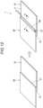
Fig. 12 , a lapfillet weld joint 1 in which afirst metal plate 10 and asecond metal plate 20 are overlapped and anedge portion 21 of thesecond metal plate 20 and asurface 11 in the vicinity of anedge portion 12 of thefirst metal plate 10 are welded by aweld bead 30 will be described as an example. - The first cause is geometric stress concentration. As shown in
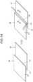
Fig. 13 , a boundary between theweld bead 30, which is a welded portion, and thefirst metal plate 10 and thesecond metal plate 20, which are metal members, is a discontinuous line, so that stress is concentrated on a toe of the weld bead. Magnitude of the stress concentration is inversely proportional to smoothness of the toe of the weld bead. - The second cause is deterioration of the material. The
first metal plate 10 and thesecond metal plate 20 are subjected to rapid heating and rapid cooling to form a heat-affectedportion 31 whose crystal structure is changed from an original material. Accordingly, material characteristics such as hardness, toughness, and elongation are locally changed in the heat-affectedportion 31. - The third cause is tensile residual stress. In addition to a series of heat hysteresis of a temperature rise and a temperature fall, the tensile residual stress generally remains in the vicinity of the welded portion after cooling is performed at room temperature due to a constraint around the welded portion. The tensile residual stress is considered to be a factor of a decrease in the fatigue strength.
- The geometric stress concentration, the local material deterioration, and the tensile residual stress are superimposed to deteriorate the joint fatigue characteristics.
- In view of such a background, various efforts and studies have been made to improve the fatigue strength of the weld joint from the related art in consideration of a mechanism thereof. For example, in
Patent Literature 1, a part of a material is locally reduced in thickness for the purpose of separating a stress concentration portion from a weld bead. In Patent Literatures 2 and 3, various peening treatments are performed after arc welding, and compressive residual stress is applied to a stress concentration portion. In Patent Literature 4, a welding material having a special composition is adopted, and a compressive stress is applied by utilizing martensite transformation. In Patent Literatures 5 and 6, after the end of welding, the periphery of a toe is subjected to a heat treatment again using a heat source such as a plasma arc or a laser. In Patent Literatures 7 and 8, another weld metal called a stiffening bead is provided. In Patent Literature 9, a convex press bead is provided adjacent to a weld bead. Further, a method has been proposed in which a toe is smoothly formed by a grinder grinding means, or a product itself is put into a furnace and annealed to reduce tensile residual stress. -
- Patent Literature 1:
JP2018-30169A - Patent Literature 2:
JP5880260B - Patent Literature 3:
JP3899007B - Patent Literature 4:
JP5450293B - Patent Literature 5:
JP2014-4609A - Patent Literature 6:
JP6515299B - Patent Literature 7:
JP5522317B - Patent Literature 8:
JP5843015B - Patent Literature 9:
JP6008072B - Meanwhile, in the case of a thin plate, there is another deterioration factor in addition to the above-described factors of the decrease in the fatigue strength. This is due to poor restraint of the metal member, distortion and deflection of the metal member itself, deterioration of plate alignment accuracy caused by thermal deformation generated at the time of welding, and the like, that is, enlargement of a root gap G which is a so-called gap between plates. When there is no root gap G, the maximum stress concentration portion on the
joint 1 is the toe of the weld bead. However, as shown inFigs. 14 and15 , when the root gap G is generated, the toe does not necessarily become the maximum stress concentration portion due to the rigidity deterioration, and the root gap G portion becomes the maximum stress concentration portion, and fracture is more likely to occur at an earlier stage. The means for improving joint fatigue strength described inPatent Literatures 1 to 9, which have been devised in various ways so far, do not have an effect of suppressing an increase in the root gap G, and thus there is room for further improvement. - The present invention has been made in view of the above-described problems, and an object thereof is to provide a lap fillet weld joint and a production method thereof capable of effectively improving fatigue strength with a simple structure.
- Accordingly, the above object of the present invention is achieved by the following configuration (1) according to a lap fillet weld joint.
- (1) A lap fillet weld joint produced by overlapping and welding a first metal plate and a second metal plate,
- the first metal plate has at least one bulging portion on an edge portion on one side which is a side welded to the second metal plate, the bulging portion extending along a length direction from the edge portion on the one side toward an edge portion on the other side of the first metal plate, and bulging in a direction facing the second metal plate with respect to a flat plate portion,
- the second metal plate has at least one protruding portion on an edge portion on one side which is a side welded to the first metal plate, the protruding portion protruding in a direction from an edge portion on the other side of the second metal plate toward the edge portion on the one side, and being capable of being inserted into the bulging portion,
- the lap fillet weld joint comprises a first weld bead formed by welding the first metal plate and the edge portion of the second metal plate on the one side of the second metal plate in a state where the protruding portion is inserted into the bulging portion, and
- the bulging portion is formed such that a height of the first metal plate in a plate thickness direction is equal to or greater than a sum of a plate thickness of the first metal plate and a plate thickness of the second metal plate, and a length of the first metal plate in the length direction exceeds a sum of a leg length of the first weld bead between the first metal plate and the second metal plate and a length of a weld heat-affected zone extending from the first weld bead to the other side of the first metal plate.
- According to this configuration, with a simple structure, stress concentration in the welded portion is alleviated, and the welded portion in which a root gap is suppressed is formed, so that joint fatigue strength can be effectively improved.
- Further, a preferred embodiment of the present invention related to the lap fillet weld joint relates to the following (2) to (8).
- (2) In the lap fillet weld joint according to the above (1), in the second metal plate, the protruding portion is formed between a pair of cutouts that is formed along the length direction from the edge portion on the one side of the second metal plate.
- According to the configuration, the protruding portion can be easily formed by providing the cutouts.
- (3) In the lap fillet weld joint according to the above (1) or (2), the bulging portion is formed by press molding.
- According to this configuration, the bulging portion can be formed accurately and easily.
- (4) The the lap fillet weld joint according to any one of the above (1) to (3), further comprising a second weld bead formed by welding the second metal plate and the edge portion of the first metal plate on the one side of the first metal plate at a position corresponding to the bulging portion.
- According to this configuration, the fatigue strength of the lap fillet weld joint can be further improved.
- (5) In the lap fillet weld joint according to the above (4), the first weld bead and the second weld bead are continuously formed.
- According to this configuration, welding operation of the first weld bead and the second weld bead is facilitated.
- (6) In the lap fillet weld joint according to any one of the above (1) to (5), the first metal plate has at least one cutout portion in the edge portion on the one side of the first metal plate, and the bulging portion is formed at a position corresponding to the cutout portion.
- According to this configuration, an overlapping area between the first metal plate and the second metal plate can be increased, and the fatigue strength is further improved.
- (7) In the lap fillet weld joint according to any one of the above (1) to (6), the height of the first metal plate in the plate thickness direction in an internal space formed by the bulging portion is substantially equal to a sum of the plate thickness of the first metal plate and the plate thickness of the second metal plate.
- According to this configuration, an effect of suppressing the root gap is further improved.
- (8) In the lap fillet weld joint according to any one of the above (1) to (7), the bulging portion is formed such that the height of the first metal plate in the plate thickness direction gradually decreases from an inlet side of the protruding portion toward the edge portion of the first metal plate on the other side of the first metal plate.
- According to this configuration, the first metal plate and the second metal plate can be restrained without loosening while the protruding portion is easily inserted into the bulging portion.
- The above object of the present invention is achieved by the following configuration (9) related to a member with a closed cross section.
- (9) A member with a closed cross section to which the lap fillet weld joint according to any one of the above (1) to (8) is applied.
- According to this configuration, the member with a closed cross section having improved joint fatigue strength can be produced.
- The above object of the present invention is achieved by the following configuration (10) related to a production method of a lap fillet weld joint.
- (10) A production method of a lap fillet weld j oint produced by overlapping and welding a first metal plate and a second metal plate, comprising:
- a step of forming at least one bulging portion on an edge portion of the first metal plate on one side of the first metal plate, which is a side to be welded to the second metal plate, the bulging portion extending along a length direction from the edge portion on the one side toward an edge portion on the other side of the first metal plate, and bulging in a direction facing the second metal plate with respect to a flat plate portion;
- a step of forming at least one protruding portion on an edge portion of the second metal plate on one side of the second metal plate, which is a side to be welded to the first metal plate, the protruding portion protruding in a direction from an edge portion on the other side of the second metal plate toward the edge portion on the one side, and being capable of being inserted into the bulging portion;
- a step of overlapping the first metal plate with the second metal plate while inserting the protruding portion into the bulging portion; and
- a step of forming a first weld bead by welding the first metal plate and the edge portion of the second metal plate on the one side of the second metal plate, and
- the bulging portion is formed such that a height of the first metal plate in a plate thickness direction is equal to or greater than a sum of a plate thickness of the first metal plate and a plate thickness of the second metal plate, and a length of the first metal plate in the length direction exceeds a sum of a leg length of the first weld bead between the first metal plate and the second metal plate and a length of a weld heat-affected zone extending from the first weld bead to the other side of the first metal plate.
- According to this configuration, with a simple structure, stress concentration in the welded portion is alleviated, and the welded portion in which a root gap is suppressed is formed, so that joint fatigue strength can be effectively improved.
- Further, a preferred embodiment of the present invention related to the production method of a lap fillet weld joint relates to the following (11) to (16).
- (11) In the production method of a lap fillet weld j oint according to the above (10), in the second metal plate, the protruding portion is formed between a pair of cutouts that is formed along the length direction from the edge portion on the one side of the second metal plate.
- According to the configuration, the protruding portion can be easily formed by providing the cutouts.
- (12) In the production method of a lap fillet weld joint according to the above (10) or (11), the bulging portion is formed by press molding.
- According to this configuration, the bulging portion can be formed accurately and easily.
- (13) In the production method of a lap fillet weld joint according to any one of the above (10) to (12), the step of forming the first weld bead is performed by any one of an arc welding method, a laser welding method, and a laser arc hybrid welding method.
- According to this configuration, the joint fatigue strength can be effectively improved by any one of the welding methods.
- (14) The production method of a lap fillet weld joint according to any one of the above (10) to (13) further includes: a step of forming a second weld bead by welding the second metal plate and the edge portion of the first metal plate on the one side of the first metal plate at a position corresponding to the bulging portion.
- According to this configuration, the fatigue strength of the lap fillet weld joint can be further improved.
- (15) In the production method of a lap fillet weld joint according to the above (14), the first weld bead and the second weld bead are formed by continuous welding.
- According to this configuration, welding operation of the first weld bead and the second weld bead is facilitated.
- (16) The production method of a lap fillet weld joint according to any one of the above (10) to (15) further includes: a step of forming at least one cutout portion in the edge portion of the first metal plate on the one side of the first metal plate before forming the bulging portion on the first metal plate, and the bulging portion is formed at a position corresponding to the cutout portion.
- According to this configuration, an overlapping area between the first metal plate and the second metal plate can be increased, and the fatigue strength is further improved.
- According to the lap fillet weld j oint and the production method of a lap fillet weld joint of the present invention, with a simple structure, the stress concentration in the welded portion is alleviated, and the welded portion in which the root gap is suppressed is formed, so that the joint fatigue strength can be effectively improved.
-
- [
Fig. 1] Fig. 1 is a perspective view showing a lap fillet weld joint according to a first embodiment of the present invention. - [
Fig. 2] Fig. 2 is a perspective view showing production steps of the lap fillet weld joint shown inFig. 1 . - [
Fig. 3] Fig. 3 is a cross-sectional view taken along a line C-C of the lap fillet weld joint shown inFig. 2 . - [
Fig. 4] Fig. 4 is a cross-sectional view taken along a line D-D of a first metal plate shown inFig. 1 . - [
Fig. 5] Fig. 5 is a perspective view of a lap fillet weld joint according to a first modification of the first embodiment. - [
Fig. 6] Fig. 6 is a perspective view of a lap fillet weld joint according to a second modification of the first embodiment. - [
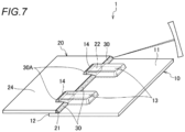
Fig. 7] Fig. 7 is a perspective view of a lap fillet weld joint according to a third modification of the first embodiment. - [
Fig. 8] Fig. 8 is a perspective view showing production steps of a lap fillet weld joint according to a second embodiment of the present invention. - [
Fig. 9] Fig. 9 is a perspective view showing production steps of a lap fillet weld joint according to a first modification of the second embodiment. - [
Fig. 10] Fig. 10 is a perspective view of a suspension arm that is an example of the lap fillet weld joint of the present invention. - [
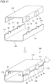
Fig. 11] Fig. 11 is a perspective view schematically showing a cross section taken along a line E-E ofFig. 10 . - [
Fig. 12] Fig. 12 is a perspective view of a lap fillet weld joint in related art produced by overlapping and welding two metal plates. - [
Fig. 13 ]Fig. 3 is a cross-sectional view taken along a line A-A of the lap fillet weld joint shown inFig. 12 . - [
Fig. 14] Fig. 14 is a perspective view of a lap fillet weld joint in related art having a gap. - [
Fig. 15] Fig. 15 is a cross-sectional view taken along a line B-B of the lap fillet weld joint shown inFig. 14 . - Hereinafter, embodiments of a lap fillet weld j oint according to the present invention will be described with reference to the drawings.
-
Fig. 1 is a perspective view showing a lap fillet weld joint according to a first embodiment of the present invention,Fig. 2 is a perspective view showing production steps of the lap fillet weld joint ofFig. 1 , andFig. 3 is a cross-sectional view taken along a line C-C of the lap fillet weld joint ofFig. 2 . As shown inFigs. 2 and3 , a lap fillet weld joint 1 according to the first embodiment of the present invention has a configuration in which afirst metal plate 10 and asecond metal plate 20 are overlapped with each other, and asecond edge portion 21 of thesecond metal plate 20 is welded to thefirst metal plate 10. - In the following description, a side of the
first metal plate 10 welded to thesecond metal plate 20 is referred to as one side, an opposite side is referred to as the other side, and an edge portion on the one side of thefirst metal plate 10 is referred to as afirst edge portion 12. Further, a side of thesecond metal plate 20 welded to thefirst metal plate 10 is referred to as one side, an opposite side is referred to as the other side, and an edge portion on one side of thesecond metal plate 20 is referred to as thesecond edge portion 21. That is, thefirst edge portion 12 and thesecond edge portion 21 face each other, and the one side and the other side of thefirst metal plate 10 and thesecond metal plate 20 are opposite to each other. - Further, in the present embodiment, the first and
second metal plates second metal plates edge portions 12, 21) is also referred to as a width direction, and a direction separating from the welding line is also referred to as a length direction. - In the
first metal plate 10, a plurality of bulgingportions 13 bulging in a direction (surface side) facing thesecond metal plate 20 with respect to a planar plate portion and forming internal spaces S on a back surface side are formed at thefirst edge portion 12, which is a side welded to thesecond metal plate 20, in a way of being spaced from each other along theedge portion 12. For example, in the embodiment shown inFig. 1 , two bulgingportions 13 are provided. A height Xt of the bulgingportion 13 in a plate thickness direction of thefirst metal plate 10 is set to be equal to or greater than ta + tb, which is the sum of a plate thickness ta of thefirst metal plate 10 and a plate thickness tb of thesecond metal plate 20. A length XL in a length direction of thefirst metal plate 10 is set to a length exceeding L1 + L2, which is the sum of a leg length L1 of afirst weld bead 30 between thefirst metal plate 10 and thesecond metal plate 20 and a length L2 of a weld heat-affectedzone 31 extending from thefirst weld bead 30 to the other side of the first metal plate 10 (seeFig. 13 ). - On the other hand, the
second metal plate 20 includes a plurality of protrudingportions 22 that are formed bycutouts 23 provided in thesecond edge portion 21 that is a side welded to thefirst metal plate 10 and protrude from thesecond edge portion 21 toward thefirst metal plate 10. For example, in the embodiment shown inFig. 1 , two protrudingportions 22 are provided. The two protrudingportions 22 are formed so as to correspond to intervals of the two bulgingportions 13, and can be inserted into the internal spaces S of the bulgingportions 13. - The bulging
portion 13 of thefirst metal plate 10 can be easily and accurately formed by cold or hot pressing thefirst metal plate 10. - Then, the protruding
portion 22 of thesecond metal plate 20 is inserted into the internal space S of the bulgingportion 13 of thefirst metal plate 10, and thefirst metal plate 10 and thesecond metal plate 20 are overlapped with each other. Accordingly, a surface of the protrudingportion 22 of thesecond metal plate 20 comes into contact with a back surface of the bulgingportion 13, and a portion of a back surface of thesecond metal plate 20 on a side of thesecond edge portion 21 excluding the protrudingportion 22 comes into contact with asurface 11 of thefirst metal plate 10, so that thesecond metal plate 20 is held by thefirst metal plate 10. - The height Xt in the thickness direction of the
first metal plate 10 in the internal space S is preferably substantially equal to the sum of the plate thickness ta of thefirst metal plate 10 and the plate thickness tb of thesecond metal plate 20. However, since there is a possibility that the protrudingportion 22 does not enter the internal space S of the bulgingportion 13 if the height Xt is completely equal to the sum of the plate thickness ta and the plate thickness tb, a slight margin is actually provided. However, in this case, it is also desirable that at least a part of the surface of the protrudingportion 22 of thesecond metal plate 20 is physically in contact with the back surface of the bulgingportion 13, and thus the root gap G between thefirst metal plate 10 and thesecond metal plate 20 is suppressed to the minimum gap. - Further, in this embodiment, the surface of the protruding
portion 22 of thesecond metal plate 20 and the back surface of the bulgingportion 13 are substantially parallel to each other, but the bulgingportion 13 may be gently inclined such that the height thereof gradually decreases from an inlet side of the protrudingportion 22 toward aroot portion 40 side (an edge portion on the other side of the first metal plate 10) to be described later. Specifically, in the bulgingportion 13, the height Xt of an inlet side opening of the protrudingportion 22 is set to be equal to or greater than ta + tb, which is the sum of the plate thickness ta of thefirst metal plate 10 and the plate thickness tb of thesecond metal plate 20, and the height Xt of the bulgingportion 13 is set to be less than ta + tb, which is the sum of the plate thickness ta of thefirst metal plate 10 and the plate thickness tb of thesecond metal plate 20, in a region where the bulgingportion 13 and the protrudingportion 22 are overlapped with each other in the length direction of thefirst metal plate 10. Such a bulgingportion 13 facilitates insertion of the protrudingportion 22 into the bulgingportion 13, and at the same time, the protrudingportion 22 is pushed into the bulgingportion 13 to abut on the bulgingportion 13, so that thefirst metal plate 10 and thesecond metal plate 20 can be restrained without loosening. - Next, in a state where the protruding
portion 22 is inserted into the bulgingportion 13, a part of thesecond edge portion 21 of thesecond metal plate 20 and a part of thesurface 11 of thefirst metal plate 10 are welded by arc welding or laser arc hybrid welding to form thefirst weld bead 30. Here, the welded part is thesecond edge portion 21 of thesecond metal plate 20 exposed on thesurface 11 of thefirst metal plate 10, and thesecond edge portion 21 of the protrudingportion 22 inserted into the bulgingportion 13 is not welded. Thefirst weld bead 30 may be formed in contact with anouter side surface 41 of the bulgingportion 13 extending from thefirst edge portion 12 of the bulgingportion 13 toward the other side. - In the
weld joint 1 of the present embodiment, when a load in the plate thickness direction acts on the weld joint 1, aroot portion 40 on the side spaced from thefirst edge portion 12 of the bulgingportion 13 becomes a part of a stress concentration portion, so that stress concentration can be alleviated from thefirst weld bead 30 which is a weld portion. Therefore, the stress concentration does not act on the weld heat-affected zone 31 (seeFig. 13 ) where strength is decreased due to an influence of welding heat, and base metal strength of thefirst metal plate 10 and thesecond metal plate 20 is maintained. - Accordingly, since the
root portion 40 serving as the stress concentration portion is separated from thefirst weld bead 30, the influence of the weld heat-affectedzone 31, where the strength is decreased due to the welding heat, on a fatigue strength of the lap fillet weld joint 1 is small, and the strength of thefirst metal plate 10 and thesecond metal plate 20, which are the base metal, is maintained. - As in the present embodiment, when the bulging
portion 13 of thefirst metal plate 10 and theedge portion 21 of thesecond metal plate 20 are overlapped with each other by thecutouts 23 formed in the rectangularsecond metal plate 20 to make thefirst metal plate 10 and thesecond metal plate 20 overlap with each other, it is preferable that the length XL of the bulgingportion 13 in the length direction of thefirst metal plate 10 also takes into consideration a length L3 of the overlapping portion of thefirst metal plate 10 and thesecond metal plate 20. That is, in the present embodiment, in the bulgingportion 13, the length XL in the length direction of thefirst metal plate 10 is set to a length exceeding the sum L1 + L2 + L3 of the leg length L1 of thefirst weld bead 30 between thefirst metal plate 10 and thesecond metal plate 20, the length L2 of the weld heat-affectedzone 31 extending from thefirst weld bead 30 to the other side of thefirst metal plate 10, and the length L3 of the overlapping portion of thefirst metal plate 10 and thesecond metal plate 20. - Further, the gap G between the
first metal plate 10 and thesecond metal plate 20 is suppressed to the minimum gap without using a clamp jig or the like commonly used for suppressing the gap G between the plates, and the fatigue strength of the weld joint 1 is improved. It should be noted that the larger the number of clamp jigs, the higher the effect of suppressing the gap G, but when the number of clamp jigs increases, the number of setting steps and the jig cost increase, which is not preferable. - Further, by appropriately setting the length XL of the single bulging
portion 13, a width XW of the single bulgingportion 13, a ratio (ΣXb2/ΣB) of a total length (ΣXW) of the widths XW of the bulgingportions 13 to a total length (ΣB; ΣB = B1 + B2 + B3 in the example shown inFig. 1 ) of thefirst weld bead 30, and the radius Xr of theroot portion 40 of the bulgingportion 13 as shown inFig. 4 , the strength can be optimized. Since the bulgingportion 13 is formed by press working (press molding), the radius Xr of theroot portion 40 of the bulgingportion 13 can be formed in a smooth shape stably. - As described above, according to the lap
fillet weld joint 1 of the present embodiment, since the gap G between thefirst metal plate 10 and thesecond metal plate 20 can be suppressed, welding performance is stabilized. Further, a shape of the bulgingportion 13 formed by the press working is not damaged by welding, and fatigue resistance is improved. - In the present embodiment, a tip end portion of the protruding
portion 22 of thesecond metal plate 20 protrudes from thesecond edge portion 21 from the viewpoint of joint rigidity, but the present invention is not limited thereto, and the tip end portion of the protrudingportion 22 may be located at the same position as thesecond edge portion 21 in the length direction. -
Fig. 5 is a perspective view of a lap fillet weld joint of a first modification of the first embodiment, in which thesecond edge portion 21 of thesecond metal plate 20 and thesurface 11 of thefirst metal plate 10 are welded by laser welding to form thefirst weld bead 30. At the time of laser welding, a filler wire may be separately used. - Next, lap fillet weld joints of a second modification and a third modification of the first embodiment will be described with reference to
Figs. 6 and7 .
In theweld joint 1 of the second modification, as shown inFig. 6 , the protrudingportions 22 of thesecond metal plate 20 are inserted into and fitted to the bulgingportions 13 of thefirst metal plate 10, and thesecond edge portion 21 of thesecond metal plate 20 and thesurface 11 of thefirst metal plate 10 are welded by arc welding or laser arc hybrid welding to form thefirst weld bead 30. Further,first edge portions 14 of the bulgingportions 13 and asurface 24 of thesecond metal plate 20 are welded by the arc welding or the laser arc hybrid welding to formsecond weld beads 30A. Thefirst weld bead 30 and thesecond weld bead 30A may be welded continuously. Accordingly, the number of welding steps is reduced as compared with a case where thefirst weld bead 30 and thesecond weld bead 30A are welded in separate steps. - In the lap
fillet weld joint 1 of the third modification, as shown inFig. 7 , the protrudingportions 22 of thesecond metal plate 20 are inserted into and fitted to the bulgingportions 13 of thefirst metal plate 10, thesecond edge portion 21 of thesecond metal plate 20 and thesurface 11 of thefirst metal plate 10 are laser-welded to form thefirst weld bead 30, and thefirst edge portions 14 of the bulgingportions 13 and thesurface 24 of thesecond metal plate 20 are laser-welded to form thesecond weld beads 30A. Thefirst weld bead 30 and thesecond weld bead 30A may be welded continuously by the laser welding. -
Fig. 8 is a perspective view showing production steps of a lap fillet weld joint according to a second embodiment of the present invention. As shown inFig. 8 , in thefirst edge portion 12 of thefirst metal plate 10 of the second embodiment, a plurality ofcutout portions 15 are formed along thefirst edge portion 12. For example, in the embodiment shown inFig. 8 , twocutout portions 15 are provided. The bulgingportions 13 are formed at thecutout portions 15, respectively. - Similarly to the
first metal plate 10 of the first embodiment, the bulgingportion 13 has the internal space S in which the height Xt in the plate thickness direction of thefirst metal plate 10 is equal to or greater than ta + tb, which is the sum of the plate thickness ta of thefirst metal plate 10 and the plate thickness tb of thesecond metal plate 20, and a length in the direction from thefirst edge portion 12 toward the other side is the length XL (seeFig. 2 ). The length XL exceeds L1 + L2, which is the sum of the leg length L1 of thefirst weld bead 30 between thefirst metal plate 10 and thesecond metal plate 20 and the length L2 of the weld heat-affectedzone 31 extending from thefirst weld bead 30 to the other side of the first metal plate 10 (seeFig. 13 ). - On the other hand, the
second metal plate 20 has the plurality of protrudingportions 22 protruding in the direction of thefirst metal plate 10 from thesecond edge portion 21 which is a side welded to thefirst metal plate 10. The protrudingportion 22 is formed so as to correspond to the intervals of the bulgingportions 13, and can be inserted into the internal space S of the bulgingportion 13. - Then, the protruding
portion 22 of thesecond metal plate 20 is inserted into and fitted to the bulgingportion 13 of thefirst metal plate 10, and thefirst metal plate 10 and thesecond metal plate 20 are overlapped with each other. Accordingly, a surface of the protrudingportion 22 of thesecond metal plate 20 comes into contact with a back surface of the bulgingportion 13, and a portion of a back surface of thesecond metal plate 20 on thesecond edge portion 21 side excluding the protrudingportion 22 comes into contact with thesurface 11 of thefirst metal plate 10, so that thesecond metal plate 20 is held by thefirst metal plate 10. Accordingly, the gap G between thefirst metal plate 10 and thesecond metal plate 20 is suppressed to the minimum gap. - Next, a part of the
edge portion 21 of thesecond metal plate 20 and a part of thesurface 11 of thefirst metal plate 10 are welded by any one of arc welding, laser welding, and laser arc hybrid welding to form thefirst weld bead 30. Further, thesecond weld bead 30A may be formed by welding thefirst edge portion 14 of the bulgingportion 13 and thesurface 24 of thesecond metal plate 20 by any one of the arc welding, the laser welding, and the laser arc hybrid welding. -
Fig. 9 is a perspective view showing production steps of a lap fillet weld joint according to a first modification of the second embodiment. In the present modification, thecutout portion 15 formed along thefirst edge portion 12 of thefirst metal plate 10 has corner portions each formed in an R shape, and each of the bulgingportions 13 is formed at thecutout portion 15. - The bulging
portion 13 has the internal space S having the same size as that of thefirst metal plate 10 of the second embodiment. That is, the bulgingportion 13 has the internal space S in which the height Xt in the plate thickness direction of thefirst metal plate 10 is equal to or greater than ta + tb, which is the sum of the plate thickness ta of thefirst metal plate 10 and the plate thickness tb of thesecond metal plate 20, and a length in the direction from thefirst edge portion 12 toward the other side is the length XL. - On the other hand, in the
second metal plate 20, the plurality of protrudingportions 22 protruding in the direction of thefirst metal plate 10 are formed at thesecond edge portion 21 with which thefirst metal plate 10 is overlapped, corresponding to the intervals of the bulgingportions 13. The shape of the protrudingportion 22 is an R shape. - Then, the protruding
portion 22 of thesecond metal plate 20 is inserted into and fitted to the bulgingportion 13 of thefirst metal plate 10, thefirst metal plate 10 and thesecond metal plate 20 are overlapped with each other, and thesecond edge portion 21 of thesecond metal plate 20 and thesurface 11 of thefirst metal plate 10 are welded by any one of the arc welding, the laser welding, and the laser arc hybrid welding to form thefirst weld bead 30. - By forming the
cutout portion 15 of thefirst metal plate 10 and the protrudingportion 22 of thesecond metal plate 20 in the R shape, an overlapping area between thefirst metal plate 10 and thesecond metal plate 20 can be increased, and joining strength is improved. -
Fig. 10 is a perspective view of asuspension arm 100 which is an example of the lap fillet weld joint 1 described above, andFig. 11 is a perspective view schematically showing a cross section taken along a line E-E ofFig. 10 . In thesuspension arm 100, afirst member 110 and asecond member 120 each formed in a substantially bowl shape are abutted on each other, and a joint surface thereof is welded by any one of the arc welding, the laser welding, and the laser arc hybrid welding. - As shown in
Fig. 11 , each of thefirst member 110 and thesecond member 120 is formed in a substantially gutter shape whose cross section is curved inward, and erectedportions 111 are provided at both end portions in the width direction of thefirst member 110, and erectedportions 121 are provided at both end portions in the width direction of thesecond member 120 so as to correspond to the erectedportions 111. In each of the erectedportions 111 of thefirst member 110, the plurality of bulgingportions 13 described in the first embodiment (seeFig. 1 ) is formed so as to be spaced from each other in the length direction. Further, the plurality of protrudingportions 22 described in the first embodiment (seeFig. 1 ) is formed at each erectedportion 121 of thesecond member 120 so as to correspond to the intervals of the bulgingportions 13. - Then, after the protruding
portion 22 of thesecond member 120 is inserted into the bulgingportion 13 of thefirst member 110 and the end portions of the erectedportion 111 and the erectedportion 121 are overlapped with each other, theedge portion 114 of thesecond member 120 and the erectedportion 111 of thefirst member 110 are welded to each other by any one of the arc welding, the laser welding, and the laser arc hybrid welding to form thefirst weld bead 30. Further, although not shown, thesecond weld bead 30A may be formed by welding thefirst edge portion 14 of the bulgingportion 13 and thesecond member 120 by any one of the arc welding, the laser welding, and the laser arc hybrid welding. - Accordingly, the lap fillet weld joint 1 is also applied to a hollow member with a closed cross section having any shape, light weight, and high fatigue resistance strength.
- Note that the present invention is not limited to the above-described embodiments and modifications, and modifications, improvements, and the like can be made as appropriate.
- For example, in the above-described embodiment, any one of the arc welding, the laser welding, and the laser arc hybrid welding is described as a joining method, but the joining method is not limited thereto, and brazing or the like can also be used. In this case, different materials can also be joined to each other.
- Further, in the above-described embodiment, the second metal plate is provided with the protruding portion by providing the cutout in the edge portion on one side thereof, but for example, the edge portion on the one side may be formed in a corrugated shape in which a concave portion and a convex portion are continuous, and the convex portion may be formed as the protruding portion.
- Further, according to the present invention, the root gap can be suppressed as long as the second metal plate is held by the first metal plate by bringing the back surface of the second metal plate on a second edge portion side into contact with the surface of the first metal plate and bringing at least one back surface of the plurality of bulging portions into contact with at least one surface of the plurality of protruding portions of the second metal plate.
- Although various embodiments have been described above with reference to the drawings, it is needless to say that the present invention is not limited to such examples. It will be apparent to those skilled in the art that various changes and modifications can be conceived within the scope of the claims, and it is also understood that the various changes and modifications belong to the technical scope of the present invention. In addition, components in the embodiments described above may be combined freely within a range not departing from the spirit of the invention.
- The present application is based on Japanese Patent Application filed on July 15, 2020 (
Japanese Patent Application No. 2020-121667 -
- 1 lap fillet weld joint
- 10 first metal plate
- 12 first edge portion (edge portion on one side of first metal plate)
- 13 bulging portion
- 15 cutout portion
- 20 second metal plate
- 21 second edge portion (edge portion on one side of second metal plate, end surface)
- 22 protruding portion
- 23 cutout
- 30 first weld bead
- 30A second weld bead
- 31 weld heat-affected zone
- 100 suspension arm (member with closed cross section)
- L1 leg length of weld bead
- L2 length of weld heat-affected zone
- S internal space
- ta plate thickness of first metal plate
- tb plate thickness of second metal plate
- XL length of bulging portion (length in direction from edge portion on one side toward edge portion on the other side of first metal plate)
- Xt height of bulging portion in plate thickness direction (height in plate thickness direction of first metal plate)
- XW width of bulging portion
Claims (21)
- A lap fillet weld joint produced by overlapping and welding a first metal plate and a second metal plate,wherein the first metal plate has at least one bulging portion on an edge portion on one side which is a side welded to the second metal plate, the bulging portion extending along a length direction from the edge portion on the one side toward an edge portion on the other side of the first metal plate, and bulging in a direction facing the second metal plate with respect to a flat plate portion,wherein the second metal plate has at least one protruding portion on an edge portion on one side which is a side welded to the first metal plate, the protruding portion protruding in a direction from an edge portion on the other side of the second metal plate toward the edge portion on the one side, and being capable of being inserted into the bulging portion,wherein the lap fillet weld joint comprises a first weld bead formed by welding the first metal plate and the edge portion of the second metal plate on the one side of the second metal plate in a state where the protruding portion is inserted into the bulging portion, andwherein the bulging portion is formed such that a height of the first metal plate in a plate thickness direction is equal to or greater than a sum of a plate thickness of the first metal plate and a plate thickness of the second metal plate, and a length of the first metal plate in the length direction exceeds a sum of a leg length of the first weld bead between the first metal plate and the second metal plate and a length of a weld heat-affected zone extending from the first weld bead to the other side of the first metal plate.
- The lap fillet weld joint according to claim 1,
wherein in the second metal plate, the protruding portion is formed between a pair of cutouts that is formed along the length direction from the edge portion on the one side of the second metal plate. - The lap fillet weld j oint according to claim 1,
wherein the bulging portion is formed by press molding. - The lap fillet weld joint according to claim 2,
wherein the bulging portion is formed by press molding. - The lap fillet weld joint according to any one of claims 1 to 4, further comprising:
a second weld bead formed by welding the second metal plate and the edge portion of the first metal plate on the one side of the first metal plate at a position corresponding to the bulging portion. - The lap fillet weld joint according to claim 5,
wherein the first weld bead and the second weld bead are continuously formed. - The lap fillet weld joint according to any one of claims 1 to 4,wherein the first metal plate has at least one cutout portion in the edge portion on the one side of the first metal plate, andwherein the bulging portion is formed at a position corresponding to the cutout portion.
- The lap fillet weld joint according to claim 5,wherein the first metal plate has at least one cutout portion in the edge portion on the one side of the first metal plate, andwherein the bulging portion is formed at a position corresponding to the cutout portion.
- The lap fillet weld joint according to claim 6,wherein the first metal plate has at least one cutout portion in the edge portion on the one side of the first metal plate, andwherein the bulging portion is formed at a position corresponding to the cutout portion.
- The lap fillet weld joint according to any one of claims 1 to 4,
wherein the height of the first metal plate in the plate thickness direction in an internal space formed by the bulging portion is substantially equal to a sum of the plate thickness of the first metal plate and the plate thickness of the second metal plate. - The lap fillet weld joint according to any one of claims 1 to 4,
wherein the bulging portion is formed such that the height of the first metal plate in the plate thickness direction gradually decreases from an inlet side of the protruding portion toward the edge portion of the first metal plate on the other side of the first metal plate. - A member with a closed cross section to which the lap fillet weld joint according to any one of claims 1 to 4 is applied.
- A production method of a lap fillet weld joint produced by overlapping and welding a first metal plate and a second metal plate, comprising:a step of forming at least one bulging portion on an edge portion of the first metal plate on one side of the first metal plate, which is a side to be welded to the second metal plate, the bulging portion extending along a length direction from the edge portion on the one side toward an edge portion on the other side of the first metal plate, and bulging in a direction facing the second metal plate with respect to a flat plate portion;a step of forming at least one protruding portion on an edge portion of the second metal plate on one side of the second metal plate, which is a side to be welded to the first metal plate, the protruding portion protruding in a direction from an edge portion on the other side of the second metal plate toward the edge portion on the one side, and being capable of being inserted into the bulging portion;a step of overlapping the first metal plate with the second metal plate while inserting the protruding portion into the bulging portion; anda step of forming a first weld bead by welding the first metal plate and the edge portion of the second metal plate on the one side of the second metal plate,wherein the bulging portion is formed such that a height of the first metal plate in a plate thickness direction is equal to or greater than a sum of a plate thickness of the first metal plate and a plate thickness of the second metal plate, and a length of the first metal plate in the length direction exceeds a sum of a leg length of the first weld bead between the first metal plate and the second metal plate and a length of a weld heat-affected zone extending from the first weld bead to the other side of the first metal plate.
- The production method of a lap fillet weld joint according to claim 13,
wherein in the second metal plate, the protruding portion is formed between a pair of cutouts that is formed along the length direction from the edge portion on the one side of the second metal plate. - The production method of a lap fillet weld joint according to claim 13,
wherein the bulging portion is formed by press molding. - The production method of a lap fillet weld joint according to claim 13,
wherein the step of forming the first weld bead is performed by any one of an arc welding method, a laser welding method, and a laser arc hybrid welding method. - The production method of a lap fillet weld joint according to any one of claims 13 to 16, further comprising:
a step of forming a second weld bead by welding the second metal plate and the edge portion of the first metal plate on the one side of the first metal plate at a position corresponding to the bulging portion. - The production method of a lap fillet weld joint according to claim 17,
wherein the first weld bead and the second weld bead are formed by continuous welding. - The production method of a lap fillet weld joint according to any one of claims 13 to 16, further comprising:a step of forming at least one cutout portion in the edge portion of the first metal plate on the one side of the first metal plate before forming the bulging portion on the first metal plate,wherein the bulging portion is formed at a position corresponding to the cutout portion.
- The production method of a lap fillet weld joint according to claim 17, further comprising:a step of forming at least one cutout portion in the edge portion of the first metal plate on the one side of the first metal plate before forming the bulging portion on the first metal plate,wherein the bulging portion is formed at a position corresponding to the cutout portion.
- The production method of a lap fillet weld j oint according to claim 18, further comprising:a step of forming at least one cutout portion in the edge portion of the first metal plate on the one side of the first metal plate before forming the bulging portion on the first metal plate,wherein the bulging portion is formed at a position corresponding to the cutout portion.
Applications Claiming Priority (2)
| Application Number | Priority Date | Filing Date | Title |
|---|---|---|---|
| JP2020121667A JP7328181B2 (en) | 2020-07-15 | 2020-07-15 | LAP FILLET WELD JOINT, MANUFACTURING METHOD THEREOF, AND CLOSED SECTION MEMBER |
| PCT/JP2021/025944 WO2022014489A1 (en) | 2020-07-15 | 2021-07-09 | Lap fillet weld joint, production method thereof and member with closed cross section |
Publications (3)
| Publication Number | Publication Date |
|---|---|
| EP4166269A1 true EP4166269A1 (en) | 2023-04-19 |
| EP4166269A4 EP4166269A4 (en) | 2023-12-06 |
| EP4166269B1 EP4166269B1 (en) | 2025-09-24 |
Family
ID=79555445
Family Applications (1)
| Application Number | Title | Priority Date | Filing Date |
|---|---|---|---|
| EP21841286.4A Active EP4166269B1 (en) | 2020-07-15 | 2021-07-09 | Welded assembly comprising a first metal plate, a second metal plate and a lap fillet weld joint and associated production method |
Country Status (7)
| Country | Link |
|---|---|
| US (1) | US12523246B2 (en) |
| EP (1) | EP4166269B1 (en) |
| JP (1) | JP7328181B2 (en) |
| KR (1) | KR102690647B1 (en) |
| CN (1) | CN115943014B (en) |
| MX (1) | MX2023000631A (en) |
| WO (1) | WO2022014489A1 (en) |
Families Citing this family (2)
| Publication number | Priority date | Publication date | Assignee | Title |
|---|---|---|---|---|
| JP7810888B2 (en) * | 2022-04-01 | 2026-02-04 | 日本製鉄株式会社 | METAL MEMBER MANUFACTURING METHOD AND METAL MEMBER |
| CN117862823A (en) * | 2024-01-23 | 2024-04-12 | 浙江极氪智能科技有限公司 | Energy absorption box, energy absorption box welding process and vehicle |
Family Cites Families (34)
| Publication number | Priority date | Publication date | Assignee | Title |
|---|---|---|---|---|
| JPS5450293U (en) | 1977-09-14 | 1979-04-07 | ||
| JPS5837945Y2 (en) | 1978-07-27 | 1983-08-27 | 富士電子工業株式会社 | Rotating table type induction hardening equipment |
| JPS5843015U (en) | 1981-09-17 | 1983-03-23 | 三洋電機株式会社 | audio demodulation circuit |
| JPS5880260U (en) | 1981-11-24 | 1983-05-31 | 株式会社東芝 | Fire damper device |
| JPS608072U (en) | 1983-06-30 | 1985-01-21 | アルプス電気株式会社 | printer |
| JPS6061132A (en) | 1983-09-13 | 1985-04-08 | Hitachi Ltd | Plastic working device of metallic product |
| US5476210A (en) * | 1993-06-25 | 1995-12-19 | Fuji Jukogyo Kabushiki Kaisha | Structure for joining plate elements and method for joining the same |
| US5454480A (en) * | 1993-10-21 | 1995-10-03 | Morris Holmes & Co. | Flangeless fuel tank |
| DE19943752C1 (en) * | 1999-09-13 | 2001-05-31 | Bayerische Motoren Werke Ag | Joining point for laser-welded components |
| JP3899007B2 (en) | 2002-10-08 | 2007-03-28 | 新日本製鐵株式会社 | Method for improving fatigue strength of lap fillet welded joints |
| JP5267317B2 (en) * | 2008-12-09 | 2013-08-21 | 新日鐵住金株式会社 | Laser lap welded joint of high strength thin steel sheet and manufacturing method thereof |
| JP2011140051A (en) * | 2010-01-08 | 2011-07-21 | Mitsubishi Electric Corp | Welded joint and welding method of sheet metal |
| JP5450293B2 (en) | 2010-07-01 | 2014-03-26 | 株式会社神戸製鋼所 | Fillet welded joint and gas shielded arc welding method |
| CN201895178U (en) * | 2010-08-12 | 2011-07-13 | 湖北省电力勘测设计院 | Anti-cracking tooth type flange |
| JP5522317B2 (en) | 2012-04-17 | 2014-06-18 | 新日鐵住金株式会社 | Fillet arc welded joint and method for forming the same |
| JP5880260B2 (en) | 2012-04-26 | 2016-03-08 | 新日鐵住金株式会社 | Manufacturing method of welded structure |
| JP5985901B2 (en) | 2012-06-25 | 2016-09-06 | Jfeスチール株式会社 | Welded joint and method for forming the same |
| ES2658222T3 (en) | 2012-11-29 | 2018-03-08 | Nippon Steel & Sumitomo Metal Corporation | Method for forming an angle arc welding joint and an angle arc welding joint |
| JP6349888B2 (en) | 2014-04-04 | 2018-07-04 | 日産自動車株式会社 | Welded parts |
| JP6265089B2 (en) * | 2014-09-05 | 2018-01-24 | Jfeスチール株式会社 | Method for improving fatigue strength of automotive suspension parts |
| CA2962380C (en) * | 2014-10-03 | 2019-10-15 | Nippon Steel & Sumitomo Metal Corporation | Welded structure member and manufacturing method thereof |
| CN107249800B (en) | 2015-02-13 | 2019-02-01 | 新日铁住金株式会社 | Fillet welded joint and method of making the same |
| CN104858535A (en) * | 2015-05-18 | 2015-08-26 | 上海交通大学 | Connection method for improving strength of overlap joints |
| CN108025401B (en) | 2015-07-28 | 2020-08-04 | 日本制铁株式会社 | Arc fillet weld and method for manufacturing same |
| JP6065147B1 (en) * | 2015-10-26 | 2017-01-25 | Jfeスチール株式会社 | Joint structure of lap fillet arc welded joints and press-formed parts |
| JP6369448B2 (en) * | 2015-11-11 | 2018-08-08 | Jfeスチール株式会社 | Lap fillet arc welded joint, and automotive structural component having the lap fillet arc welded joint |
| FR3047912B1 (en) * | 2016-02-20 | 2018-08-03 | Sas Tourrette | METHOD FOR MANUFACTURING A METAL PIECE HAVING AT LEAST ONE RIGHT ANGLE |
| DE102016103571A1 (en) | 2016-02-29 | 2017-08-31 | Oetiker Schweiz Ag | Method of making a welded ring |
| CN109562490A (en) * | 2016-08-03 | 2019-04-02 | 示罗产业公司 | Hybrid welded joint and method of forming the same |
| JP7009748B2 (en) | 2016-08-18 | 2022-01-26 | 日本製鉄株式会社 | Laminated fillet welded joint |
| JP2019084559A (en) * | 2017-11-07 | 2019-06-06 | トヨタ自動車株式会社 | Welding method and corner joint component |
| WO2019122978A1 (en) * | 2017-12-21 | 2019-06-27 | Arcelormittal | Welded steel part used as motor vehicle part, hot pressed steel part, and method of manufacturing said welded steel part |
| JP2019217546A (en) * | 2018-06-22 | 2019-12-26 | 株式会社神戸製鋼所 | Joining method and joint structural body of plated steel sheet |
| JP2020121667A (en) | 2019-01-31 | 2020-08-13 | 株式会社東海理化電機製作所 | Equipment control device and equipment control system |
-
2020
- 2020-07-15 JP JP2020121667A patent/JP7328181B2/en active Active
-
2021
- 2021-07-09 WO PCT/JP2021/025944 patent/WO2022014489A1/en not_active Ceased
- 2021-07-09 US US18/004,796 patent/US12523246B2/en active Active
- 2021-07-09 KR KR1020237000336A patent/KR102690647B1/en active Active
- 2021-07-09 MX MX2023000631A patent/MX2023000631A/en unknown
- 2021-07-09 EP EP21841286.4A patent/EP4166269B1/en active Active
- 2021-07-09 CN CN202180049644.8A patent/CN115943014B/en active Active
Also Published As
| Publication number | Publication date |
|---|---|
| JP2022024315A (en) | 2022-02-09 |
| EP4166269B1 (en) | 2025-09-24 |
| WO2022014489A1 (en) | 2022-01-20 |
| US12523246B2 (en) | 2026-01-13 |
| JP7328181B2 (en) | 2023-08-16 |
| MX2023000631A (en) | 2023-02-22 |
| KR102690647B1 (en) | 2024-07-31 |
| EP4166269A4 (en) | 2023-12-06 |
| US20230243376A1 (en) | 2023-08-03 |
| CN115943014B (en) | 2025-07-04 |
| CN115943014A (en) | 2023-04-07 |
| KR20230020516A (en) | 2023-02-10 |
Similar Documents
| Publication | Publication Date | Title |
|---|---|---|
| US12523246B2 (en) | Lap fillet weld joint, production method thereof and member with closed cross section | |
| US5451742A (en) | Laser welding method | |
| JPWO2016129690A1 (en) | Fillet welded joint and manufacturing method thereof | |
| WO2017047752A1 (en) | Steel sheet lap welding method and lap welded joint | |
| US20220176486A1 (en) | Joint structure, automotive component, and joint structure manufacturing method | |
| CN109131566A (en) | The welding method of the bridging arrangement and cross of vehicle beam and stringer, stringer | |
| JPH1147959A (en) | Manufacture of skin | |
| JP2013180671A (en) | Door inner panel as automobile parts and method of manufacturing the same | |
| CN108502030B (en) | Panel member for automobile | |
| JP3420181B2 (en) | Groove formation of steel structure One side welding method | |
| JP2010279991A (en) | Laser lap welding method for thin steel sheet | |
| CN107598405A (en) | Welded unit, variable cross-section box type component and welding method | |
| JP2011177725A (en) | Forming method of frame structure | |
| JP2002224858A (en) | Joining method of differential thickness joint | |
| JP2007167924A (en) | Welding and joining method of railway vehicle body material and joint structure used therefor | |
| JP2023087674A (en) | LAP LASER WELD JOINT, METHOD FOR MANUFACTURING LAP LASER WELD JOINT, AND STRUCTURAL MEMBER FOR AUTOMOBILE BODY | |
| JP2019155391A (en) | Fillet welding joint and manufacturing method thereof | |
| JP2002210584A (en) | Box pillar manufacturing method | |
| KR20190016586A (en) | Overlap fillet arc welding joint | |
| JP2026082277A (en) | Press-formed member and method for manufacturing a press-formed member | |
| CN112118932A (en) | Lap laser welded joint, manufacturing method of lap laser welded joint, and frame parts for automobiles | |
| CN215155040U (en) | Automobile rear cover structure and automobile | |
| JP2009000697A (en) | Laser welding method and laser welded product | |
| JP2006326631A (en) | Dissimilar metal plate joining structure and joining method thereof | |
| JP2023147359A (en) | Method for manufacturing lap fillet welded joints, method for setting the overlap width of lap fillet welded joints, and lap fillet welded joints |
Legal Events
| Date | Code | Title | Description |
|---|---|---|---|
| STAA | Information on the status of an ep patent application or granted ep patent |
Free format text: STATUS: THE INTERNATIONAL PUBLICATION HAS BEEN MADE |
|
| PUAI | Public reference made under article 153(3) epc to a published international application that has entered the european phase |
Free format text: ORIGINAL CODE: 0009012 |
|
| STAA | Information on the status of an ep patent application or granted ep patent |
Free format text: STATUS: REQUEST FOR EXAMINATION WAS MADE |
|
| 17P | Request for examination filed |
Effective date: 20230111 |
|
| AK | Designated contracting states |
Kind code of ref document: A1 Designated state(s): AL AT BE BG CH CY CZ DE DK EE ES FI FR GB GR HR HU IE IS IT LI LT LU LV MC MK MT NL NO PL PT RO RS SE SI SK SM TR |
|
| DAV | Request for validation of the european patent (deleted) | ||
| DAX | Request for extension of the european patent (deleted) | ||
| A4 | Supplementary search report drawn up and despatched |
Effective date: 20231103 |
|
| RIC1 | Information provided on ipc code assigned before grant |
Ipc: B23K 9/025 20060101ALI20231027BHEP Ipc: B23K 33/00 20060101ALI20231027BHEP Ipc: B23K 26/32 20140101ALI20231027BHEP Ipc: B23K 26/242 20140101ALI20231027BHEP Ipc: B23K 103/10 20060101ALI20231027BHEP Ipc: B23K 103/04 20060101ALI20231027BHEP Ipc: B23K 101/18 20060101ALI20231027BHEP Ipc: B23K 101/00 20060101ALI20231027BHEP Ipc: B23K 26/244 20140101ALI20231027BHEP Ipc: B23K 9/23 20060101ALI20231027BHEP Ipc: B23K 31/00 20060101ALI20231027BHEP Ipc: B23K 9/16 20060101ALI20231027BHEP Ipc: B23K 9/02 20060101ALI20231027BHEP Ipc: B23K 9/00 20060101ALI20231027BHEP Ipc: B23K 26/348 20140101ALI20231027BHEP Ipc: B23K 26/26 20140101AFI20231027BHEP |
|
| STAA | Information on the status of an ep patent application or granted ep patent |
Free format text: STATUS: EXAMINATION IS IN PROGRESS |
|
| 17Q | First examination report despatched |
Effective date: 20240710 |
|
| GRAP | Despatch of communication of intention to grant a patent |
Free format text: ORIGINAL CODE: EPIDOSNIGR1 |
|
| STAA | Information on the status of an ep patent application or granted ep patent |
Free format text: STATUS: GRANT OF PATENT IS INTENDED |
|
| INTG | Intention to grant announced |
Effective date: 20250424 |
|
| GRAS | Grant fee paid |
Free format text: ORIGINAL CODE: EPIDOSNIGR3 |
|
| GRAA | (expected) grant |
Free format text: ORIGINAL CODE: 0009210 |
|
| STAA | Information on the status of an ep patent application or granted ep patent |
Free format text: STATUS: THE PATENT HAS BEEN GRANTED |
|
| P01 | Opt-out of the competence of the unified patent court (upc) registered |
Free format text: CASE NUMBER: UPC_APP_2328_4166269/2025 Effective date: 20250804 |
|
| AK | Designated contracting states |
Kind code of ref document: B1 Designated state(s): AL AT BE BG CH CY CZ DE DK EE ES FI FR GB GR HR HU IE IS IT LI LT LU LV MC MK MT NL NO PL PT RO RS SE SI SK SM TR |
|
| REG | Reference to a national code |
Ref country code: GB Ref legal event code: FG4D |
|
| REG | Reference to a national code |
Ref country code: CH Ref legal event code: EP |
|
| REG | Reference to a national code |
Ref country code: DE Ref legal event code: R096 Ref document number: 602021039281 Country of ref document: DE |
|
| REG | Reference to a national code |
Ref country code: IE Ref legal event code: FG4D |
|
| PG25 | Lapsed in a contracting state [announced via postgrant information from national office to epo] |
Ref country code: NO Free format text: LAPSE BECAUSE OF FAILURE TO SUBMIT A TRANSLATION OF THE DESCRIPTION OR TO PAY THE FEE WITHIN THE PRESCRIBED TIME-LIMIT Effective date: 20251224 |
|
| REG | Reference to a national code |
Ref country code: LT Ref legal event code: MG9D |
|
| PG25 | Lapsed in a contracting state [announced via postgrant information from national office to epo] |
Ref country code: FI Free format text: LAPSE BECAUSE OF FAILURE TO SUBMIT A TRANSLATION OF THE DESCRIPTION OR TO PAY THE FEE WITHIN THE PRESCRIBED TIME-LIMIT Effective date: 20250924 |
|
| PG25 | Lapsed in a contracting state [announced via postgrant information from national office to epo] |
Ref country code: HR Free format text: LAPSE BECAUSE OF FAILURE TO SUBMIT A TRANSLATION OF THE DESCRIPTION OR TO PAY THE FEE WITHIN THE PRESCRIBED TIME-LIMIT Effective date: 20250924 |
|
| PG25 | Lapsed in a contracting state [announced via postgrant information from national office to epo] |
Ref country code: GR Free format text: LAPSE BECAUSE OF FAILURE TO SUBMIT A TRANSLATION OF THE DESCRIPTION OR TO PAY THE FEE WITHIN THE PRESCRIBED TIME-LIMIT Effective date: 20251225 |
|
| PG25 | Lapsed in a contracting state [announced via postgrant information from national office to epo] |
Ref country code: SE Free format text: LAPSE BECAUSE OF FAILURE TO SUBMIT A TRANSLATION OF THE DESCRIPTION OR TO PAY THE FEE WITHIN THE PRESCRIBED TIME-LIMIT Effective date: 20250924 |
|
| PG25 | Lapsed in a contracting state [announced via postgrant information from national office to epo] |
Ref country code: LV Free format text: LAPSE BECAUSE OF FAILURE TO SUBMIT A TRANSLATION OF THE DESCRIPTION OR TO PAY THE FEE WITHIN THE PRESCRIBED TIME-LIMIT Effective date: 20250924 |
|
| PG25 | Lapsed in a contracting state [announced via postgrant information from national office to epo] |
Ref country code: BG Free format text: LAPSE BECAUSE OF FAILURE TO SUBMIT A TRANSLATION OF THE DESCRIPTION OR TO PAY THE FEE WITHIN THE PRESCRIBED TIME-LIMIT Effective date: 20250924 |
|
| PG25 | Lapsed in a contracting state [announced via postgrant information from national office to epo] |
Ref country code: RS Free format text: LAPSE BECAUSE OF FAILURE TO SUBMIT A TRANSLATION OF THE DESCRIPTION OR TO PAY THE FEE WITHIN THE PRESCRIBED TIME-LIMIT Effective date: 20251224 |
|
| REG | Reference to a national code |
Ref country code: NL Ref legal event code: MP Effective date: 20250924 |
|
| PG25 | Lapsed in a contracting state [announced via postgrant information from national office to epo] |
Ref country code: NL Free format text: LAPSE BECAUSE OF FAILURE TO SUBMIT A TRANSLATION OF THE DESCRIPTION OR TO PAY THE FEE WITHIN THE PRESCRIBED TIME-LIMIT Effective date: 20250924 |
|
| PG25 | Lapsed in a contracting state [announced via postgrant information from national office to epo] |
Ref country code: SM Free format text: LAPSE BECAUSE OF FAILURE TO SUBMIT A TRANSLATION OF THE DESCRIPTION OR TO PAY THE FEE WITHIN THE PRESCRIBED TIME-LIMIT Effective date: 20250924 |
|
| PG25 | Lapsed in a contracting state [announced via postgrant information from national office to epo] |
Ref country code: ES Free format text: LAPSE BECAUSE OF FAILURE TO SUBMIT A TRANSLATION OF THE DESCRIPTION OR TO PAY THE FEE WITHIN THE PRESCRIBED TIME-LIMIT Effective date: 20250924 |
|
| PG25 | Lapsed in a contracting state [announced via postgrant information from national office to epo] |
Ref country code: IT Free format text: LAPSE BECAUSE OF FAILURE TO SUBMIT A TRANSLATION OF THE DESCRIPTION OR TO PAY THE FEE WITHIN THE PRESCRIBED TIME-LIMIT Effective date: 20250924 |
|
| PG25 | Lapsed in a contracting state [announced via postgrant information from national office to epo] |
Ref country code: IS Free format text: LAPSE BECAUSE OF FAILURE TO SUBMIT A TRANSLATION OF THE DESCRIPTION OR TO PAY THE FEE WITHIN THE PRESCRIBED TIME-LIMIT Effective date: 20260124 |
|
| PG25 | Lapsed in a contracting state [announced via postgrant information from national office to epo] |
Ref country code: CZ Free format text: LAPSE BECAUSE OF FAILURE TO SUBMIT A TRANSLATION OF THE DESCRIPTION OR TO PAY THE FEE WITHIN THE PRESCRIBED TIME-LIMIT Effective date: 20250924 Ref country code: PT Free format text: LAPSE BECAUSE OF FAILURE TO SUBMIT A TRANSLATION OF THE DESCRIPTION OR TO PAY THE FEE WITHIN THE PRESCRIBED TIME-LIMIT Effective date: 20260126 |
|
| PG25 | Lapsed in a contracting state [announced via postgrant information from national office to epo] |
Ref country code: PL Free format text: LAPSE BECAUSE OF FAILURE TO SUBMIT A TRANSLATION OF THE DESCRIPTION OR TO PAY THE FEE WITHIN THE PRESCRIBED TIME-LIMIT Effective date: 20250924 |
|
| PG25 | Lapsed in a contracting state [announced via postgrant information from national office to epo] |
Ref country code: EE Free format text: LAPSE BECAUSE OF FAILURE TO SUBMIT A TRANSLATION OF THE DESCRIPTION OR TO PAY THE FEE WITHIN THE PRESCRIBED TIME-LIMIT Effective date: 20250924 Ref country code: SK Free format text: LAPSE BECAUSE OF FAILURE TO SUBMIT A TRANSLATION OF THE DESCRIPTION OR TO PAY THE FEE WITHIN THE PRESCRIBED TIME-LIMIT Effective date: 20250924 |
|
| REG | Reference to a national code |
Ref country code: DE Ref legal event code: R097 Ref document number: 602021039281 Country of ref document: DE |
|
| PG25 | Lapsed in a contracting state [announced via postgrant information from national office to epo] |
Ref country code: LT Free format text: LAPSE BECAUSE OF FAILURE TO SUBMIT A TRANSLATION OF THE DESCRIPTION OR TO PAY THE FEE WITHIN THE PRESCRIBED TIME-LIMIT Effective date: 20250924 |
|
| PG25 | Lapsed in a contracting state [announced via postgrant information from national office to epo] |
Ref country code: DK Free format text: LAPSE BECAUSE OF FAILURE TO SUBMIT A TRANSLATION OF THE DESCRIPTION OR TO PAY THE FEE WITHIN THE PRESCRIBED TIME-LIMIT Effective date: 20250924 |
|
| PGFP | Annual fee paid to national office [announced via postgrant information from national office to epo] |
Ref country code: FR Payment date: 20260608 Year of fee payment: 6 |
|
| PLBE | No opposition filed within time limit |
Free format text: ORIGINAL CODE: 0009261 |
|
| STAA | Information on the status of an ep patent application or granted ep patent |
Free format text: STATUS: NO OPPOSITION FILED WITHIN TIME LIMIT |
|
| REG | Reference to a national code |
Ref country code: CH Ref legal event code: L10 Free format text: ST27 STATUS EVENT CODE: U-0-0-L10-L00 (AS PROVIDED BY THE NATIONAL OFFICE) Effective date: 20260805 |