EP4166246A1 - Emat-system zur erkennung von oberflächen- und inneren diskontinuitäten in leitfähigen strukturen bei hohen temperaturen - Google Patents
Emat-system zur erkennung von oberflächen- und inneren diskontinuitäten in leitfähigen strukturen bei hohen temperaturen Download PDFInfo
- Publication number
- EP4166246A1 EP4166246A1 EP21020516.7A EP21020516A EP4166246A1 EP 4166246 A1 EP4166246 A1 EP 4166246A1 EP 21020516 A EP21020516 A EP 21020516A EP 4166246 A1 EP4166246 A1 EP 4166246A1
- Authority
- EP
- European Patent Office
- Prior art keywords
- emat
- active
- matrix
- inspected
- laser
- Prior art date
- Legal status (The legal status is an assumption and is not a legal conclusion. Google has not performed a legal analysis and makes no representation as to the accuracy of the status listed.)
- Granted
Links
Images





Classifications
-
- G—PHYSICS
- G01—MEASURING; TESTING
- G01N—INVESTIGATING OR ANALYSING MATERIALS BY DETERMINING THEIR CHEMICAL OR PHYSICAL PROPERTIES
- G01N29/00—Investigating or analysing materials by the use of ultrasonic, sonic or infrasonic waves; Visualisation of the interior of objects by transmitting ultrasonic or sonic waves through the object
- G01N29/04—Analysing solids
- G01N29/043—Analysing solids in the interior, e.g. by shear waves
-
- B—PERFORMING OPERATIONS; TRANSPORTING
- B06—GENERATING OR TRANSMITTING MECHANICAL VIBRATIONS IN GENERAL
- B06B—METHODS OR APPARATUS FOR GENERATING OR TRANSMITTING MECHANICAL VIBRATIONS OF INFRASONIC, SONIC, OR ULTRASONIC FREQUENCY, e.g. FOR PERFORMING MECHANICAL WORK IN GENERAL
- B06B1/00—Methods or apparatus for generating mechanical vibrations of infrasonic, sonic, or ultrasonic frequency
- B06B1/02—Methods or apparatus for generating mechanical vibrations of infrasonic, sonic, or ultrasonic frequency making use of electrical energy
- B06B1/04—Methods or apparatus for generating mechanical vibrations of infrasonic, sonic, or ultrasonic frequency making use of electrical energy operating with electromagnetism
- B06B1/045—Methods or apparatus for generating mechanical vibrations of infrasonic, sonic, or ultrasonic frequency making use of electrical energy operating with electromagnetism using vibrating magnet, armature or coil system
-
- G—PHYSICS
- G01—MEASURING; TESTING
- G01N—INVESTIGATING OR ANALYSING MATERIALS BY DETERMINING THEIR CHEMICAL OR PHYSICAL PROPERTIES
- G01N29/00—Investigating or analysing materials by the use of ultrasonic, sonic or infrasonic waves; Visualisation of the interior of objects by transmitting ultrasonic or sonic waves through the object
- G01N29/22—Details, e.g. general constructional or apparatus details
- G01N29/24—Probes
- G01N29/2412—Probes using the magnetostrictive properties of the material to be examined, e.g. electromagnetic acoustic transducers [EMAT]
-
- G—PHYSICS
- G01—MEASURING; TESTING
- G01N—INVESTIGATING OR ANALYSING MATERIALS BY DETERMINING THEIR CHEMICAL OR PHYSICAL PROPERTIES
- G01N29/00—Investigating or analysing materials by the use of ultrasonic, sonic or infrasonic waves; Visualisation of the interior of objects by transmitting ultrasonic or sonic waves through the object
- G01N29/22—Details, e.g. general constructional or apparatus details
- G01N29/24—Probes
- G01N29/2418—Probes using optoacoustic interaction with the material, e.g. laser radiation, photoacoustics
-
- B—PERFORMING OPERATIONS; TRANSPORTING
- B06—GENERATING OR TRANSMITTING MECHANICAL VIBRATIONS IN GENERAL
- B06B—METHODS OR APPARATUS FOR GENERATING OR TRANSMITTING MECHANICAL VIBRATIONS OF INFRASONIC, SONIC, OR ULTRASONIC FREQUENCY, e.g. FOR PERFORMING MECHANICAL WORK IN GENERAL
- B06B2201/00—Indexing scheme associated with B06B1/0207 for details covered by B06B1/0207 but not provided for in any of its subgroups
- B06B2201/50—Application to a particular transducer type
- B06B2201/52—Electrodynamic transducer
- B06B2201/54—Electromagnetic acoustic transducers [EMAT]
-
- G—PHYSICS
- G01—MEASURING; TESTING
- G01N—INVESTIGATING OR ANALYSING MATERIALS BY DETERMINING THEIR CHEMICAL OR PHYSICAL PROPERTIES
- G01N2291/00—Indexing codes associated with group G01N29/00
- G01N2291/02—Indexing codes associated with the analysed material
- G01N2291/023—Solids
- G01N2291/0234—Metals, e.g. steel
-
- G—PHYSICS
- G01—MEASURING; TESTING
- G01N—INVESTIGATING OR ANALYSING MATERIALS BY DETERMINING THEIR CHEMICAL OR PHYSICAL PROPERTIES
- G01N2291/00—Indexing codes associated with group G01N29/00
- G01N2291/10—Number of transducers
- G01N2291/106—Number of transducers one or more transducer arrays
Definitions
- This invention relates generally to ultrasonic non-destructive testing (UNDT) technology. It specifically relates to an electromagnetic acoustic transducer (EMAT) for UNDT applications, its modes of implementation and its industrial applications.
- EMAT electromagnetic acoustic transducer
- the invention is preferably implemented in equipment of the Laser-EMAT type and/or EMAT-EMAT equipment, which combines both: an ultrasound generator consisting of a high-power pulsed laser or an EMAT generating ultrasound, and an ultrasound EMAT receiver.
- the preferred use of the invention is 3D objective physical scanning and non-destructive UNDT ultrasonic testing, at high throughput of the surface and internal discontinuities, in a production line for large structures, and/or thick structures, and/or components made from a conductive material, such as steel slabs when they are cast, in a high temperature industrial environment above 1000°C.
- the invention can be used to automatically optimize the adjustment of the dynamic reduction (DNS) and/or dynamic secondary cooling (DSC) parameters of a continuous casting of steel slabs in a steelworks, at a temperature higher than 1000°C.
- DNS dynamic reduction
- DSC dynamic secondary cooling
- Non-destructive testing (NDT) technologies are commonly used in industrial settings, for structural monitoring or inspection of structures and components of various shapes and sizes without damaging them.
- NDT non-destructive testing
- operating conditions and temperature, type of implementation, size and structural complexity of components tested for inspection limit the number and types of NDT techniques. available that can be used effectively and their applications.
- the raw data provided by prior art NDT systems is not suitable for sophisticated and deep detection of defects and their 3D location, in large components processed under severe and/or extremely hot operating conditions above 1000 °C, such as those encountered during the continuous casting of steel slabs in steelworks.
- Ultrasonic Non-Destructive Testing is a family of NDT based on the propagation of ultrasonic waves in the object or material tested.
- an ultrasound probe connected to a diagnostic machine is passed over the inspected object.
- Conventional UNDT methods use beams of short wavelength, high frequency mechanical waves, transmitted from an ultrasonic generating probe through the material under test, and detected by the same probe or another receiving probe. ultrasound to identify structural defects in the component.
- the main probes for performing UNDT tests are piezoelectric transducers, laser transducers and acoustic electromagnetic transducers (EMAT).
- EMAT acoustic electromagnetic transducers
- piezoelectric tests have certain limitations, namely: the need to use a couplant; and the need to have a good surface condition. They require mechanical contact between the parts under test and the probes. When testing hot parts, the difficulty of finding a suitable couplant for UNDT piezoelectric testing increases with temperature. In general, piezoelectric UNDT tests cannot be operated above 100°C.
- the main aspect of the prior art of the invention relates to acoustic electromagnetic transducers (EMAT).
- EMAT acoustic electromagnetic transducers
- the EMAT method is based on a magnetic coupling mechanism.
- the sound waves are generated within the material, not by contact with the material surface of the parts under test.
- EMATs offer strong advantages over conventional piezoelectric transducers.
- An EMAT can generate and receive different wave modes in conductive and ferromagnetic materials, without physical contact or liquid coupling with the parts tested.
- Such non-contact and couplant-free features increase test reliability. Because the physical properties of the transmission path do not change.
- the required tolerance specifications for the position and propulsion of the parts tested in front of the EMAT probes are flexible. This makes conventional EMATs well suited for industrial applications involving medium inspection temperature (up to 600°C), and poor surface conditions of moving parts under test.
- EMAT electrospray vapor deposition
- the magnet can be a permanent magnet or an electromagnet, which produces a static or quasistatic magnetic field.
- the electric coil (or electric circuit) is traversed by an HF current. It emits or is induced by a high frequency magnetic field.
- the EMAT phenomenon is reversible. Therefore, the same EMAT probe can be used either as an ultrasound emitter in an inspected material, or as an ultrasound receiver of an ultrasonic signal emitted by an inspected material, or in a combination of the two modes of operation.
- the prior art uses EMATs in a wide range of applications, including thickness measurement of metal products, detection of pipeline faults, detection of rail faults, detection of faults in metal products, steel, etc
- the main challenge with common EMAT technology is that EMAT probes suffer from low magnetic transduction efficiency for both the static magnetic field generated by the magnet(s) and the emitted or received HF magnetic field.
- the prior art knows that introducing a magnetic core, consisting of a material with high permittivity, of the ferromagnetic type or ferrimagnetic, between a magnetic transmitter and a magnetic receiver, can increase the intensity of the induced magnetic field by hundreds or thousands of times.
- the magnetic core itself creates a magnetic field which is added to the emitted field.
- the magnetic field amplification effect depends on the magnetic permittivity of the magnetic core material.
- a magnetic core can have negative side effects in the case of a variable HF magnetic field, linked to the eddy currents generated in the magnetic core. These cause significant energy losses, which depend on the frequency of the HF magnetic field.
- the variable HF magnetic field causes large eddy currents, according to closed loops of electric currents traversing the entire section of the magnetic core, deployed perpendicular to the variable HF magnetic field issued.
- the eddy currents circulating through the magnetic core cause, by the resistance of its material, significant power losses by Joule effect.
- a magnetic laminated matrix core consisting of a stack of active thin sheets, consisting of a magnetically active material, of the ferromagnetic or ferrimagnetic type, separated by passive insulating thin sheets .
- Insulating passive thin foils serve as eddy current barriers. So that the eddy currents can only circulate in narrow loops, perpendicular to the emitted field, in the thickness of each magnetically active thin sheet. Since the current in an eddy current loop is substantially proportional to the area of its loop, a matrix laminated magnetic core according to the prior art aims to minimize the area of any eddy current loops, which are by nature perpendicular to the emitted HF magnetic field.
- the laminated magnetic core is placed between the magnet and the inspected material. It is not arranged directly opposite the HF electric coil. The entire outer surface of the laminated magnetic core is covered with a continuous conductive layer, made of an electrically conductive material. It is known that an electric coil having the shape of a turn, and powered by an electric current, produces a bundle of magnetic field lines, consisting of a multitude of magnetic field loops substantially parallel to the axis of the turn. circular, and passing through the interior of the whorl. The absolute intensity of each magnetic field loop is variable. It depends on its point of passage and its distance from the center of the turn.
- an HF alternating magnetic field loop produces eddy currents on a material placed near its center, the direction of which is substantially perpendicular to the HF magnetic field loop. Consequently, and although this is in no way described in this prior art, it is understood that when this EMAT operates in HF emission mode, its electric coil in turn generates in the direction of the magnetic core a multitude of HF alternating magnetic field loops, d variable absolute intensities, passing through the center of the spiral.
- the axis of the electric coil described is substantially parallel to the stacking plane of the thin sheets.
- the HF alternating magnetic field loops are therefore substantially parallel to the stacking plane of the thin sheets of laminated magnetic core.
- induced current loops distributed only on the surface of the continuous conductive layer which completely envelops the laminated magnetic core.
- These induced current loops are topologically distributed over the surface of the conductive layer in an inhomogeneous, unorganized, continuous and non-discrete manner. They have an inhomogeneous variable absolute intensity depending on their position on the continuous conductive layer. They are oriented substantially perpendicular to the stacking plane of the sheets thin.
- the induced current loops at the surface of the conductive layer are therefore substantially perpendicular to the thin laminated ferromagnetic sheets. Therefore, no thin laminated ferromagnetic sheet is surrounded at its periphery by an induced current loop.
- the current loops induced on the surface of the conductive layer are mainly parallel to the surface of the inspected object.
- the laminated magnetic core of this prior art provides mechanical protection for the magnet and the high frequency HF electric coil. It also provides improved transmission of static magnetic flux from the magnet to the material being inspected.
- This laminated magnetic core provides a global, but weakly fuzzy and topologically inhomogeneous high frequency coupling of the HF magnetic field between the HF electric coil and the eddy currents at the surface of the inspected material facing the probe and the electric coil HF.
- the coupling of this HF magnetic field is done globally and in an inhomogeneous manner, by the outer continuous conductive layer, and not selectively and/or locally by each of the inner ferromagnetic laminated thin sheets.
- the HF electric coil is placed on the magnet, at a great distance from the laminated magnetic core and from the inspected material.
- additional losses are generated during the transmission of the HF electromagnetic energy between the electric HF coil and the inspected material.
- This arrangement of the laminated magnetic core of an EMAT minimizes flux leakage from the static magnetic field generated by the magnet. But it degrades the quality of the coupling of the HF magnetic field between the eddy currents on the surface of the inspected material facing the probe and the HF electric coil of the EMAT.
- This HF magnetic coupling is of inhomogeneous intensity between, on the one hand, the various local active fractions of the material facing each of the edges of each ferromagnetic laminated thin sheet and, on the other hand, the HF electric coil.
- the laminated magnetic core is thermodynamically passive. It does not include any active cooling means which can actively extract part of the heat energy generated by the induced current loops on the surface of the perimeter of the thin laminated ferromagnetic sheets of the magnetic core.
- This EMAT which is not actively thermally protected, cannot function permanently and reliably at temperatures above 600°C.
- an electromagnetically passive protection plate made of an insulating material, fixed to the working side of the transducer, distancing its active parts from the inspected material.
- the thickness of this protection plate is the result of a compromise between the mechanical resistance, the operating temperature required, and the efficiency of the transduction of the EMAT.
- the prior art also offers EMATs equipped with hollow and non-laminated passive magnetic cores. These magnetic cores may or may not be equipped with cooling means, for operation at high temperature. But these prior art EMATs do not combine a laminated magmatic core and cooling means internal to such a laminated core, and they do not optimize and homogenize the HF magnetic coupling and/or do not effectively minimize the HF magnetic field flux leakage between the HF electric coil and the inspected material.
- the reception of ultrasonic signals by an EMAT operating in receive mode operates in the same way as an EMAT operating in transmit mode.
- the receive direction of the EMAT operating in receive mode can be changed easily and purely electronically. This directivity makes it possible to achieve a high signal-to-noise ratio of an EMAT operating in receive mode.
- a second aspect of the prior art relates to the Laser-EMAT UNDT technology, which improves the overall sensitivity of UNDT systems using an EMAT, and their adaptability to average temperatures of up to 600°C.
- the UNDT phenomenon needs an ultrasonic generator and an ultrasonic receiver.
- a common Laser-EMAT system combines both an ultrasound generator made of a high-power pulsed laser, and an EMAT operating in receive mode as an ultrasound receiver.
- the prior art describes such combined UNDT devices for the detection of surface and sub-surface discontinuities in a structure. They are based on the joint exploitation of i) an ultrasonic emitter made of a pulsed laser directing a laser beam towards the structure at an emission point, and generating ultrasonic surface waves and shear waves in the structure, when the radiation from the pulsed laser beam is absorbed by the structure; and ii) an ultrasonic receiver made of a receive mode EMAT detecting ultrasonic surface waves and/or shear waves at a detection point.
- the local pulse causes rapid heating, leading to the explosion of a plasma on the surface of the component.
- Such an explosion generates ultrasonic waves throughout the material of the component.
- the Laser generates two distinct types of waves in the material. One is propagated on or near the surface of the component. This is the most important detectable signal, which propagates transversely to the surface of the component. The other is propagated deep at a wide angle into most of the component material.
- the EMAT ultrasonic receiver of the Laser-EMAT system is used to detect the ultrasonic signal generated in the material under test, by the combination of the effects of its HF electric coil and its magnet.
- the vibrations on the surface and inside the material initiated by the ultrasonic signal produced by the Laser, and influenced by the echoes of the material discontinuities and their locations, induce an HF electric current in the detection circuit of the receiver at EMAT ultrasound, via eddy currents generated in the inspected material.
- Surface discontinuities and components of the component located between the laser impact and the EMAT ultrasonic receiver can thus be detected and localized by signal processing of the current in the HF electrical coil, by identifying changes and disturbances in the received ultrasonic signal caused by discontinuities in the inspected material.
- a third aspect of the prior art of the invention relates to the optimized automatic adjustment of the parameters of the dynamic soft reduction (“Dynamic Soft Reduction” DSR) of a continuous molding of steel parts at a temperature of approximately 1200° C, such as slabs and/or billets of steel being cast, in the production of a steel mill.
- DSR dynamic soft reduction
- Steel slabs are usually further processed into finished steel products, which include sheets, plates, coils of strip metal, pipes, and tubes.
- Soft Reduction Soft Reduction
- DSC dynamic secondary cooling
- the optimal point is the end of the solidification zone.
- the reduction intervals should be located between the two-phase solid-liquid zone and the solidification end of the casting slab; this in order to improve the density and the homogeneity of the center of the slab.
- the problem is that the exact position of this optimal point of the end of completion of solidification is variable and unknown, because it is located in the center of the steel slab and therefore invisible according to the technical means of the prior art.
- LSR light reduction method at the end of solidification
- a plurality of reduction rollers are arranged at several reduction intervals near the solidification completion position of the slab, and the reduction zone of the slab during continuous casting, estimated approximately.
- LSR is a method of gradually reducing the generation of the voids in the center of the slab and the flow of soft molten steel.
- Static soft reduction (SSR) provided by adjusting the fixed pinch roll gap, has been employed by the prior art to improve the internal quality of steel slabs in continuous casting.
- SSR Static soft reduction
- the fixed SSR reduction zone imposes a restriction on the overall casting operation. Operational events make it difficult to maintain a stable state of casting parameters for long periods. Casting parameters such as casting speed and superheating may change during the casting process. Therefore, the solidification range shifts during the process.
- the operational efficiency of the SSR method is low.
- DSR soft dynamic reduction
- SSR secondary dynamic cooling
- the main parameters influencing the reduction are the slab format, the casting speed, the steel analysis (thermal properties), the superheating and the rate. cooling.
- a dynamic 3D mapping (3DM) of the slab being melted and/or ii) the 3D location of the central segregation zone of the steel slabs and /or the position of segregation defects; provided by a 3D Dynamic Mapping System (3DMS) of the casting, are the basic requirements for implementing effective DSR soft dynamic reduction and/or DSC secondary dynamic cooling.
- 3DM 3D Dynamic Mapping System
- DSR reduction The three important parameters of DSR reduction, such as position and geometry of reduction area, dynamics and rate of reduction, roller spacing value in reduction section, should be considered comprehensively account in the DSRM optimization computational model algorithm.
- a recent variant of a prior art 3DMS dynamic steel casting 3D mapping system is based in particular on an algorithmic interpretation of data from a 2D thermal monitoring system of the exterior of the cast slab.
- DSR 3D dynamic mapping systems
- the parameters of the DSR soft reduction such as the position and the geometry of the reduction zone, the dynamics and the rate of reduction, the value of the roller spacing in the reduction section, are adjusted by the prior art based on predicted information based on a theoretical, but unobserved, and often misleading, model of the central soft zone and the state of discontinuities within the cast slab.
- the DSR and/or DSC parameters are often adjusted inappropriately and inefficiently in a continuous steel casting machine. They fail to effectively adjust, through suitably controlled gentle dynamic reduction and/or secondary dynamic cooling, the excessive segregation and porosity of the center of the cast slabs during the solidification process.
- the Sandwich Matrix includes a First Multitude of HF Active Pads. They are isolated from each other. They incorporate internally a Magnetic Material with strong magnetic permeability. Each Active HF Pad incorporates an electrically conductive material on the outside; and/or is covered on the outside with an electrically conductive layer on its Peripheral Edges. A Grooved Cylindrical Aperture passes through each Thin Sheet of the Die, and emerges on each of the two lateral Die Faces. A multitude of Magnetic Via Holes, of similar dimensions and section, and with a closed lateral perimeter, are perforated through and substantially in the center of each of the multiple HF Active Pads of the Matrix. They are aligned to form by their alignment the Grooved Cylindrical Opening. A multitude of Induced Current Loops are generated in the Active HF Plates.
- Each Magnetic Via Hole, made in each hollow HF Active Pad, is located between the First Border Face facing the Inspected Surface, and the Second Border Face facing the Electric Coil.
- Each Magnetic Via Hole of the Grooved Cylindrical Aperture is internally free of any hard material; and is free of any electrical conductor passing through.
- the Induced Current Loops are induced inside the Active Wafer Skin on the Peripheral Edges of HF Active Wafers, and are substantially parallel, and separated from each other. They encircle the Magnetic Via Holes of their Active HF Plate, and turn around.
- a Laser-EMAT Probe for inspecting an Inspected Material, by receiving an ultrasonic signal emitted from this Inspected Material, is presented; in order to offer a technical solution to the above technical problem (b).
- the Laser Source generates ultrasonic waves producing Primary Ultrasonic Waves, propagating on the surface and/or inside and in depth of the Inspected Material.
- This generates Secondary Ultrasonic Waves resulting from the echoes of the interactions with the discontinuities located on and/or inside the Inspected Material and depending on their locations, propagating on the surface and/or inside the Inspected Material.
- This generates Material Eddy Currents on the Inspected Material, induced by Secondary Ultrasonic Waves, under the influence of the Static Magnetic Field generated by the EMAT Magnet.
- a 3D Multi Laser-EMAT Scanner (MLEMAT) is presented for the detection of Discontinuities on and inside a moving cylindrical Conductive Structure; in order to offer a technical solution to the above technical problem (c).
- this MLEMAT lies in the fact that the Aperture Loop, made of the virtual line connecting the centers of each successive Grooved Cylindrical Aperture of each Perforated Matrix Laminated Magnetic Core of each of the adjacent EMATs of the MLEMAT, encircles the Conductive Structure.
- an adaptation of the Multi Laser-EMAT 3D Scanner (MLEMAT) according to the invention, as indicated above, is presented for the automatic adjustment of the Dynamic Soft Reduction (DSR) of continuous casting of steel slabs, at a casting temperature above 1000°C; and offers a technical solution to the above technical problem (d).
- DSR Dynamic Soft Reduction
- the steel slab is continuously pushed through a Dynamic Soft Reduction System (DSRD), to suppress the formation of macro-segregation and porosities in the Central Soft Zone at inside the Steel Slab, dynamically compensating for solidification shrinkage and interrupting the suction flow of residual molten metal into the Steel Slab.
- DSRD Dynamic Soft Reduction System
- the Electric Coils of each EMAT of each Laser-EMAT of the MLEMAT are connected to a Dynamic Casting 3D Mapping System (3DMS).
- This 3DMS includes Analog And Digital Processing Means (MDAN) configured to combine and process the Secondary Ultrasonic Electric Currents emitted in the Electric Coils of each Laser-EMAT of the MLEMAT, which are induced in each Electric Coil of this Laser-EMAT by the Eddy Currents Of The Material In The Frontal Zone Of The Inspected Material Of The Steel Slab.
- MDAN Analog And Digital Processing Means
- the MDANs combine the Secondary Ultrasonic Electrical Currents from each EMAT and generate a Dynamic 3D Mapping (3DM) of the Cast Steel Slab, in the Structural Section of the Frame Plane Slab, based on the combination and the numerical analysis of these multiple Secondary Ultrasonic Electric Currents in each Laser-EMAT of the MLEMAT.
- a DSR Optimization System (DSRM) of the casting DSR is connected to the 3DMS. It receives the 3DM from the Steel Slab and digitally generates a set of DSR Dynamic Optimization Parameters (PCSD).
- a Digital DSR Activator (ASR) is connected to the DSRM. It dynamically adjusts the DSR Action Parameters (PASD), based on the PCSDs generated by the DSRM.
- the particularity of this MLEMAT lies in the following combination of technical means.
- the Cooling Means of each of its EMATs according to the invention generate a Calorific Flux of a Calorific Cooling Fluid. It is pushed into each Magnetic Via Hole and each Spacer Via Hole of the Grooved Cylindrical Aperture of each Perforated Matrix Laminated Magnetic Core of each adjacent EMAT of the MLEMAT; this at a Cooling Temperature (TF) significantly lower (by at least 50°C) than the Curie Temperature (TC) of the Magnetic Material of the hollow HF Active Pads.
- Soft Dynamic Reduction (DSR) and/or Dynamic Secondary Cooling (DSC) are automatically dynamically adjusted, at a casting temperature above 1000°C.
- the embodiments described below are generally directed to an improved EMAT (1) system, which can be used for Non Destructive Testing (NDT) of a Conductive Structure (90) at a temperature above 1000°C.
- NDT Non Destructive Testing
- an Acoustic Electromagnetic Transducer (1) for the detection of surface and internal Discontinuities (2) in an electrically conductive Inspected Material (3).
- Two Magnets (4) are configured to generate a Static Magnetic Field (SMF) or quasi-static in the Inspected Material (3). It is understood that each magnet (4) could be replaced by an electromagnet.
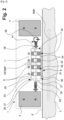
- An HF Electrical Coil (6) (or electrical circuit) is placed directly above a Perforated Matrix Laminated Magnetic Core (22). Its Winding Plane (7) (or circuit plane) is parallel to the local Inspected Surface (8) of the Inspected Material (3) facing the EMAT (1).
- the two Magnets (4) are positioned on either side of the Perforated Matrix Laminated Magnetic Core (22).
- the HF Electric Coil (6) is configured as an HF Electromagnetic Emitter (9) of an HF Emitted Electromagnetic Field (HFEMF). It is connected to the output of at least one Alternating Current Source (11), driving in the HF Electric Coil (6) an HF Alternating Current (AC) at ultrasonic frequency. This induces an HF Emitted Electromagnetic Field (HFEMF) in the direction of the Inspected Material (3).
- the HF Emitted Electromagnetic Field (HFEMF) produces Material Eddy Currents (14) on the surface of the Inspected Material (3).
- the EMAT (1) can also be used in Receive Mode (RM).
- the HF Electric Coil (6) is then configured as an HF Electromagnetic Receiver (18). It is traversed by a Secondary Ultrasonic Electric Current (19) at ultrasonic frequency.
- This HF current consists of Secondary Ultrasonic Electrical Signals (88) generated by an HF Emitted Electromagnetic Field (HFEMF) induced by Material Eddy Currents (14).
- HFEMF HF Emitted Electromagnetic Field
- These Material Eddy Currents (14) are produced on the Inspected Surface (8) of the Inspected Material (3) by Secondary Ultrasonic Waves (21), under the influence of an external ultrasonic source, in interaction with the Static Magnetic Field (SMF).
- SMF Static Magnetic Field
- a Perforated Matrix Laminated Magnetic Core (22) is positioned between the Inspected Surface (8) of the Inspected Material (3) and the HF Electric Coil (6), which directly faces it.
- the Perforated Matrix Laminated Magnetic Core (22) is configured to concentrate and direct the Emitted RF Electromagnetic Field (HFEMF) in the direction of and/or from the Inspected Material (3), depending on whether the mode of use of the EMAT ( 1) is transmitting or receiving. It is of the type comprising a Sandwich Matrix (23) consisting of a multitude of laminated Thin Sheets (24).
- the Perforated Matrix Laminated Magnetic Core (22) has multiple adjacent grooved Side Edge Faces (35) extending substantially perpendicular to the Stacking Plane (27) and parallel to the Matrix Axis (25).
- each Thin Sheet (24) laminated in the Matrix (23) has a spatial geometry and lateral dimensions similar to those of the neighboring Thin Sheets (24) in the Matrix (23). It has two main side Sheet Surfaces (32), parallel to the Stacking Plane (27).
- the sandwiched Matrix (23) comprises a First Multitude (28) of HF Active Pads (29) (four are shown in the figures), or groups of such pads.
- Each HF Active Pad (29) is isolated from the others. It incorporates internally a Magnetic Material (in particular ferromagnetic or ferrimagnetic) with high magnetic permeability. Magnetic Material has a certain Curie Temperature (TC). It externally incorporates an electrically conductive material. It can alternatively be covered externally with an electrically conductive layer on its Peripheral Edges (33).
- TC Curie Temperature
- a Grooved Cylindrical Aperture (39) passes through each Thin Sheet (24) of the Die (23), along an Aperture Axis (40) of the Die (23), substantially parallel to the Axis Of Matrix (25) and perpendicular to Core Axis (38). It leads to each of the two Matrix Faces (26).
- a multitude of Via Magnetic Holes (41), of similar section dimensions and with a closed perimeter, are perforated through and substantially in the center of each of the multiple Active HF Wafers (29) thus hollowed out of the Matrix (23), along an axis substantially parallel to the Inspected Surface (8).
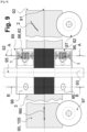
- the Induced Current Loops (43) are located within the Active Pad Skin (48) of the periphery of each HF Active Pads (29) of the Core Magnetic Perforated Matrix Laminate (22). As it appears [ Fig. 6 ] they are arranged according to a Loop Map (LM), defining the topology, the distribution, and the relative positions of all the Induced Current Loops (43).
- LM Loop Map
- Each Magnetic Via Hole (41) in each RF Active Pad (29) is located between the First Edge Face (36) facing the Inspected Surface (8), and the Second Edge Face (37) facing the HF Electric Coil (6).
- Each Magnetic Via Hole (41) of the Cylindrical Slotted Aperture (39) is internally free of any hard material. In particular, it is free of any electrical conductor passing through it.
- the Mapping Of Loops (LM) is topologically discrete and made up of a multitude of Induced Current Loops (43) in each Active Platelets HF (29), (or groups of such Active Platelets) distant from each other others.
- the Induced Current Loops (43) (or group of such Loops) are induced inside the Active Wafer Skin (48) on the Peripheral Edges (33) of the HF Active Wafers (29). They are each arranged along a plane of loops parallel to the Stacking Plan (27), and substantially perpendicular to the surface of the Inspected Material (3). They are substantially parallel, and separated from each other, between their respective Active HF Pads (29). They encircle the Magnetic Via Holes (41) of their Active HF Plate (29) and turn around. With reference to figure [ Fig.
- each Core Spacing Edge (49) of the Perforated Matrix Laminated Magnetic Core (22) and of its surface, located between two adjacent HF Active Wafers (29) (29) (or group), is free of any Induced Current Loops (43), and more generally free of any induced electric current.
- the HF Emitted Electromagnetic Field (HFEMF), and the Perforated Matrix Laminated Magnetic Core (22) are configured such that, when the EMAT (1) is in operation, the HF Core Magnetic Field (HFIMF ) has a component significant HF Core Transverse Magnetic Field (MFFTF), which is perpendicular to the Stacking Plane (27), perpendicular to each HF Active Wafer (29), and substantially parallel to the surface of the Inspected Material (3).
- MFFTF HF Core Transverse Magnetic Field
- the HF Magnetic Flux (HFHF) within the Perforated Matrix Laminated Magnetic Core (22) has a large component perpendicular to the Core Axis (38) and parallel to the surface of the Inspected Material (3).
- Closed Induced Current Loops (43) are generated by the RF Core Transverse Magnetic Field (MFFTF) on the Peripheral Edge (33) of each RF Active Pad (29).
- the Induced Current Loops (43) parallel to the Active HF Plates (29) participate by pooling in the overall reduction of the high frequency magnetic reluctance of the EMAT (1).
- the Inner Perimeter (45) of each Magnetic Via Hole (41) in each HF Active Wafer (29) of the Matrix (23) creates a Thermo-Conductive and Convective Surface (46) at the center of its Active Wafer HF (29). This produces an internal Thermal Cooling effect to dissipate a fraction of the local electrical and heat energy generated by the Induced Current Loop (43) specific to each HF Active Pad (29). This participates by pooling in improving the efficiency of the EMAT (1).
- each HF Active Pad (29) hollowed out of the Matrix (23) (or group of such Active Wafers) is separated from its neighbors, at adjacent Core Spacer Wafers (49), by at least one sheet of a Second Multitude (54) of Passive Wafers (53 ) made of an electrically insulating material.
- Each Passive Pad (53) is perforated by a Via Spacer Hole (57).
- Each Passive Pad (53) is positioned and configured such that the Magnetic Via Holes (41) in the First Multitude (28) of HF Active Pads (29) of the Matrix (23), as well as the Via Spacer Holes (57 ) of the Second Multitude (54) of Passive Pads (53) of the Matrix (23), are aligned parallel to the Matrix Axis (25). They form by their alignment and their combination the Grooved Cylindrical Opening (39).
- Each Spacer Via Hole (57) in each Passive Pad (53) is located between the First Border Face (36) facing the Inspected Material (3), and the Second Border Face (37) facing the HF Electric Coil (6).
- Each Via Spacer Hole (57) of the Grooved Cylindrical Aperture (39), is internally free of any hard material. In particular, it is free of any electrical conductor passing through it.
- each Hole Via Spacer (57) in each Passive Wafer (53) of the Matrix (23) creates a free internal Thermo-Conductive and Convective Surface (46) at the center of the Passive Wafer (53) .
- the Peripheral Edges (33) of their edges be free of any conductive material covering their surfaces.
- the grooved Edge Surface (34) of the Perforated Matrix Laminated Magnetic Core (22) is not continuously covered and/or made up of an electrically conductive layer, but on the contrary it consists of alternating edges to edges on the one hand of conductive rings around the HF Active Pads (29) and on the other hand of insulating rings around the Passive Pads (53).
- the Perforated Matrix Laminated Magnetic Core (22) of the EMAT (1) comprises Cooling Means (58). They generate a Calorific Flux (59) of a Calorific Fluid (60) at a Cooling Temperature (TF). This Heat Flux (59) is forced to pass through the Grooved Cylindrical Aperture (39) of the Matrix (23).
- the Calorific Flux (59) for cooling is configured to pass successively through one of the Magnetic Via Holes (41) of the First Multitude (28) and, alternatively, at least one of the Via Spacer Holes (57) of the Second Multitude ( 54).
- At least one (and preferably a multitude of) Thin Sheet(s) (24) of the Perforated Matrix Laminated Magnetic Core (22) is - either pierced by a Cushion Hole (63), - or provided with a Cushion (64). These openings pass through the Annular Wall (65) formed between their Via Holes (41, 57), and the portion of their First Edge Face (36) facing the Inspected Material (3), this in a direction parallel to the Plane Stacking (27). This creates a Cushion Recess (66) between the Via Holes (41, 57) of the Thin Sheet (24) and the First Border Face (36) facing the Inspected Material (3).
- the Cooling Means (58) are configured to extract a Cushion Fluid Flow (67) from the Heat Flux (59) traversing the Via Holes (41, 57). They pressurize this extracted Cushion Fluid Flow (67) through the Cushion Recess (66). This creates a lifting Air Cushion (70) between the Perforated Matrix Laminated Magnetic Core (22) and the Inspected Material (3), at the Cushion Recess (66) facing the Inspected Material (3). This raises the Perforated Matrix Laminated Magnetic Core (22) above the Inspected Material (3) by a Cushion Gap (68). This arrangement is reliable. It provides automatic mechanical adjustment of the Cushion Gap (68).
- the two outer side Border Faces (35) of the two outer Thin Sheets located on the Matrix Faces (26) are either made of, or covered (as shown) by a Conductive Cover Layer (69), of an electrically conductive material .
- This EMAT configuration (1) has the following characteristics. A Via Hole of similar cross-sectional dimensions as the Magnetic Via Holes (41) is punched through each of the two Conductive Cover Layers (69).
- the multiple Thin Sheets (24) and the two Conductive Cover Layers (69) of the Matrix (23) are positioned relative to each other such that their multiple via holes are aligned to form the Cylindrical Grooved Aperture in continuity (39).
- each HF Active Wafer (29) is topologically configured as a rectangular Active Ring (71), thermodynamically cooled by the heating of the Induced Current Loop (43) generated around it.
- the HF Electric Coil (6) and the First Multitude (28) of HF Active Pads (29) in the Matrix (23) are configured such that: the orientation, pitch, size and shape of each of the Edges Circuit Face (72) of each HF Active Wafer (29), located in the Second Edge Face (37) of the Die (23), and facing the HF Electric Coil (6); are consistent and correlated with the geometrical parameters, including orientation, pitch, size and shape, of the Conductor Fractions (75) of the HF Electric Coil (6) successively facing each of these Face Circuit Edges ( 72).
- the HF Electric Coil (6) has at least a part of Linear Conductor (73). This is positioned near and directly above an Edge Face Circuit (72). It is tangent, along a parallel axis, to this part adjacent to the perimeter of an Active HF Wafer (29) located in the Second Edge Face (37) of the Matrix (23) facing the HF Electric Coil (6).
- Linear Conductor fraction (73) and the Perforated Matrix Laminated Magnetic Core (22) are configured in such a way that, when the EMAT (1) is in operation, a Current Loop Induced (43) is induced in the Active Platelet Skin (48) around the HF Active Platelet (29). She surrounds her Magnetic Via Hole (41).
- EMAT (1) is in Transmit Mode (EM), as depicted in the figure Fig.3 , then the HF Alternating Current (AC) flowing through the Linear Conductor fraction (73) produces a looping ortho radial magnetic flux, generating a Conductor HF Magnetic Flux Loop (76), creating a Core HF Transverse Magnetic Field (MFFTHF ), which is substantially perpendicular to the HF Active Pad (29) facing it. This causes an Induced Current Loop (43) on the surface of the Active Ring (71) of the Active HF Wafer (29).
- AC Alternating Current
- MFFTHF Core HF Transverse Magnetic Field
- This Induced Current Loop (43) emits a multitude of HF magnetic flux loops which produce Eddy Currents Of The Material (14) topologically ordered and all oriented along an axis substantially parallel to the plane of the Active HF Wafer (29) which faces nearby directly above.
- a circular coil supplied with a current produces a bundle of magnetic field lines, in the form of a multitude of loops of magnetic flux parallel to the axis of the circular coil, and passing through its center.
- the Induced Current Loop Loop (43) longitudinally surrounding this HF Active Pad (29) then emits a multitude of HF magnetic flux loops which encircle the fraction of Linear Conductor (73) which is tangent to it along a parallel axis part of the perimeter of this Active HF Pad (29).
- This inductively generates a Secondary Ultrasonic Electrical Signal (88) which creates an HF Alternating Current (AC) in the Linear Conductor portion (73).
- the HF Electric Coil (6) is a Meander Circuit (74). It presents a multitude of (at least two) Linear Conductor fractions (73) (four are shown in figure [ Fig. 6 ]). They are parallel and close to each other. The multitude of these Linear Conductor fractions (73) of the Meander Circuit (74) are successively positioned near, and directly above an Edge Face Circuit (72) of one of the Active HF Pads (29), located in the Second Edge Face (37) of the Matrix (23) facing the HF Electric Coil (6).
- the Linear Conductor (73) fractions of the Meander Circuit (74) and the Perforated Matrix Laminated Magnetic Core (22) are configured such that when the EMAT (1) is Emission Mode (EM), two HF Active Pads (29) neighbors, surmounted by two neighboring Linear Conductor fractions (73), are traversed in their Active Pad Skin (48) by two Induced Current Loops (43) neighbours. They are each composed of an HF alternating electric current rotating in an opposite Direction Of Rotation (78), around the Aperture Axis (40) passing through their Magnetic Via Holes (41), one being in the clockwise, while the other is counterclockwise.
- the Opening Depth (Od) of the Grooved Cylindrical Opening (39) of the Perforated Matrix Laminated Magnetic Core (22), along its Opening Axis (40), is substantially equal and consistent with a First Transverse Dimension (FTd) of the HF Electric Coil (6) of the EMAT (1).
- the grooved Second Border Face (37) of its Perforated Matrix Laminated Magnetic Core (22), facing the HF Electric Coil (6) has a transverse dimension, in a direction perpendicular to the Aperture Axis. (40) of the Matrix (23), which is substantially equal and consistent with a Second Transverse Dimension (STd) of the HF Electric Coil (6) of the EMAT (1).
- the Sheet Geometric Dimensions (79) of the Perforated Thin Sheets (24) of its Matrix (23) and the combined geometric dimensions of its Perforated Matrix Laminated Magnetic Core (22) are selected to be decorrelated from the wavelengths of the main harmonics of the HF Emitted Electromagnetic Field (HFEMF). Understandably, this prevents mechanical resonance of its Perforated Matrix Laminated Magnetic Core (22) at the ultrasonic operating frequency of the EMAT (1).
- HFEMF HF Emitted Electromagnetic Field
- the Sheet Geometric Dimensions (79) of the perforated Thin Sheets (24) of its Perforated Matrix Laminated Magnetic Core (22) are chosen such that, at the ultrasonic frequency of operation of the EMAT (1), they are either much smaller than the wavelengths of the ultrasonic waves generated in these Thin Sheets (24), or, substantially equal to an odd number of quarters of the wavelengths ultrasonic waves generated in these Thin Sheets (24).
- the grooved First Border Face (36) of the Perforated Matrix Laminated Magnetic Core (22), facing the Inspected Material (3) and parallel to the Grooved Cylindrical Aperture (39) is either covered or covered with a Insulating Layer (81) (as illustrated), made of an electrically insulating material.
- a Insulating Layer (81) (as illustrated), made of an electrically insulating material.
- One of the faces of the Insulating Layer (81) is arranged opposite the Grooved Cylindrical Opening (39), and covers the edge belonging to the First Edge Face (36), of the perimeter of each of the Active HF Pads (29) .
- This EMAT (1) enhances the transmission of HF Emitted Electromagnetic Field (HFEMF) energy. It maximizes the HF magnetic coupling and minimizes the HF Emitted Electromagnetic Field (HFEMF) flux leakage, between the HF Electric Coil (6) and the Material Eddy Currents (14) generated at the surface of the Inspected Material (3). It ensures surface topological homogeneity of the efficiency of this high frequency electromagnetic coupling between the HF Electric Coil (6) and the inspected Material Eddy Currents (14) facing the transducer. It operates at high temperatures of the Inspected Material (3) above 1000°C.
- HFEMF HF Emitted Electromagnetic Field
- the LEMAT comprises the combination of: i) an Acoustic Electromagnetic Transducer (EMAT) (1) according to the invention as described above, and ii) a Laser Source (84).
- the EMAT (1) is configured in Receive Mode (RM), to receive a Secondary Ultrasonic Electrical Signal (88) from the Inspected Material (3).
- the HF Electric Coil (6) is configured as an HF Electromagnetic Receiver (18). As it appears in figure [ Fig.
- this Secondary Ultrasonic Electrical Signal (88) is electrically induced by an HF Emitted Electromagnetic Field (HFEMF) emitted by the Inspected Material (3), generated by Material Eddy Currents (14) produced in the Inspected Material (3) by Secondary Ultrasonic Waves (21).
- HFEMF HF Emitted Electromagnetic Field
- These Eddy Currents Of The Material (14) are representative of the surface and/or internal Discontinuities (2) of the Inspected Material (3).
- the Laminated Perforated Matrix Magnetic Core (22) is located between the HF Electric Coil (6) of the EMAT (1) and the local surface of the Inspected Material (3). It directly faces the HF Electric Coil (6).
- the Laser Source (84) is configured to fire a high energy Laser Beam (85) at a Shooting Point (86) on the surface of the Inspected Material (3).
- the Laser Beam (85) generates Primary Ultrasonic Waves (17) propagating on the surface and/or inside the Inspected Material (3). This causes the generation of Secondary Ultrasonic Waves (21) resulting from the echoes of the interactions of the Primary Ultrasonic Waves (17) with the discontinuities (2) on and/or inside the Inspected Material (3).
- the Laser-EMAT (LEMAT) Probe (82) has the following technical characteristics.
- a multitude of distant Induced Current Loops (43) are induced by the HF Emitted Electromagnetic Field (HFEMF) emitted by eddy currents (14) in the Inspected Material (3) under the influence of the Laser Source (84), inside the Active Wafer Skin (48) on the Peripheral Edges (33) of each HF Active Wafer (29) of the Perforated Matrix Laminated Magnetic Core (22).
- HFEMF HF Emitted Electromagnetic Field
- eddy currents (14) in the Inspected Material (3) under the influence of the Laser Source (84), inside the Active Wafer Skin (48) on the Peripheral Edges (33) of each HF Active Wafer (29) of the Perforated Matrix Laminated Magnetic Core (22).
- these Induced Current Loops (43) of each Active HF Plate (29) (or group) are distant from each other.
- Eddy Current Loops surround and rotate around the Active Ring (71) magnetically, surrounding the Magnetic Via Holes (41) of the HF Active Pads (29). They are located between the First Border Face (36) facing the Inspected Material (3) and the Second Border Face (37) facing the HF Electric Coil (6). They are positioned substantially perpendicular to these two Sides Of Borders (36, 37).
- the LEMAT (82) of the invention offers a technical solution to the technical problem (b) above. It optimizes the detection resolution of Surface, Sub-Surface and Deep Sub-Surface Discontinuities (2) in a thick metallic structure. It operates at high temperatures of the Inspected Material (3) above 1000°C.
- a Multi Laser-EMAT (MLEMAT) 3D Scanner (89) is shown, for the detection of surface and/or internal Discontinuities (2) inside a moving cylindrical Conductive Structure (90).
- the MLEMAT (89) comprises: a) a Conductive Structure (90) to be scanned in 3D; b) a Chassis Frame (93); c) a Multitude Of Probes (96) made up of at least two Laser-EMAT (LEMAT) Probes (82) according to the invention, and d) Moving Means (97).
- the Conductive Structure (90) to be 3D scanned is made of an electrically conductive Inspected Material (3).
- the Chassis Frame (93) is configured to surround the Conductive Structure (90) at a Frame Distance (Fd). Its Frame Plane (95) is substantially perpendicular to the Structural Axis (91) of the Conductive Structure (90).
- the Movement Means (97) are configured to linearly move the cylindrical Conductive Structure (90) relative to the Chassis Frame (93), along a Direction Of Movement (Md), substantially combined with the Structure Axis (91 ).
- This Multi Laser-EMAT (MLEMAT) 3D Scanner (89) has the following feature which appears with reference to figure [ Fig. 10 ].
- the Aperture Loop (99) consisting of the virtual line joining the centers of each successive Grooved Cylindrical Aperture (39) of the Laminated Perforated Matrix Magnetic Core (22) of each adjacent EMAT (1) of the Laser-EMAT Probes (LEMAT) (82) of the MLEMAT (89), encircles the Conductive Structure (90).
- the Multitude Of Probes (96) made of Laser-EMATs (82) are fixed on the Chassis Frame (93), positioned and configured in a position such that the juxtaposition of the multitude of First Edge Faces (36) adjacent to the Perforated Matrix Laminated Magnetic Cores (22) of each of the adjacent Laser-EMAT (LEMAT) Probes (82), facing the Inspected Material (3), are substantially contiguous to each other, constitutes an Inspection Ring (100 ) substantially continuous grooved.
- This grooved Inspection Ring (100) surrounds and covers the perimeter of the Conductive Structure (90), in a Structural Section (92) of the Conductive Structure (90) adjacent to the Frame Plane (95).
- the Laser Source (84) of each LEMAT (82) consists of an Optical Fiber (101), fixed on the Chassis Frame (95), having a Firing End (102) facing the Conductive Structure (90 ).
- Each Optical Fiber (101) is connected to a Laser Generator (103).
- This configuration of the Multi Laser-EMAT (MLEMAT) 3D Scanner (89) has the following characteristic.
- the Laser Firing Loop (104) constituted by the virtual line joining the Firing Ends (102) of each Laser-EMAT Probe (LEMAT) (82) adjacent to the MLEMAT (89), encircles the Conductive Structure (90) and is substantially parallel to the Loop of Openings (99).
- the Multi Laser-EMAT (MLEMAT) 3D scanner (89) of the invention is operated for the detection of surface and/or internal Discontinuities (2) of a Metallurgical Slab (105 ).
- the Conductive Structure (90) is then a mobile cylindrical Metallurgical Slab (105) with respect to the MLEMAT (89).
- the Aperture Loop (99) consisting of the virtual line joining the centers of each successive Grooved Cylindrical Aperture (39) of the Laminated Perforated Matrix Magnetic Core (22) of each adjacent EMAT (1) of the Laser-EMAT Probes (LEMAT) (82) of the MLEMAT (89), encircles the mobile cylindrical Metallurgical Slab (105).
- Multi Laser-EMAT (MLEMAT) 3D Scanner (89) of the invention is used for the detection of surface and/or internal Discontinuities (2) of a Steel Slab ( 105) mobile cylindrical; continuous casting in a steel mill at a Casting Temperature (TS) greater than 1000°C. consist of a Magnetic Material, for example of the ferromagnetic or ferrimagnetic type, having a Curie Temperature (TC) lower than the Casting Temperature (TS).
- TS Casting Temperature
- TC Curie Temperature
- each Grooved Cylindrical Opening (39) of each Perforated Matrix Laminated Magnetic Core (22) of each EMAT (1) of each LEMAT (82) adjacent to the MLEMAT (89), is connected to Cooling Means (58) generating a Calorific Flux (59) of a Calorific Cooling Fluid (60).
- the Calorific Fluid (60) is pushed under pressure into each hole via (41, 57) the Grooved Cylindrical Aperture (39) of each Perforated Matrix Laminated Magnetic Core (22) of each adjacent EMAT (1) of the MLEMAT (89), at a Cooling Temperature (TF) significantly lower (by at least 50°c) than the Curie Temperature (TC) of the Magnetic Material of the hollow Active Wafers HF(29).
- TF Cooling Temperature significantly lower (by at least 50°c) than the Curie Temperature (TC) of the Magnetic Material of the hollow Active Wafers HF(29).
- This MLEMAT performs continuous 3D scanning per line of large and thick moving Conductive Structures (90), such as metallurgical slabs (105), from a single location, generating a high-resolution observed 3D mapping of this structure, including providing the location of deep surface and subsurface Discontinuities (2). It operates at high temperatures of the Inspected Material (3) above 1000°C.
- the Multi Laser-EMAT (MLEMAT) 3D Scanner (89) configured for the automatic adjustment of the dynamic parameters of the Soft Dynamic Reduction (DSR) of a Steel Slab (105) continuously cast in a steel mill at a Casting Temperature (TS) greater than 1000°C.
- the Steel Slab (105) is continuously pushed through a Soft Dynamic Reduction Device (DSRD), to suppress formation a macro-segregation zone and porosity zones inside the Steel Slab (105); this by dynamically compensating for the solidification shrinkage of the steel and by interrupting the suction flow of the residual molten metal in the Central Soft Zone (106) of the Steel Slab (105).
- DSRD Soft Dynamic Reduction Device
- This MLMAT (89) is coupled to a Soft Dynamic Reduction Device (DSRD) which includes: i) a Dynamic 3D Mapping System (3DMS), generating a Dynamic 3D Mapping (3DM) of the casting of the Slab Steel (105); ii) a computer-based DSR Optimization System (DSRM), generating Dynamic DSR Optimization Parameters (PCSD), based on 3D Dynamic Mapping (3DM) and casting parameters; and iii) a Digital DSR Activator (ASR), dynamically adjusting the DSR Action Parameters (PASD) of the Soft Dynamic Reduction Device (DSRD), based on the PCSDs generated by the DSRM.
- a Dynamic 3D Mapping System 3DMS
- DSRM Dynamic DSR Optimization System
- PCSD Dynamic DSR Optimization Parameters
- ASR Digital DSR Activator
- PASD DSR Action Parameters
- This Multi Laser-EMAT (MLEMAT) (89) 3D Scanner has the following features.
- the HF Electric Coils (6a, 6b, 6) of each EMAT (1a, 1b, 1) of each Laser-EMAT (82a, 82b, 82) of the MLEMAT (89) are each connected to the 3D Dynamic Mapping System (3DMS) . They transmit to it a Secondary Ultrasonic Electric Signal (88a, 88b, 88) induced in each HF Electric Coil (6a, 6b, 6) by the Eddy Currents Of The Material (14) on the Frontal Zone (110) of the Inspected Material (3 ) of the Steel Slab (105) locally facing each EMAT (1a, 1b, 1).
- 3DMS 3D Dynamic Mapping System
- the DSR Optimization System is equipped with Analogue and Digital Processing Means (MDAN).
- the MDANs are configured to receive the multitude of Secondary Ultrasonic Electrical Signals (88a, 88b, 88) included in the Secondary Ultrasonic Electrical Streams (19a, 19b, 19) flowing through each HF Electrical Coil (6) in each Laser-EMAT (82a, 82b, 82) of MLEMAT (89).
- the MDANs are also configured to identify changes and disturbances in each Secondary Ultrasonic Electrical Signal (88a, 88b, 88) of each Laser-EMAT (82a, 82b, 82), caused by Discontinuities (2) in the Local Active Fraction (44a, 44b, 44) of the Inspected Material (3) facing each Laser-EMAT (82a, 82b, 82), and deduce therefrom the Frontal Topology of Defects (DTa, DTb, DT) in this Local Active Fraction ( 44a, 44b, 44).
- the MDANs are also configured to digitally combine the Frontal Defect Topologies (DTa, DTb, DT), and digitally generate a three-dimensional Dynamic 3D Mapping (3DM) physically observed by the MLEMAT from within the casting of the Steel Slab (105), in the Front Zone (110) facing the Inspection Ring (100) in the Structure Section (92) of the Frame Plane (95), based on the combination and digital analysis of the combined signals multiple Secondary Ultrasonic Electrical Signals (88a, 88b, 88).
- 3DM Three-dimensional Dynamic 3D Mapping
- the Cooling Means (58) generate a Heat Flux (59) of a Calorific Fluid (60), pushed under pressure inside each hole via (41, 57) of the Grooved Cylindrical Opening (39) each Perforated Matrix Laminated Magnetic Core (22) of each adjacent EMAT (1) of the MLEMAT (89); this at a Cooling Temperature (TF) significantly lower (by at least 50°C) than the Curie Temperature (TC) of the Magnetic Material of the hollowed HF(29) Active Wafers.
- TF Cooling Temperature
- TC Curie Temperature
- the DSR Action Parameters (PASD) of the Soft Dynamic Reduction Device (DSRD) can be dynamically adjusted in an optimal way, on the basis of a 3D Dynamic Mapping (3DM) of the casting of the Steel Slab (105) physically observed by the MLEMAT (89), at a Casting Temperature (TS) greater than 1000°C.
- 3DM 3D Dynamic Mapping
- the MLMAT (89) is coupled to a Secondary Dynamic Cooling Device (DSCD) which further comprises a Computerized DSC Optimization Model (DSCM), generating Secondary Dynamic Cooling (DSC) Dynamic DSC Optimization (PCSC) Parameters based on the physically observed Dynamic 3D Mapping (3DM) of the Steel Slab casting ( 105), in the Structure Section (92) of the Frame Plane (95), by combining and digitally analyzing the combined signals of the multiple Secondary Ultrasonic Electrical Signals (88a, 88b, 88) in each Laser-EMAT (82a, 82b, 82) of the MLEMAT (89), and on the casting parameters.
- DSCD Secondary Dynamic Cooling Device
- DSCM Computerized DSC Optimization Model
- PCSC Dynamic DSC Optimization
- ASC Digital DSC Activator
- PASC DSC Action Parameters
- DSC Dynamic Secondary Cooling
- the MLEMAT (89) for the automatic adjustment of the DSR and/or DSC of the invention offers a technical solution to the technical problem (d) above. It provides automatic adjustment of DSR Action Parameters (PASD) of Dynamic Soft Reduction (DSR) and/or DSC Action Parameters (PASC) of Secondary Dynamic Cooling (DSC), of a continuous casting of Steel Slabs (105) in a steel mill, based on the condition observed from inside the cast Steel Slab (105). It provides a continuous 3D Dynamic Mapping (3DM) observed from within the cast Steel Slab (105).
- PASD DSR Action Parameters
- DSR Dynamic Soft Reduction
- PASC DSC
- DSC Secondary Dynamic Cooling
- the invention has industrial applications in the metallurgical industry, and in particular in the steel industry, for the quality test and the automatic adjustment of the DSR and/or the DSC of steel slabs. hot to more than 1000°C in continuous casting lines in steelworks, and for quality control of semi-finished products in the steel industry.
- the invention also has industrial applications in the railway industry, for the high-speed control of railway rails, and the control of wheelsets.
- the invention also has industrial applications in the oil and gas, chemical and nuclear industries, for on-line testing of pipes and pipelines, drilling rigs and equipment in hazardous and/or hazardous environments. at high temperature.
Landscapes
- Physics & Mathematics (AREA)
- General Physics & Mathematics (AREA)
- Pathology (AREA)
- Life Sciences & Earth Sciences (AREA)
- Chemical & Material Sciences (AREA)
- Analytical Chemistry (AREA)
- Biochemistry (AREA)
- Health & Medical Sciences (AREA)
- Immunology (AREA)
- General Health & Medical Sciences (AREA)
- Electromagnetism (AREA)
- Optics & Photonics (AREA)
- Engineering & Computer Science (AREA)
- Mechanical Engineering (AREA)
- Acoustics & Sound (AREA)
- Investigating Or Analyzing Materials By The Use Of Ultrasonic Waves (AREA)
Priority Applications (1)
| Application Number | Priority Date | Filing Date | Title |
|---|---|---|---|
| EP21020516.7A EP4166246B1 (de) | 2021-10-14 | 2021-10-14 | Emat-system zur erkennung von oberflächen- und inneren diskontinuitäten in leitfähigen strukturen bei hohen temperaturen |
Applications Claiming Priority (1)
| Application Number | Priority Date | Filing Date | Title |
|---|---|---|---|
| EP21020516.7A EP4166246B1 (de) | 2021-10-14 | 2021-10-14 | Emat-system zur erkennung von oberflächen- und inneren diskontinuitäten in leitfähigen strukturen bei hohen temperaturen |
Publications (2)
| Publication Number | Publication Date |
|---|---|
| EP4166246A1 true EP4166246A1 (de) | 2023-04-19 |
| EP4166246B1 EP4166246B1 (de) | 2025-04-02 |
Family
ID=78211785
Family Applications (1)
| Application Number | Title | Priority Date | Filing Date |
|---|---|---|---|
| EP21020516.7A Active EP4166246B1 (de) | 2021-10-14 | 2021-10-14 | Emat-system zur erkennung von oberflächen- und inneren diskontinuitäten in leitfähigen strukturen bei hohen temperaturen |
Country Status (1)
| Country | Link |
|---|---|
| EP (1) | EP4166246B1 (de) |
Cited By (1)
| Publication number | Priority date | Publication date | Assignee | Title |
|---|---|---|---|---|
| CN116930325A (zh) * | 2023-07-25 | 2023-10-24 | 哈尔滨工业大学 | 用于金属管道缺陷成像的电磁超声复合式换能器 |
Citations (3)
| Publication number | Priority date | Publication date | Assignee | Title |
|---|---|---|---|---|
| JPS6175259A (ja) * | 1984-09-19 | 1986-04-17 | Toshiba Corp | 電磁超音波トランスジユ−サ |
| JPH10282071A (ja) * | 1997-04-10 | 1998-10-23 | Toshiba Corp | 電磁超音波トランスジューサ |
| US7546770B2 (en) | 2006-01-05 | 2009-06-16 | General Electric Company | Electromagnetic acoustic transducer |
-
2021
- 2021-10-14 EP EP21020516.7A patent/EP4166246B1/de active Active
Patent Citations (3)
| Publication number | Priority date | Publication date | Assignee | Title |
|---|---|---|---|---|
| JPS6175259A (ja) * | 1984-09-19 | 1986-04-17 | Toshiba Corp | 電磁超音波トランスジユ−サ |
| JPH10282071A (ja) * | 1997-04-10 | 1998-10-23 | Toshiba Corp | 電磁超音波トランスジューサ |
| US7546770B2 (en) | 2006-01-05 | 2009-06-16 | General Electric Company | Electromagnetic acoustic transducer |
Cited By (2)
| Publication number | Priority date | Publication date | Assignee | Title |
|---|---|---|---|---|
| CN116930325A (zh) * | 2023-07-25 | 2023-10-24 | 哈尔滨工业大学 | 用于金属管道缺陷成像的电磁超声复合式换能器 |
| CN116930325B (zh) * | 2023-07-25 | 2024-05-24 | 哈尔滨工业大学 | 用于金属管道缺陷成像的电磁超声复合式换能器 |
Also Published As
| Publication number | Publication date |
|---|---|
| EP4166246B1 (de) | 2025-04-02 |
Similar Documents
| Publication | Publication Date | Title |
|---|---|---|
| Pieris et al. | Laser Induced Phased Arrays (LIPA) to detect nested features in additively manufactured components | |
| WO2022054036A2 (fr) | Système emat pour la détection de discontinuités de surface et internes dans des structures conductrices à haute température | |
| FR2548351A1 (fr) | Procede et appareillage de mesure sans contact d'une coquille solidifiee d'une piece metallique coulee | |
| EP0493146A1 (de) | Vorrichtung zur zerstörungsfreien Prüfung von länglichen Elementen mit annähernd konstantem Querschnitt | |
| EP4166246B1 (de) | Emat-system zur erkennung von oberflächen- und inneren diskontinuitäten in leitfähigen strukturen bei hohen temperaturen | |
| CA3039923A1 (fr) | Procede d'inspection automatique d'un cordon de soudure depose dans un chanfrein forme entre deux pieces metalliques a assembler | |
| CN106841306A (zh) | 一种基于旋转磁场的感应涡流热成像检测装置 | |
| Wu et al. | Surface crack detection for carbon fiber reinforced plastic materials using pulsed eddy current based on rectangular differential probe | |
| RU2653663C1 (ru) | Устройство электромагнитно-акустического контроля рельсов | |
| WO2007141428A1 (fr) | Dispositif et procede de controle non destructif permettant de determiner la presence de materiau magnetique dans des materiaux non magnetique ou presentant une anisotropie magnetique : cristalline, de structure metallurgique, de forme ou de tension | |
| RU2847447C1 (ru) | Система емат для выявления поверхностных и внутренних несплошностей в проводящих структурах при высокой температуре | |
| CN208366914U (zh) | 一种油气输送用钢板电磁超声自动检测系统 | |
| Li et al. | Analysis of source influence on guided wave excitation in cylindrical structures using spatial fourier transform method | |
| Passini et al. | Ultrasonic inspection of AA6013 laser welded joints | |
| FR3013844A1 (fr) | Dispositif pour le controle non destructif d'un objet a controler | |
| CA2858922A1 (fr) | Procede de fabrication d'une tete de controle d'un capteur de controle non destructif a courants de foucault | |
| JP2020197488A (ja) | 校正用サンプルおよび校正用サンプル作成方法 | |
| WO2022172260A1 (fr) | Dispositif agile undt à double matrice emats/impulsions-laser pour le scanning d'objets métallurgiques | |
| Dimakos et al. | Evaluation of signal disturbance and recovery in phased array ultrasonic inspection during welding | |
| Takishita et al. | Development of point-focusing EMATs with large iIncident angles beyond conventional design limitation | |
| Nicolson | Considerations for an in-process ultrasonic phased array inspection method for narrow gap welds | |
| FR3021115A1 (fr) | Procede de fabrication d'une tete de controle d'un capteur de controle non destructif a courants de foucault | |
| Kim et al. | Flaw detection of railroad wheel tread using EMAT | |
| Wang et al. | Surface Crack Detection by Laser Excitation-unidirectional EMAT Receiving | |
| Le Baron et al. | Enhanced resolution transducers for thick pieces ultrasonic inspection: The Fermat transducer concept |
Legal Events
| Date | Code | Title | Description |
|---|---|---|---|
| STAA | Information on the status of an ep patent application or granted ep patent |
Free format text: STATUS: UNKNOWN |
|
| PUAI | Public reference made under article 153(3) epc to a published international application that has entered the european phase |
Free format text: ORIGINAL CODE: 0009012 |
|
| STAA | Information on the status of an ep patent application or granted ep patent |
Free format text: STATUS: THE APPLICATION HAS BEEN PUBLISHED |
|
| AK | Designated contracting states |
Kind code of ref document: A1 Designated state(s): AL AT BE BG CH CY CZ DE DK EE ES FI FR GB GR HR HU IE IS IT LI LT LU LV MC MK MT NL NO PL PT RO RS SE SI SK SM TR |
|
| STAA | Information on the status of an ep patent application or granted ep patent |
Free format text: STATUS: REQUEST FOR EXAMINATION WAS MADE |
|
| 17P | Request for examination filed |
Effective date: 20240109 |
|
| RBV | Designated contracting states (corrected) |
Designated state(s): AL AT BE BG CH CY CZ DE DK EE ES FI FR GB GR HR HU IE IS IT LI LT LU LV MC MK MT NL NO PL PT RO RS SE SI SK SM TR |
|
| GRAP | Despatch of communication of intention to grant a patent |
Free format text: ORIGINAL CODE: EPIDOSNIGR1 |
|
| STAA | Information on the status of an ep patent application or granted ep patent |
Free format text: STATUS: GRANT OF PATENT IS INTENDED |
|
| INTG | Intention to grant announced |
Effective date: 20240611 |
|
| GRAS | Grant fee paid |
Free format text: ORIGINAL CODE: EPIDOSNIGR3 |
|
| STAA | Information on the status of an ep patent application or granted ep patent |
Free format text: STATUS: THE APPLICATION IS DEEMED TO BE WITHDRAWN |
|
| STAA | Information on the status of an ep patent application or granted ep patent |
Free format text: STATUS: GRANT OF PATENT IS INTENDED |
|
| GRAA | (expected) grant |
Free format text: ORIGINAL CODE: 0009210 |
|
| STAA | Information on the status of an ep patent application or granted ep patent |
Free format text: STATUS: THE PATENT HAS BEEN GRANTED |
|
| 18D | Application deemed to be withdrawn |
Effective date: 20241012 |
|
| D18D | Application deemed to be withdrawn (deleted) | ||
| AK | Designated contracting states |
Kind code of ref document: B1 Designated state(s): AL AT BE BG CH CY CZ DE DK EE ES FI FR GB GR HR HU IE IS IT LI LT LU LV MC MK MT NL NO PL PT RO RS SE SI SK SM TR |
|
| REG | Reference to a national code |
Ref country code: CH Ref legal event code: EP |
|
| REG | Reference to a national code |
Ref country code: IE Ref legal event code: FG4D Free format text: LANGUAGE OF EP DOCUMENT: FRENCH |
|
| REG | Reference to a national code |
Ref country code: DE Ref legal event code: R096 Ref document number: 602021028349 Country of ref document: DE |
|
| REG | Reference to a national code |
Ref country code: NL Ref legal event code: MP Effective date: 20250402 |
|
| PG25 | Lapsed in a contracting state [announced via postgrant information from national office to epo] |
Ref country code: NL Free format text: LAPSE BECAUSE OF FAILURE TO SUBMIT A TRANSLATION OF THE DESCRIPTION OR TO PAY THE FEE WITHIN THE PRESCRIBED TIME-LIMIT Effective date: 20250402 |
|
| REG | Reference to a national code |
Ref country code: AT Ref legal event code: MK05 Ref document number: 1780790 Country of ref document: AT Kind code of ref document: T Effective date: 20250402 |
|
| PG25 | Lapsed in a contracting state [announced via postgrant information from national office to epo] |
Ref country code: ES Free format text: LAPSE BECAUSE OF FAILURE TO SUBMIT A TRANSLATION OF THE DESCRIPTION OR TO PAY THE FEE WITHIN THE PRESCRIBED TIME-LIMIT Effective date: 20250402 Ref country code: FI Free format text: LAPSE BECAUSE OF FAILURE TO SUBMIT A TRANSLATION OF THE DESCRIPTION OR TO PAY THE FEE WITHIN THE PRESCRIBED TIME-LIMIT Effective date: 20250402 Ref country code: PT Free format text: LAPSE BECAUSE OF FAILURE TO SUBMIT A TRANSLATION OF THE DESCRIPTION OR TO PAY THE FEE WITHIN THE PRESCRIBED TIME-LIMIT Effective date: 20250804 |
|
| REG | Reference to a national code |
Ref country code: LT Ref legal event code: MG9D |
|
| PG25 | Lapsed in a contracting state [announced via postgrant information from national office to epo] |
Ref country code: NO Free format text: LAPSE BECAUSE OF FAILURE TO SUBMIT A TRANSLATION OF THE DESCRIPTION OR TO PAY THE FEE WITHIN THE PRESCRIBED TIME-LIMIT Effective date: 20250702 Ref country code: GR Free format text: LAPSE BECAUSE OF FAILURE TO SUBMIT A TRANSLATION OF THE DESCRIPTION OR TO PAY THE FEE WITHIN THE PRESCRIBED TIME-LIMIT Effective date: 20250703 |
|
| PG25 | Lapsed in a contracting state [announced via postgrant information from national office to epo] |
Ref country code: PL Free format text: LAPSE BECAUSE OF FAILURE TO SUBMIT A TRANSLATION OF THE DESCRIPTION OR TO PAY THE FEE WITHIN THE PRESCRIBED TIME-LIMIT Effective date: 20250402 |
|
| PG25 | Lapsed in a contracting state [announced via postgrant information from national office to epo] |
Ref country code: BG Free format text: LAPSE BECAUSE OF FAILURE TO SUBMIT A TRANSLATION OF THE DESCRIPTION OR TO PAY THE FEE WITHIN THE PRESCRIBED TIME-LIMIT Effective date: 20250402 |
|
| PG25 | Lapsed in a contracting state [announced via postgrant information from national office to epo] |
Ref country code: HR Free format text: LAPSE BECAUSE OF FAILURE TO SUBMIT A TRANSLATION OF THE DESCRIPTION OR TO PAY THE FEE WITHIN THE PRESCRIBED TIME-LIMIT Effective date: 20250402 |
|
| PG25 | Lapsed in a contracting state [announced via postgrant information from national office to epo] |
Ref country code: AT Free format text: LAPSE BECAUSE OF FAILURE TO SUBMIT A TRANSLATION OF THE DESCRIPTION OR TO PAY THE FEE WITHIN THE PRESCRIBED TIME-LIMIT Effective date: 20250402 |
|
| PG25 | Lapsed in a contracting state [announced via postgrant information from national office to epo] |
Ref country code: RS Free format text: LAPSE BECAUSE OF FAILURE TO SUBMIT A TRANSLATION OF THE DESCRIPTION OR TO PAY THE FEE WITHIN THE PRESCRIBED TIME-LIMIT Effective date: 20250702 |
|
| PG25 | Lapsed in a contracting state [announced via postgrant information from national office to epo] |
Ref country code: IS Free format text: LAPSE BECAUSE OF FAILURE TO SUBMIT A TRANSLATION OF THE DESCRIPTION OR TO PAY THE FEE WITHIN THE PRESCRIBED TIME-LIMIT Effective date: 20250802 |
|
| PG25 | Lapsed in a contracting state [announced via postgrant information from national office to epo] |
Ref country code: LV Free format text: LAPSE BECAUSE OF FAILURE TO SUBMIT A TRANSLATION OF THE DESCRIPTION OR TO PAY THE FEE WITHIN THE PRESCRIBED TIME-LIMIT Effective date: 20250402 |
|
| REG | Reference to a national code |
Ref country code: DE Ref legal event code: R097 Ref document number: 602021028349 Country of ref document: DE |
|
| PG25 | Lapsed in a contracting state [announced via postgrant information from national office to epo] |
Ref country code: DK Free format text: LAPSE BECAUSE OF FAILURE TO SUBMIT A TRANSLATION OF THE DESCRIPTION OR TO PAY THE FEE WITHIN THE PRESCRIBED TIME-LIMIT Effective date: 20250402 Ref country code: SM Free format text: LAPSE BECAUSE OF FAILURE TO SUBMIT A TRANSLATION OF THE DESCRIPTION OR TO PAY THE FEE WITHIN THE PRESCRIBED TIME-LIMIT Effective date: 20250402 |
|
| PG25 | Lapsed in a contracting state [announced via postgrant information from national office to epo] |
Ref country code: CZ Free format text: LAPSE BECAUSE OF FAILURE TO SUBMIT A TRANSLATION OF THE DESCRIPTION OR TO PAY THE FEE WITHIN THE PRESCRIBED TIME-LIMIT Effective date: 20250402 |
|
| PG25 | Lapsed in a contracting state [announced via postgrant information from national office to epo] |
Ref country code: EE Free format text: LAPSE BECAUSE OF FAILURE TO SUBMIT A TRANSLATION OF THE DESCRIPTION OR TO PAY THE FEE WITHIN THE PRESCRIBED TIME-LIMIT Effective date: 20250402 |
|
| PG25 | Lapsed in a contracting state [announced via postgrant information from national office to epo] |
Ref country code: SK Free format text: LAPSE BECAUSE OF FAILURE TO SUBMIT A TRANSLATION OF THE DESCRIPTION OR TO PAY THE FEE WITHIN THE PRESCRIBED TIME-LIMIT Effective date: 20250402 |
|
| PG25 | Lapsed in a contracting state [announced via postgrant information from national office to epo] |
Ref country code: IT Free format text: LAPSE BECAUSE OF FAILURE TO SUBMIT A TRANSLATION OF THE DESCRIPTION OR TO PAY THE FEE WITHIN THE PRESCRIBED TIME-LIMIT Effective date: 20250402 |
|
| PLBE | No opposition filed within time limit |
Free format text: ORIGINAL CODE: 0009261 |
|
| STAA | Information on the status of an ep patent application or granted ep patent |
Free format text: STATUS: NO OPPOSITION FILED WITHIN TIME LIMIT |
|
| PG25 | Lapsed in a contracting state [announced via postgrant information from national office to epo] |
Ref country code: RO Free format text: LAPSE BECAUSE OF FAILURE TO SUBMIT A TRANSLATION OF THE DESCRIPTION OR TO PAY THE FEE WITHIN THE PRESCRIBED TIME-LIMIT Effective date: 20250402 |
|
| REG | Reference to a national code |
Ref country code: CH Ref legal event code: L10 Free format text: ST27 STATUS EVENT CODE: U-0-0-L10-L00 (AS PROVIDED BY THE NATIONAL OFFICE) Effective date: 20260211 |
|
| 26N | No opposition filed |
Effective date: 20260105 |