EP4166227B1 - Mikrofluidischer mischer und verfahren - Google Patents
Mikrofluidischer mischer und verfahren Download PDFInfo
- Publication number
- EP4166227B1 EP4166227B1 EP22194732.8A EP22194732A EP4166227B1 EP 4166227 B1 EP4166227 B1 EP 4166227B1 EP 22194732 A EP22194732 A EP 22194732A EP 4166227 B1 EP4166227 B1 EP 4166227B1
- Authority
- EP
- European Patent Office
- Prior art keywords
- mixing chamber
- outlet
- fluid channel
- fluid
- formations
- Prior art date
- Legal status (The legal status is an assumption and is not a legal conclusion. Google has not performed a legal analysis and makes no representation as to the accuracy of the status listed.)
- Active
Links
Images




Classifications
-
- B—PERFORMING OPERATIONS; TRANSPORTING
- B01—PHYSICAL OR CHEMICAL PROCESSES OR APPARATUS IN GENERAL
- B01F—MIXING, e.g. DISSOLVING, EMULSIFYING OR DISPERSING
- B01F25/00—Flow mixers; Mixers for falling materials, e.g. solid particles
- B01F25/40—Static mixers
- B01F25/42—Static mixers in which the mixing is affected by moving the components jointly in changing directions, e.g. in tubes provided with baffles or obstructions
- B01F25/43—Mixing tubes, e.g. wherein the material is moved in a radial or partly reversed direction
- B01F25/431—Straight mixing tubes with baffles or obstructions that do not cause substantial pressure drop; Baffles therefor
- B01F25/4319—Tubular elements
-
- B—PERFORMING OPERATIONS; TRANSPORTING
- B01—PHYSICAL OR CHEMICAL PROCESSES OR APPARATUS IN GENERAL
- B01F—MIXING, e.g. DISSOLVING, EMULSIFYING OR DISPERSING
- B01F31/00—Mixers with shaking, oscillating, or vibrating mechanisms
- B01F31/30—Mixers with shaking, oscillating, or vibrating mechanisms comprising a receptacle to only a part of which the shaking, oscillating, or vibrating movement is imparted
- B01F31/31—Mixers with shaking, oscillating, or vibrating mechanisms comprising a receptacle to only a part of which the shaking, oscillating, or vibrating movement is imparted using receptacles with deformable parts, e.g. membranes, to which a motion is imparted
-
- B—PERFORMING OPERATIONS; TRANSPORTING
- B01—PHYSICAL OR CHEMICAL PROCESSES OR APPARATUS IN GENERAL
- B01F—MIXING, e.g. DISSOLVING, EMULSIFYING OR DISPERSING
- B01F31/00—Mixers with shaking, oscillating, or vibrating mechanisms
- B01F31/44—Mixers with shaking, oscillating, or vibrating mechanisms with stirrers performing an oscillatory, vibratory or shaking movement
- B01F31/441—Mixers with shaking, oscillating, or vibrating mechanisms with stirrers performing an oscillatory, vibratory or shaking movement performing a rectilinear reciprocating movement
-
- B—PERFORMING OPERATIONS; TRANSPORTING
- B01—PHYSICAL OR CHEMICAL PROCESSES OR APPARATUS IN GENERAL
- B01F—MIXING, e.g. DISSOLVING, EMULSIFYING OR DISPERSING
- B01F33/00—Other mixers; Mixing plants; Combinations of mixers
- B01F33/30—Micromixers
- B01F33/301—Micromixers using specific means for arranging the streams to be mixed, e.g. channel geometries or dispositions
- B01F33/3017—Mixing chamber
-
- B—PERFORMING OPERATIONS; TRANSPORTING
- B01—PHYSICAL OR CHEMICAL PROCESSES OR APPARATUS IN GENERAL
- B01F—MIXING, e.g. DISSOLVING, EMULSIFYING OR DISPERSING
- B01F35/00—Accessories for mixers; Auxiliary operations or auxiliary devices; Parts or details of general application
- B01F35/71—Feed mechanisms
- B01F35/717—Feed mechanisms characterised by the means for feeding the components to the mixer
- B01F35/7176—Feed mechanisms characterised by the means for feeding the components to the mixer using pumps
- B01F35/717611—Peristaltic pumps
-
- B—PERFORMING OPERATIONS; TRANSPORTING
- B01—PHYSICAL OR CHEMICAL PROCESSES OR APPARATUS IN GENERAL
- B01L—CHEMICAL OR PHYSICAL LABORATORY APPARATUS FOR GENERAL USE
- B01L3/00—Containers or dishes for laboratory use, e.g. laboratory glassware; Droppers
- B01L3/50—Containers for the purpose of retaining a material to be analysed, e.g. test tubes
- B01L3/502—Containers for the purpose of retaining a material to be analysed, e.g. test tubes with fluid transport, e.g. in multi-compartment structures
- B01L3/5027—Containers for the purpose of retaining a material to be analysed, e.g. test tubes with fluid transport, e.g. in multi-compartment structures by integrated microfluidic structures, i.e. dimensions of channels and chambers are such that surface tension forces are important, e.g. lab-on-a-chip
- B01L3/50273—Containers for the purpose of retaining a material to be analysed, e.g. test tubes with fluid transport, e.g. in multi-compartment structures by integrated microfluidic structures, i.e. dimensions of channels and chambers are such that surface tension forces are important, e.g. lab-on-a-chip characterised by the means or forces applied to move the fluids
-
- B—PERFORMING OPERATIONS; TRANSPORTING
- B01—PHYSICAL OR CHEMICAL PROCESSES OR APPARATUS IN GENERAL
- B01L—CHEMICAL OR PHYSICAL LABORATORY APPARATUS FOR GENERAL USE
- B01L3/00—Containers or dishes for laboratory use, e.g. laboratory glassware; Droppers
- B01L3/50—Containers for the purpose of retaining a material to be analysed, e.g. test tubes
- B01L3/502—Containers for the purpose of retaining a material to be analysed, e.g. test tubes with fluid transport, e.g. in multi-compartment structures
- B01L3/5027—Containers for the purpose of retaining a material to be analysed, e.g. test tubes with fluid transport, e.g. in multi-compartment structures by integrated microfluidic structures, i.e. dimensions of channels and chambers are such that surface tension forces are important, e.g. lab-on-a-chip
- B01L3/502746—Containers for the purpose of retaining a material to be analysed, e.g. test tubes with fluid transport, e.g. in multi-compartment structures by integrated microfluidic structures, i.e. dimensions of channels and chambers are such that surface tension forces are important, e.g. lab-on-a-chip characterised by the means for controlling flow resistance, e.g. flow controllers, baffles or throttle valves
-
- B—PERFORMING OPERATIONS; TRANSPORTING
- B01—PHYSICAL OR CHEMICAL PROCESSES OR APPARATUS IN GENERAL
- B01F—MIXING, e.g. DISSOLVING, EMULSIFYING OR DISPERSING
- B01F2101/00—Mixing characterised by the nature of the mixed materials or by the application field
- B01F2101/23—Mixing of laboratory samples e.g. in preparation of analysing or testing properties of materials
-
- B—PERFORMING OPERATIONS; TRANSPORTING
- B01—PHYSICAL OR CHEMICAL PROCESSES OR APPARATUS IN GENERAL
- B01L—CHEMICAL OR PHYSICAL LABORATORY APPARATUS FOR GENERAL USE
- B01L2300/00—Additional constructional details
- B01L2300/08—Geometry, shape and general structure
- B01L2300/0861—Configuration of multiple channels and/or chambers in a single devices
- B01L2300/0867—Multiple inlets and one sample wells, e.g. mixing, dilution
-
- B—PERFORMING OPERATIONS; TRANSPORTING
- B01—PHYSICAL OR CHEMICAL PROCESSES OR APPARATUS IN GENERAL
- B01L—CHEMICAL OR PHYSICAL LABORATORY APPARATUS FOR GENERAL USE
- B01L2300/00—Additional constructional details
- B01L2300/08—Geometry, shape and general structure
- B01L2300/0861—Configuration of multiple channels and/or chambers in a single devices
- B01L2300/0877—Flow chambers
-
- B—PERFORMING OPERATIONS; TRANSPORTING
- B01—PHYSICAL OR CHEMICAL PROCESSES OR APPARATUS IN GENERAL
- B01L—CHEMICAL OR PHYSICAL LABORATORY APPARATUS FOR GENERAL USE
- B01L2300/00—Additional constructional details
- B01L2300/12—Specific details about materials
- B01L2300/123—Flexible; Elastomeric
-
- B—PERFORMING OPERATIONS; TRANSPORTING
- B01—PHYSICAL OR CHEMICAL PROCESSES OR APPARATUS IN GENERAL
- B01L—CHEMICAL OR PHYSICAL LABORATORY APPARATUS FOR GENERAL USE
- B01L2400/00—Moving or stopping fluids
- B01L2400/04—Moving fluids with specific forces or mechanical means
- B01L2400/0475—Moving fluids with specific forces or mechanical means specific mechanical means and fluid pressure
- B01L2400/0481—Moving fluids with specific forces or mechanical means specific mechanical means and fluid pressure squeezing of channels or chambers
-
- B—PERFORMING OPERATIONS; TRANSPORTING
- B01—PHYSICAL OR CHEMICAL PROCESSES OR APPARATUS IN GENERAL
- B01L—CHEMICAL OR PHYSICAL LABORATORY APPARATUS FOR GENERAL USE
- B01L2400/00—Moving or stopping fluids
- B01L2400/06—Valves, specific forms thereof
- B01L2400/0633—Valves, specific forms thereof with moving parts
- B01L2400/0655—Valves, specific forms thereof with moving parts pinch valves
-
- B—PERFORMING OPERATIONS; TRANSPORTING
- B01—PHYSICAL OR CHEMICAL PROCESSES OR APPARATUS IN GENERAL
- B01L—CHEMICAL OR PHYSICAL LABORATORY APPARATUS FOR GENERAL USE
- B01L2400/00—Moving or stopping fluids
- B01L2400/08—Regulating or influencing the flow resistance
- B01L2400/084—Passive control of flow resistance
- B01L2400/086—Passive control of flow resistance using baffles or other fixed flow obstructions
Definitions
- the invention relates to a mixer for fluids in a microfluidic device.
- Microfluidic devices for use in clinical diagnostics and life sciences are produced by a number of companies.
- STRATEC ® Consumables GmbH Anif, Austria, produces a number of devices for specimen handling and detection for use in automated analyser systems and other laboratory instrumentation.
- Microfluidic devices are used for fluid manipulation at a small scale, typically characterised by fluid volumes measured in ⁇ L (microlitres).
- fluids are manipulated within microfluidic channels or other formations, typically being formations provided in a structure of one or more layers by an etching, moulding, laser cutting, milling, hot embossing or lithographic process.
- Microfluidic devices comprise a system of microfluidic channel.
- mixing two liquids may be challenging, because the laminar flow is prevalent, and liquids that are joined by a Y-junction from separate inlets for instance may not mix but remain adjacent in the channel, even if structures are present in the channels and/or chambers that are supposed to perturb the laminar flow.
- microfluidic mixing schemes can be categorized as either "active", where an external energy force is applied to perturb the sample species, or "passive", where the contact area and contact time of the species samples are increased through specifically designed microchannel configurations.
- the needed mixing length is usually rather large, which needs large footprint on the device.
- more complicated structures and 3D structures are being proposed, which are more difficult to manufacture.
- Some structures need multiple layer lamination for the manufacturing.
- Flexible materials were usually either casted (e.g., polydimethylsiloxane (PDMS)) or hot embossed, both methods do not scale well for mass manufacturing (i.e., high cost). With the use of injection molding of flexible materials e.g., thermoplastic elastomers (TPE), this can be scaled into mass manufacturing.
- PDMS polydimethylsiloxane
- TPE thermoplastic elastomers
- EP 3 270 018 A1 discloses a micro fluidic flow controller which comprises a substrate having formations defining two or more fluid channels having channel fluid ports which are open at an outer surface of the substrate; and a flexible layer having formations defining a fluid channel which, when the flexible layer is positioned over the substrate so as to cover at least the channel fluid ports, provides a fluid communication path between the channel fluid ports but which, when a force is applied to press the flexible layer towards the substrate, deforms so as to inhibit fluid communication between the channel fluid ports.
- the disclosed device provides only means for flow control but not for mixing fluids.
- a cover slip mixing apparatus having a support and a flexible cover slip positioned over and forming a chamber between the support and the cover slip.
- a device is positioned with respect to the support and cover slip for applying a force on the cover slip and flexing the cover slip toward the support, the flexing cover slip providing a mixing action of a material located in the chamber.
- a microfluidic device includes a substrate with a fluid path disposed in the substrate.
- a flexible cover is positioned over the substrate and the fluid path, and a device is positioned with respect to the substrate and the cover. The device is operable to apply forces to the cover and flex the cover to act on fluid in the fluid path.
- the present invention provides a microfluidic mixer, formed by two parts, a first part being a substrate having formations defining fluid channels on an outer surface that is directed towards a second part, which is a flexible layer, wherein the flexile layer has formations defining fluid channel which, when the flexible layer is positioned over the substrate so as to cover the fluid channels of the substrate to provide a fluid communication path, wherein a section of said communication path comprises at least a first and a second fluid channel for providing a first and a second fluid, wherein first and second fluid channel merge before an inlet of a mixing chamber into a merged fluid channel, wherein the mixing chamber comprises perturbation formations, and an outlet of the mixing chamber is connected to an outlet fluid channel, wherein the flexible layer comprises points for compression at the inlet and outlet of the mixing chamber for closing the merged fluid channel and the outlet fluid channel connected to inlet and outlet of the mixing chamber characterized in that perturbation formations of the mixing chamber are vertically arranged walls, pillars, or tubes with respect to an inner surface.
- Another aspect of the invention relates to perturbation formations in the mixing chamber which are arranged perpendicularly with respect to the flow direction of a fluid and the formations are connected to at least one inner surface of the mixing chamber.
- section comprising the mixing chamber has on both sides actuation member for deforming the flexible layer.
- further channels formed by substrate and flexible layer may merge before the inlet of the mixing chamber into the merged fluid channel.
- the microfluidic mixer according to the present invention may also comprise an outlet fluid channel that diverges into a plurality of channels.
- microfluidic mixer may comprise a substrate that is made of a rigid material.
- Another object of the present invention is a microfluidic device comprising at least one microfluidic mixer as described above.
- a further object of the present invention relates to a system comprising a microfluidic device comprising a microfluidic mixer as described in more detail above and at least one mechanical actuator which are arranged above the points of compression of a microfluidic mixer at its inlet and outlet.
- Another object of the present invention is a method for mixing a fluid in a microfluidic device, comprising the steps of
- the method may further encompass that the mechanical force to the points of compression is applied in parallel to both points of compression.
- a mechanical actuator is used for applying the mechanical force to the points of compression.
- the methods may also comprise a step, wherein the points of compression are sidewise actuated after applying the mechanical force.
- the microfluidic device relates to the channels of a microfluidic device which are formed in a flexible layer, that can be mechanically closed by a pair of actuators for example to enclose the two liquids that should be mixed in a section between the two points of closure which can be a mixing chamber.
- the structure can be manufactured in high volume by injection moulding, because only two layers are required.
- a microfluidic device thus comprises a microfluidic mixer which is formed between two layers: a bottom layer, which can be of rigid or flexible material, and a top layer, which is made of a flexible material. Between the layers, channels and optional chambers are formed. Via two channels, two or more liquids that should be mixed are delivered and merged into one channel. A larger chamber can be formed in this single channel, with or without perturbation structures (e.g., pillars, tubes etc.).
- perturbation structures e.g., pillars, tubes etc.
- sections are provided for mechanical actuation.
- the actuation shall squeeze the channels and thereby enclose the liquid plug (containing the liquids to be mixed).
- horizontal movement at the sections for mechanical movement e.g., by rolling back and forth, a movement is introduced in the liquids to be mixed which enables faster and more efficient mixing, rather than relying only on diffusion or passive mixing.
- any elastomeric material can be used for the flexible layer, as long as it fulfils all related requirements for the dedicated application.
- examples include elastomer, silicone or natural or synthetic rubber.
- the manufacturing process for the elastomeric layer could be casting (curing/hardening by time, temperature, light, ...), injection moulding (e.g. for TPEs) or reactive injection moulding (e.g. for polyurethanes).
- thermoplastic elastomer such as thermoplastic polyolefine (TPO), thermoplastic vulcanisate (TPV), thermoplastic rubber (TPR), styrene based thermoplastic (TPS), amid based thermoplastic (TPA), ester based thermoplastic (TPC), urethane based thermoplastic (TPU), any kind of silicone such as ploymethylsiloxan or any kind of natural or synthetic rubber such as nitrile butadiene rubber (NBR), fluorine rubber (FKM), ethylene propylene diene monomer rubber (EPDM), styrene ethylene butadiene styrene (SEBS) or the like.
- TPE thermoplastic polyolefine
- TPV thermoplastic vulcanisate
- TPR thermoplastic rubber
- TPS styrene based thermoplastic
- TPA thermoplastic rubber
- TPC styrene based thermoplastic
- TPU urethane based thermoplastic
- any kind of silicone such as plo
- the substrate may be formed of, for example, at least one of: a polymeric material; a material selected from glass, quartz, silicon nitride, and silicon oxide, polyolefins, polyethers, polyesters, polyamides, polyimides, polyvinylchlorides, polyacrylates; including their modifications, derivatives and copolymers; more specifically (by way of example) one of the list containing acrylnitril-butadien-styrole (ABS), cyclo-olefin-polymers and copolymers (COC/COP), Polymethylene-methacrylate (PMMA), Polycarbonate (PC), Polystyrole (PS), Polypropylene (PP), Polyvinylchloride (PVC), Polyamide (PA), Polyethylene (PE), Polyethylene-terephthalate (PET), Polytetrafluorethylene-ethylene (PTFE), Polyoxymethylene (POM), Thermoplastic elastomers (TPE), thermoplastic polyurethane (T
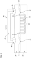
- FIG. 1 shows a first fluid channel 1 for delivering a first fluid and a second fluid channel 2 for delivering a second fluid, wherein first and second fluid channel 1, 2 merge into a single channel 5 before a mixing chamber 10 with an inlet 9 and an outlet 11.
- the mixing chamber 10 comprises perturbation structures 12.
- An outlet fluid channel 13 is arranged behind outlet 11 of the mixing chamber 10 for providing the mixed fluids for further processing in a microfluidic device.
- FIG. 1 shows a central sectional view of the top part of FIG. 1 beginning with the merged fluid channel 5 on the left side.
- the microfluidic device is formed by two parts, a flexible layer 20 which is arranged on top of a substrate 30. Formations between the two parts define fluid channels like the merged fluid channel 5 which is connected to the inlet 9 of the mixing chamber 10 with perturbation structures 12.
- An outlet fluid channel 13 is connected to the outlet 11 of the mixing chamber 10 for guiding the mixed liquids away from the mixing chamber 10.
- FIG. 2 shows the sectional view comparable to the lower part of FIG. 1 with an mechanical actuator 40.
- the mixing chamber 10 with perturbation structures 12 is arranged between the merged fluid channel 5 and the outlet fluid channel 13.
- a mechanical force can be applied to the upper flexible layer 20 by a mechanical actuator 40 so as to deform the flexible layer 20 and thus compress the merged fluid channel 5 and the outlet fluid channel 13 such that a fluid flow between the two points of compression 41, 42 is either inhibited to flow or leave the volume between the points of compression 41, 42 or enter the volume between the points of compression 41, 42.
- the mechanical actuator 40 in FIG. 2 is having two rounded pusher 45 which are linked by a connector 47. It is not necessary that pusher 45 are rounded or linked by a connector 47 but if both pushers shall be pressed in parallel into the flexible layer 20, the mechanical actuator 40 will allow to apply a force only to the connector 47 for moving the pushers 45 into the flexible layer 20. It is also within the scope of the present disclosure that the pushers 45 can be actuated independently from another.
- FIG. 3 shows the same view as FIG. 2 , wherein the dashed line in FIG. 3 indicates that the arrangement of pusher 45 and connector 47 can be moved sidewise so that a movement in the liquid is initiated which is comprised between the first and second point of compression 41, 42. Even the compression of the flexible layer 20 will result in a kind of a peristaltic pressure on the liquid between the two points of compression 41, 42. A repeated sidewise movement or swinging of pusher 45 and connector 47 will enhance the movement of the liquid and thus improve mixing of different liquids forming the liquid between the points of compression 41, 42. The movement of a single one of the pushers 45 alone will also result in a movement of the fluid comprised between the points of compression 41, 42.
- FIG. 4 shows an embodiment of the mixing chamber 10 with inlet and outlet 9, 11 and surrounding channels 1, 2, 5, 13.
- the mixing chamber 10 in FIG. 4 comprises perturbation structures. Mixing will be achieved by compressing flexible layer 20 and possibly moving the actuator (not shown) sidewise.
- the mixing chamber 10 in FIG. 4 is mainly formed in substrate 30.
- FIG. 5 shows an embodiment of the mixing chamber 10 with inlet and outlet 9, 11 and surrounding channels 1, 2, 5, 13 with a mixing chamber 10 that extends laterally but does not have an increased diameter as can be seen in the lower part of FIG. 5 .
- FIG. 6 shows an embodiment of the mixing chamber 10 with inlet and outlet 9, 11 and surrounding channels 1, 2, 5, 13.
- the mixing chamber 10 in FIG. 6 also comprises perturbation structures. Mixing will be achieved by compressing flexible layer 20 and possibly moving the actuator (not shown) sidewise.
- the mixing chamber 10 in FIG. 6 is mainly formed in flexible layer 20.
- FIG. 7 shows an embodiment where the mixing chamber 10 with inlet and outlet 9, 11 and surrounding channels 1, 2, 5, 13 with a mixing chamber 10 is simply a part of the channel and does not have an increased diameter in any direction compared to merged fluid channel 5 and outlet fluid channel 13 as can be seen in the lower part of FIG. 7 .
- FIG. 8 shows an embodiment where the mixing chamber 10 with inlet and outlet 9, 11 and surrounding channels 1, 2, 5, 13 with a mixing chamber 10 is simply a part of the channel and comprises perturbation structure 12 but does not have an increased diameter in any direction compared to merged fluid channel 5 and outlet fluid channel 13 as can be seen in the lower part of FIG. 8 .
- the perturbation structures in the mixing chamber are intended to impede the fluid flow. For that reason, formations are envisaged which are arranged perpendicular to the fluid flow direction.
- the perturbation structures comprise pillars, walls or tubes which are connected to the upper or lower inner surface of the mixing chamber.
Landscapes
- Chemical & Material Sciences (AREA)
- Chemical Kinetics & Catalysis (AREA)
- Health & Medical Sciences (AREA)
- Dispersion Chemistry (AREA)
- Analytical Chemistry (AREA)
- General Health & Medical Sciences (AREA)
- Hematology (AREA)
- Clinical Laboratory Science (AREA)
Claims (12)
- Ein mikrofluidischer Mischer, der aus zwei Teilen gebildet ist, wobei ein erster Teil ein Substrat (30) ist, das Formationen aufweist, die Fluidkanäle auf einer äußeren Oberfläche definieren, die zu einem zweiten Teil gerichtet ist, der eine flexible Schicht (20) ist, wobei die flexible Schicht (20) Formationen aufweist, die Fluidkanäle definieren, die, wenn die flexible Schicht (20) über dem Substrat (30) so positioniert ist, dass sie die Fluidkanäle des Substrats (30) bedeckt, um einen Fluidverbindungspfad bereitzustellen, wobei ein Abschnitt des Verbindungspfads mindestens einen ersten und einen zweiten Fluidkanal (1, 2) zum Bereitstellen eines ersten und eines zweiten Fluids umfasst, wobei der erste und der zweite Fluidkanal (1, 2) vor einem Einlass (9) einer Mischkammer (10) in einen vereinigten Fluidkanal (5) übergehen, wobei die Mischkammer (10) Störungsformationen (12) umfasst und ein Auslass (11) der Mischkammer (10) mit einem Auslassfluidkanal (13) verbunden ist, wobei die flexible Schicht (20) Punkte zur Kompression (41, 42) am Einlass und Auslass (9, 11) der Mischkammer (10) zum Verschließen des zusammengeführten Fluidkanals (5) und des Auslassfluidkanals (13), der mit dem Einlass und dem Auslass (9, 11) der Mischkammer (10) verbunden ist, dadurch gekennzeichnet, dass Störungsformationen (12) der Mischkammer (10) vertikal angeordnete Wände, Säulen oder Rohre in Bezug auf eine innere Oberfläche sind.
- Der mikrofluidische Mischer nach Anspruch 1, wobei die Störungsformationen (12) in der Mischkammer (10) senkrecht zur Strömungsrichtung eines Fluids angeordnet sind und die Störungsformationen (12) mit mindestens einer Innenfläche der Mischkammer (10) verbunden sind.
- Der mikrofluidische Mischer nach einem der Ansprüche 1 bis 2, wobei der die Mischkammer (10) aufweisende Abschnitt beidseitig ein Betätigungselement (40) zur Verformung der flexiblen Schicht (20) aufweist.
- Der mikrofluidische Mischer nach einem der vorhergehenden Ansprüche, wobei weitere Kanäle, die durch Substrat (30) und flexible Schicht (20) gebildet werden, vor dem Einlass (9) der Mischkammer (10) in den zusammengeführten Fluidkanal (5) übergehen.
- Der mikrofluidische Mischer nach einem der vorhergehenden Ansprüche, bei dem der Auslasskanal (13) in eine Vielzahl von Kanälen aufgeteilt ist.
- Der mikrofluidische Mischer nach einem der vorhergehenden Ansprüche, wobei das Substrat (30) aus einem starren Material hergestellt ist.
- Eine mikrofluidische Vorrichtung mit mindestens einem mikrofluidischen Mischer nach einem der Ansprüche 1 bis 6.
- Ein System mit einer mikrofluidischen Vorrichtung nach Anspruch 7 und mindestens einem mechanischen Aktuator (40), der oberhalb der Kompressionspunkte (41, 42) eines mikrofluidischen Mischers an dessen Einlass und Auslass (9, 11) angeordnet ist.
- Ein Verfahren zum Mischen eines Fluids in einer mikrofluidischen Vorrichtung, das die folgenden Schritte umfasst:- Einführen von mindestens zwei verschiedenen Flüssigkeiten zum Mischen in einen ersten und einen zweiten Fluidkanal (1, 2) in einem mikrofluidischen Mischer, der aus zwei Teilen gebildet ist, wobei ein erster Teil ein Substrat (30) mit Formationen ist, die Fluidkanäle auf einer äußeren Oberfläche definieren, die zu einem zweiten Teil gerichtet ist, der eine flexible Schicht (20) ist, wobei die flexible Schicht Formationen aufweist, die einen ersten und einen zweiten Fluidkanal (1, 2) definieren, die, wenn die flexible Schicht (20) über dem Substrat (30) so positioniert ist, dass sie die Fluidkanäle des Substrats (30) bedeckt, um einen Fluidverbindungspfad bereitzustellen, wobei in einem Abschnitt des Verbindungspfads der erste und der zweite Fluidkanal (1, 2) vor einem Einlass (9) einer Mischkammer (10) zu einem zusammengeführten Fluidkanal (5) verschmelzen, wobei die Mischkammer (10) Störungsformationen (12) umfasst und ein Auslass (11) der Mischkammer (10) mit einem Auslassfluidkanal (13) verbunden ist,- mindestens einmaliges Anlegen eines mechanischen Drucks an Kompressionspunkten (41, 42) am Einlass (9) und am Auslass (11) der Mischkammer (10) zum Schließen der mit dem Einlass (9) und dem Auslass (11) der Mischkammer (10) verbundenen Kanäle und zum Mischen der Fluide;- den mechanischen Druck zu entlasten, damit die gemischten Flüssigkeiten die Mischkammer durch den Auslass (11) verlassen können,dadurch gekennzeichnet, dass Störungsformationen (12) der Mischkammer (10) vertikal angeordnete Wände, Säulen oder Rohre in Bezug auf eine Innenfläche sind.
- Das Verfahren nach Anspruch 9, wobei die mechanische Kraft auf die Druckpunkte (41, 42) parallel zu beiden Druckpunkten aufgebracht wird.
- Das Verfahren nach einem der Ansprüche 9 oder 10, wobei ein mechanischer Aktuator (40) zum Aufbringen der mechanischen Kraft auf die Druckpunkte (41, 42) verwendet wird.
- Das Verfahren nach einem der Ansprüche 9 bis 11, wobei die Druckpunkte (41, 42) nach Aufbringen der mechanischen Kraft seitlich betätigt werden.
Applications Claiming Priority (1)
| Application Number | Priority Date | Filing Date | Title |
|---|---|---|---|
| LU102865A LU102865B1 (en) | 2021-10-14 | 2021-10-14 | Microfluidic mixer |
Publications (2)
| Publication Number | Publication Date |
|---|---|
| EP4166227A1 EP4166227A1 (de) | 2023-04-19 |
| EP4166227B1 true EP4166227B1 (de) | 2024-10-30 |
Family
ID=79185682
Family Applications (1)
| Application Number | Title | Priority Date | Filing Date |
|---|---|---|---|
| EP22194732.8A Active EP4166227B1 (de) | 2021-10-14 | 2022-09-09 | Mikrofluidischer mischer und verfahren |
Country Status (3)
| Country | Link |
|---|---|
| US (1) | US20230122655A1 (de) |
| EP (1) | EP4166227B1 (de) |
| LU (1) | LU102865B1 (de) |
Family Cites Families (18)
| Publication number | Priority date | Publication date | Assignee | Title |
|---|---|---|---|---|
| US5595712A (en) * | 1994-07-25 | 1997-01-21 | E. I. Du Pont De Nemours And Company | Chemical mixing and reaction apparatus |
| US6939032B2 (en) * | 2001-10-25 | 2005-09-06 | Erie Scientific Company | Cover slip mixing apparatus |
| GB0304033D0 (en) * | 2003-02-21 | 2003-03-26 | Imp College Innovations Ltd | Apparatus |
| US7588671B2 (en) * | 2003-11-21 | 2009-09-15 | Ebara Corporation | Microfluidic treatment method and device |
| US20050272144A1 (en) * | 2004-06-08 | 2005-12-08 | Konica Minolta Medical & Graphic, Inc. | Micro-reactor for improving efficiency of liquid mixing and reaction |
| JP2007090138A (ja) * | 2005-09-27 | 2007-04-12 | Yokogawa Electric Corp | 化学処理用カートリッジおよびその使用方法 |
| US20100075109A1 (en) * | 2006-10-31 | 2010-03-25 | Makoto Takagi | Microchip, Molding Die and Electroforming Master |
| JP5484909B2 (ja) * | 2006-12-14 | 2014-05-07 | ベーリンガー インゲルハイム マイクロパーツ ゲゼルシャフト ミット ベシュレンクテル ハフツング | 液体の吸入又は操作のための器具 |
| KR101959447B1 (ko) * | 2012-04-06 | 2019-03-18 | 삼성전자주식회사 | 시료 중의 표적물질을 효율적으로 처리하는 방법 |
| US9987576B2 (en) * | 2012-12-10 | 2018-06-05 | University Of Virginia Patent Foundation | Frequency-based filtering of mechanical actuation using fluidic device |
| US9463460B2 (en) * | 2014-06-23 | 2016-10-11 | Indian Institute Of Science | Microfluidic device |
| WO2017011862A1 (en) * | 2015-07-17 | 2017-01-26 | Axxin Pty Ltd | Diagnostic test assembly, apparatus, method |
| US10377538B2 (en) * | 2015-12-01 | 2019-08-13 | Illumina, Inc. | Liquid storage and delivery mechanisms and methods |
| WO2018009764A1 (en) * | 2016-07-08 | 2018-01-11 | CLiCS, LLC | Dye dispensing system |
| EP3270018A1 (de) | 2016-07-13 | 2018-01-17 | Stratec Consumables GmbH | Mikrofluidische flusssteuerung und -vorrichtung |
| US11548000B2 (en) * | 2018-11-28 | 2023-01-10 | International Business Machines Corporation | Structures for automated, multi-stage processing of nanofluidic chips |
| JP7278932B2 (ja) * | 2019-12-09 | 2023-05-22 | 富士フイルム株式会社 | 検査用容器 |
| CN112269023B (zh) * | 2020-08-07 | 2023-11-21 | 宁波大学 | 微流控拉曼芯片及基于微流控拉曼芯片检测血液中外泌体的方法 |
-
2021
- 2021-10-14 LU LU102865A patent/LU102865B1/en active IP Right Grant
-
2022
- 2022-09-08 US US17/940,443 patent/US20230122655A1/en active Pending
- 2022-09-09 EP EP22194732.8A patent/EP4166227B1/de active Active
Also Published As
| Publication number | Publication date |
|---|---|
| EP4166227A1 (de) | 2023-04-19 |
| LU102865B1 (en) | 2023-04-21 |
| US20230122655A1 (en) | 2023-04-20 |
Similar Documents
| Publication | Publication Date | Title |
|---|---|---|
| US8425863B2 (en) | Micro fluidic device | |
| EP2606975B1 (de) | Mikrofluidische Vorrichtung mit Flüssigkeitsmess-Ladesystem für eine mikrofluidische Vorrichtung | |
| EP2606242B1 (de) | Mikrofluidikvorrichtungen mit mechanisch abgedichteten membranventilen | |
| US9151409B2 (en) | Device and method for controlling fluid flows in lab-on-a-chip systems and method for producing device | |
| US7588671B2 (en) | Microfluidic treatment method and device | |
| KR20050063358A (ko) | 미소 유체 제어소자 및 미소 유체의 제어 방법 | |
| US20110315227A1 (en) | Microfluidic system and method | |
| US20070286739A1 (en) | Apparatus for driving microfluid and driving method thereof | |
| US20120141999A1 (en) | Gene analysis apparatus and gene analysis method using the same | |
| AU5773400A (en) | Microfabricated elastomeric valve and pump systems | |
| EP2847465B1 (de) | Mikrofluidische pumpe | |
| CN102665915A (zh) | 具有平行气动界面板的微流体模块 | |
| CN101500709A (zh) | 用于加工、控制和/或检测流体样品并有减小的死体积的流体样品输送装置 | |
| CN107620804A (zh) | 流体控制装置 | |
| Churski et al. | Droplet on demand system utilizing a computer controlled microvalve integrated into a stiff polymeric microfluidic device | |
| EP3763439A1 (de) | Mikrofluidischer chip und ventil, herstellungsverfahren und verwendungen | |
| JP2003240757A (ja) | マイクロ化学チップ | |
| JP2014163713A (ja) | 生化学用カートリッジおよび生化学用送液システム | |
| Mohammadzadeh et al. | Rapid and inexpensive method for fabrication of multi-material multi-layer microfluidic devices | |
| KR100444751B1 (ko) | 표면장력에 의한 유체제어 소자 | |
| EP4166227A1 (de) | Mikrofluidischer mischer und verfahren | |
| CN117940216A (zh) | 微流体装置和用于运行微流体装置的方法 | |
| 김태정 | Fluid-dynamic strategies for particle manipulation near fluid-solid interfaces | |
| Peyman et al. | Evaluation of pressure changes for capillary and fishbone valves in lab-on-CD systems | |
| CN119746968A (zh) | 生成浓度梯度液滴的微流控芯片及浓度梯度液滴生成方法 |
Legal Events
| Date | Code | Title | Description |
|---|---|---|---|
| PUAI | Public reference made under article 153(3) epc to a published international application that has entered the european phase |
Free format text: ORIGINAL CODE: 0009012 |
|
| STAA | Information on the status of an ep patent application or granted ep patent |
Free format text: STATUS: REQUEST FOR EXAMINATION WAS MADE |
|
| 17P | Request for examination filed |
Effective date: 20230220 |
|
| AK | Designated contracting states |
Kind code of ref document: A1 Designated state(s): AL AT BE BG CH CY CZ DE DK EE ES FI FR GB GR HR HU IE IS IT LI LT LU LV MC MK MT NL NO PL PT RO RS SE SI SK SM TR |
|
| STAA | Information on the status of an ep patent application or granted ep patent |
Free format text: STATUS: EXAMINATION IS IN PROGRESS |
|
| 17Q | First examination report despatched |
Effective date: 20230607 |
|
| P01 | Opt-out of the competence of the unified patent court (upc) registered |
Effective date: 20230711 |
|
| GRAP | Despatch of communication of intention to grant a patent |
Free format text: ORIGINAL CODE: EPIDOSNIGR1 |
|
| STAA | Information on the status of an ep patent application or granted ep patent |
Free format text: STATUS: GRANT OF PATENT IS INTENDED |
|
| GRAS | Grant fee paid |
Free format text: ORIGINAL CODE: EPIDOSNIGR3 |
|
| INTG | Intention to grant announced |
Effective date: 20240718 |
|
| GRAA | (expected) grant |
Free format text: ORIGINAL CODE: 0009210 |
|
| STAA | Information on the status of an ep patent application or granted ep patent |
Free format text: STATUS: THE PATENT HAS BEEN GRANTED |
|
| AK | Designated contracting states |
Kind code of ref document: B1 Designated state(s): AL AT BE BG CH CY CZ DE DK EE ES FI FR GB GR HR HU IE IS IT LI LT LU LV MC MK MT NL NO PL PT RO RS SE SI SK SM TR |
|
| REG | Reference to a national code |
Ref country code: GB Ref legal event code: FG4D |
|
| REG | Reference to a national code |
Ref country code: CH Ref legal event code: EP |
|
| REG | Reference to a national code |
Ref country code: IE Ref legal event code: FG4D |
|
| REG | Reference to a national code |
Ref country code: DE Ref legal event code: R096 Ref document number: 602022007211 Country of ref document: DE |
|
| REG | Reference to a national code |
Ref country code: LT Ref legal event code: MG9D |
|
| REG | Reference to a national code |
Ref country code: NL Ref legal event code: MP Effective date: 20241030 |
|
| PG25 | Lapsed in a contracting state [announced via postgrant information from national office to epo] |
Ref country code: HR Free format text: LAPSE BECAUSE OF FAILURE TO SUBMIT A TRANSLATION OF THE DESCRIPTION OR TO PAY THE FEE WITHIN THE PRESCRIBED TIME-LIMIT Effective date: 20241030 Ref country code: IS Free format text: LAPSE BECAUSE OF FAILURE TO SUBMIT A TRANSLATION OF THE DESCRIPTION OR TO PAY THE FEE WITHIN THE PRESCRIBED TIME-LIMIT Effective date: 20250228 Ref country code: PT Free format text: LAPSE BECAUSE OF FAILURE TO SUBMIT A TRANSLATION OF THE DESCRIPTION OR TO PAY THE FEE WITHIN THE PRESCRIBED TIME-LIMIT Effective date: 20250228 |
|
| PG25 | Lapsed in a contracting state [announced via postgrant information from national office to epo] |
Ref country code: NL Free format text: LAPSE BECAUSE OF FAILURE TO SUBMIT A TRANSLATION OF THE DESCRIPTION OR TO PAY THE FEE WITHIN THE PRESCRIBED TIME-LIMIT Effective date: 20241030 Ref country code: FI Free format text: LAPSE BECAUSE OF FAILURE TO SUBMIT A TRANSLATION OF THE DESCRIPTION OR TO PAY THE FEE WITHIN THE PRESCRIBED TIME-LIMIT Effective date: 20241030 |
|
| REG | Reference to a national code |
Ref country code: AT Ref legal event code: MK05 Ref document number: 1736380 Country of ref document: AT Kind code of ref document: T Effective date: 20241030 |
|
| PG25 | Lapsed in a contracting state [announced via postgrant information from national office to epo] |
Ref country code: BG Free format text: LAPSE BECAUSE OF FAILURE TO SUBMIT A TRANSLATION OF THE DESCRIPTION OR TO PAY THE FEE WITHIN THE PRESCRIBED TIME-LIMIT Effective date: 20241030 |
|
| PG25 | Lapsed in a contracting state [announced via postgrant information from national office to epo] |
Ref country code: ES Free format text: LAPSE BECAUSE OF FAILURE TO SUBMIT A TRANSLATION OF THE DESCRIPTION OR TO PAY THE FEE WITHIN THE PRESCRIBED TIME-LIMIT Effective date: 20241030 |
|
| PG25 | Lapsed in a contracting state [announced via postgrant information from national office to epo] |
Ref country code: NO Free format text: LAPSE BECAUSE OF FAILURE TO SUBMIT A TRANSLATION OF THE DESCRIPTION OR TO PAY THE FEE WITHIN THE PRESCRIBED TIME-LIMIT Effective date: 20250130 |
|
| PG25 | Lapsed in a contracting state [announced via postgrant information from national office to epo] |
Ref country code: AT Free format text: LAPSE BECAUSE OF FAILURE TO SUBMIT A TRANSLATION OF THE DESCRIPTION OR TO PAY THE FEE WITHIN THE PRESCRIBED TIME-LIMIT Effective date: 20241030 Ref country code: GR Free format text: LAPSE BECAUSE OF FAILURE TO SUBMIT A TRANSLATION OF THE DESCRIPTION OR TO PAY THE FEE WITHIN THE PRESCRIBED TIME-LIMIT Effective date: 20250131 Ref country code: LV Free format text: LAPSE BECAUSE OF FAILURE TO SUBMIT A TRANSLATION OF THE DESCRIPTION OR TO PAY THE FEE WITHIN THE PRESCRIBED TIME-LIMIT Effective date: 20241030 |
|
| PG25 | Lapsed in a contracting state [announced via postgrant information from national office to epo] |
Ref country code: PL Free format text: LAPSE BECAUSE OF FAILURE TO SUBMIT A TRANSLATION OF THE DESCRIPTION OR TO PAY THE FEE WITHIN THE PRESCRIBED TIME-LIMIT Effective date: 20241030 |
|
| PG25 | Lapsed in a contracting state [announced via postgrant information from national office to epo] |
Ref country code: RS Free format text: LAPSE BECAUSE OF FAILURE TO SUBMIT A TRANSLATION OF THE DESCRIPTION OR TO PAY THE FEE WITHIN THE PRESCRIBED TIME-LIMIT Effective date: 20250130 |
|
| PG25 | Lapsed in a contracting state [announced via postgrant information from national office to epo] |
Ref country code: SM Free format text: LAPSE BECAUSE OF FAILURE TO SUBMIT A TRANSLATION OF THE DESCRIPTION OR TO PAY THE FEE WITHIN THE PRESCRIBED TIME-LIMIT Effective date: 20241030 |
|
| PG25 | Lapsed in a contracting state [announced via postgrant information from national office to epo] |
Ref country code: DK Free format text: LAPSE BECAUSE OF FAILURE TO SUBMIT A TRANSLATION OF THE DESCRIPTION OR TO PAY THE FEE WITHIN THE PRESCRIBED TIME-LIMIT Effective date: 20241030 |
|
| PG25 | Lapsed in a contracting state [announced via postgrant information from national office to epo] |
Ref country code: EE Free format text: LAPSE BECAUSE OF FAILURE TO SUBMIT A TRANSLATION OF THE DESCRIPTION OR TO PAY THE FEE WITHIN THE PRESCRIBED TIME-LIMIT Effective date: 20241030 |
|
| PG25 | Lapsed in a contracting state [announced via postgrant information from national office to epo] |
Ref country code: RO Free format text: LAPSE BECAUSE OF FAILURE TO SUBMIT A TRANSLATION OF THE DESCRIPTION OR TO PAY THE FEE WITHIN THE PRESCRIBED TIME-LIMIT Effective date: 20241030 |
|
| PG25 | Lapsed in a contracting state [announced via postgrant information from national office to epo] |
Ref country code: SK Free format text: LAPSE BECAUSE OF FAILURE TO SUBMIT A TRANSLATION OF THE DESCRIPTION OR TO PAY THE FEE WITHIN THE PRESCRIBED TIME-LIMIT Effective date: 20241030 |
|
| PG25 | Lapsed in a contracting state [announced via postgrant information from national office to epo] |
Ref country code: CZ Free format text: LAPSE BECAUSE OF FAILURE TO SUBMIT A TRANSLATION OF THE DESCRIPTION OR TO PAY THE FEE WITHIN THE PRESCRIBED TIME-LIMIT Effective date: 20241030 |
|
| REG | Reference to a national code |
Ref country code: DE Ref legal event code: R097 Ref document number: 602022007211 Country of ref document: DE |
|
| PLBE | No opposition filed within time limit |
Free format text: ORIGINAL CODE: 0009261 |
|
| STAA | Information on the status of an ep patent application or granted ep patent |
Free format text: STATUS: NO OPPOSITION FILED WITHIN TIME LIMIT |
|
| PG25 | Lapsed in a contracting state [announced via postgrant information from national office to epo] |
Ref country code: SE Free format text: LAPSE BECAUSE OF FAILURE TO SUBMIT A TRANSLATION OF THE DESCRIPTION OR TO PAY THE FEE WITHIN THE PRESCRIBED TIME-LIMIT Effective date: 20241030 |
|
| REG | Reference to a national code |
Ref country code: CH Ref legal event code: U11 Free format text: ST27 STATUS EVENT CODE: U-0-0-U10-U11 (AS PROVIDED BY THE NATIONAL OFFICE) Effective date: 20251001 |
|
| 26N | No opposition filed |
Effective date: 20250731 |
|
| PGFP | Annual fee paid to national office [announced via postgrant information from national office to epo] |
Ref country code: DE Payment date: 20250919 Year of fee payment: 4 |
|
| PGFP | Annual fee paid to national office [announced via postgrant information from national office to epo] |
Ref country code: FR Payment date: 20250925 Year of fee payment: 4 |
|
| PGFP | Annual fee paid to national office [announced via postgrant information from national office to epo] |
Ref country code: IT Payment date: 20250930 Year of fee payment: 4 |
|
| PGFP | Annual fee paid to national office [announced via postgrant information from national office to epo] |
Ref country code: CH Payment date: 20251001 Year of fee payment: 4 |