EP4165317B1 - Frein a disque equipe d'une piece autonome de protection d'un connecteur electrique de motoreducteur - Google Patents
Frein a disque equipe d'une piece autonome de protection d'un connecteur electrique de motoreducteur Download PDFInfo
- Publication number
- EP4165317B1 EP4165317B1 EP21737717.5A EP21737717A EP4165317B1 EP 4165317 B1 EP4165317 B1 EP 4165317B1 EP 21737717 A EP21737717 A EP 21737717A EP 4165317 B1 EP4165317 B1 EP 4165317B1
- Authority
- EP
- European Patent Office
- Prior art keywords
- electrical connector
- brake
- extension
- guides
- pin
- Prior art date
- Legal status (The legal status is an assumption and is not a legal conclusion. Google has not performed a legal analysis and makes no representation as to the accuracy of the status listed.)
- Active
Links
Images

Classifications
-
- F—MECHANICAL ENGINEERING; LIGHTING; HEATING; WEAPONS; BLASTING
- F16—ENGINEERING ELEMENTS AND UNITS; GENERAL MEASURES FOR PRODUCING AND MAINTAINING EFFECTIVE FUNCTIONING OF MACHINES OR INSTALLATIONS; THERMAL INSULATION IN GENERAL
- F16D—COUPLINGS FOR TRANSMITTING ROTATION; CLUTCHES; BRAKES
- F16D55/00—Brakes with substantially-radial braking surfaces pressed together in axial direction, e.g. disc brakes
- F16D55/02—Brakes with substantially-radial braking surfaces pressed together in axial direction, e.g. disc brakes with axially-movable discs or pads pressed against axially-located rotating members
- F16D55/22—Brakes with substantially-radial braking surfaces pressed together in axial direction, e.g. disc brakes with axially-movable discs or pads pressed against axially-located rotating members by clamping an axially-located rotating disc between movable braking members, e.g. movable brake discs or brake pads
- F16D55/224—Brakes with substantially-radial braking surfaces pressed together in axial direction, e.g. disc brakes with axially-movable discs or pads pressed against axially-located rotating members by clamping an axially-located rotating disc between movable braking members, e.g. movable brake discs or brake pads with a common actuating member for the braking members
- F16D55/225—Brakes with substantially-radial braking surfaces pressed together in axial direction, e.g. disc brakes with axially-movable discs or pads pressed against axially-located rotating members by clamping an axially-located rotating disc between movable braking members, e.g. movable brake discs or brake pads with a common actuating member for the braking members the braking members being brake pads
- F16D55/226—Brakes with substantially-radial braking surfaces pressed together in axial direction, e.g. disc brakes with axially-movable discs or pads pressed against axially-located rotating members by clamping an axially-located rotating disc between movable braking members, e.g. movable brake discs or brake pads with a common actuating member for the braking members the braking members being brake pads in which the common actuating member is moved axially, e.g. floating caliper disc brakes
-
- F—MECHANICAL ENGINEERING; LIGHTING; HEATING; WEAPONS; BLASTING
- F16—ENGINEERING ELEMENTS AND UNITS; GENERAL MEASURES FOR PRODUCING AND MAINTAINING EFFECTIVE FUNCTIONING OF MACHINES OR INSTALLATIONS; THERMAL INSULATION IN GENERAL
- F16D—COUPLINGS FOR TRANSMITTING ROTATION; CLUTCHES; BRAKES
- F16D55/00—Brakes with substantially-radial braking surfaces pressed together in axial direction, e.g. disc brakes
- F16D55/02—Brakes with substantially-radial braking surfaces pressed together in axial direction, e.g. disc brakes with axially-movable discs or pads pressed against axially-located rotating members
- F16D55/22—Brakes with substantially-radial braking surfaces pressed together in axial direction, e.g. disc brakes with axially-movable discs or pads pressed against axially-located rotating members by clamping an axially-located rotating disc between movable braking members, e.g. movable brake discs or brake pads
- F16D55/224—Brakes with substantially-radial braking surfaces pressed together in axial direction, e.g. disc brakes with axially-movable discs or pads pressed against axially-located rotating members by clamping an axially-located rotating disc between movable braking members, e.g. movable brake discs or brake pads with a common actuating member for the braking members
- F16D55/225—Brakes with substantially-radial braking surfaces pressed together in axial direction, e.g. disc brakes with axially-movable discs or pads pressed against axially-located rotating members by clamping an axially-located rotating disc between movable braking members, e.g. movable brake discs or brake pads with a common actuating member for the braking members the braking members being brake pads
- F16D55/226—Brakes with substantially-radial braking surfaces pressed together in axial direction, e.g. disc brakes with axially-movable discs or pads pressed against axially-located rotating members by clamping an axially-located rotating disc between movable braking members, e.g. movable brake discs or brake pads with a common actuating member for the braking members the braking members being brake pads in which the common actuating member is moved axially, e.g. floating caliper disc brakes
- F16D55/2265—Brakes with substantially-radial braking surfaces pressed together in axial direction, e.g. disc brakes with axially-movable discs or pads pressed against axially-located rotating members by clamping an axially-located rotating disc between movable braking members, e.g. movable brake discs or brake pads with a common actuating member for the braking members the braking members being brake pads in which the common actuating member is moved axially, e.g. floating caliper disc brakes the axial movement being guided by one or more pins engaging bores in the brake support or the brake housing
- F16D55/22655—Constructional details of guide pins
-
- F—MECHANICAL ENGINEERING; LIGHTING; HEATING; WEAPONS; BLASTING
- F16—ENGINEERING ELEMENTS AND UNITS; GENERAL MEASURES FOR PRODUCING AND MAINTAINING EFFECTIVE FUNCTIONING OF MACHINES OR INSTALLATIONS; THERMAL INSULATION IN GENERAL
- F16D—COUPLINGS FOR TRANSMITTING ROTATION; CLUTCHES; BRAKES
- F16D2121/00—Type of actuator operation force
- F16D2121/18—Electric or magnetic
- F16D2121/24—Electric or magnetic using motors
-
- F—MECHANICAL ENGINEERING; LIGHTING; HEATING; WEAPONS; BLASTING
- F16—ENGINEERING ELEMENTS AND UNITS; GENERAL MEASURES FOR PRODUCING AND MAINTAINING EFFECTIVE FUNCTIONING OF MACHINES OR INSTALLATIONS; THERMAL INSULATION IN GENERAL
- F16D—COUPLINGS FOR TRANSMITTING ROTATION; CLUTCHES; BRAKES
- F16D2131/00—Overall arrangement of the actuators or their elements, e.g. modular construction
-
- F—MECHANICAL ENGINEERING; LIGHTING; HEATING; WEAPONS; BLASTING
- F16—ENGINEERING ELEMENTS AND UNITS; GENERAL MEASURES FOR PRODUCING AND MAINTAINING EFFECTIVE FUNCTIONING OF MACHINES OR INSTALLATIONS; THERMAL INSULATION IN GENERAL
- F16D—COUPLINGS FOR TRANSMITTING ROTATION; CLUTCHES; BRAKES
- F16D2250/00—Manufacturing; Assembly
- F16D2250/0007—Casting
Definitions
- the invention relates to a disc brake comprising an independent part for protecting an electrical connector of a gear motor integrated into the brake.
- Some brakes are equipped with a gear motor mounted on the brake casing itself.
- the electric motor is powered by an electrical connector protruding from the gearmotor housing.
- This electrical connector is a weak part, and vulnerable to shocks that can be produced accidentally by projections of stones, gravel, by accumulations of mud, ice on the wheel in bad weather, and that the rotation of the wheel causes the brake, or even by clumsy assembly or disassembly of the wheel or brake. We therefore took care to protect this connector.
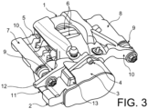
- FIG. 3 In an existing design, shown in Figure 3 , we have shown a disc brake and floating caliper of which a caliper bears the reference 1, a geared motor the reference 2, and where a housing 3 of the geared motor 2 is mounted on one face of the envelope of the caliper 1 by means of screw 4.
- the brake also includes a yoke 5 for guiding the movements of the pads 6 actuated by the stirrup 1.
- the yoke 5 comprises in particular two parallel columns 7 and 8 on either side of the stirrup 1 with two lateral edges of the brake and which extend almost as far as the gear motor 2.
- the envelope of the caliper 1 has a complex shape, especially since it includes connecting tabs 10 which project in opposite lateral directions to receive threaded rods 9 protruding from the columns 7 and 8 and thus connect the stirrup 1 to the yoke 5.
- the geared motor 2 comprises an electrical connector 11 projecting outside the housing 3, and at a lateral edge of the brake being adjacent to the part of the stirrup 1 close to the mounting face of the gear motor 2, and also adjacent to the threaded rod 9 of one of the columns 7 and to the associated connecting tab 10.
- the protection of the electrical connector 11, advantageous or even necessary against the risks of shock, can be ensured, according to the known art, by an extension 12 in the lateral direction of the brake (perpendicular to the columns 7 and 8) of the tab connection 10 associated with the column 7, in order to directly cover the electrical connector 11 and to protect it from certain shocks; another device for protecting the electrical connector 11 is constituted by a flyweight 13, established projecting from the connecting tab 10, of slender shape and extending in the direction of the columns 7 and 8 at the height of the connector 11, and here at also height of the housing 3. Its function is to break the accumulations of mud, ice which could reach the electrical connector 11 during the movement of the wheel which is applied by the brake.
- the weight 13 and the extension 12 of the connecting tab 10 further complicate the design of the envelope of the stirrup 1.
- the extension of one of the connecting tabs 10, imposed by the flyweight 13 in the direction of extension of the columns 7 and 8 and by the extension 12 in the lateral direction causes significant manufacturing difficulties because of the risks of failure to cast this irregular, long and fairly thin part of the envelope.
- the need to protect the electrical connector 11 from shocks therefore results in an unfavorable design of the casing of the stirrup 1.
- a general aspect of the invention is a disc brake comprising an outer caliper casing manufactured by molding, a gear motor attached to the casing and including an electrical connector which extends out of a housing of the gear motor and out of the casing. envelope, a yoke for guiding braking pads, the yoke comprising parallel columns, the electrical connector being adjacent to one of the columns, the columns containing rods projecting from one of their ends, the envelope comprising connecting lugs receiving the rods so as to connect the caliper to the yoke, comprising a protective part manufactured separately from the casing and the housing, attached to the brake and covering the electrical connector in a potential path of external bodies, such as stones, mud or ice , likely to strike the electrical connector, the rod of said one of the posts being provided with respect to the rod of the other posts, with an extension, directed towards the geared motor, and the protective part of the electrical connector is mounted on said extension, characterized in that said extension extends at the height of the electrical connector in the direction of the length of the
- the caliper casing is therefore easier to produce by molding.
- the protective part can much more easily be given any advantageous shape to accomplish its function.
- it is not essential that it be manufactured by molding: on the contrary, it may be a rigid metallic part (or another material), cut, deformed or machined by any process known to give it without difficulty in manufacturing a possibly complicated shape, and chosen to best cover the electrical connector.
- Another important point of the invention is that the rod fitted to one of the columns is used to fix the protective part, by extending this rod a little: the increase in weight due to the support is very reduced.
- the protective part is, in an important embodiment of the invention, a tube which is engaged on the threaded rod, for example by screwing; in another important embodiment, it comprises a rigid strip of sinuous shape, shaped to best cover the connector, and which can also be screwed or bolted to the threaded rod.
- the rigid strip advantageously comprises a first branch which extends against the housing moving away from the envelope from a place of attachment to the threaded rod, the external bodies against which it is envisaged to be protect being accumulations of mud, ice likely to be dragged or projected by a vehicle wheel equipped with the brake.
- It can just as advantageously comprise a branch approaching the electrical connector from the threaded rod, then comprising at least one fold parallel to the columns extending in front of the electrical connector, so as to cover a complete surface in front of the connector. It can also advantageously be a single part comprising two branches diverging from a common location for fixing to the brake and conforming to the above.
- the protective part according to the invention can therefore take very diverse shapes and aspects, while being distinguishable from other parts or equipment attached to the brake by screwing or otherwise in that it is a rigid and inert structure, with no other function than to cover the electrical connector, either by extending directly in front of it, or at a certain distance when the path of the body responsible for an impact can be predicted, as for a block of mud or ice driven by the wheel.
- the threaded rod (9) of the other column 8 is not modified and is therefore shorter than the threaded rod 15.
- a sinuous and rigid metal strip here forms the protective part 17 of the connector 11. It includes an eyelet 18 which is threaded into the extension 16 of the threaded rod 15. A nut 19 is screwed onto the extension 16 and retains the protective part 17 against a nut 20 already present in the known brake, screwed onto the column 15 to immobilize it on the connecting tab 10.
- the protective part 17 comprises two branches on either side of the eyelet 18.
- One of the branches 21 first extends perpendicular to the threaded rod 15 moving away from the electrical connector 11, then, after an elbow , parallel to the threaded rod 15, forming a bar 22 which extends above the connecting tab 10 (crossing it) and at the height of the connector 11 in the direction of the columns 7 and 8.
- the bar 22 parallel to columns 7 and 8 serves as an icebreaker. We see that it can easily be arranged in another location than the flyweight 13, both in the direction of the columns 7 and 8 and in a direction perpendicular to them and to the main direction of extension of the connecting tab 10: it can therefore be placed clearly at a distance from the latter, if this is advantageous.
- the branch 23 opposite the branch 21 also extends first perpendicular to the direction of the columns 7 and 8 but towards the electrical connector 11, then it comprises, after an elbow, a first fold 24, then a second fold 25 after a double right angle elbow.
- the folds 24 and 25 are parallel to the columns 7 and 8 and opposite each other, and they cover an entire protective surface of the electrical connector 11 at the location of the extension 12, but with an extension wider than him in the direction of columns 7 and 8 and therefore better efficiency.
- the independent protective part can be produced in many other ways, for example formed of a profile, a rod, a plate, a grid, etc. It is either unitary or composed of a plurality of distinct parts.
- the brake it can be of any type, for example a dynamic brake or a parking brake.
- the location of the protective part or independent protective parts may be different on the brake, depending on the position of the electrical connector and the position and orientation of the brake in the vehicle, which determine the predictable paths of bodies potentially responsible for shocks; the protective parts extend, in the major embodiments shown here, on the face of the brake opposite the shoes 6.
Landscapes
- Engineering & Computer Science (AREA)
- General Engineering & Computer Science (AREA)
- Mechanical Engineering (AREA)
- Braking Arrangements (AREA)
- Braking Systems And Boosters (AREA)
Description
- L'invention se rapporte à un frein à disque comprenant une pièce autonome de protection d'un connecteur électrique d'un motoréducteur intégré au frein.
- Certains freins sont équipés d'un motoréducteur monté sur l'enveloppe du frein proprement dit. L'alimentation du moteur électrique se fait par un connecteur électrique saillant hors du boîtier du motoréducteur. Ce connecteur électrique est une pièce peu résistante, et vulnérable aux chocs pouvant être produits accidentellement par des projections de cailloux, de gravillons, par des accumulations de boue, de glace sur la roue à la mauvaise saison, et que la rotation de la roue amène au frein, ou encore par des maladresses aux montages ou aux démontages de la roue ou du frein. On s'est donc préoccupé de protéger ce connecteur.
- Dans une conception existante, représentée à la
figure 3 , on a représenté un frein à disque et à étrier flottant dont un étrier porte la référence 1, un motoréducteur la référence 2, et où un boîtier 3 du motoréducteur 2 est monté sur une face de l'enveloppe de l'étrier 1 par des vis 4. Le frein comporte encore une chape 5 de guidage des mouvements de patins 6 actionnés par l'étrier 1. La chape 5 comprend notamment deux colonnettes 7 et 8 parallèles de part et d'autre de l'étrier 1 à deux bords latéraux du frein et qui s'étendent presque jusqu'au motoréducteur 2. L'enveloppe de l'étrier 1 a une forme complexe, d'autant plus qu'elle comporte des pattes de liaison 10 qui font saillie dans des directions latérales opposées pour recevoir des tiges filetées 9 dépassant des colonnettes 7 et 8 et relier ainsi l'étrier 1 à la chape 5. Or, le motoréducteur 2 comprend un connecteur électrique 11 saillant à l'extérieur du boîtier 3, et à un bord latéral du frein en étant adjacent à la partie de l'étrier 1 proche de la face de montage du motoréducteur 2, et aussi adjacent à la tige filetée 9 de l'une des colonnettes 7 et à la patte de liaison 10 associée. - La protection du connecteur électrique 11, avantageuse voire nécessaire contre les risques de chocs, peut être assurée, d'après l'art connu, par un prolongement 12 en direction latérale du frein (perpendiculairement aux colonnettes 7 et 8) de la patte de liaison 10 associée à la colonnette 7, afin de couvrir directement le connecteur électrique 11 et de le protéger de certains chocs ; un autre dispositif de protection du connecteur électrique 11 est constitué par une masselotte 13, établie en saillie sur la patte de liaison 10, de forme élancée et s'allongeant dans la direction des colonnettes 7 et 8 à hauteur du connecteur 11, et ici à hauteur aussi du boîtier 3. Sa fonction est de briser les accumulations de boue, de glace qui pourraient atteindre le connecteur électrique 11 pendant le mouvement de la roue qu'épuipe le frein.
- La masselotte 13 et le prolongement 12 de la patte de liaison 10 compliquent encore le dessin de l'enveloppe de l'étrier 1. Comme celle-ci doit généralement être construite par moulage, l'extension d'une des pattes de liaison 10, imposée par la masselotte 13 dans la direction d'extension des colonnettes 7 et 8 et par le prolongement 12 dans la direction latérale, amène des difficultés de fabrication importantes à cause des risques de défaut de coulée de cette partie irrégulière, longue et assez fine de l'enveloppe. La nécessité de protéger le connecteur électrique 11 des chocs se traduit donc par une conception défavorable de l'enveloppe de l'étrier 1.
- Le document
WO 2007/107 398 A1 décrit un frein avec un motoréducteur muni d'un connecteur électrique, - Certains documents (
US 2019/0 303 570 A1 ,FR 3038 631 A1 WO 2020/004 524 A1 ) décrivent des freins dans lesquels les connecteurs sont protégés par des capots qui les enveloppent. De tels capots sont assez encombrants et lourds, et il faut ajouter des vis pour les assembler au reste du frein. Le dessin du frein en est compliqué. - On a donc cherché avec l'invention à remédier à cet inconvénient, en protégeant le connecteur électrique d'une autre manière et en revenant à une construction facile et économique de l'enveloppe de l'étrier.
- Un aspect général de l'invention est un frein à disque comprenant une enveloppe extérieure d'étrier fabriquée par moulage, un motoréducteur fixé à l'enveloppe et comprenant un connecteur électrique qui s'étend hors d'un boîtier du motoréducteur et hors de l'enveloppe, une chape de guidage de patins de freinage, la chape comprenant des colonnettes parallèles, le connecteur électrique étant adjacent à une des colonnettes, les colonnettes contenant des tiges saillant d'une de leurs extrémités, l'enveloppe comprenant des pattes de liaison recevant les tiges de manière à relier l'étrier à la chape, comprenant une pièce de protection fabriquée séparément de l'enveloppe et du boîtier, fixée au frein et couvrant le connecteur électrique sur un trajet potentiel de corps extérieurs, tels des cailloux, de la boue ou de la glace, susceptibles de heurter le connecteur électrique, la tige de ladite une des colonnettes étant munie par rapport à la tige des autres colonnettes, d'un prolongement, dirigé vers le motoréducteur, et la pièce de protection du connecteur électrique est montée sur ledit prolongement, caractérisé en ce que ledit prolongement s'étend à hauteur du connecteur électrique en direction de longueur de la tige.
- L'enveloppe de l'étrier est donc plus facile à produire par moulage. En étant fabriquée séparément de l'enveloppe, la pièce de protection peut beaucoup plus facilement être dotée de toute forme avantageuse pour accomplir sa fonction. Il n'est en particulier par indispensable qu'elle soit fabriquée par moulage : il peut s'agir au contraire d'une pièce métallique rigide (ou en une autre matière), découpée, déformée ou usinée par un procédé quelconque connu pour lui conférer sans difficulté de fabrication une forme éventuellement compliquée, et choisie pour couvrir au mieux le connecteur électrique. Un autre point important de l'invention est que la tige équipant une des colonnettes est exploitée pour servir à la fixation de la pièce de protection, en prolongeant un peu cette tige : l'augmentation de poids due au support est très réduite.
- La pièce protectrice est, dans une réalisation importante de l'invention, un tube qu'on engage sur la tige filetée, par exemple par vissage ; dans une autre réalisation importante, il comprend une bande rigide de forme sinueuse, conformée pour couvrir au mieux le connecteur, et qui peut encore être vissée ou boulonnée à la tige filetée.
- Dans ce dernier cas, la bande rigide comprend avantageusement une première branche qui s'étend contre le boîtier en s'éloignant de l'enveloppe à partir d'un lieu de fixation à la tige filetée, les corps extérieurs contre lesquels on envisage de se protéger étant des accumulations de boue, de glace susceptibles d'être entraînées ou projetées par une roue de véhicule équipée du frein.
- Elle peut tout aussi avantageusement comprendre une branche s'approchant du connecteur électrique à partir de la tige filetée, puis comprenant au moins un repli parallèle aux colonnettes s'étendant devant le connecteur électrique, de manière à couvrir une surface complète devant le connecteur. Elle peut aussi avantageusement être une pièce unique comprenant deux branches divergeant d'un emplacement commun de fixation au frein et conformes à ce qui précède.
- La pièce de protection conforme à l'invention pourra donc prendre des formes et des aspects très divers, tout en se distinguant d'autres pièces ou équipements rapportés sur le frein par vissage ou autrement en ce qu'elle est une structure rigide et inerte, sans autre fonction que de couvrir le connecteur électrique, soit en s'étendant directement devant lui, soit à une certaine distance quand le trajet du corps responsable d'un choc peut être prévu, comme pour un bloc de boue, de glace entraîné par la roue.
- L'invention sera maintenant plus complètement décrite au moyen de certaines de ses réalisations effectives et non limitatives, représentées sur les figures suivantes, qui explicitent ses caractéristiques, aspects et avantages :
-
Figure 1 une première réalisation de l'invention ; -
Figure 2 une deuxième réalisation de l'invention ; -
Figure 3 déjà décrite, une conception connue de protection du connecteur. - On passe au commentaire de la
figure 1 . Plusieurs des constituants du frein à disque à étrier flottant de lafigure 3 se retrouvent ici. C'est notamment le cas de la chape 5 porteuse des deux colonnettes 7 et 8, de l'étrier doté des pattes de liaison 10 à des tiges filetées associées aux colonnettes et dépassant d'elles, et du motoréducteur 2 monté sur une face de l'étrier adjacente aux pattes de liaison 10. Sauf indication contraire ci-dessous, la description de lafigure 3 reste valable pour les réalisations de l'invention qu'on va décrire. L'enveloppe de l'étrier, maintenant référencé par 14, diffère toutefois de l'enveloppe de l'étrier 1 en ce que la masselotte 13 et le prolongement 12 de la patte de liaison 10 sont maintenant omis. Les pattes de liaison 10 deviennent alors identiques et symétriques. La tige filetée, maintenant référencée par 15, de la colonnette 7 adjacente au connecteur 11, diffère de la précédente par un prolongement fileté 16 s'étendant vers le motoréducteur 2 ; ce prolongement fileté 16 s'étend à hauteur du motoréducteur 2 et du connecteur 11 dans la direction de longueur de la tige filetée 15 et de la colonnette 7. La tige filetée (9) de l'autre colonnette 8 n'est pas modifiée et est donc plus courte que la tige filetée 15. - Une bande métallique sinueuse et rigide forme ici la pièce de protection 17 du connecteur 11. Elle comprend un oeillet 18 qui est enfilé dans le prolongement 16 de la tige filetée 15. Un écrou 19 est vissé sur le prolongement 16 et retient la pièce de protection 17 contre un écrou 20 déjà présent dans le frein connu, vissé sur la colonnette 15 pour l'immobiliser sur la patte de liaison 10.
- La pièce de protection 17 comprend deux branches de part et d'autre de l'œillet 18. Une des branches 21 s'étend d'abord perpendiculairement à la tige filetée 15 en s'éloignant du connecteur électrique 11, puis, après un coude, parallèlement à la tige filetée 15 en formant une barrette 22 qui s'étend au-dessus de la patte de liaison 10 (en la croisant) et à hauteur du connecteur 11 d'après la direction des colonnettes 7 et 8. La barrette 22 parallèle aux colonnettes 7 et 8 sert de brise-glace. On voit qu'elle peut facilement être disposée à un autre emplacement que la masselotte 13, aussi bien dans la direction des colonnettes 7 et 8 que dans une direction perpendiculaire à elles et à la direction principale d'extension de la patte de liaison 10 : elle peut donc être disposée nettement à distance de cette dernière, si cela est avantageux. La branche 23 opposée à la branche 21 s'étend elle aussi d'abord perpendiculairement à la direction des colonnettes 7 et 8 mais vers le connecteur électrique 11, puis elle comprend, après un coude, un premier repli 24, puis un second repli 25 après un double coude à angle droit. Les replis 24 et 25 sont parallèle aux colonnettes 7 et 8 et en face l'un de l'autre, et ils couvrent toute une surface de protection du connecteur électrique 11 à l'emplacement du prolongement 12, mais avec une extension plus large que lui dans la direction des colonnettes 7 et 8 et donc une meilleure efficacité.
- Dans une autre réalisation possible de l'invention, représentée à la
figure 2 , on retrouve, équipant la colonnette 7, la tige filetée 15 munie du prolongement 16, et celui-ci est occupé par un tube de protection 26 taraudé qui lui est vissé, prolonge lui aussi la tige filetée 15 en s'étendant approximativement à hauteur du connecteur 11 (ici, aussi à hauteur du boîtier 3), et il protège le connecteur 11 grâce à sa rigidité et son volume assez important en servant de brise-glace. La masselotte 13 reste donc omise dans l'enveloppe de l'étrier, maintenant 27, de ce mode de réalisation. Mais la patte de liaison 10 comprend encore le prolongement 12 de lafigure 3 pour continuer à protéger le connecteur électrique 11 d'autres chocs. L'avantage de ce mode de réalisation est qu'il permet encore de supprimer la masselotte 13, qui est plus pesante et plus nuisible au moulage que le prolongement 12, et que le tube de protection 26 est peut-être plus économique et plus léger que la pièce de protection 17 de forme complexe. - La pièce autonome de protection peut être réalisée de bien d'autres façons, par exemple formée d'un profilé, d'une tige, d'une plaquette, d'une grille, etc. Elle est soit unitaire, soit composée d'une pluralité de pièces distinctes.
- Quant au frein, il peut être de genre quelconque, et par exemple un frein dynamique ou un frein de stationnement.
- L'emplacement de la pièce de protection ou des pièces de protection autonomes pourra être différent sur le frein, d'après la position du connecteur électrique et la position et l'orientation du frein dans le véhicule, qui déterminent les trajets prévisibles des corps potentiellement responsables de chocs ; les pièces de protection s'étendent, dans les réalisations importantes représentées ici, sur la face du frein opposée aux patins 6.
-
- 1 Etrier
- 2 Motoréducteur
- 3 Boîtier de motoréducteur
- 4 Vis
- 5 Chape
- 6 Patins
- 7 Colonnette
- 8 Colonnette
- 9 Tiges filetées
- 10 Pattes de liaison
- 11 Connecteur électrique
- 12 Prolongement
- 13 Masselotte
- 14 Etrier
- 15 Tige filetée
- 16 Prolongement
- 17 Pièce de protection
- 18 Oeillet
- 19 Ecrou
- 20 Ecrou
- 21 Branche de la pièce de protection
- 22 Barrette
- 23 Branche de la pièce de protection
- 24 Premier repli
- 25 Second repli
- 26 Tube de protection
- 27 Etrier
Claims (6)
- Frein à disque comprenant une enveloppe extérieure d'étrier (14, 27) fabriquée par moulage, un motoréducteur (2) fixé à l'enveloppe et comprenant un connecteur électrique (11) qui s'étend hors d'un boîtier (3) du motoréducteur et hors de l'enveloppe, une chape (5) de guidage de patins (6) de freinage, la chape comprenant des colonnettes (7, 8) parallèles, le connecteur électrique (11) étant adjacent à une des colonnettes (7), les colonnettes contenant des tiges (15, 9) saillant d'une de leurs extrémités, l'enveloppe comprenant des pattes de liaison (10) recevant les tiges (15, 9) de manière à relier l'étrier (14, 27) à la chape (5), comprenant une pièce de protection (17, 26) fabriquée séparément de l'enveloppe et du boîtier, fixée au frein et couvrant le connecteur électrique sur un trajet potentiel de corps extérieurs, tels des cailloux, de la boue ou de la glace, susceptibles de heurter le connecteur électrique, la tige (15) de ladite une des colonnettes (7) étant munie, par rapport à la tige (9) des autres colonnettes (8), d'un prolongement (16), dirigé vers le motoréducteur (2) et la pièce de protection du connecteur électrique est montée sur ledit prolongement (16), caractérisé en ce que ledit prolongement s'étend à hauteur du connecteur électrique en direction de longueur de la tige (15).
- Frein selon la revendication 1, caractérisé en ce que la pièce de protection du connecteur électrique est un tube (26) engagé sur le prolongement (16) de la tige (15).
- Frein selon la revendication 1, caractérisé en ce que la pièce de protection (17) du connecteur électrique comprend une bande rigide.
- Frein selon la revendication 3, caractérisé en ce que la bande rigide est sinueuse et comprend au moins un coude.
- Frein selon la revendication 4, caractérisé en ce que la bande rigide comprend une branche (21) s'éloignant du connecteur électrique (11) à partir de la tige filetée, puis comprenant une barrette (22) parallèle aux colonnettes (7, 8).
- Frein selon la revendication 4, caractérisé en ce que la bande rigide comprend une branche (23) s'approchant du connecteur électrique (11) à partir de la tige, puis comprenant au moins un repli (24, 25) parallèle aux colonnettes (7, 8) s'étendant devant le connecteur électrique (11).
Applications Claiming Priority (2)
| Application Number | Priority Date | Filing Date | Title |
|---|---|---|---|
| FR2006074A FR3111398B1 (fr) | 2020-06-10 | 2020-06-10 | Frein equipe d’une piece autonome de protection d’un connecteur electrique de motoreducteur |
| PCT/FR2021/051026 WO2021250349A1 (fr) | 2020-06-10 | 2021-06-08 | Frein a disque equipe d'une piece autonome de protection d'un connecteur electrique de motoreducteur |
Publications (2)
| Publication Number | Publication Date |
|---|---|
| EP4165317A1 EP4165317A1 (fr) | 2023-04-19 |
| EP4165317B1 true EP4165317B1 (fr) | 2024-04-24 |
Family
ID=72356166
Family Applications (1)
| Application Number | Title | Priority Date | Filing Date |
|---|---|---|---|
| EP21737717.5A Active EP4165317B1 (fr) | 2020-06-10 | 2021-06-08 | Frein a disque equipe d'une piece autonome de protection d'un connecteur electrique de motoreducteur |
Country Status (3)
| Country | Link |
|---|---|
| EP (1) | EP4165317B1 (fr) |
| FR (1) | FR3111398B1 (fr) |
| WO (1) | WO2021250349A1 (fr) |
Family Cites Families (7)
| Publication number | Priority date | Publication date | Assignee | Title |
|---|---|---|---|---|
| DE102006035707A1 (de) * | 2006-03-22 | 2007-09-27 | Robert Bosch Gmbh | Kombinierte Betriebs- und Feststellbremseinrichtung |
| DE102008034300A1 (de) * | 2008-07-23 | 2010-01-28 | Lucas Automotive Gmbh | Fahrzeugscheibenbremse |
| FR3038631B1 (fr) | 2015-07-08 | 2017-07-28 | Mohamed Laraki | Element de construction et procede de montage d'un tel element de construction |
| FR3038673B1 (fr) * | 2015-12-30 | 2017-07-21 | Chassis Brakes Int Bv | Dispositif de frein a tambour comportant un element motoreducteur de motorisation d'actionneur et vehicule automobile associe |
| US10354066B2 (en) | 2016-02-26 | 2019-07-16 | Cylance Inc. | Retention and accessibility of data characterizing events on an endpoint computer |
| JP2019190531A (ja) * | 2018-04-23 | 2019-10-31 | トヨタ自動車株式会社 | ディスクブレーキ |
| WO2020004524A1 (fr) * | 2018-06-29 | 2020-01-02 | 株式会社アドヴィックス | Dispositif de frein |
-
2020
- 2020-06-10 FR FR2006074A patent/FR3111398B1/fr active Active
-
2021
- 2021-06-08 EP EP21737717.5A patent/EP4165317B1/fr active Active
- 2021-06-08 WO PCT/FR2021/051026 patent/WO2021250349A1/fr not_active Ceased
Also Published As
| Publication number | Publication date |
|---|---|
| FR3111398A1 (fr) | 2021-12-17 |
| WO2021250349A1 (fr) | 2021-12-16 |
| FR3111398B1 (fr) | 2023-03-31 |
| EP4165317A1 (fr) | 2023-04-19 |
Similar Documents
| Publication | Publication Date | Title |
|---|---|---|
| EP2072850B1 (fr) | Système de montage de patin de frein à disque | |
| EP2992236B2 (fr) | Frein à disque à étrier fixe et à patins de frein stabilisés, et procédés associés d'assemblage et de remplacement d'un patin | |
| EP0030502B1 (fr) | Frein à disque | |
| KR20090007591A (ko) | 가드 스크린이 있는 디스크 브레이크 | |
| EP3502507B1 (fr) | Frein a disque modulaire muni d'une chape de taille reduite et de systeme de montage de patin de frein | |
| EP3095684B1 (fr) | Patte de derailleur | |
| WO2021250349A1 (fr) | Frein a disque equipe d'une piece autonome de protection d'un connecteur electrique de motoreducteur | |
| EP1070639B1 (fr) | Bloc avant perfectionné pour véhicule automobile | |
| WO2008149043A2 (fr) | Ensemble d'absorption d'énergie comprenant un dispositif anti-retour | |
| FR3038673A1 (fr) | Dispositif de frein a tambour comportant un element motoreducteur de motorisation d'actionneur et vehicule automobile associe | |
| EP1319573B1 (fr) | Module pour haut de colonne de direction et ensemble muni de ce module | |
| EP1127729B1 (fr) | Agencement de planche de bord de véhicule automobile | |
| FR2558909A1 (fr) | Frein a tambour | |
| EP1612068A1 (fr) | Train de véhicule automobile à élasticité longitudinale limitée par un organe de butée | |
| EP1311422B1 (fr) | Dispositif de liaison entre un berceau suspendu et une caisse de vehicule automobile | |
| EP2791536B2 (fr) | Patin de frein a disque. | |
| FR2925634A1 (fr) | Systeme de montage de patin de frein a disque. | |
| EP2322407B1 (fr) | Dispositif perfectionné de verrouillage en position d'une colonne de direction réglable de véhicule automobile | |
| EP1475288B1 (fr) | Dispositif de pédalier rétractable en cas de choc frontal sur un véhicule | |
| EP2322406B1 (fr) | Dispositif simplifié de verrouillage en position d'une colonne de direction réglable de véhicule automobile | |
| FR2698424A1 (fr) | Frein à disque coulissant à rappel élastique. | |
| FR2858033A1 (fr) | Dispositif de protection d'un organe de freinage et agencement d'un essieu de vehicule comportant un tel dispositif | |
| WO2017055986A1 (fr) | Mouvement horloger comprenant un système de guidage flexible | |
| FR2733198A1 (fr) | Structure de suspension de roue avant d'un vehicule motorise a deux roues | |
| WO1988003106A1 (fr) | Dispositif de montage de roue avant de motocycle |
Legal Events
| Date | Code | Title | Description |
|---|---|---|---|
| STAA | Information on the status of an ep patent application or granted ep patent |
Free format text: STATUS: UNKNOWN |
|
| STAA | Information on the status of an ep patent application or granted ep patent |
Free format text: STATUS: THE INTERNATIONAL PUBLICATION HAS BEEN MADE |
|
| PUAI | Public reference made under article 153(3) epc to a published international application that has entered the european phase |
Free format text: ORIGINAL CODE: 0009012 |
|
| STAA | Information on the status of an ep patent application or granted ep patent |
Free format text: STATUS: REQUEST FOR EXAMINATION WAS MADE |
|
| 17P | Request for examination filed |
Effective date: 20221206 |
|
| AK | Designated contracting states |
Kind code of ref document: A1 Designated state(s): AL AT BE BG CH CY CZ DE DK EE ES FI FR GB GR HR HU IE IS IT LI LT LU LV MC MK MT NL NO PL PT RO RS SE SI SK SM TR |
|
| DAV | Request for validation of the european patent (deleted) | ||
| DAX | Request for extension of the european patent (deleted) | ||
| GRAP | Despatch of communication of intention to grant a patent |
Free format text: ORIGINAL CODE: EPIDOSNIGR1 |
|
| STAA | Information on the status of an ep patent application or granted ep patent |
Free format text: STATUS: GRANT OF PATENT IS INTENDED |
|
| INTG | Intention to grant announced |
Effective date: 20240109 |
|
| RIN1 | Information on inventor provided before grant (corrected) |
Inventor name: YOSHIDA, NOBUYASU Inventor name: POIRIER, NICOLAS Inventor name: PINTO, ROSA Inventor name: JAMAULT, PHILIPPE |
|
| GRAS | Grant fee paid |
Free format text: ORIGINAL CODE: EPIDOSNIGR3 |
|
| GRAA | (expected) grant |
Free format text: ORIGINAL CODE: 0009210 |
|
| STAA | Information on the status of an ep patent application or granted ep patent |
Free format text: STATUS: THE PATENT HAS BEEN GRANTED |
|
| AK | Designated contracting states |
Kind code of ref document: B1 Designated state(s): AL AT BE BG CH CY CZ DE DK EE ES FI FR GB GR HR HU IE IS IT LI LT LU LV MC MK MT NL NO PL PT RO RS SE SI SK SM TR |
|
| REG | Reference to a national code |
Ref country code: GB Ref legal event code: FG4D Free format text: NOT ENGLISH |
|
| REG | Reference to a national code |
Ref country code: CH Ref legal event code: EP |
|
| REG | Reference to a national code |
Ref country code: DE Ref legal event code: R096 Ref document number: 602021012346 Country of ref document: DE |
|
| REG | Reference to a national code |
Ref country code: IE Ref legal event code: FG4D Free format text: LANGUAGE OF EP DOCUMENT: FRENCH |
|
| REG | Reference to a national code |
Ref country code: LT Ref legal event code: MG9D |
|
| REG | Reference to a national code |
Ref country code: NL Ref legal event code: MP Effective date: 20240424 |
|
| REG | Reference to a national code |
Ref country code: AT Ref legal event code: MK05 Ref document number: 1679910 Country of ref document: AT Kind code of ref document: T Effective date: 20240424 |
|
| PG25 | Lapsed in a contracting state [announced via postgrant information from national office to epo] |
Ref country code: NL Free format text: LAPSE BECAUSE OF FAILURE TO SUBMIT A TRANSLATION OF THE DESCRIPTION OR TO PAY THE FEE WITHIN THE PRESCRIBED TIME-LIMIT Effective date: 20240424 |
|
| PG25 | Lapsed in a contracting state [announced via postgrant information from national office to epo] |
Ref country code: NL Free format text: LAPSE BECAUSE OF FAILURE TO SUBMIT A TRANSLATION OF THE DESCRIPTION OR TO PAY THE FEE WITHIN THE PRESCRIBED TIME-LIMIT Effective date: 20240424 |
|
| PG25 | Lapsed in a contracting state [announced via postgrant information from national office to epo] |
Ref country code: IS Free format text: LAPSE BECAUSE OF FAILURE TO SUBMIT A TRANSLATION OF THE DESCRIPTION OR TO PAY THE FEE WITHIN THE PRESCRIBED TIME-LIMIT Effective date: 20240824 |
|
| PG25 | Lapsed in a contracting state [announced via postgrant information from national office to epo] |
Ref country code: BG Free format text: LAPSE BECAUSE OF FAILURE TO SUBMIT A TRANSLATION OF THE DESCRIPTION OR TO PAY THE FEE WITHIN THE PRESCRIBED TIME-LIMIT Effective date: 20240424 |
|
| PG25 | Lapsed in a contracting state [announced via postgrant information from national office to epo] |
Ref country code: HR Free format text: LAPSE BECAUSE OF FAILURE TO SUBMIT A TRANSLATION OF THE DESCRIPTION OR TO PAY THE FEE WITHIN THE PRESCRIBED TIME-LIMIT Effective date: 20240424 Ref country code: FI Free format text: LAPSE BECAUSE OF FAILURE TO SUBMIT A TRANSLATION OF THE DESCRIPTION OR TO PAY THE FEE WITHIN THE PRESCRIBED TIME-LIMIT Effective date: 20240424 |
|
| PG25 | Lapsed in a contracting state [announced via postgrant information from national office to epo] |
Ref country code: GR Free format text: LAPSE BECAUSE OF FAILURE TO SUBMIT A TRANSLATION OF THE DESCRIPTION OR TO PAY THE FEE WITHIN THE PRESCRIBED TIME-LIMIT Effective date: 20240725 |
|
| PG25 | Lapsed in a contracting state [announced via postgrant information from national office to epo] |
Ref country code: PT Free format text: LAPSE BECAUSE OF FAILURE TO SUBMIT A TRANSLATION OF THE DESCRIPTION OR TO PAY THE FEE WITHIN THE PRESCRIBED TIME-LIMIT Effective date: 20240826 |
|
| PG25 | Lapsed in a contracting state [announced via postgrant information from national office to epo] |
Ref country code: ES Free format text: LAPSE BECAUSE OF FAILURE TO SUBMIT A TRANSLATION OF THE DESCRIPTION OR TO PAY THE FEE WITHIN THE PRESCRIBED TIME-LIMIT Effective date: 20240424 |
|
| PG25 | Lapsed in a contracting state [announced via postgrant information from national office to epo] |
Ref country code: AT Free format text: LAPSE BECAUSE OF FAILURE TO SUBMIT A TRANSLATION OF THE DESCRIPTION OR TO PAY THE FEE WITHIN THE PRESCRIBED TIME-LIMIT Effective date: 20240424 |
|
| PG25 | Lapsed in a contracting state [announced via postgrant information from national office to epo] |
Ref country code: PL Free format text: LAPSE BECAUSE OF FAILURE TO SUBMIT A TRANSLATION OF THE DESCRIPTION OR TO PAY THE FEE WITHIN THE PRESCRIBED TIME-LIMIT Effective date: 20240424 |
|
| PG25 | Lapsed in a contracting state [announced via postgrant information from national office to epo] |
Ref country code: LV Free format text: LAPSE BECAUSE OF FAILURE TO SUBMIT A TRANSLATION OF THE DESCRIPTION OR TO PAY THE FEE WITHIN THE PRESCRIBED TIME-LIMIT Effective date: 20240424 |
|
| PG25 | Lapsed in a contracting state [announced via postgrant information from national office to epo] |
Ref country code: PT Free format text: LAPSE BECAUSE OF FAILURE TO SUBMIT A TRANSLATION OF THE DESCRIPTION OR TO PAY THE FEE WITHIN THE PRESCRIBED TIME-LIMIT Effective date: 20240826 Ref country code: PL Free format text: LAPSE BECAUSE OF FAILURE TO SUBMIT A TRANSLATION OF THE DESCRIPTION OR TO PAY THE FEE WITHIN THE PRESCRIBED TIME-LIMIT Effective date: 20240424 Ref country code: NO Free format text: LAPSE BECAUSE OF FAILURE TO SUBMIT A TRANSLATION OF THE DESCRIPTION OR TO PAY THE FEE WITHIN THE PRESCRIBED TIME-LIMIT Effective date: 20240724 Ref country code: LV Free format text: LAPSE BECAUSE OF FAILURE TO SUBMIT A TRANSLATION OF THE DESCRIPTION OR TO PAY THE FEE WITHIN THE PRESCRIBED TIME-LIMIT Effective date: 20240424 Ref country code: IS Free format text: LAPSE BECAUSE OF FAILURE TO SUBMIT A TRANSLATION OF THE DESCRIPTION OR TO PAY THE FEE WITHIN THE PRESCRIBED TIME-LIMIT Effective date: 20240824 Ref country code: HR Free format text: LAPSE BECAUSE OF FAILURE TO SUBMIT A TRANSLATION OF THE DESCRIPTION OR TO PAY THE FEE WITHIN THE PRESCRIBED TIME-LIMIT Effective date: 20240424 Ref country code: GR Free format text: LAPSE BECAUSE OF FAILURE TO SUBMIT A TRANSLATION OF THE DESCRIPTION OR TO PAY THE FEE WITHIN THE PRESCRIBED TIME-LIMIT Effective date: 20240725 Ref country code: FI Free format text: LAPSE BECAUSE OF FAILURE TO SUBMIT A TRANSLATION OF THE DESCRIPTION OR TO PAY THE FEE WITHIN THE PRESCRIBED TIME-LIMIT Effective date: 20240424 Ref country code: ES Free format text: LAPSE BECAUSE OF FAILURE TO SUBMIT A TRANSLATION OF THE DESCRIPTION OR TO PAY THE FEE WITHIN THE PRESCRIBED TIME-LIMIT Effective date: 20240424 Ref country code: BG Free format text: LAPSE BECAUSE OF FAILURE TO SUBMIT A TRANSLATION OF THE DESCRIPTION OR TO PAY THE FEE WITHIN THE PRESCRIBED TIME-LIMIT Effective date: 20240424 Ref country code: AT Free format text: LAPSE BECAUSE OF FAILURE TO SUBMIT A TRANSLATION OF THE DESCRIPTION OR TO PAY THE FEE WITHIN THE PRESCRIBED TIME-LIMIT Effective date: 20240424 Ref country code: RS Free format text: LAPSE BECAUSE OF FAILURE TO SUBMIT A TRANSLATION OF THE DESCRIPTION OR TO PAY THE FEE WITHIN THE PRESCRIBED TIME-LIMIT Effective date: 20240724 |
|
| PG25 | Lapsed in a contracting state [announced via postgrant information from national office to epo] |
Ref country code: DK Free format text: LAPSE BECAUSE OF FAILURE TO SUBMIT A TRANSLATION OF THE DESCRIPTION OR TO PAY THE FEE WITHIN THE PRESCRIBED TIME-LIMIT Effective date: 20240424 |
|
| PG25 | Lapsed in a contracting state [announced via postgrant information from national office to epo] |
Ref country code: EE Free format text: LAPSE BECAUSE OF FAILURE TO SUBMIT A TRANSLATION OF THE DESCRIPTION OR TO PAY THE FEE WITHIN THE PRESCRIBED TIME-LIMIT Effective date: 20240424 |
|
| PG25 | Lapsed in a contracting state [announced via postgrant information from national office to epo] |
Ref country code: CZ Free format text: LAPSE BECAUSE OF FAILURE TO SUBMIT A TRANSLATION OF THE DESCRIPTION OR TO PAY THE FEE WITHIN THE PRESCRIBED TIME-LIMIT Effective date: 20240424 |
|
| PG25 | Lapsed in a contracting state [announced via postgrant information from national office to epo] |
Ref country code: SK Free format text: LAPSE BECAUSE OF FAILURE TO SUBMIT A TRANSLATION OF THE DESCRIPTION OR TO PAY THE FEE WITHIN THE PRESCRIBED TIME-LIMIT Effective date: 20240424 Ref country code: RO Free format text: LAPSE BECAUSE OF FAILURE TO SUBMIT A TRANSLATION OF THE DESCRIPTION OR TO PAY THE FEE WITHIN THE PRESCRIBED TIME-LIMIT Effective date: 20240424 |
|
| REG | Reference to a national code |
Ref country code: DE Ref legal event code: R097 Ref document number: 602021012346 Country of ref document: DE |
|
| PG25 | Lapsed in a contracting state [announced via postgrant information from national office to epo] |
Ref country code: SM Free format text: LAPSE BECAUSE OF FAILURE TO SUBMIT A TRANSLATION OF THE DESCRIPTION OR TO PAY THE FEE WITHIN THE PRESCRIBED TIME-LIMIT Effective date: 20240424 |
|
| PG25 | Lapsed in a contracting state [announced via postgrant information from national office to epo] |
Ref country code: SM Free format text: LAPSE BECAUSE OF FAILURE TO SUBMIT A TRANSLATION OF THE DESCRIPTION OR TO PAY THE FEE WITHIN THE PRESCRIBED TIME-LIMIT Effective date: 20240424 Ref country code: SK Free format text: LAPSE BECAUSE OF FAILURE TO SUBMIT A TRANSLATION OF THE DESCRIPTION OR TO PAY THE FEE WITHIN THE PRESCRIBED TIME-LIMIT Effective date: 20240424 Ref country code: RO Free format text: LAPSE BECAUSE OF FAILURE TO SUBMIT A TRANSLATION OF THE DESCRIPTION OR TO PAY THE FEE WITHIN THE PRESCRIBED TIME-LIMIT Effective date: 20240424 Ref country code: EE Free format text: LAPSE BECAUSE OF FAILURE TO SUBMIT A TRANSLATION OF THE DESCRIPTION OR TO PAY THE FEE WITHIN THE PRESCRIBED TIME-LIMIT Effective date: 20240424 Ref country code: DK Free format text: LAPSE BECAUSE OF FAILURE TO SUBMIT A TRANSLATION OF THE DESCRIPTION OR TO PAY THE FEE WITHIN THE PRESCRIBED TIME-LIMIT Effective date: 20240424 Ref country code: CZ Free format text: LAPSE BECAUSE OF FAILURE TO SUBMIT A TRANSLATION OF THE DESCRIPTION OR TO PAY THE FEE WITHIN THE PRESCRIBED TIME-LIMIT Effective date: 20240424 Ref country code: MC Free format text: LAPSE BECAUSE OF FAILURE TO SUBMIT A TRANSLATION OF THE DESCRIPTION OR TO PAY THE FEE WITHIN THE PRESCRIBED TIME-LIMIT Effective date: 20240424 |
|
| REG | Reference to a national code |
Ref country code: CH Ref legal event code: PL |
|
| PG25 | Lapsed in a contracting state [announced via postgrant information from national office to epo] |
Ref country code: LU Free format text: LAPSE BECAUSE OF NON-PAYMENT OF DUE FEES Effective date: 20240608 |
|
| PLBE | No opposition filed within time limit |
Free format text: ORIGINAL CODE: 0009261 |
|
| STAA | Information on the status of an ep patent application or granted ep patent |
Free format text: STATUS: NO OPPOSITION FILED WITHIN TIME LIMIT |
|
| 26N | No opposition filed |
Effective date: 20250127 |
|
| PG25 | Lapsed in a contracting state [announced via postgrant information from national office to epo] |
Ref country code: IE Free format text: LAPSE BECAUSE OF NON-PAYMENT OF DUE FEES Effective date: 20240608 |
|
| PG25 | Lapsed in a contracting state [announced via postgrant information from national office to epo] |
Ref country code: SI Free format text: LAPSE BECAUSE OF FAILURE TO SUBMIT A TRANSLATION OF THE DESCRIPTION OR TO PAY THE FEE WITHIN THE PRESCRIBED TIME-LIMIT Effective date: 20240424 Ref country code: BE Free format text: LAPSE BECAUSE OF NON-PAYMENT OF DUE FEES Effective date: 20240630 Ref country code: CH Free format text: LAPSE BECAUSE OF NON-PAYMENT OF DUE FEES Effective date: 20240630 |
|
| REG | Reference to a national code |
Ref country code: BE Ref legal event code: MM Effective date: 20240630 |
|
| PGFP | Annual fee paid to national office [announced via postgrant information from national office to epo] |
Ref country code: DE Payment date: 20250520 Year of fee payment: 5 |
|
| PGFP | Annual fee paid to national office [announced via postgrant information from national office to epo] |
Ref country code: FR Payment date: 20250520 Year of fee payment: 5 |
|
| PG25 | Lapsed in a contracting state [announced via postgrant information from national office to epo] |
Ref country code: SE Free format text: LAPSE BECAUSE OF FAILURE TO SUBMIT A TRANSLATION OF THE DESCRIPTION OR TO PAY THE FEE WITHIN THE PRESCRIBED TIME-LIMIT Effective date: 20240424 |
|
| PG25 | Lapsed in a contracting state [announced via postgrant information from national office to epo] |
Ref country code: CY Free format text: LAPSE BECAUSE OF FAILURE TO SUBMIT A TRANSLATION OF THE DESCRIPTION OR TO PAY THE FEE WITHIN THE PRESCRIBED TIME-LIMIT; INVALID AB INITIO Effective date: 20210608 |
|
| PG25 | Lapsed in a contracting state [announced via postgrant information from national office to epo] |
Ref country code: IT Free format text: LAPSE BECAUSE OF FAILURE TO SUBMIT A TRANSLATION OF THE DESCRIPTION OR TO PAY THE FEE WITHIN THE PRESCRIBED TIME-LIMIT Effective date: 20240424 |
|
| GBPC | Gb: european patent ceased through non-payment of renewal fee |
Effective date: 20250608 |
|
| PG25 | Lapsed in a contracting state [announced via postgrant information from national office to epo] |
Ref country code: HU Free format text: LAPSE BECAUSE OF FAILURE TO SUBMIT A TRANSLATION OF THE DESCRIPTION OR TO PAY THE FEE WITHIN THE PRESCRIBED TIME-LIMIT; INVALID AB INITIO Effective date: 20210608 |
|
| PG25 | Lapsed in a contracting state [announced via postgrant information from national office to epo] |
Ref country code: GB Free format text: LAPSE BECAUSE OF NON-PAYMENT OF DUE FEES Effective date: 20250608 |