EP4164817B1 - Apparatus and method for pre-forming a metal strip for the manufacture of roll formed and welded tubes - Google Patents
Apparatus and method for pre-forming a metal strip for the manufacture of roll formed and welded tubes Download PDFInfo
- Publication number
- EP4164817B1 EP4164817B1 EP21733410.1A EP21733410A EP4164817B1 EP 4164817 B1 EP4164817 B1 EP 4164817B1 EP 21733410 A EP21733410 A EP 21733410A EP 4164817 B1 EP4164817 B1 EP 4164817B1
- Authority
- EP
- European Patent Office
- Prior art keywords
- embossing
- strip
- roll
- rolls
- pattern
- Prior art date
- Legal status (The legal status is an assumption and is not a legal conclusion. Google has not performed a legal analysis and makes no representation as to the accuracy of the status listed.)
- Active
Links
Images

Classifications
-
- B—PERFORMING OPERATIONS; TRANSPORTING
- B21—MECHANICAL METAL-WORKING WITHOUT ESSENTIALLY REMOVING MATERIAL; PUNCHING METAL
- B21H—MAKING PARTICULAR METAL OBJECTS BY ROLLING, e.g. SCREWS, WHEELS, RINGS, BARRELS, BALLS
- B21H8/00—Rolling metal of indefinite length in repetitive shapes specially designed for the manufacture of particular objects, e.g. checkered sheets
- B21H8/005—Embossing sheets or rolls
-
- B—PERFORMING OPERATIONS; TRANSPORTING
- B21—MECHANICAL METAL-WORKING WITHOUT ESSENTIALLY REMOVING MATERIAL; PUNCHING METAL
- B21B—ROLLING OF METAL
- B21B15/00—Arrangements for performing additional metal-working operations specially combined with or arranged in, or specially adapted for use in connection with, metal-rolling mills
- B21B15/0007—Cutting or shearing the product
-
- B—PERFORMING OPERATIONS; TRANSPORTING
- B21—MECHANICAL METAL-WORKING WITHOUT ESSENTIALLY REMOVING MATERIAL; PUNCHING METAL
- B21C—MANUFACTURE OF METAL SHEETS, WIRE, RODS, TUBES, PROFILES OR LIKE SEMI-MANUFACTURED PRODUCTS OTHERWISE THAN BY ROLLING; AUXILIARY OPERATIONS USED IN CONNECTION WITH METAL-WORKING WITHOUT ESSENTIALLY REMOVING MATERIAL
- B21C37/00—Manufacture of metal sheets, rods, wire, tubes, profiles or like semi-manufactured products, not otherwise provided for; Manufacture of tubes of special shape
- B21C37/06—Manufacture of metal sheets, rods, wire, tubes, profiles or like semi-manufactured products, not otherwise provided for; Manufacture of tubes of special shape of tubes or metal hoses; Combined procedures for making tubes, e.g. for making multi-wall tubes
- B21C37/08—Making tubes with welded or soldered seams
- B21C37/0826—Preparing the edges of the metal sheet with the aim of having some effect on the weld
-
- B—PERFORMING OPERATIONS; TRANSPORTING
- B21—MECHANICAL METAL-WORKING WITHOUT ESSENTIALLY REMOVING MATERIAL; PUNCHING METAL
- B21C—MANUFACTURE OF METAL SHEETS, WIRE, RODS, TUBES, PROFILES OR LIKE SEMI-MANUFACTURED PRODUCTS OTHERWISE THAN BY ROLLING; AUXILIARY OPERATIONS USED IN CONNECTION WITH METAL-WORKING WITHOUT ESSENTIALLY REMOVING MATERIAL
- B21C37/00—Manufacture of metal sheets, rods, wire, tubes, profiles or like semi-manufactured products, not otherwise provided for; Manufacture of tubes of special shape
- B21C37/06—Manufacture of metal sheets, rods, wire, tubes, profiles or like semi-manufactured products, not otherwise provided for; Manufacture of tubes of special shape of tubes or metal hoses; Combined procedures for making tubes, e.g. for making multi-wall tubes
- B21C37/15—Making tubes of special shape; Making tube fittings
- B21C37/20—Making helical or similar guides in or on tubes without removing material, e.g. by drawing same over mandrels, by pushing same through dies ; Making tubes with angled walls, ribbed tubes or tubes with decorated walls
- B21C37/207—Making helical or similar guides in or on tubes without removing material, e.g. by drawing same over mandrels, by pushing same through dies ; Making tubes with angled walls, ribbed tubes or tubes with decorated walls with helical guides
Definitions
- the present disclosure relates to an apparatus for pre-forming a metal strip for the manufacture of roll formed and welded tubes and a method of pre-forming a metal strip.
- Welded pipes and tubes are typically manufactured by longitudinally forming flat metal strips into a nearly complete tube and then welding the two edges together.
- There are many areas of application for roll formed tubing for example in the field of the HVAC&R market (Heating, Ventilation, Air Conditioning, and Refrigeration).
- HVAC&R Heating, Ventilation, Air Conditioning, and Refrigeration
- environmental demands motivate a development toward air conditioning and refrigeration appliances with increased efficiency.
- efforts have been made to supply smaller-diameter tubes with a wide range of inner surface enhancements, able to increase their heat transfer coefficient, in respect to standard smooth solutions.
- Methods of manufacture of advanced products such as small diameter welded tubes with inner surface patterning for heat exchange applications must result in products with minimal unwanted internal irregularities to obtain optimal flow properties and heat transfer.
- WO 2019/168260 A1 discloses an engraved and embossed embossing mold roller having an interlocking structure, wherein, in order to solve a problem in that when an embossed pipe is manufactured using a pipe making machine for manufacturing a metal pipe, corrugated embossing patterns formed on an embossed metal plate may be deformed in the process of passing through a curved-male-and-female-interlocking-horizontal-roller and a circularization-interlocking-horizontal-and-vertical-roller of the pipe making machine, as a result of which the welding is impossible due to the inconsistency in the corrugated embossing patterns, a plane having a small width is formed in the lengthwise direction at each of both side edges of the embossed metal plate to be lower than the embossing pattern layer, so that a joint in the lengthwise direction of the embossed metal pipe can be welded, and a groove is formed in the welded joint, whereby an embossed metal plate which prevents
- JP 2000 346580 A discloses a metal tube having on its inner periphery one welded portion extended in an axial direction of the tube, portions each having no fin and formed in a strip-like state at both sides of the portion, and many fins formed in a range except the portions and the portion.
- One or above protruding strip-like portions intersecting in a cross-like state with the fins are formed at one ends of the fins in such a manner that a height of the portion is 10 to 120% of that of the fin.
- WO 01/02124 A1 discloses a manufacturing device for heating tube with internal grooves, comprising a fin rolling roll and a supporting roll rolling a W-shaped fin by sandwiching and rolling a metal strip material by these rolls, a plurality of forming rolls for forming the fin formed strip material in tubular shape so that the fin is positioned on the inner peripheral side, and welding mechanisms for welding both edges of the strip material formed in tubular shape after heating and butting, the fin rolling roll further comprising a plurality of segment rolls disposed coaxially with each other and having outer peripheral surfaces in which fin rolling grooves are formed, these segment rolls being connected divergently with each other.
- JP 2001 259733 A forming the basis for the preamble of claim 1, discloses an apparatus is provided with band plate material feed mechanisms to run a metal band plate material, a form rolling mechanism which makes the band plate material pass at least between a pair of form rolling rolls and form-rolls a groove and/or fin to one of faces, a chamfering mechanism to chamfer at least one side edge part of the band plate material, a pipe forming mechanism to make the band plate material formrolled pass through plural forming rolls and welding mechanisms which heat butt/weld both side edges of the band plate material formed to a tubular shape.
- JP S60 196241 A discloses that a steel strip is roll-worked continuously at edges in rough edge preparing rolls and finish edge preparing rolls via pinch rolls. Rolls are forming rolls, by which the steel strip is formed to a U-shape steel. The rolls consist of a lower roll having the caliber of a groove shape and an upper horizontal roll for pressurization. The roll has a horizontal part and a shoulder part. Working is executed at the same speed in the edge preparing line and cold roll forming line by the above-mentioned method and therefore the equipment is simple and extra manpower is not required. The working efficiency for edge preparation is thus improved and the cost thereof is reduced.
- the present disclosure relates to an apparatus for pre-forming a metal strip for the manufacture of roll formed and welded tubes, according to claim 1.
- the central section of the strip edge chamfering tool is dimensioned such that an embossed pattern of a metal strip passing between the pair of rolls through the edge chamfering clearance is not affected by the rolls.
- the strip edge chamfering tool (30) is thereby separate from the embossing tool and arranged downstream of the embossing tool in a travel direction (T) of the strip to be pre-formed.
- the first and second rolls are shaped such that the clearance comprises a central section dimensioned such that an embossed pattern of a metal strip passing between the pair of rolls is not affected by the rolls.
- the clearance further comprises side sections arranged on each side of the central section, in which the clearance has a reduced height.
- the side sections are located in a position where the longitudinal side edges of the metal strip will pass, so that the longitudinal side edges on each side of the metal strip, on the side of the metal strip directed toward the embossing roll, become chamfered when being passed between the pair of rolls. Thereby, the height of the weld bead of the finished roll formed and welded tube can be minimized.
- the embossing tool and the strip edge chamfering tool may be integrated so as to comprise one combined embossing and edge chamfering roll, whereby the central embossing portion is comprised in the central section of the edge chamfering clearance.
- the embossing roll can be comprised of a central embossing pattern roll pack and side rolls, where the side rolls are arranged on each side of the central embossing pattern roll pack, and wherein the central embossing pattern roll pack has a cylindrical surface forming the central portion and the side rolls have cylindrical surfaces forming the side portions.
- the cylindrical surface of the embossing roll preferably has a total width of 15 mm or more, and the central portion of the embossing roll suitable has a width which is 85-99% of the total width.
- the central section of the clearance between the first and second rolls of the strip edge chamfering tool has a width which is equal to or greater than the width of the central portion of the embossing roll to ensure that the embossed pattern on the central portion of the strip is not affected by the passage through the edge chamfering tool.
- the first roll of the pair of rolls in the edge chamfering tool is preferably designed to comprise a recess having outwardly inclined side edges on each side of the recess, running along the circumference of the cylindrical surface of the first roll.
- the inclined side edges are suitably inclined at an angle of 30-60°, preferably 43-47°, to give a sufficient edge chamfering.
- the side sections of the clearance between the first and second rolls each may suitably have a width which for each of the side sections is equal to or greater than half of the difference between the total width of embossing tool (W1) and the width of the central portion of embossing tool (W2).
- the present disclosure further relates to a method of pre-forming a metal strip comprising embossing a pattern on the strip in a central portion in a longitudinal direction thereof, while side portions on each side of the central portion of the strip are rolled without embossing pattern, and chamfering the longitudinal side edges of the strip on the side of the strip which is provided with the embossed pattern.
- the strip material at the longitudinal side edges of the strip are pressed down, up to 20-60 % of the strip thickness, preferably 35-40 %, thereby forming an inclined edge surface along the longitudinal side edges of the strip, in order to minimize the inner weld bead of the finished welded tube.
- the present disclosure relates to an apparatus for pre-forming a metal strip for the manufacture of roll formed and welded tubes, comprising an embossing tool and a strip edge chamfering tool.
- the strip edge chamfering tool may preferably be arranged downstream of the embossing tool in a travel direction of the strip to be pre-formed.
- chamfering of the strip edges prior to the embossing may be contemplated, or integrating the embossing and the edge chamfering operation in one tool comprising a single combined embossing an edge chamfering roll and an anvil.
- the embossing roll and the edge chamfering roll may include the same features and configuration as is described below for the embodiment in which the edge chamfering tool arranged subsequent to the embossing tool in the strip travel direction.
- the embossing and edge chamfering are performed simultaneously, which means that the embossing pattern is arranged within the recess of the strip receiving clearance, which is dimensioned so that the central portion of the strip receives the embossing pattern on its surface and the longitudinal side edges become chamfered, and that preferably a non-patterned portion is provided on each side of the embossed central portion of the strip.
- the intended result is the production of a pre-formed metal strip having an embossed surface pattern on a central portion thereof, and chamfered longitudinal side edge portions, which allows for efficient manufacture of small diameter tubes by roll forming and welding the pre-formed strip.
- the apparatus is described basically based on the preferred embodiment in which the embossing tool and the edge chamfering tool are separate tools, which each comprises a strip pre-forming roll and an anvil.
- the details described below apply to all these embodiments, unless otherwise indicated.
- the embossing tool comprises an embossing roll having a cylindrical surface with a central portion and side portions arranged on each side of the central portion, the central portion being provided with an embossing pattern and the side portions are free from embossing pattern.
- the strip edge chamfering tool comprises a pair of first and second rolls, wherein the first roll is an edge chamfering roll comprising a recessed central section and side sections on each side of the central section, and the second roll is an anvil roll.
- a metal strip can be pre-formed so as to facilitate welding and result in a final tube product with improved weld quality.
- the final tube products may suitably be advanced small diameter tube products made of aluminium or alloys thereof, having a diameter of 20 mm or less, preferably 5-10 mm.
- the tube products are preferably manufactured as continuous tube coils having a length of over 500 m, preferably over 1000 m. Such tube products find use for example within the field of heating, ventilation, air conditioning or refrigeration.
- the process of welded tube roll forming involves roll forming a pre-formed strip into a tubular shape and welding the longitudinal edges of the strip together so as to obtain the tube by means of high frequency welding in an induction heating weld coil.
- the strip is fed into a forming mill or apparatus that shapes the strip through different consecutive forming steps, performed by as many forming rolls.
- an electromagnetic field is induced around the weld coil, which induces a current to flow in the strip, mostly concentrated at the edges to be joined.
- the metals resistance to the electricity flow generates the necessary heat development at these edges, that rapidly reach the melting point.
- edges When the edges are still in molten state, they are forged together thanks to the interaction with side squeeze rolls, applying force on the strips and, therefore, generating the required pressure at the two edges' interface.
- the oxidized metal and the molten metal are extruded out of the joint and the clean underlying metal is bonded.
- sizing rolls complete the process, giving desired final geometry to the tube.
- the tubes In the manufacture of roll formed and welded tube made from aluminium strips, it is important to mitigate problems that may arise due to characteristics of the aluminium material.
- the tubes In order to achieve desired heat transfer properties, the tubes have an interior embossed surface pattern.
- the variance in strip width should preferably be kept at a minimum to improve stability in the welding process and quality of the finished tube product.
- the strip is typically provided in the form of a blank strip coil to the pre-forming stage, in which the strip is prepared to be ready for tube forming and welding in the next stage.
- the pre-forming stage involves the step of embossing the strip on the surface that will form the inside of the tube, to obtain the embossed pattern that will form the inner grooves of the tube.
- the strip can suitably be stored in the form of a coil, until it is to be roll formed and welded in the form of a tube.
- the embossing procedure that is performed in an embossing station comprises a cold deformation process performed on strips with the aim of obtaining the surface pattern.
- the embossing pattern on the central portion of the embossing roll preferably comprises a plurality of elongated grooves having a certain depth and being arranged at an angle with respect to the direction of rotation of the embossing roll.
- the groove depth of the embossing roll pattern is preferably below 0.35 mm.
- Various embossing patterns can be applied, for example a helical pattern improves the performance in evaporation applications, and a herringbone pattern improves the performance in condensation applications.
- the embossing pattern provided on the embossing roll causes impression of a corresponding embossed pattern on the strip surface, where the grooves of the embossing roll pattern correspond to protruding fins on the strip, so that a pattern of fins is created on the strip surface.
- the fin height corresponds to maximum the groove depth of the embossing roll pattern.
- the anvil roll may be fixed in horizontal position, while the embossing roll may have the freedom to be adjusted in vertical direction, varying the gap between the rolls, thus allowing to tailor and optimally distribute forming pressure on the strip.
- the central embossing pattern roll pack can be comprised of a single embossing pattern disc, or two or more embossing pattern discs with or without spacer discs in between.
- the embossing pattern discs and the optionally included smooth spacer rings may preferably have bevelled edges at the interface between them, so that circumferential channels are formed at said interfaces by the bevelled edges. This minimises locally stress in the material, and thus decreases the risk that the tool breaks.
- the central embossing pattern roll pack takes care of the pattern formation, and the side rolls serve to provide non-patterned side portions on the strip, described below, by pressing on the outer side portions of the strip.
- the two side rolls can be bolted to the central embossing ring, which can be clamped to a central shaft and fixed in position in the embossing station.
- the side portions of the embossing roll are free from embossing pattern.
- the outer side portions along the cold roll-formed and embossed strip do not present any embossed pattern, but have a smooth surface.
- the cylindrical surface of the embossing roll may suitably have a total width of 15 mm or more, and the central portion has a width, which is 85-99 % of the total width.
- a strip width of 15 mm or more is suitable for the manufacture of heat exchanger tubes for HVAC&R applications, for example up to 64 mm.
- the width of the non-patterned side portions of the embossing roll is determined based on considerations related to the welding ease and the heat transfer performances of finished tube. Wider non-patterned side portions will be easier to weld, since this will be closer to a standard procedure of smooth strip welding. However, too wide non-patterned side portions may adversely affect the final heat transfer performances, since in the ideal case a continuous pattern all around the inner circumference of the tube would be desired. Accordingly, the width of the non-patterned side portions should preferably be a small as possible, while still ensuring that no embossed fin would have been included in the inner weld bead. It has been found that the combined width of both non-patterned strip side portions should preferably be 1-15 % of the total strip width when the strip has a total width of 15 mm or more.
- the cylindrical surfaces of the side portions of the embossing roll are preferably level with the cylindrical surface of the central portion between the grooves of the embossing roll pattern. This is particularly beneficial in combination with the edge chamfering of the strip that takes place in the subsequent step of the pre-forming, described below, since it can further reduce the height of the inner weld bead of the finished welded tube. Accordingly, the strip in the area of the non-patterned side portions is preferably rolled down to nominal bottom wall thickness of the strip during the embossing stages, i.e. so as to be level with the bottom of the grooves between the fins of the embossed surface pattern. Therefore, the side portions are kept smooth but are still rolled to a thickness lower than the original one in blank form.
- a weld bead is normally formed on the inside of the tube.
- the high frequency welding process is a true hot forging process, during which a molten part of the tube edges is ejected out of the welding area both inside and outside the tube.
- the inner ejection forms, after solidification, the inner bead.
- the weld bead does rarely present a problem.
- internally enhanced tubes suitable for HVAC&R applications typically have a small diameter suitably 20 mm or less, and it is therefore important that the inner weld bead is as small as possible.
- the strip edges of the incoming embossed strip are modified in shape.
- the strip edges are chamfered on the side that will form the inside of the tube, in a cold roll forming process.
- the side sections are located in a position where the longitudinal side edges of the metal strip will pass, so that the longitudinal side edges on each side of the metal strip, on the side of the metal strip which was directed toward the embossing roll, become chamfered when being passed between the pair of rolls.
- the edges of the strip will be welded together. Due to the edges chamfering, less material is present at the longitudinal edges of the strip. This is particularly pronounced when the non-patterned side portions of the strip have been rolled to be level with the bottom of the embossed pattern as described above. In this way, inner weld bead starts building up on the inner surface of the tube from a bottom wall thickness level, instead of the higher original strip thickness.
- the rolls of the edge chamfering tool can be designed in various ways.
- the first roll of the pair of rolls in the edge chamfering tool is arranged such that the embossed side of the strip will face the first roll, and is designed to comprise a recess having outwardly inclined side edges on each side of the recess, running along the circumference of the cylindrical surface of the first roll.
- the inclined side edges are suitably inclined at an angle of 30-60°, preferably 43-47°, to give a sufficient edge chamfering.
- the side sections of the clearance between the first and second rolls each may suitably have a width which for each of the side sections is equal to or greater than half of the difference between the total width of embossing tool (W1) and the width of the central portion of embossing tool (W2).
- W1 total width of embossing tool
- W2 width of the central portion of embossing tool
- an outer edge of the strip is chamfered by the inclined sides of chamfer roll side sections, as schematically illustrated in Fig. 7 , which shows an edge chamfering operation in a step subsequent to the embossing step.
- the present disclosure further relates to a method of pre-forming a metal strip comprising embossing a pattern on the strip in a central portion in a longitudinal direction thereof, while side portions on each side of the central portion of the strip are rolled without embossing pattern, and chamfering the longitudinal side edges of the strip on the side of the strip which is provided with the embossed pattern.
- the embossing is preferably performed separately prior to edge chamfering, but can if desired be performed subsequent to, or simultaneously with, the edge chamfering.
- the strip material at the longitudinal side edges of the strip are pressed down, up to 20-60 % of the strip thickness, preferably 35-40 %, thereby forming an inclined edge surface along the longitudinal side edges of the strip, in order to minimize the inner weld bead of the finished welded tube.
- the embossing pattern provided on the strip comprises protrusions, and the side portions of the strip are suitably rolled during the embossing step to a strip thickness which is approximately level with the strip thickness between the protrusions of the embossing pattern, which is particularly advantageous when the embossing is performed prior to edge chamfering.. Thereby, the side portions of the strip will have a lower thickness which lead to a smaller inner weld bead in the tube.
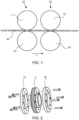
- Fig. 1 is a schematic illustration of a set-up 20 for pre-forming a metal strip 40.
- the set-up includes an embossing station with an embossing roll 1 and an anvil 22, and an edge chamfering tool 30 comprising a pair of roll 31, 32.
- the strip 40 travels through the pre-forming tools in a travel direction T.
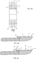
- Fig. 2 is an exploded perspective view of an example of an embossing roll
- Fig. 3a is a cross-sectional view of the same roll
- Figs. 3b show details.
- the embossing roll 1 has a cylindrical surface 2, which comprises a central portion 3 having an embossing pattern 10 and side portions 4a, 4b arranged on each side of the central portion 3.
- the side portions 4a, 4b are free from embossing pattern as shown in Fig. 3b .
- the cylindrical surface of the embossing roll has a total width W1, and the central portion has a width W2, which is 85-99% of the total width W1.
- the central portion 3 of the embossing roll 1 is comprised of a central embossing pattern roll 6, and the side portions 4a,4b are comprised of side rolls 7a,7b.
- the side rolls are arranged on each side of the central embossing roll.
- the embossing pattern 10 on the central portion of the embossing roll comprises a plurality of elongated grooves 11 having a depth D1 and being arranged at an angle with respect to the direction of rotation of the embossing roll, said groove depth D1 of the embossing pattern preferably being below 0.35 mm.
- the cylindrical surfaces of the side portions 4a,4b are level with the cylindrical surface of the central portion 3 between the grooves.
- Fig. 3c is a schematic cross-sectional view of a detail of a combined embossing and edge chamfering roll.
- the embossing portion 3' is arranged in the central section 34' of the recess 37'.
- the non-patterned side portion 4a' is also included in the central section 34'.
- the side section 35' includes the inclined edge chamfering side edges 36'.
- the central embossing roll can be in the form of an embossing pattern roll pack, comprising multiple embossing pattern rolls.
- the central portion 3 of the embossing roll 1 can be comprised of an embossing pattern roll pack including one or more embossing pattern discs 13a, 13b with cylindrical embossing surfaces having the same or different embossing pattern provided thereon.
- Fig. 4 illustrates a detail of an embossing roll pack comprising two pattern rolls, the metal strip 40 to be embossed, and the anvil 22.
- the embossing pattern roll pack comprises two embossing pattern discs 13a, 13b each having an embossing pattern consisting of grooves arranged at an angle, but with mirroring patterns, which together form a herringbone pattern on the embossed strip.
- Fig. 5 illustrates a detail of an embossing roll pack comprising a smooth spacer ring 15 between the embossing pattern disc 13a,13b.
- the cylindrical surface of each spacer ring is level with the cylindrical surface of the central portion 3 between the grooves.
- the embossing pattern discs 13a,13b and the smooth spacer ring 15 have bevelled edges 16,17 at the interface between them.
- Fig. 6 shows a partly cross-sectional view of a tube 18 having an interior embossed herringbone pattern 19.
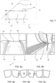
- Fig. 7 shows a cross-section of a portion of a finished pre-formed strip, which has been pre-formed by an embossing roll according to the present disclosure in a step subsequent to embossing.
- the contour of the recess provided in the edge chamfering roll 31 is indicated by means of a dashed line.
- the recess that comprises the central section 34 and the side sections 35 (of which only one is shown in Fig. 7 ) forms the strip receiving clearance 33 together with the anvil (not shown).
- the clearance 33 is dimensioned so that the fins 44 of embossed pattern in the central portion 41 of the strip are not affected, and in this example the side section 35 which comprises the outwardly inclined edge chamfering side edge 36 has a width which is greater than the non-patterned side portion 42 of the strip.
- the outermost edge of the strip is chamfered down to a thickness represented at the dashed line 43.
- the drawing also shows how the surface of the side portion 42 is level with the bottom of the grooves created between the fins 44 of the central portion 41 on which an embossing pattern is provided comprises a plurality of protruding fins 44 (only one fin is shown in this drawing).
- the fins 44 correspond to the grooves 11 of the embossing pattern 10 on the embossing roll ( Fig. 3b ).
- Fig. 8a shows a portion of an edge chamfering roll 31 comprising a central section 34 dimensioned such that an embossed pattern of a metal strip passing between the pair of rolls is not affected by the rolls 31,32.
- Side sections 35 are arranged on each side of the central section, in which the clearance 33 has a reduced height.
- the central section 34 and the side sections 35 together form a recess 37 running along the circumference of the cylindrical surface of the first roll.
- the recess has outwardly inclined side edges 36 on each side formed at the side sections 35.
- Fig. 8b shows a portion of an edge chamfering tool configured to receive and pass the metal strip 40 in a clearance 33 formed between the rolls 31, 32.
- the upper roll 31 corresponds to the roll shown in Fig. 8a .
- the upper roll forms the edge chamfering on the side of the strip which is to be the inside of the finished tube.
- the roll 32 acts as an anvil.
- Fig. 9a-c illustrates the welding principle and shows the seam section of a roll formed strip during welding of the longitudinal side edges thereof.
- the strip is roll formed until the chamfered edges have been brought close to one another ( Fig. 9a ).
- the nearly closed tube is subjected to high frequency welding by passing it through a welding coil, in which the strip material starts to melt due to the energy induced by the high frequency coil ( Fig. 9b ).
- the molten material fills the space formed between the chamfered edges of the strip and forms the weld bead ( Fig. 9c ). Because of this space and the low thickness of the strip at the welding area, the inner weld bead height can be kept at a minimum.
Landscapes
- Engineering & Computer Science (AREA)
- Mechanical Engineering (AREA)
- Shaping Metal By Deep-Drawing, Or The Like (AREA)
- Forging (AREA)
Description
- The present disclosure relates to an apparatus for pre-forming a metal strip for the manufacture of roll formed and welded tubes and a method of pre-forming a metal strip.
- Welded pipes and tubes are typically manufactured by longitudinally forming flat metal strips into a nearly complete tube and then welding the two edges together. There are many areas of application for roll formed tubing, for example in the field of the HVAC&R market (Heating, Ventilation, Air Conditioning, and Refrigeration). Within this technical field, environmental demands motivate a development toward air conditioning and refrigeration appliances with increased efficiency. In response to this, efforts have been made to supply smaller-diameter tubes with a wide range of inner surface enhancements, able to increase their heat transfer coefficient, in respect to standard smooth solutions. Methods of manufacture of advanced products such as small diameter welded tubes with inner surface patterning for heat exchange applications must result in products with minimal unwanted internal irregularities to obtain optimal flow properties and heat transfer. With increasing demands on cost reduction, there has been an interest in providing an alternative to copper tubing, which has traditionally been dominating for use in air conditioning and refrigeration appliances, in the form of aluminium tubing. It is therefore desirable to find a way to manufacture aluminium tubes with characteristics that are competitive for the purpose of applications such as within the field of HVAC&R.
-
WO 2019/168260 A1 discloses an engraved and embossed embossing mold roller having an interlocking structure, wherein, in order to solve a problem in that when an embossed pipe is manufactured using a pipe making machine for manufacturing a metal pipe, corrugated embossing patterns formed on an embossed metal plate may be deformed in the process of passing through a curved-male-and-female-interlocking-horizontal-roller and a circularization-interlocking-horizontal-and-vertical-roller of the pipe making machine, as a result of which the welding is impossible due to the inconsistency in the corrugated embossing patterns, a plane having a small width is formed in the lengthwise direction at each of both side edges of the embossed metal plate to be lower than the embossing pattern layer, so that a joint in the lengthwise direction of the embossed metal pipe can be welded, and a groove is formed in the welded joint, whereby an embossed metal plate which prevents a weld scar from being formed can be manufactured. -
JP 2000 346580 A -
WO 01/02124 A1 -
JP 2001 259733 A -
JP S60 196241 A - The present disclosure relates to an apparatus for pre-forming a metal strip for the manufacture of roll formed and welded tubes, according to claim 1.
- Preferably, the central section of the strip edge chamfering tool is dimensioned such that an embossed pattern of a metal strip passing between the pair of rolls through the edge chamfering clearance is not affected by the rolls. The strip edge chamfering tool (30) is thereby separate from the embossing tool and arranged downstream of the embossing tool in a travel direction (T) of the strip to be pre-formed.
- The first and second rolls are shaped such that the clearance comprises a central section dimensioned such that an embossed pattern of a metal strip passing between the pair of rolls is not affected by the rolls. The clearance further comprises side sections arranged on each side of the central section, in which the clearance has a reduced height. The side sections are located in a position where the longitudinal side edges of the metal strip will pass, so that the longitudinal side edges on each side of the metal strip, on the side of the metal strip directed toward the embossing roll, become chamfered when being passed between the pair of rolls. Thereby, the height of the weld bead of the finished roll formed and welded tube can be minimized.
- Alternatively, the embossing tool and the strip edge chamfering tool may be integrated so as to comprise one combined embossing and edge chamfering roll, whereby the central embossing portion is comprised in the central section of the edge chamfering clearance.
- The embossing roll can be comprised of a central embossing pattern roll pack and side rolls, where the side rolls are arranged on each side of the central embossing pattern roll pack, and wherein the central embossing pattern roll pack has a cylindrical surface forming the central portion and the side rolls have cylindrical surfaces forming the side portions. This allows flexibility as to the choice of embossing pattern. The cylindrical surface of the embossing roll preferably has a total width of 15 mm or more, and the central portion of the embossing roll suitable has a width which is 85-99% of the total width.
- The central section of the clearance between the first and second rolls of the strip edge chamfering tool, has a width which is equal to or greater than the width of the central portion of the embossing roll to ensure that the embossed pattern on the central portion of the strip is not affected by the passage through the edge chamfering tool. The first roll of the pair of rolls in the edge chamfering tool is preferably designed to comprise a recess having outwardly inclined side edges on each side of the recess, running along the circumference of the cylindrical surface of the first roll. The inclined side edges are suitably inclined at an angle of 30-60°, preferably 43-47°, to give a sufficient edge chamfering.
- The side sections of the clearance between the first and second rolls each may suitably have a width which for each of the side sections is equal to or greater than half of the difference between the total width of embossing tool (W1) and the width of the central portion of embossing tool (W2).
- The present disclosure further relates to a method of pre-forming a metal strip comprising embossing a pattern on the strip in a central portion in a longitudinal direction thereof, while side portions on each side of the central portion of the strip are rolled without embossing pattern, and chamfering the longitudinal side edges of the strip on the side of the strip which is provided with the embossed pattern. During the chamfering, the strip material at the longitudinal side edges of the strip are pressed down, up to 20-60 % of the strip thickness, preferably 35-40 %, thereby forming an inclined edge surface along the longitudinal side edges of the strip, in order to minimize the inner weld bead of the finished welded tube. The embossing pattern provided on the strip comprises protrusions, and the side portions of the strip are suitably rolled during the embossing step to a strip thickness which is approximately level with the strip thickness between the protrusions of the embossing pattern. Thereby, the side portions of the strip will have a lower thickness in respect to the thickness of original metal strip, which leads to a smaller inner weld bead in the tube. Chamfering of the side edges preferably follows in a subsequent step.
- The present disclosure will become apparent from the detailed description given below. The detailed description and specific examples disclose preferred embodiments of the disclosure by way of illustration only. Those skilled in the art understand from guidance in the detailed description that changes and modifications may be made within the scope of the appended claims.
-
-
Fig. 1 is a schematic illustration of a preferred pre-forming set-up; -
Fig. 2 is an exploded perspective view of an example of an embossing roll according to a preferred embodiment of the present disclosure; -
Fig. 3a is a cross-sectional view of the embossing roll ofFig. 2 ; -
Fig. 3b is a cross-sectional view of the encircled detail shown inFig. 3a ; -
Fig. 3c is a cross-sectional view of a detail of an alternative embodiment; -
Fig. 4 schematically illustrates a detail of an embossing portion of an embossing roll of an example according to the present disclosure; -
Fig. 5 schematically illustrates a detail of an embossing portion of an embossing roll of another example according to the present disclosure; -
Fig. 6 shows a partly cross-sectional view of a tube having an interior embossed pattern; -
Fig. 7 schematically illustrates the edge of a strip which is pre-formed by an embossing roll according to the present disclosure. -
Fig. 8a shows a portion of an edge chamfering roll; -
Fig. 8b shows a portion of an edge chamfering tool with a strip entering the tool; -
Fig. 9a-c shows schematically the seam section of a roll formed strip during welding of the longitudinal side edges thereof. - The present disclosure relates to an apparatus for pre-forming a metal strip for the manufacture of roll formed and welded tubes, comprising an embossing tool and a strip edge chamfering tool. The strip edge chamfering tool may preferably be arranged downstream of the embossing tool in a travel direction of the strip to be pre-formed. However, as an alternative, chamfering of the strip edges prior to the embossing may be contemplated, or integrating the embossing and the edge chamfering operation in one tool comprising a single combined embossing an edge chamfering roll and an anvil. In an apparatus with the edge chamfering tool arranged prior to the embossing tool in the strip travel direction, the embossing roll and the edge chamfering roll may include the same features and configuration as is described below for the embodiment in which the edge chamfering tool arranged subsequent to the embossing tool in the strip travel direction. In an apparatus comprising a combined embossing and edge chamfering tool with a single combined embossing an edge chamfering roll, the embossing and edge chamfering are performed simultaneously, which means that the embossing pattern is arranged within the recess of the strip receiving clearance, which is dimensioned so that the central portion of the strip receives the embossing pattern on its surface and the longitudinal side edges become chamfered, and that preferably a non-patterned portion is provided on each side of the embossed central portion of the strip.
- Regardless of how the strip pre-forming apparatus is set up, the intended result is the production of a pre-formed metal strip having an embossed surface pattern on a central portion thereof, and chamfered longitudinal side edge portions, which allows for efficient manufacture of small diameter tubes by roll forming and welding the pre-formed strip. In the following, the apparatus is described basically based on the preferred embodiment in which the embossing tool and the edge chamfering tool are separate tools, which each comprises a strip pre-forming roll and an anvil. However, it should be understood that the details described below apply to all these embodiments, unless otherwise indicated.
- By performing the embossing and the edge chamfering in separate subsequent steps, the strip pre-forming process is more flexible and the properties of the resulting pre-formed strip are easier to control. In this embodiment, the embossing tool comprises an embossing roll having a cylindrical surface with a central portion and side portions arranged on each side of the central portion, the central portion being provided with an embossing pattern and the side portions are free from embossing pattern. The strip edge chamfering tool comprises a pair of first and second rolls, wherein the first roll is an edge chamfering roll comprising a recessed central section and side sections on each side of the central section, and the second roll is an anvil roll. The edge chamfering roll and the anvil are configured to receive and pass the metal strip in a clearance formed between the rolls. The first and second rolls are shaped such that the clearance comprises a central section dimensioned such that an embossed pattern of a metal strip passing between the pair of rolls is not affected by the rolls. The clearance further comprises side sections arranged on each side of the central section, in which the clearance has a reduced height. The side sections are located in a position where the longitudinal side edges of the metal strip will pass, so that the longitudinal side edges on each side of the metal strip, on the side of the metal strip which was directed toward the embossing roll, become chamfered when being passed between the pair of rolls. Thereby, the height of the weld bead of the finished roll formed and welded tube can be minimized, as will be described in more detail below. Accordingly, by means for the apparatus a metal strip can be pre-formed so as to facilitate welding and result in a final tube product with improved weld quality.
- The final tube products may suitably be advanced small diameter tube products made of aluminium or alloys thereof, having a diameter of 20 mm or less, preferably 5-10 mm. The tube products are preferably manufactured as continuous tube coils having a length of over 500 m, preferably over 1000 m. Such tube products find use for example within the field of heating, ventilation, air conditioning or refrigeration.
- The process of welded tube roll forming involves roll forming a pre-formed strip into a tubular shape and welding the longitudinal edges of the strip together so as to obtain the tube by means of high frequency welding in an induction heating weld coil. To achieve this, the strip is fed into a forming mill or apparatus that shapes the strip through different consecutive forming steps, performed by as many forming rolls. As the strip passes through the weld coil, an electromagnetic field is induced around the weld coil, which induces a current to flow in the strip, mostly concentrated at the edges to be joined. The metals resistance to the electricity flow generates the necessary heat development at these edges, that rapidly reach the melting point. When the edges are still in molten state, they are forged together thanks to the interaction with side squeeze rolls, applying force on the strips and, therefore, generating the required pressure at the two edges' interface. When passing through the weld rolls, the oxidized metal and the molten metal are extruded out of the joint and the clean underlying metal is bonded. Following the welding, sizing rolls complete the process, giving desired final geometry to the tube.
- Production of advanced tube products such as small diameter welded tubes with inner surface patterning for heat exchange applications from metal strips involves a two-stage process, including the stage of pre-forming the strip, and the stage of roll forming the strip into a tubular shape and welding it into a tube.
- In the manufacture of roll formed and welded tube made from aluminium strips, it is important to mitigate problems that may arise due to characteristics of the aluminium material. In order to achieve desired heat transfer properties, the tubes have an interior embossed surface pattern. The variance in strip width should preferably be kept at a minimum to improve stability in the welding process and quality of the finished tube product.
- The strip is typically provided in the form of a blank strip coil to the pre-forming stage, in which the strip is prepared to be ready for tube forming and welding in the next stage. The pre-forming stage involves the step of embossing the strip on the surface that will form the inside of the tube, to obtain the embossed pattern that will form the inner grooves of the tube. After the pre-forming stage, the strip can suitably be stored in the form of a coil, until it is to be roll formed and welded in the form of a tube.
- The embossing procedure that is performed in an embossing station comprises a cold deformation process performed on strips with the aim of obtaining the surface pattern. The embossing pattern on the central portion of the embossing roll preferably comprises a plurality of elongated grooves having a certain depth and being arranged at an angle with respect to the direction of rotation of the embossing roll. The groove depth of the embossing roll pattern is preferably below 0.35 mm. Various embossing patterns can be applied, for example a helical pattern improves the performance in evaporation applications, and a herringbone pattern improves the performance in condensation applications.
- Applying the desired pattern onto the strip surface by embossing is a cold roll-forming process, where the blank strip is fed into a system of coupled rolls, comprising an embossing roll and an anvil roll, applying the necessary forming pressure. The embossing roll has a cylindrical surface comprising a central portion having an embossing pattern and side portions arranged on each side of the central portion. The side portions are free from embossing pattern. The central portion of the embossing roll is provided with a negative of the desired strip pattern, and is pressed onto the strip, which is sustained by the anvil roll, thereby cold roll-forming and embossing the strip. The embossing pattern provided on the embossing roll causes impression of a corresponding embossed pattern on the strip surface, where the grooves of the embossing roll pattern correspond to protruding fins on the strip, so that a pattern of fins is created on the strip surface. The fin height corresponds to maximum the groove depth of the embossing roll pattern.
- The anvil roll may be fixed in horizontal position, while the embossing roll may have the freedom to be adjusted in vertical direction, varying the gap between the rolls, thus allowing to tailor and optimally distribute forming pressure on the strip.
- The central portion of the embossing roll may be comprised of a central embossing pattern roll pack, and the side portions may be comprised of side rolls, arranged on each side of the central embossing roll pack. The central embossing pattern roll pack has a cylindrical surface forming the central portion of the embossing roll and the side rolls have cylindrical surfaces forming the side portions of the embossing roll. In this way flexibility as to the embossing pattern is obtained. Alternatively, the embossing roll can be made in one piece.
- The central embossing pattern roll pack can be comprised of a single embossing pattern disc, or two or more embossing pattern discs with or without spacer discs in between. The embossing pattern discs and the optionally included smooth spacer rings, may preferably have bevelled edges at the interface between them, so that circumferential channels are formed at said interfaces by the bevelled edges. This minimises locally stress in the material, and thus decreases the risk that the tool breaks.
- The central embossing pattern roll pack takes care of the pattern formation, and the side rolls serve to provide non-patterned side portions on the strip, described below, by pressing on the outer side portions of the strip. The two side rolls can be bolted to the central embossing ring, which can be clamped to a central shaft and fixed in position in the embossing station.
- As mentioned, the side portions of the embossing roll are free from embossing pattern. Thereby, the outer side portions along the cold roll-formed and embossed strip do not present any embossed pattern, but have a smooth surface. By providing these non-patterned side portions along the length of the strip during the pre-forming stage, the risk of variations in the strip edge thickness can be minimized and risk of uneven geometries at the strip edge being presented at welding point can be reduced, and the risk of embossed fins being welded together causing formation of a large inner weld bead can be avoided. Accordingly, the provision of the non-patterned side portions on the embossed strip allows for optimal control of the strip edge geometry, which is essential in ensuring optimal welding conditions, to improve process stability and post-welding tube quality.
- The cylindrical surface of the embossing roll may suitably have a total width of 15 mm or more, and the central portion has a width, which is 85-99 % of the total width. A strip width of 15 mm or more is suitable for the manufacture of heat exchanger tubes for HVAC&R applications, for example up to 64 mm.
- The width of the non-patterned side portions of the embossing roll is determined based on considerations related to the welding ease and the heat transfer performances of finished tube. Wider non-patterned side portions will be easier to weld, since this will be closer to a standard procedure of smooth strip welding. However, too wide non-patterned side portions may adversely affect the final heat transfer performances, since in the ideal case a continuous pattern all around the inner circumference of the tube would be desired. Accordingly, the width of the non-patterned side portions should preferably be a small as possible, while still ensuring that no embossed fin would have been included in the inner weld bead. It has been found that the combined width of both non-patterned strip side portions should preferably be 1-15 % of the total strip width when the strip has a total width of 15 mm or more.
- The cylindrical surfaces of the side portions of the embossing roll are preferably level with the cylindrical surface of the central portion between the grooves of the embossing roll pattern. This is particularly beneficial in combination with the edge chamfering of the strip that takes place in the subsequent step of the pre-forming, described below, since it can further reduce the height of the inner weld bead of the finished welded tube. Accordingly, the strip in the area of the non-patterned side portions is preferably rolled down to nominal bottom wall thickness of the strip during the embossing stages, i.e. so as to be level with the bottom of the grooves between the fins of the embossed surface pattern. Therefore, the side portions are kept smooth but are still rolled to a thickness lower than the original one in blank form. This improves the performance of the final tube, since the inner weld bead height can be reduced, resulting in less disturbance to fluid dynamics within the final tube. The desired thickness of the non-patterned side portions can be obtained by selecting the outer diameter of the embossing roll at the side portions to be the same as the outer diameter of the embossing roll at the central portion.
- During high frequency welding of roll formed tubes in an induction heating weld coil, a weld bead is normally formed on the inside of the tube. The high frequency welding process is a true hot forging process, during which a molten part of the tube edges is ejected out of the welding area both inside and outside the tube. The inner ejection forms, after solidification, the inner bead. For larger diameter tubes, the weld bead does rarely present a problem. However, internally enhanced tubes suitable for HVAC&R applications typically have a small diameter suitably 20 mm or less, and it is therefore important that the inner weld bead is as small as possible. To ensure minimum inner bead height, while maintaining tube burst pressure at required levels, the strip edges of the incoming embossed strip are modified in shape. The strip edges are chamfered on the side that will form the inside of the tube, in a cold roll forming process. By tailoring the chamfering angle and the length defining the slope and dimension of the chamfering, the height of the inner bead can be kept sufficiently low to be contained within the depth of the embossed surface pattern.
- As mentioned, according to the preferred embodiment, the strip edge chamfering tool comprises a pair of first and second rolls, which are configured to receive and pass the metal strip in a clearance formed between the rolls. The first and second rolls are shaped such that the clearance comprises a central section dimensioned such that an embossed pattern of a metal strip passing between the pair of rolls is not affected by the rolls. This ensures that the embossed pattern is kept intact on a strip that has been embossed prior to entering the edge chamfering tool. The clearance further comprises side sections arranged on each side of the central section, in which the clearance has a reduced height. The side sections are located in a position where the longitudinal side edges of the metal strip will pass, so that the longitudinal side edges on each side of the metal strip, on the side of the metal strip which was directed toward the embossing roll, become chamfered when being passed between the pair of rolls. After roll forming of the strip into a nearly finished tube form, the edges of the strip will be welded together. Due to the edges chamfering, less material is present at the longitudinal edges of the strip. This is particularly pronounced when the non-patterned side portions of the strip have been rolled to be level with the bottom of the embossed pattern as described above. In this way, inner weld bead starts building up on the inner surface of the tube from a bottom wall thickness level, instead of the higher original strip thickness. Less material is ejected from the welding area and the chamfered edges form a space where a part of the molten material can be contained. Thereby, the height of the weld bead of the finished roll formed and welded tube can be minimized, while maintaining the capability of the finished products to meet the mechanical requirements.
- The rolls of the edge chamfering tool can be designed in various ways. Preferably, the first roll of the pair of rolls in the edge chamfering tool is arranged such that the embossed side of the strip will face the first roll, and is designed to comprise a recess having outwardly inclined side edges on each side of the recess, running along the circumference of the cylindrical surface of the first roll. The inclined side edges are suitably inclined at an angle of 30-60°, preferably 43-47°, to give a sufficient edge chamfering. The side sections of the clearance between the first and second rolls each may suitably have a width which for each of the side sections is equal to or greater than half of the difference between the total width of embossing tool (W1) and the width of the central portion of embossing tool (W2). As the clearance between the rolls of the edge chamfering tool is dimensioned so as to not affect the embossing pattern, by having a height that exceeds the maximum strip thickness, an outer edge of the strip is chamfered by the inclined sides of chamfer roll side sections, as schematically illustrated in
Fig. 7 , which shows an edge chamfering operation in a step subsequent to the embossing step. - The present disclosure further relates to a method of pre-forming a metal strip comprising embossing a pattern on the strip in a central portion in a longitudinal direction thereof, while side portions on each side of the central portion of the strip are rolled without embossing pattern, and chamfering the longitudinal side edges of the strip on the side of the strip which is provided with the embossed pattern. As mentioned above, the embossing is preferably performed separately prior to edge chamfering, but can if desired be performed subsequent to, or simultaneously with, the edge chamfering. During the chamfering, the strip material at the longitudinal side edges of the strip are pressed down, up to 20-60 % of the strip thickness, preferably 35-40 %, thereby forming an inclined edge surface along the longitudinal side edges of the strip, in order to minimize the inner weld bead of the finished welded tube. The embossing pattern provided on the strip comprises protrusions, and the side portions of the strip are suitably rolled during the embossing step to a strip thickness which is approximately level with the strip thickness between the protrusions of the embossing pattern, which is particularly advantageous when the embossing is performed prior to edge chamfering.. Thereby, the side portions of the strip will have a lower thickness which lead to a smaller inner weld bead in the tube.
- The present disclosure will now be described with reference to the accompanying drawings, in which preferred example embodiments of the disclosure are shown. The disclosure may, however, be embodied in other forms and should not be construed as limited to the herein disclosed embodiments. The disclosed embodiments are provided to fully convey the scope of the disclosure to the skilled person.
-
Fig. 1 is a schematic illustration of a set-up 20 for pre-forming ametal strip 40. The set-up includes an embossing station with an embossing roll 1 and ananvil 22, and anedge chamfering tool 30 comprising a pair ofroll strip 40 travels through the pre-forming tools in a travel direction T. -
Fig. 2 is an exploded perspective view of an example of an embossing roll, andFig. 3a is a cross-sectional view of the same roll, andFigs. 3b show details. The embossing roll 1 has acylindrical surface 2, which comprises acentral portion 3 having anembossing pattern 10 andside portions central portion 3. Theside portions Fig. 3b . The cylindrical surface of the embossing roll has a total width W1, and the central portion has a width W2, which is 85-99% of the total width W1. - In the shown example, the
central portion 3 of the embossing roll 1 is comprised of a centralembossing pattern roll 6, and theside portions embossing pattern 10 on the central portion of the embossing roll comprises a plurality of elongated grooves 11 having a depth D1 and being arranged at an angle with respect to the direction of rotation of the embossing roll, said groove depth D1 of the embossing pattern preferably being below 0.35 mm. As shown inFigs. 3a-b , the cylindrical surfaces of theside portions central portion 3 between the grooves. -
Fig. 3c is a schematic cross-sectional view of a detail of a combined embossing and edge chamfering roll. In this case, the embossing portion 3' is arranged in the central section 34' of the recess 37'. Thenon-patterned side portion 4a' is also included in the central section 34'. The side section 35' includes the inclined edge chamfering side edges 36'. - The central embossing roll can be in the form of an embossing pattern roll pack, comprising multiple embossing pattern rolls. Thus, the
central portion 3 of the embossing roll 1 can be comprised of an embossing pattern roll pack including one or moreembossing pattern discs Fig. 4 illustrates a detail of an embossing roll pack comprising two pattern rolls, themetal strip 40 to be embossed, and theanvil 22. In this case, the embossing pattern roll pack comprises twoembossing pattern discs Fig. 5 illustrates a detail of an embossing roll pack comprising asmooth spacer ring 15 between theembossing pattern disc central portion 3 between the grooves. As shown inFig. 5 , theembossing pattern discs smooth spacer ring 15 have bevellededges Fig. 6 shows a partly cross-sectional view of atube 18 having an interior embossedherringbone pattern 19. -
Fig. 7 shows a cross-section of a portion of a finished pre-formed strip, which has been pre-formed by an embossing roll according to the present disclosure in a step subsequent to embossing. The contour of the recess provided in theedge chamfering roll 31 is indicated by means of a dashed line. The recess that comprises thecentral section 34 and the side sections 35 (of which only one is shown inFig. 7 ) forms thestrip receiving clearance 33 together with the anvil (not shown). Theclearance 33 is dimensioned so that thefins 44 of embossed pattern in thecentral portion 41 of the strip are not affected, and in this example theside section 35 which comprises the outwardly inclined edge chamferingside edge 36 has a width which is greater than thenon-patterned side portion 42 of the strip. The outermost edge of the strip is chamfered down to a thickness represented at the dashedline 43. The drawing also shows how the surface of theside portion 42 is level with the bottom of the grooves created between thefins 44 of thecentral portion 41 on which an embossing pattern is provided comprises a plurality of protruding fins 44 (only one fin is shown in this drawing). Thefins 44 correspond to the grooves 11 of theembossing pattern 10 on the embossing roll (Fig. 3b ). -
Fig. 8a shows a portion of anedge chamfering roll 31 comprising acentral section 34 dimensioned such that an embossed pattern of a metal strip passing between the pair of rolls is not affected by therolls Side sections 35 are arranged on each side of the central section, in which theclearance 33 has a reduced height. Thecentral section 34 and theside sections 35 together form arecess 37 running along the circumference of the cylindrical surface of the first roll. The recess has outwardly inclined side edges 36 on each side formed at theside sections 35.Fig. 8b shows a portion of an edge chamfering tool configured to receive and pass themetal strip 40 in aclearance 33 formed between therolls upper roll 31 corresponds to the roll shown inFig. 8a . the upper roll forms the edge chamfering on the side of the strip which is to be the inside of the finished tube. Theroll 32 acts as an anvil. -
Fig. 9a-c illustrates the welding principle and shows the seam section of a roll formed strip during welding of the longitudinal side edges thereof. After pre-forming in the apparatus comprising the embossing tool and the edge chamfering tool, the strip is roll formed until the chamfered edges have been brought close to one another (Fig. 9a ). The nearly closed tube is subjected to high frequency welding by passing it through a welding coil, in which the strip material starts to melt due to the energy induced by the high frequency coil (Fig. 9b ). During the welding, the molten material fills the space formed between the chamfered edges of the strip and forms the weld bead (Fig. 9c ). because of this space and the low thickness of the strip at the welding area, the inner weld bead height can be kept at a minimum. - The person skilled in the art realizes that the present disclosure is not limited to the preferred embodiments described above. The person skilled in the art further realizes that modifications and variations are possible within the scope of the appended claims. Additionally, variations to the disclosed embodiments can be understood and effected by the skilled person in practicing the claimed disclosure, from a study of the drawings, the disclosure, and the appended claims.
Claims (13)
- An apparatus for pre-forming a metal strip (40) for the manufacture of roll formed and high frequency welded tubes with inner grooves, comprising an embossing tool (20) and a strip edge chamfering tool (30) wherein- the embossing tool comprises an embossing roll (1) having a cylindrical surface (2) with a central embossing portion (3, 3'), and side portions (4a, 4b) arranged on each side of the central embossing portion, said central portion being provided with an embossing pattern (10) and said side portions being free from embossing pattern,
characterized in that- the strip edge chamfering tool comprises an edge chamfering roll (31) comprising a recessed central section (34, 34') and side sections (35, 35') on each side of the central section, and an anvil roll (32), wherein the edge chamfering roll (31) and the anvil roll (32) are configured to receive and pass, in use, the metal strip in a clearance (33) formed between the rolls, wherein the clearance (33) has a reduced height in the side sections, which are located in a position where the longitudinal side edges of the metal strip will pass, so that the longitudinal side edges on each side of the metal strip, and on the embossed side of the metal strip become chamfered when being passed between the pair of rolls (31, 32),wherein an embossing pattern (10) on the central embossing portion comprises a plurality of grooves (11) arranged in the cylindrical surface of the central portion (3), andwherein the cylindrical surface of each side portion (4a, 4b) is level with the cylindrical surface of the central portion (3) between the grooves. - The apparatus of claim 1, wherein- the strip edge chamfering tool (30) is arranged downstream of the embossing tool in a travel direction (T) of the strip to be pre-formed, and- the central section (34) of the strip edge chamfering tool (30) is dimensioned such that an embossed pattern of a metal strip passing between the pair of rolls through the edge chamfering clearance (33) is not affected by the rolls (31, 32).
- The apparatus of claim 1, wherein the embossing tool and the strip edge chamfering tool are integrated so as to comprise one combined embossing and edge chamfering roll, whereby the central embossing portion (3') is comprised in the central section (34') of the edge chamfering clearance (33).
- The apparatus of any one of claims 1-3, wherein the embossing roll (1) is comprised of a central embossing pattern roll pack (6) and side rolls (7a, 7b), said side rolls being arranged on each side of the central embossing pattern roll pack, and wherein the central embossing pattern roll pack has a cylindrical surface forming the central portion (3) and the side rolls have cylindrical surfaces forming the side portions (4a, 4b).
- The apparatus of any one of claims 1-4, wherein the cylindrical surface of the embossing roll has a total width (W1) of 15 mm or more, and the central portion of the embossing roll has a width (W2), which is 85-99% of the total width (W1).
- The apparatus of claim 5, wherein the central section (34) of the clearance (33) between the first and second rolls (31, 32) of the strip edge chamfering tool (30), has a width (W3) which is equal to or greater than the width (W2) of the central portion (3) of the embossing roll (1).
- The apparatus of claim 5 or 6, wherein the side sections (35) of the clearance (33) between the first and second rolls (31, 32) each have a width which is equal to or greater than half of the difference between the total width of embossing tool (W1) and the width of the central portion of embossing tool (W2).
- The apparatus of any one of claims 1-7, wherein the first roll (31) of the pair of rolls in the edge chamfering tool comprises a recess (37) having outwardly inclined side edges (36) on each side of the recess, running along the circumference of the cylindrical surface of the first roll.
- The apparatus of claim 8, wherein the inclined side edges (36) are inclined at an angle of 30-60°, preferably 43-47°.
- A method of pre-forming a metal strip (40) for the manufacture of roll formed and high frequency welded tubes with inner grooves, using the apparatus of any one of the preceding claims, and comprising the steps of:- embossing a pattern on a central portion (41) of the strip, in a longitudinal direction thereof, while side portions (42) on each side of the central portion of the strip are rolled without embossing pattern, wherein the embossing pattern comprises protrusions (44), and the side portions of the strip are rolled during the embossing step to a strip thickness which is approximately level with the strip thickness between the protrusions of the embossing pattern, and- chamfering the longitudinal side edges (43) of the strip on the side of the strip which is provided with the embossed pattern.
- The method of claim 10, wherein, during the chamfering, the strip material at the longitudinal side edges (43) of the strip are pressed down, up to 20-60 % of the strip thickness, preferably 35-40 %, thereby forming an inclined edge surface along the longitudinal side edges of the strip.
- The method of claim 10 or 11 using the apparatus of any one of claims 2 or 4 to 9 when depending on claim 2, wherein chamfering of the side edges follows in a subsequent step.
- The method of claim 10 or 11 using the apparatus of any one of claims 3 or 4 to 9 when dependent on claim 3, wherein the embossing and edge chamfering are performed simultaneously in an integrated embossing and edge chamfering tool.
Applications Claiming Priority (2)
| Application Number | Priority Date | Filing Date | Title |
|---|---|---|---|
| SE2050714 | 2020-06-15 | ||
| PCT/EP2021/065683 WO2021254884A2 (en) | 2020-06-15 | 2021-06-10 | Apparatus and method for pre-forming a metal strip for the manufacture of roll formed and welded tubes |
Publications (2)
| Publication Number | Publication Date |
|---|---|
| EP4164817A2 EP4164817A2 (en) | 2023-04-19 |
| EP4164817B1 true EP4164817B1 (en) | 2024-10-16 |
Family
ID=76522949
Family Applications (1)
| Application Number | Title | Priority Date | Filing Date |
|---|---|---|---|
| EP21733410.1A Active EP4164817B1 (en) | 2020-06-15 | 2021-06-10 | Apparatus and method for pre-forming a metal strip for the manufacture of roll formed and welded tubes |
Country Status (8)
| Country | Link |
|---|---|
| US (1) | US20230278085A1 (en) |
| EP (1) | EP4164817B1 (en) |
| JP (1) | JP7692440B2 (en) |
| KR (1) | KR20230025700A (en) |
| CN (1) | CN115884838B (en) |
| MX (1) | MX2022016043A (en) |
| PL (1) | PL4164817T3 (en) |
| WO (1) | WO2021254884A2 (en) |
Families Citing this family (1)
| Publication number | Priority date | Publication date | Assignee | Title |
|---|---|---|---|---|
| CN117753782B (en) * | 2024-02-21 | 2024-05-03 | 山西广华源药用包装有限公司 | Calendaring molding machine for aluminum foil processing |
Family Cites Families (14)
| Publication number | Priority date | Publication date | Assignee | Title |
|---|---|---|---|---|
| US133454A (en) * | 1872-11-26 | Improvement in rolls for metal-rolling mills | ||
| JPS60196241A (en) * | 1984-03-21 | 1985-10-04 | Nippon Steel Metal Prod Co Ltd | Working method of groove for welding lightweight shape steel |
| JPH0246975A (en) * | 1988-08-09 | 1990-02-16 | Sekisui Chem Co Ltd | Production of composite pipe |
| JP2577502B2 (en) * | 1990-10-16 | 1997-02-05 | 三菱伸銅株式会社 | Method of manufacturing inner grooved pipe |
| US6164370A (en) * | 1993-07-16 | 2000-12-26 | Olin Corporation | Enhanced heat exchange tube |
| DE19908784A1 (en) * | 1999-02-17 | 2000-08-24 | Sms Demag Ag | Internally ribbed, welded copper tube, e.g. heat exchanger tube, production comprises in-line embossing and longitudinal cutting of cold rolled strip before supply as coils to tube welding units |
| JP2000346580A (en) * | 1999-05-28 | 2000-12-15 | Mitsubishi Shindoh Co Ltd | Heat transfer tube with inner groove, method of manufacturing the same, and manufacturing apparatus |
| JP2001018059A (en) * | 1999-07-01 | 2001-01-23 | Mitsubishi Shindoh Co Ltd | Method and apparatus for manufacturing heat transfer tube with inner groove |
| JP2001259733A (en) * | 2000-03-16 | 2001-09-25 | Mitsubishi Shindoh Co Ltd | Apparatus and method for manufacturing ERW pipe |
| JP2002292411A (en) * | 2001-03-29 | 2002-10-08 | Kobe Steel Ltd | Cross groove forming apparatus, method of manufacturing cross grooved rolled strip using the same, method of manufacturing cross grooved welded pipe, cross grooved rolled strip and cross grooved welded pipe |
| DE102007004993A1 (en) * | 2007-02-01 | 2008-08-07 | Modine Manufacturing Co., Racine | Production process for flat tubes and roller mill |
| CN105642700A (en) * | 2016-03-28 | 2016-06-08 | 徐晓冰 | Method for manufacturing flat tubes |
| KR101884364B1 (en) * | 2018-02-28 | 2018-08-01 | 보 현 이 | Embossing roller having intaglio and relief with interlocking structure used in the manufacture of a embossing metal pipe |
| CN115666815A (en) * | 2020-06-15 | 2023-01-31 | 海德鲁挤压解决方案股份有限公司 | Embossing roller |
-
2021
- 2021-06-10 MX MX2022016043A patent/MX2022016043A/en unknown
- 2021-06-10 CN CN202180042012.9A patent/CN115884838B/en active Active
- 2021-06-10 WO PCT/EP2021/065683 patent/WO2021254884A2/en not_active Ceased
- 2021-06-10 EP EP21733410.1A patent/EP4164817B1/en active Active
- 2021-06-10 PL PL21733410.1T patent/PL4164817T3/en unknown
- 2021-06-10 JP JP2022576384A patent/JP7692440B2/en active Active
- 2021-06-10 US US18/010,302 patent/US20230278085A1/en active Pending
- 2021-06-10 KR KR1020237001674A patent/KR20230025700A/en active Pending
Also Published As
| Publication number | Publication date |
|---|---|
| JP7692440B2 (en) | 2025-06-13 |
| PL4164817T3 (en) | 2025-01-20 |
| US20230278085A1 (en) | 2023-09-07 |
| CN115884838B (en) | 2026-07-31 |
| CN115884838A (en) | 2023-03-31 |
| WO2021254884A2 (en) | 2021-12-23 |
| JP2023531170A (en) | 2023-07-21 |
| KR20230025700A (en) | 2023-02-22 |
| EP4164817A2 (en) | 2023-04-19 |
| WO2021254884A3 (en) | 2022-02-10 |
| MX2022016043A (en) | 2023-04-19 |
Similar Documents
| Publication | Publication Date | Title |
|---|---|---|
| US6375059B2 (en) | Method for smoothing steel pipe seam portion | |
| EP1312885B1 (en) | Heat exchange tube structured on both sides and process for making same | |
| US5730189A (en) | Internally and externally enhanced wielded tube | |
| EP0688625A1 (en) | Projection resistance welding method | |
| EP0998994A2 (en) | Multi-wall tube | |
| CA2640235A1 (en) | Method of manufacturing lined tubing | |
| JP3254432U (en) | Embossing Roll | |
| JP2001259733A (en) | Apparatus and method for manufacturing ERW pipe | |
| US20230278085A1 (en) | Apparatus and method for pre-forming a metal strip for the manufacture of roll formed and welded tubes | |
| EP0865938A1 (en) | Method of producing light alloy wheels | |
| US3453720A (en) | Method of making axles | |
| JP3052555B2 (en) | Manufacturing method of small-diameter ERW pipe | |
| US5215245A (en) | Method for roll embossing metal strip | |
| JP2004148337A (en) | Method for forming welded joint of welded steel pipe and apparatus for manufacturing the same | |
| KR100773339B1 (en) | Clad Tank for Air Conditioning Parts and Manufacturing Method Thereof | |
| EP0589104B1 (en) | Method of producing tubing | |
| JPH06104251B2 (en) | Welded steel pipe manufacturing equipment | |
| JP2004195504A (en) | Steel pipe forming device, forming method, and manufacturing equipment line | |
| JPH1052714A (en) | Heat transfer tube with inner groove and method of manufacturing the same | |
| JPS61159238A (en) | Method and apparatus for fabricating ring plate shaped constitutional member forming cylindrical gathered pipe structure of heat exchanger | |
| JP2000346580A (en) | Heat transfer tube with inner groove, method of manufacturing the same, and manufacturing apparatus | |
| JP3756936B2 (en) | Internal grooved welded heat transfer tube and its manufacturing method | |
| JPH0787942B2 (en) | Heat transfer tube manufacturing method | |
| JP3069277B2 (en) | Heat transfer tube with inner groove and method of manufacturing the same | |
| JPH02258113A (en) | Seamless steel pipe |
Legal Events
| Date | Code | Title | Description |
|---|---|---|---|
| STAA | Information on the status of an ep patent application or granted ep patent |
Free format text: STATUS: UNKNOWN |
|
| STAA | Information on the status of an ep patent application or granted ep patent |
Free format text: STATUS: THE INTERNATIONAL PUBLICATION HAS BEEN MADE |
|
| PUAI | Public reference made under article 153(3) epc to a published international application that has entered the european phase |
Free format text: ORIGINAL CODE: 0009012 |
|
| STAA | Information on the status of an ep patent application or granted ep patent |
Free format text: STATUS: REQUEST FOR EXAMINATION WAS MADE |
|
| 17P | Request for examination filed |
Effective date: 20230116 |
|
| AK | Designated contracting states |
Kind code of ref document: A2 Designated state(s): AL AT BE BG CH CY CZ DE DK EE ES FI FR GB GR HR HU IE IS IT LI LT LU LV MC MK MT NL NO PL PT RO RS SE SI SK SM TR |
|
| P01 | Opt-out of the competence of the unified patent court (upc) registered |
Effective date: 20230525 |
|
| DAV | Request for validation of the european patent (deleted) | ||
| DAX | Request for extension of the european patent (deleted) | ||
| STAA | Information on the status of an ep patent application or granted ep patent |
Free format text: STATUS: EXAMINATION IS IN PROGRESS |
|
| 17Q | First examination report despatched |
Effective date: 20240124 |
|
| GRAP | Despatch of communication of intention to grant a patent |
Free format text: ORIGINAL CODE: EPIDOSNIGR1 |
|
| STAA | Information on the status of an ep patent application or granted ep patent |
Free format text: STATUS: GRANT OF PATENT IS INTENDED |
|
| INTG | Intention to grant announced |
Effective date: 20240617 |
|
| GRAJ | Information related to disapproval of communication of intention to grant by the applicant or resumption of examination proceedings by the epo deleted |
Free format text: ORIGINAL CODE: EPIDOSDIGR1 |
|
| STAA | Information on the status of an ep patent application or granted ep patent |
Free format text: STATUS: EXAMINATION IS IN PROGRESS |
|
| GRAS | Grant fee paid |
Free format text: ORIGINAL CODE: EPIDOSNIGR3 |
|
| STAA | Information on the status of an ep patent application or granted ep patent |
Free format text: STATUS: GRANT OF PATENT IS INTENDED |
|
| GRAP | Despatch of communication of intention to grant a patent |
Free format text: ORIGINAL CODE: EPIDOSNIGR1 |
|
| GRAA | (expected) grant |
Free format text: ORIGINAL CODE: 0009210 |
|
| STAA | Information on the status of an ep patent application or granted ep patent |
Free format text: STATUS: THE PATENT HAS BEEN GRANTED |
|
| INTC | Intention to grant announced (deleted) | ||
| INTG | Intention to grant announced |
Effective date: 20240905 |
|
| AK | Designated contracting states |
Kind code of ref document: B1 Designated state(s): AL AT BE BG CH CY CZ DE DK EE ES FI FR GB GR HR HU IE IS IT LI LT LU LV MC MK MT NL NO PL PT RO RS SE SI SK SM TR |
|
| REG | Reference to a national code |
Ref country code: GB Ref legal event code: FG4D |
|
| REG | Reference to a national code |
Ref country code: DE Ref legal event code: R096 Ref document number: 602021020375 Country of ref document: DE Ref country code: CH Ref legal event code: EP |
|
| REG | Reference to a national code |
Ref country code: IE Ref legal event code: FG4D |
|
| REG | Reference to a national code |
Ref country code: LT Ref legal event code: MG9D |
|
| REG | Reference to a national code |
Ref country code: NL Ref legal event code: MP Effective date: 20241016 |
|
| REG | Reference to a national code |
Ref country code: AT Ref legal event code: MK05 Ref document number: 1732539 Country of ref document: AT Kind code of ref document: T Effective date: 20241016 |
|
| PG25 | Lapsed in a contracting state [announced via postgrant information from national office to epo] |
Ref country code: NL Free format text: LAPSE BECAUSE OF FAILURE TO SUBMIT A TRANSLATION OF THE DESCRIPTION OR TO PAY THE FEE WITHIN THE PRESCRIBED TIME-LIMIT Effective date: 20241016 |
|
| PG25 | Lapsed in a contracting state [announced via postgrant information from national office to epo] |
Ref country code: NL Free format text: LAPSE BECAUSE OF FAILURE TO SUBMIT A TRANSLATION OF THE DESCRIPTION OR TO PAY THE FEE WITHIN THE PRESCRIBED TIME-LIMIT Effective date: 20241016 |
|
| PG25 | Lapsed in a contracting state [announced via postgrant information from national office to epo] |
Ref country code: IS Free format text: LAPSE BECAUSE OF FAILURE TO SUBMIT A TRANSLATION OF THE DESCRIPTION OR TO PAY THE FEE WITHIN THE PRESCRIBED TIME-LIMIT Effective date: 20250216 Ref country code: HR Free format text: LAPSE BECAUSE OF FAILURE TO SUBMIT A TRANSLATION OF THE DESCRIPTION OR TO PAY THE FEE WITHIN THE PRESCRIBED TIME-LIMIT Effective date: 20241016 Ref country code: PT Free format text: LAPSE BECAUSE OF FAILURE TO SUBMIT A TRANSLATION OF THE DESCRIPTION OR TO PAY THE FEE WITHIN THE PRESCRIBED TIME-LIMIT Effective date: 20250217 |
|
| PG25 | Lapsed in a contracting state [announced via postgrant information from national office to epo] |
Ref country code: FI Free format text: LAPSE BECAUSE OF FAILURE TO SUBMIT A TRANSLATION OF THE DESCRIPTION OR TO PAY THE FEE WITHIN THE PRESCRIBED TIME-LIMIT Effective date: 20241016 |
|
| PG25 | Lapsed in a contracting state [announced via postgrant information from national office to epo] |
Ref country code: BG Free format text: LAPSE BECAUSE OF FAILURE TO SUBMIT A TRANSLATION OF THE DESCRIPTION OR TO PAY THE FEE WITHIN THE PRESCRIBED TIME-LIMIT Effective date: 20241016 |
|
| PG25 | Lapsed in a contracting state [announced via postgrant information from national office to epo] |
Ref country code: ES Free format text: LAPSE BECAUSE OF FAILURE TO SUBMIT A TRANSLATION OF THE DESCRIPTION OR TO PAY THE FEE WITHIN THE PRESCRIBED TIME-LIMIT Effective date: 20241016 |
|
| PG25 | Lapsed in a contracting state [announced via postgrant information from national office to epo] |
Ref country code: NO Free format text: LAPSE BECAUSE OF FAILURE TO SUBMIT A TRANSLATION OF THE DESCRIPTION OR TO PAY THE FEE WITHIN THE PRESCRIBED TIME-LIMIT Effective date: 20250116 |
|
| PG25 | Lapsed in a contracting state [announced via postgrant information from national office to epo] |
Ref country code: LV Free format text: LAPSE BECAUSE OF FAILURE TO SUBMIT A TRANSLATION OF THE DESCRIPTION OR TO PAY THE FEE WITHIN THE PRESCRIBED TIME-LIMIT Effective date: 20241016 Ref country code: AT Free format text: LAPSE BECAUSE OF FAILURE TO SUBMIT A TRANSLATION OF THE DESCRIPTION OR TO PAY THE FEE WITHIN THE PRESCRIBED TIME-LIMIT Effective date: 20241016 Ref country code: GR Free format text: LAPSE BECAUSE OF FAILURE TO SUBMIT A TRANSLATION OF THE DESCRIPTION OR TO PAY THE FEE WITHIN THE PRESCRIBED TIME-LIMIT Effective date: 20250117 |
|
| PG25 | Lapsed in a contracting state [announced via postgrant information from national office to epo] |
Ref country code: RS Free format text: LAPSE BECAUSE OF FAILURE TO SUBMIT A TRANSLATION OF THE DESCRIPTION OR TO PAY THE FEE WITHIN THE PRESCRIBED TIME-LIMIT Effective date: 20250116 |
|
| PG25 | Lapsed in a contracting state [announced via postgrant information from national office to epo] |
Ref country code: SM Free format text: LAPSE BECAUSE OF FAILURE TO SUBMIT A TRANSLATION OF THE DESCRIPTION OR TO PAY THE FEE WITHIN THE PRESCRIBED TIME-LIMIT Effective date: 20241016 |
|
| PG25 | Lapsed in a contracting state [announced via postgrant information from national office to epo] |
Ref country code: DK Free format text: LAPSE BECAUSE OF FAILURE TO SUBMIT A TRANSLATION OF THE DESCRIPTION OR TO PAY THE FEE WITHIN THE PRESCRIBED TIME-LIMIT Effective date: 20241016 |
|
| REG | Reference to a national code |
Ref country code: DE Ref legal event code: R097 Ref document number: 602021020375 Country of ref document: DE |
|
| PG25 | Lapsed in a contracting state [announced via postgrant information from national office to epo] |
Ref country code: EE Free format text: LAPSE BECAUSE OF FAILURE TO SUBMIT A TRANSLATION OF THE DESCRIPTION OR TO PAY THE FEE WITHIN THE PRESCRIBED TIME-LIMIT Effective date: 20241016 |
|
| PG25 | Lapsed in a contracting state [announced via postgrant information from national office to epo] |
Ref country code: RO Free format text: LAPSE BECAUSE OF FAILURE TO SUBMIT A TRANSLATION OF THE DESCRIPTION OR TO PAY THE FEE WITHIN THE PRESCRIBED TIME-LIMIT Effective date: 20241016 |
|
| PG25 | Lapsed in a contracting state [announced via postgrant information from national office to epo] |
Ref country code: SK Free format text: LAPSE BECAUSE OF FAILURE TO SUBMIT A TRANSLATION OF THE DESCRIPTION OR TO PAY THE FEE WITHIN THE PRESCRIBED TIME-LIMIT Effective date: 20241016 |
|
| PLBE | No opposition filed within time limit |
Free format text: ORIGINAL CODE: 0009261 |
|
| STAA | Information on the status of an ep patent application or granted ep patent |
Free format text: STATUS: NO OPPOSITION FILED WITHIN TIME LIMIT |
|
| PG25 | Lapsed in a contracting state [announced via postgrant information from national office to epo] |
Ref country code: SE Free format text: LAPSE BECAUSE OF FAILURE TO SUBMIT A TRANSLATION OF THE DESCRIPTION OR TO PAY THE FEE WITHIN THE PRESCRIBED TIME-LIMIT Effective date: 20241016 |
|
| 26N | No opposition filed |
Effective date: 20250717 |
|
| REG | Reference to a national code |
Ref country code: CH Ref legal event code: H13 Free format text: ST27 STATUS EVENT CODE: U-0-0-H10-H13 (AS PROVIDED BY THE NATIONAL OFFICE) Effective date: 20260127 |
|
| PG25 | Lapsed in a contracting state [announced via postgrant information from national office to epo] |
Ref country code: MC Free format text: LAPSE BECAUSE OF FAILURE TO SUBMIT A TRANSLATION OF THE DESCRIPTION OR TO PAY THE FEE WITHIN THE PRESCRIBED TIME-LIMIT Effective date: 20241016 |
|
| PG25 | Lapsed in a contracting state [announced via postgrant information from national office to epo] |
Ref country code: LU Free format text: LAPSE BECAUSE OF NON-PAYMENT OF DUE FEES Effective date: 20250610 |
|
| GBPC | Gb: european patent ceased through non-payment of renewal fee |
Effective date: 20250610 |
|
| REG | Reference to a national code |
Ref country code: BE Ref legal event code: MM Effective date: 20250630 |
|
| PG25 | Lapsed in a contracting state [announced via postgrant information from national office to epo] |
Ref country code: GB Free format text: LAPSE BECAUSE OF NON-PAYMENT OF DUE FEES Effective date: 20250610 |
|
| PG25 | Lapsed in a contracting state [announced via postgrant information from national office to epo] |
Ref country code: IE Free format text: LAPSE BECAUSE OF NON-PAYMENT OF DUE FEES Effective date: 20250610 |
|
| PG25 | Lapsed in a contracting state [announced via postgrant information from national office to epo] |
Ref country code: BE Free format text: LAPSE BECAUSE OF NON-PAYMENT OF DUE FEES Effective date: 20250630 |
|
| PG25 | Lapsed in a contracting state [announced via postgrant information from national office to epo] |
Ref country code: FR Free format text: LAPSE BECAUSE OF NON-PAYMENT OF DUE FEES Effective date: 20250630 |
|
| PG25 | Lapsed in a contracting state [announced via postgrant information from national office to epo] |
Ref country code: CH Free format text: LAPSE BECAUSE OF NON-PAYMENT OF DUE FEES Effective date: 20250630 |
|
| PG25 | Lapsed in a contracting state [announced via postgrant information from national office to epo] |
Ref country code: LT Free format text: LAPSE BECAUSE OF FAILURE TO SUBMIT A TRANSLATION OF THE DESCRIPTION OR TO PAY THE FEE WITHIN THE PRESCRIBED TIME-LIMIT Effective date: 20241016 |
|
| PGFP | Annual fee paid to national office [announced via postgrant information from national office to epo] |
Ref country code: PL Payment date: 20260506 Year of fee payment: 6 |
|
| PGFP | Annual fee paid to national office [announced via postgrant information from national office to epo] |
Ref country code: IT Payment date: 20260519 Year of fee payment: 6 |
|
| PGFP | Annual fee paid to national office [announced via postgrant information from national office to epo] |
Ref country code: DE Payment date: 20260518 Year of fee payment: 6 |
|
| PGFP | Annual fee paid to national office [announced via postgrant information from national office to epo] |
Ref country code: CZ Payment date: 20260408 Year of fee payment: 6 Ref country code: TR Payment date: 20260604 Year of fee payment: 6 |
|
| PG25 | Lapsed in a contracting state [announced via postgrant information from national office to epo] |
Ref country code: CY Free format text: LAPSE BECAUSE OF FAILURE TO SUBMIT A TRANSLATION OF THE DESCRIPTION OR TO PAY THE FEE WITHIN THE PRESCRIBED TIME-LIMIT Effective date: 20241016 |