EP4164448B1 - Single-piece watch band - Google Patents
Single-piece watch band Download PDFInfo
- Publication number
- EP4164448B1 EP4164448B1 EP21737943.7A EP21737943A EP4164448B1 EP 4164448 B1 EP4164448 B1 EP 4164448B1 EP 21737943 A EP21737943 A EP 21737943A EP 4164448 B1 EP4164448 B1 EP 4164448B1
- Authority
- EP
- European Patent Office
- Prior art keywords
- watch
- watch band
- band
- watch case
- component
- Prior art date
- Legal status (The legal status is an assumption and is not a legal conclusion. Google has not performed a legal analysis and makes no representation as to the accuracy of the status listed.)
- Active
Links
Images




Classifications
-
- A—HUMAN NECESSITIES
- A44—HABERDASHERY; JEWELLERY
- A44C—PERSONAL ADORNMENTS, e.g. JEWELLERY; COINS
- A44C5/00—Bracelets; Wrist-watch straps; Fastenings for bracelets or wrist-watch straps
- A44C5/0053—Flexible straps
-
- A—HUMAN NECESSITIES
- A44—HABERDASHERY; JEWELLERY
- A44C—PERSONAL ADORNMENTS, e.g. JEWELLERY; COINS
- A44C5/00—Bracelets; Wrist-watch straps; Fastenings for bracelets or wrist-watch straps
- A44C5/02—Link constructions
- A44C5/10—Link constructions not extensible
-
- A—HUMAN NECESSITIES
- A44—HABERDASHERY; JEWELLERY
- A44C—PERSONAL ADORNMENTS, e.g. JEWELLERY; COINS
- A44C5/00—Bracelets; Wrist-watch straps; Fastenings for bracelets or wrist-watch straps
- A44C5/14—Bracelets; Wrist-watch straps; Fastenings for bracelets or wrist-watch straps characterised by the way of fastening to a wrist-watch or the like
-
- A—HUMAN NECESSITIES
- A44—HABERDASHERY; JEWELLERY
- A44C—PERSONAL ADORNMENTS, e.g. JEWELLERY; COINS
- A44C5/00—Bracelets; Wrist-watch straps; Fastenings for bracelets or wrist-watch straps
- A44C5/18—Fasteners for straps, chains or the like
- A44C5/22—Fasteners for straps, chains or the like for closed straps
- A44C5/24—Fasteners for straps, chains or the like for closed straps with folding devices
-
- G—PHYSICS
- G04—HOROLOGY
- G04B—MECHANICALLY-DRIVEN CLOCKS OR WATCHES; MECHANICAL PARTS OF CLOCKS OR WATCHES IN GENERAL; TIME PIECES USING THE POSITION OF THE SUN, MOON OR STARS
- G04B37/00—Cases
- G04B37/14—Suspending devices, supports or stands for time-pieces insofar as they form part of the case
- G04B37/1486—Arrangements for fixing to a bracelet
Definitions
- the invention relates generally to watch bands and, more particularly, to single-piece watch bands.
- FIG. 1 illustrates one example of a conventional two-piece watch band 100.
- each separate band component includes a loop through which a removable portion (e.g., a spring-loaded pin) of a watch case lug is inserted.
- a removable portion e.g., a spring-loaded pin
- the separate watch band components are secured to the watch case and the watch can be worn by a user.
- removal and re-attachment of the removeable portions to the watch case can require specific tools and can be inconvenient.
- FIG. 2 illustrates an example conventional NATO watch band 200.
- conventional NATO watch bands are made of a flexible, non-rigid material (e.g., a fabric) to allow the watch band to be easily inserted through the spring-loaded pins or through fixed lugs on a watch case.
- this insertion technique relies upon the flexibility and non-rigidity of the NATO watch band, NATO watch bands are not made from rigid materials, which limits the types of materials and styles that can be offered by a NATO watch band.
- US 2015/342308 A1 discloses a wearable electronic device holder having a retention member for retaining an electronic device, such as a smartwatch or an MP3 player, and a wrist strap attached to the retention member is disclosed.
- the retention member includes a protective frame comprising one or more covers or openings for receiving and allowing interaction with one or more buttons, knobs, and/or ports of the electronic device. At least one of the covers is configured to enable the dual-action functionality of a knob of the electronic device.
- the protective frame may also include an opening adapted to receive sound-permeable, waterproof inserts for an audio port of the electronic device.
- the protective frame further includes fastening holes for attachment to the wrist strap.
- the protective frame may be a two-piece frame that partially encloses the electronic device.
- the present invention relates to an improved single-piece watch band assembly that can be formed from more rigid materials (e.g., a series of rigid links) than NATO bands.
- more rigid materials e.g., a series of rigid links
- inventive features of the watch band described herein enable it to function better and provide more design and style choices than conventional watch bands.
- the invention relates to a watch band according to claim 1.
- the first material of the first portion and the second material of the second portion may be a polymer, an elastomer, a metal, a fabric, a mesh, a composite material, and/or combinations thereof.
- the first material of the first portion can be rubber and the second material of the second portion can be metal.
- the watch band further includes an attachment structure that attaches the first portion of the watch band to the second portion of the watch band.
- the attachment structure comprises at least one offset link.
- the offset link is adapted to couple to a lug of the watch case to prevent relative sliding movement therebetween.
- the offset link can be a pair of offset links, each offset link adapted to couple to a respective lug of the watch case.
- the second portion of the watch band can include a detachment component that is disposed remotely from the first portion of the watch band.
- the watch band can further include a sizing component that is different than the detachment component.
- the sizing component can be a butterfly clasp in certain embodiments.
- the invention relates to a method of manufacturing a watch band according to claim 2.
- the first material of the first portion and the second material of the second portion may be a polymer, an elastomer, a metal, a fabric, a mesh, a composite material, and/or combinations thereof.
- the method further includes the step of forming an attachment structure that attaches the first portion of the watch band to the second portion of the watch band.
- the attachment structure comprises at least one offset link.
- the offset link is adapted to couple to a lug of the watch case to prevent relative sliding movement therebetween.
- the offset link can be a pair of offset links, each offset link adapted to couple to a respective lug of the watch case.
- the step of forming the second portion of the watch band can include incorporating a detachment component into the second portion of the watch band and disposed remotely from the first portion of the watch band.
- the step of forming the second portion of the watch band can further include incorporating a sizing component into the second portion of the watch band that is different than the detachment component.
- the sizing component can be a butterfly clasp.
- the invention relates to a method of attaching a watch band to a watch case according to claim 5.
- the first material of the first portion and the second material of the second portion may be a polymer, an elastomer, a metal, a fabric, a mesh, a composite material, and/or combinations thereof.
- the watch band further includes an attachment structure that attaches the first portion of the watch band to the second portion of the watch band.
- the attachment structure comprises at least one offset link.
- the method includes the step of coupling the offset link to a lug of the watch case to prevent relative sliding movement therebetween.
- the offset link can be a pair of offset links and the coupling step can include coupling each offset link to a respective lug of the watch case.
- the second portion of the watch band can further include a detachment component disposed remotely from the first portion of the watch band.
- the method can further include the step of detaching the detachment component, prior to the step of sliding the watch band through two lugs of the watch case.
- the method can further include the step of attaching the detachment component after the step of sliding the watch band through two lugs of the watch case.
- the watch band can further include a sizing component that is different than the detachment component.
- the sizing component can be a butterfly clasp.
- FIG. 11 is a flow chart of a method for manufacturing a watch band, in accordance with various embodiments of the invention.
- Embodiments of the invention include an improved watch band 300.
- FIG. 3 is a side view of the watch band 300, in accordance with various embodiments of the invention.
- the watch band 300 can include a top surface 310 and a bottom surface 320.
- the watch band 300 is a single, continuous band, and includes a first portion 330 attached to a second portion 340, such that the first portion 330 and the second portion 340 are continuous with one another.
- the term single piece means that all of the components are attached such that no component has complete freedom of motion with respect to any other component. The term does not require that the structure be monolithic or be formed from a single component, but can be an assembly of components.
- the second portion 340 of the watch band 300 includes a series of rigid links, including example rigid link 350.
- the first portion 330 of the watch band 300 is made of a first material and is adapted to be located directly under a back of a watch case 302, when the watch case 302 is attached to the watch band 300.
- the rigid links of the second portion 340 are made of a second material that is different from the first material.
- the second portion 340 of the watch band 300 is adapted to wrap around a wrist of a user when the watch band 300 is worn by the user.
- the first material of the first portion 330 and the second material of the second portion 340 can be a polymer, an elastomer, a metal, a fabric, a mesh, a composite material, and/or any combination thereof.
- the first material of the first portion 330 is rubber and the second material of the second portion 340 is metal.
- the flexibility of the first material can enable the first portion 330 to conform to a wrist of a user, when the user wears the watch band 300, and also can enable the first portion 330 to be easily pulled through lugs of a watch case without becoming stuck.
- the first portion 330 and the second portion 340 of the watch band 300 are attached and are continuous with one another, such that the watch band 300 is a single, continuous piece not intended to be disassembled by a user. If a conventional rigid watch band were attempted to be pulled through two lugs of the watch case 302, that the watch band would not fit or would be too rigid to properly curl around a user's wrist and also permit the watch case 302 to lay flat against the wrist.
- an attachment structure 360 attaches the first portion 330 to the second portion 340.
- the attachment structure 360 comprises at least one offset link 360, 370.
- the at least one offset link 360, 370 is adapted to couple to a lug of a watch case when the watch case 302 is attached to the watch band 300.
- An example benefit of this configuration is to prevent relative sliding between the watch case 302 and the watch band 300.
- the offset links 360, 370 can have an arcuate (e.g., J-shape) profile which, when clasped to the watch case 302, can alter the trajectory of the watch band 300 such that it is better able to wrap around a user's wrist than if the offset links 360, 370 were not present.
- any structure that alters the trajectory of the band 300 can be used in addition to the offset links 360, 370.
- the one or more offset links couple to the lugs of the watch case such that the first portion 330 of the watch band 300 is directed downwards and away from the watch case.
- This downward direction of the first portion 330 of the watch band 300 by the offset links enables the second portion 340 of the watch band 300 to be at the same level as the watch case when wrapped around a wrist of a user. This permits the first portion 330 of the watch band 300 to be neatly disposed below the watch case.
- the second portion 340 of the watch band 300 can further include a detachment component 380 that is disposed remotely from the first portion 330 of the watch band 300.
- the detachment component 380 enables the watch band 300 to be detached at a location remote from the watch case. This allows the watch band 300 to be pulled through the watch case lugs while permitting using a conventional technique for lengthening and shortening the watch band (e.g., a jeweler's or butterfly clasp) to facilitate donning and removal of the watch from a user's wrist.
- the watch band 300 can also include a sizing component 390 that is different than the detachment component 380.
- a sizing component 390 can be used, e.g., a butterfly clasp.
- the detachment component 380 is both disposed remotely from the first portion 300 of the watch band 300 and is different than the sizing component 390, the watch band 300 can be pulled through the lugs of a watch case for wear by a user before being sized to the user's wrist.
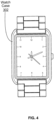
- FIG. 4 depicts a top surface of the watch band 300, in accordance with an embodiment of the invention when the watch band 300 is attached to a watch case 302.
- FIG. 5 depicts a side view of the watch band 300 attached to the watch case 302, in accordance with an embodiment of the invention.
- the side view of the watch band 300 includes the features discussed above with regard to FIG. 3 .
- the side view of the watch band 300 includes a first portion 330, a second portion 340, an example rigid link 350, and an attachment structure comprising a pair of offset links 360 and 370.
- the attachment structure comprising the pair of offset links 360 and 370 enables the watch band 300 to curl around a user's wrist while maintaining the watch case 302 at a low profile above the first portion 330.
- FIG. 6 depicts a top surface of the watch band 300, in accordance with an embodiment of the invention.
- the top surface of the watch band 300 includes the features discussed above with regard to FIG. 3 .
- the top surface of the watch band 300 includes a first portion 330, a second portion 340, an example rigid link 350, an attachment structure comprising a pair of offset links 360 and 370, and a sizing component 390.
- FIG. 7 depicts a bottom surface of the watch band 300, in accordance with an embodiment of the invention.
- the bottom surface of the watch band 300 includes the features discussed above with regard to FIG. 3 . Specifically, the bottom surface of the watch band 300 shows the first portion 330, the second portion 340, the example rigid link 350 of the second portion 340, the pair of offset links 360 and 370, and the sizing component 390.
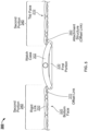
- FIG. 8 is a an enlarged partial phantom side view of the watch band 300, in accordance with an embodiment of the invention.
- the phantom side view of the watch band 300 shows the features discussed above with regard to FIG. 3 .
- the phantom side view of the watch band 300 shows the top surface 310, the bottom surface 320, the second portion 340, the example rigid link 350 of the second portion 340, the detachment component 380, and the sizing component 390.
- the first portion of the watch band 300 is not visible in FIG. 8 .
- the detachment component 380 is a pivoting snap-style clasp.
- FIG. 9 is a an enlarged partial phantom view of the top surface of the watch band 300, in accordance with an embodiment of the invention.
- the phantom view of the top surface includes the features discussed above with regard to FIG. 3 .
- the phantom top view of the watch band 300 shows some of the second portion 340, the example rigid link 350 of the second portion 340, the detachment component 380, and the sizing component 390.
- the first portion of the watch band 300 is not visible in FIG. 9 .
- Embodiments of another aspect of the invention also include a method of attaching a watch band to a watch case.
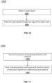
- FIG. 10 illustrates a flow chart of a method 1000 for attaching a watch band to a watch case in accordance with various embodiments of the invention.
- the method 1000 includes steps of obtaining 1001 a watch band and sliding 1002 the watch band through two lugs of the watch case.
- the watch band obtained in step 1001 of the method 1000 is an embodiment of the watch bands discussed in detail above with regard to FIGS. 3-9 .
- the watch band obtained in step 1001 includes a first portion and a second portion continuous with the first portion.
- the first portion of the watch band is made of a first material.
- the second portion of the watch band includes a series of rigid links that are formed from a second material that is different than the first material.
- the first material of the first portion and the second material of the second portion may be a polymer, an elastomer, a metal, a fabric, a mesh, a composite material, and/or any combination thereof.
- the watch band is slid through two lugs of the watch case such that the first portion of the watch band is located directly under a back of the watch case and such that the second portion of the watch band is adapted to wrap around a wrist of a user.
- the first material of a portion of the watch band is a flexible material
- the flexibility of the first material enables the first portion to be easily pulled through lugs of a watch case without becoming stuck.
- the watch band obtained in step 1001 of the method 1000 further includes an attachment structure that attaches the first portion to the second portion of the watch band.
- the attachment structure comprises at least one offset link.
- the method 1000 further includes coupling the at least one offset link to a lug of the watch case to prevent relative sliding between the watch case and the watch band.
- the offset links couple to the lugs of the watch case such that the first portion of the watch band is directed downwards and away from the watch case. This downward direction of the first portion of the watch band by the offset links enables a second portion of the watch band to be at the same level as the watch case when wrapped around a wrist of a user. This permits the first portion of the watch band to be neatly disposed below the watch case.
- the second portion of the watch band obtained in step 1001 of the method 1000 further includes a detachment component that is disposed remotely from the first portion of the watch band.
- the method 1000 can further include detaching the detachment component prior to sliding 1002 the watch band through two lugs of the watch case.
- the method 1000 can further include attaching the detachment component after sliding 1002 the watch band through two lugs of the watch case.
- the watch band can also include a sizing component that is different than the detachment component.
- the sizing component can be a butterfly clasp.
- Embodiments of the invention also include a method of manufacturing a single-piece watch band.
- FIG. 11 illustrates a flow chart of a method 1100 for manufacturing a watch band in accordance with an embodiment of the invention. As shown in FIG. 11 , the method 1100 includes the steps of forming 1101 a first portion of the watch band from a first material and forming 1102 a second portion continuous with the first portion of the watch band from a different second material.
- the watch band manufactured by the method 1100 is an embodiment of the watch bands discussed in detail above with regard to FIGS. 3-10 .
- the first portion of the watch band is adapted to be located directly under a back of a watch case, when the watch case is attached to the watch band.
- the second portion of the watch band includes a series of rigid links, and is adapted to wrap around a wrist of a user, when the watch band is worn by the user.
- the first material of the first portion of the watch band and the second material of the second portion of the watch band may be a polymer, an elastomer, a metal, a fabric, a mesh, a composite material, and/or any combination thereof.
- the method 1100 further includes a step of forming an attachment structure to attach the first portion of the watch band to the second portion of the watch band.
- the attachment structure comprises at least one offset link. The at least one offset link is adapted to couple to a lug of a watch case when the watch case is attached to the watch band, to prevent relative sliding between the watch case and the watch band.
- forming 1102 a second portion continuous with the first portion of the watch band from a different second material further includes incorporating a detachment component disposed remotely from the first portion of the watch band.
- forming 1102 a second portion continuous with the first portion of the watch band from a different second material can further include incorporating a sizing component that is different than the detachment component.
- the sizing component can be a butterfly clasp.
Landscapes
- Professional, Industrial, Or Sporting Protective Garments (AREA)
- Adornments (AREA)
Description
- This application claims priority to and the benefit of
U.S. Provisional Patent Application No. 63/039,963, which was filed on June 16, 2020 - In various embodiments, the invention relates generally to watch bands and, more particularly, to single-piece watch bands.
- Many conventional watch bands are two-piece watch bands having two separate band components.
FIG. 1 illustrates one example of a conventional two-piece watch band 100. As shown inFIG. 1 , in a conventional two-piece watch band, each separate band component includes a loop through which a removable portion (e.g., a spring-loaded pin) of a watch case lug is inserted. When the removable portions are secured within the lug, the separate watch band components are secured to the watch case and the watch can be worn by a user. However, such removal and re-attachment of the removeable portions to the watch case can require specific tools and can be inconvenient. - Another known type of watch band is the NATO watch band or strap.
FIG. 2 illustrates an example conventional NATOwatch band 200. As shown inFIG. 2 , conventional NATO watch bands are made of a flexible, non-rigid material (e.g., a fabric) to allow the watch band to be easily inserted through the spring-loaded pins or through fixed lugs on a watch case. However, because this insertion technique relies upon the flexibility and non-rigidity of the NATO watch band, NATO watch bands are not made from rigid materials, which limits the types of materials and styles that can be offered by a NATO watch band. - An improved watch band that addresses the shortcomings of existing watch bands is needed.
US 2015/342308 A1 discloses a wearable electronic device holder having a retention member for retaining an electronic device, such as a smartwatch or an MP3 player, and a wrist strap attached to the retention member is disclosed. The retention member includes a protective frame comprising one or more covers or openings for receiving and allowing interaction with one or more buttons, knobs, and/or ports of the electronic device. At least one of the covers is configured to enable the dual-action functionality of a knob of the electronic device. The protective frame may also include an opening adapted to receive sound-permeable, waterproof inserts for an audio port of the electronic device. The protective frame further includes fastening holes for attachment to the wrist strap. The protective frame may be a two-piece frame that partially encloses the electronic device. - The present invention relates to an improved single-piece watch band assembly that can be formed from more rigid materials (e.g., a series of rigid links) than NATO bands. Several inventive features of the watch band described herein enable it to function better and provide more design and style choices than conventional watch bands.
- In one aspect, the invention relates to a watch band according to
claim 1. In some embodiments, the first material of the first portion and the second material of the second portion may be a polymer, an elastomer, a metal, a fabric, a mesh, a composite material, and/or combinations thereof. In certain further embodiments, the first material of the first portion can be rubber and the second material of the second portion can be metal. - The watch band further includes an attachment structure that attaches the first portion of the watch band to the second portion of the watch band. The attachment structure comprises at least one offset link. The offset link is adapted to couple to a lug of the watch case to prevent relative sliding movement therebetween. In further embodiments, the offset link can be a pair of offset links, each offset link adapted to couple to a respective lug of the watch case.
- In some embodiments, the second portion of the watch band can include a detachment component that is disposed remotely from the first portion of the watch band. In such embodiments the watch band can further include a sizing component that is different than the detachment component. The sizing component can be a butterfly clasp in certain embodiments.
- In another aspect, the invention relates to a method of manufacturing a watch band according to
claim 2. - In some embodiments, the first material of the first portion and the second material of the second portion may be a polymer, an elastomer, a metal, a fabric, a mesh, a composite material, and/or combinations thereof. The method further includes the step of forming an attachment structure that attaches the first portion of the watch band to the second portion of the watch band. The attachment structure comprises at least one offset link. The offset link is adapted to couple to a lug of the watch case to prevent relative sliding movement therebetween. In further embodiments, the offset link can be a pair of offset links, each offset link adapted to couple to a respective lug of the watch case.
- In some embodiments, the step of forming the second portion of the watch band can include incorporating a detachment component into the second portion of the watch band and disposed remotely from the first portion of the watch band. In such embodiments, the step of forming the second portion of the watch band can further include incorporating a sizing component into the second portion of the watch band that is different than the detachment component. The sizing component can be a butterfly clasp.
- In another aspect, the invention relates to a method of attaching a watch band to a watch case according to
claim 5. - In some embodiments, the first material of the first portion and the second material of the second portion may be a polymer, an elastomer, a metal, a fabric, a mesh, a composite material, and/or combinations thereof. The watch band further includes an attachment structure that attaches the first portion of the watch band to the second portion of the watch band. The attachment structure comprises at least one offset link. The method includes the step of coupling the offset link to a lug of the watch case to prevent relative sliding movement therebetween. In further embodiments, the offset link can be a pair of offset links and the coupling step can include coupling each offset link to a respective lug of the watch case.
- In some embodiments, the second portion of the watch band can further include a detachment component disposed remotely from the first portion of the watch band. In such embodiments, the method can further include the step of detaching the detachment component, prior to the step of sliding the watch band through two lugs of the watch case. In further embodiments, the method can further include the step of attaching the detachment component after the step of sliding the watch band through two lugs of the watch case.
- In some embodiments, the watch band can further include a sizing component that is different than the detachment component. In such embodiments, the sizing component can be a butterfly clasp.
- These and other features, aspects, and advantages of embodiments of the present invention will become better understood with regard to the following description, and accompanying drawings, where:
-
FIG. 1 depicts an example of a conventional two-piece watch band; -
FIG. 2 depicts an example of a conventional NATO watch band; -
FIG. 3 is a schematic side view of a watch band, in accordance with various embodiments of the invention; -
FIG. 4 is a schematic perspective view of the watch band attached to a watch case, in accordance with various embodiments of the invention; -
FIG. 5 is a schematic side view of the watch band attached to a watch case, in accordance with various embodiments of the invention; -
FIG. 6 is a schematic top view of the watch band, in accordance with various embodiments of the invention; -
FIG. 7 is a schematic bottom view of the watch band, in accordance with various embodiments of the invention; -
FIG. 8 is a schematic enlarged partial phantom side view of a detachment component, in accordance with various embodiments of the invention; -
FIG. 9 is a schematic enlarged partial phantom top view of the watch band, in accordance with various embodiments of the invention; -
FIG. 10 is a flow chart of a method for attaching a watch band to a watch case, in accordance with various embodiments of the invention; and -
FIG. 11 is a flow chart of a method for manufacturing a watch band, in accordance with various embodiments of the invention. - The figures depict various embodiments of the present invention for purposes of illustration only. One skilled in the art will readily recognize from the following discussion that alternative embodiments of the structures and methods illustrated herein can be employed without departing from the principles of the embodiments of the invention described herein, the invention being defined by the appended claims.
- Embodiments of the invention include an
improved watch band 300.FIG. 3 is a side view of thewatch band 300, in accordance with various embodiments of the invention. Thewatch band 300 can include atop surface 310 and abottom surface 320. As shown inFIG. 3 , thewatch band 300 is a single, continuous band, and includes afirst portion 330 attached to asecond portion 340, such that thefirst portion 330 and thesecond portion 340 are continuous with one another. As used herein, the term single piece means that all of the components are attached such that no component has complete freedom of motion with respect to any other component. The term does not require that the structure be monolithic or be formed from a single component, but can be an assembly of components. Thesecond portion 340 of thewatch band 300 includes a series of rigid links, including examplerigid link 350. - The
first portion 330 of thewatch band 300 is made of a first material and is adapted to be located directly under a back of awatch case 302, when thewatch case 302 is attached to thewatch band 300. The rigid links of thesecond portion 340 are made of a second material that is different from the first material. Thesecond portion 340 of thewatch band 300 is adapted to wrap around a wrist of a user when thewatch band 300 is worn by the user. In some embodiments, the first material of thefirst portion 330 and the second material of thesecond portion 340 can be a polymer, an elastomer, a metal, a fabric, a mesh, a composite material, and/or any combination thereof. In certain further embodiments, the first material of thefirst portion 330 is rubber and the second material of thesecond portion 340 is metal. In embodiments in which the first material of thefirst portion 330 is a flexible material, such as rubber, the flexibility of the first material can enable thefirst portion 330 to conform to a wrist of a user, when the user wears thewatch band 300, and also can enable thefirst portion 330 to be easily pulled through lugs of a watch case without becoming stuck. - The
first portion 330 and thesecond portion 340 of thewatch band 300 are attached and are continuous with one another, such that thewatch band 300 is a single, continuous piece not intended to be disassembled by a user. If a conventional rigid watch band were attempted to be pulled through two lugs of thewatch case 302, that the watch band would not fit or would be too rigid to properly curl around a user's wrist and also permit thewatch case 302 to lay flat against the wrist. - According to the invention depicted in
FIG. 3 , anattachment structure 360 attaches thefirst portion 330 to thesecond portion 340. According to the invention, theattachment structure 360 comprises at least one offsetlink link watch case 302 is attached to thewatch band 300. An example benefit of this configuration is to prevent relative sliding between thewatch case 302 and thewatch band 300. The offsetlinks watch case 302, can alter the trajectory of thewatch band 300 such that it is better able to wrap around a user's wrist than if the offsetlinks band 300 can be used in addition to the offsetlinks - In some embodiments, the one or more offset links couple to the lugs of the watch case such that the
first portion 330 of thewatch band 300 is directed downwards and away from the watch case. This downward direction of thefirst portion 330 of thewatch band 300 by the offset links enables thesecond portion 340 of thewatch band 300 to be at the same level as the watch case when wrapped around a wrist of a user. This permits thefirst portion 330 of thewatch band 300 to be neatly disposed below the watch case. - In some embodiments, e.g., depicted in
FIG. 3 , thesecond portion 340 of thewatch band 300 can further include adetachment component 380 that is disposed remotely from thefirst portion 330 of thewatch band 300. In other words, when thewatch band 300 is attached to a watch case, thedetachment component 380 enables thewatch band 300 to be detached at a location remote from the watch case. This allows thewatch band 300 to be pulled through the watch case lugs while permitting using a conventional technique for lengthening and shortening the watch band (e.g., a jeweler's or butterfly clasp) to facilitate donning and removal of the watch from a user's wrist. Conventional two-piece watch bands only have a detachment portion at the location where they attach to the watch case or where the slack is removed from the band. For a user to be able to direct the single-piece watch band 300 under the watch case, it can be advantageous for thewatch band 300 to have a detachment point remote from the watch case and different from the sizing component. Thedetachment component 380 is depicted in further detail inFIG. 8 . - In embodiments in which the
second portion 340 of thewatch band 300 further includes thedetachment component 380, thewatch band 300 can also include asizing component 390 that is different than thedetachment component 380. In general, any known sizing component can be used, e.g., a butterfly clasp. - Because the
detachment component 380 is both disposed remotely from thefirst portion 300 of thewatch band 300 and is different than thesizing component 390, thewatch band 300 can be pulled through the lugs of a watch case for wear by a user before being sized to the user's wrist. -
FIG. 4 depicts a top surface of thewatch band 300, in accordance with an embodiment of the invention when thewatch band 300 is attached to awatch case 302. -
FIG. 5 depicts a side view of thewatch band 300 attached to thewatch case 302, in accordance with an embodiment of the invention. The side view of thewatch band 300 includes the features discussed above with regard toFIG. 3 . Specifically, the side view of thewatch band 300 includes afirst portion 330, asecond portion 340, an examplerigid link 350, and an attachment structure comprising a pair of offsetlinks links watch band 300 to curl around a user's wrist while maintaining thewatch case 302 at a low profile above thefirst portion 330. -
FIG. 6 depicts a top surface of thewatch band 300, in accordance with an embodiment of the invention. The top surface of thewatch band 300 includes the features discussed above with regard toFIG. 3 . Specifically, the top surface of thewatch band 300 includes afirst portion 330, asecond portion 340, an examplerigid link 350, an attachment structure comprising a pair of offsetlinks sizing component 390. -
FIG. 7 depicts a bottom surface of thewatch band 300, in accordance with an embodiment of the invention. The bottom surface of thewatch band 300 includes the features discussed above with regard toFIG. 3 . Specifically, the bottom surface of thewatch band 300 shows thefirst portion 330, thesecond portion 340, the examplerigid link 350 of thesecond portion 340, the pair of offsetlinks sizing component 390. -
FIG. 8 is a an enlarged partial phantom side view of thewatch band 300, in accordance with an embodiment of the invention. The phantom side view of thewatch band 300 shows the features discussed above with regard toFIG. 3 . Specifically, the phantom side view of thewatch band 300 shows thetop surface 310, thebottom surface 320, thesecond portion 340, the examplerigid link 350 of thesecond portion 340, thedetachment component 380, and thesizing component 390. The first portion of thewatch band 300 is not visible inFIG. 8 . In this embodiment, thedetachment component 380 is a pivoting snap-style clasp. -
FIG. 9 is a an enlarged partial phantom view of the top surface of thewatch band 300, in accordance with an embodiment of the invention. The phantom view of the top surface includes the features discussed above with regard toFIG. 3 . Specifically, the phantom top view of thewatch band 300 shows some of thesecond portion 340, the examplerigid link 350 of thesecond portion 340, thedetachment component 380, and thesizing component 390. The first portion of thewatch band 300 is not visible inFIG. 9 . - Embodiments of another aspect of the invention also include a method of attaching a watch band to a watch case.
FIG. 10 illustrates a flow chart of amethod 1000 for attaching a watch band to a watch case in accordance with various embodiments of the invention. Themethod 1000 includes steps of obtaining 1001 a watch band and sliding 1002 the watch band through two lugs of the watch case. - The watch band obtained in
step 1001 of themethod 1000 is an embodiment of the watch bands discussed in detail above with regard toFIGS. 3-9 . Specifically, the watch band obtained instep 1001 includes a first portion and a second portion continuous with the first portion. The first portion of the watch band is made of a first material. The second portion of the watch band includes a series of rigid links that are formed from a second material that is different than the first material. In some embodiments, the first material of the first portion and the second material of the second portion may be a polymer, an elastomer, a metal, a fabric, a mesh, a composite material, and/or any combination thereof. - In
step 1002 of themethod 1000, the watch band is slid through two lugs of the watch case such that the first portion of the watch band is located directly under a back of the watch case and such that the second portion of the watch band is adapted to wrap around a wrist of a user. In embodiments in which the first material of a portion of the watch band is a flexible material, the flexibility of the first material enables the first portion to be easily pulled through lugs of a watch case without becoming stuck. - As discussed with regard to
FIGS. 3-9 , according to the invention, the watch band obtained instep 1001 of themethod 1000 further includes an attachment structure that attaches the first portion to the second portion of the watch band. The attachment structure comprises at least one offset link. According to the invention, themethod 1000 further includes coupling the at least one offset link to a lug of the watch case to prevent relative sliding between the watch case and the watch band. - In some embodiments, the offset links couple to the lugs of the watch case such that the first portion of the watch band is directed downwards and away from the watch case. This downward direction of the first portion of the watch band by the offset links enables a second portion of the watch band to be at the same level as the watch case when wrapped around a wrist of a user. This permits the first portion of the watch band to be neatly disposed below the watch case.
- In some embodiments, the second portion of the watch band obtained in
step 1001 of themethod 1000 further includes a detachment component that is disposed remotely from the first portion of the watch band. In such embodiments, themethod 1000 can further include detaching the detachment component prior to sliding 1002 the watch band through two lugs of the watch case. In further embodiments, themethod 1000 can further include attaching the detachment component after sliding 1002 the watch band through two lugs of the watch case. - In certain embodiments in which the second portion of the watch band further includes the detachment component, the watch band can also include a sizing component that is different than the detachment component. In certain embodiments, the sizing component can be a butterfly clasp. As mentioned above, because the detachment component is both disposed remotely from the first portion of the watch band, and is different than the sizing component, the detachment component can be detached, the watch band can be pulled through the lugs of the watch case, and then the detachment component can be attached for wear by a user while permitting using a conventional technique for lengthening and shortening the watch band (e.g., a jeweler's or butterfly clasp) to facilitate donning and removal of the watch from a user's wrist.
- Embodiments of the invention also include a method of manufacturing a single-piece watch band.
FIG. 11 illustrates a flow chart of amethod 1100 for manufacturing a watch band in accordance with an embodiment of the invention. As shown inFIG. 11 , themethod 1100 includes the steps of forming 1101 a first portion of the watch band from a first material and forming 1102 a second portion continuous with the first portion of the watch band from a different second material. - The watch band manufactured by the
method 1100 is an embodiment of the watch bands discussed in detail above with regard toFIGS. 3-10 . The first portion of the watch band is adapted to be located directly under a back of a watch case, when the watch case is attached to the watch band. The second portion of the watch band includes a series of rigid links, and is adapted to wrap around a wrist of a user, when the watch band is worn by the user. - In some embodiments, the first material of the first portion of the watch band and the second material of the second portion of the watch band may be a polymer, an elastomer, a metal, a fabric, a mesh, a composite material, and/or any combination thereof.
- According to the invention, the
method 1100 further includes a step of forming an attachment structure to attach the first portion of the watch band to the second portion of the watch band. According to the invention, the attachment structure comprises at least one offset link. The at least one offset link is adapted to couple to a lug of a watch case when the watch case is attached to the watch band, to prevent relative sliding between the watch case and the watch band. - In some embodiments, forming 1102 a second portion continuous with the first portion of the watch band from a different second material further includes incorporating a detachment component disposed remotely from the first portion of the watch band. In such embodiments, forming 1102 a second portion continuous with the first portion of the watch band from a different second material can further include incorporating a sizing component that is different than the detachment component. In certain embodiments, the sizing component can be a butterfly clasp.
Claims (13)
- A watch band (300) comprising:a first portion (330) comprising a first material adapted to be located directly under a back of a watch case (302);a second portion (340) comprising a series of rigid links formed from a different second material and adapted to wrap around a wrist of a user; andan attachment structure (360) attaching the first portion (330) to the second portion (340) such that the second portion (340) is continuous with the first portion (330), characterized in that the attachment structure (360) comprises at least one offset link (360, 370) adapted to couple to a lug of the watch case (302) to prevent relative sliding movement therebetween.
- A method of manufacturing a watch band (300), the method comprising the steps of:forming a first portion (330) from a first material, the first portion (330) adapted to be located directly under a back of a watch case (302);forming a second portion (340) from a different second material, the second portion (340) comprising a series of rigid links and being adapted to wrap around a wrist of a user; andforming an attachment structure (360) attaching the first portion (330) to the second portion (340) such that the second portion (340) is continuous with the first portion (330), the attachment structure (360) comprising at least one offset link (360, 370) adapted to couple to a lug of the watch case (302) to prevent relative sliding movement therebetween.
- The watch band (300) of claim 1 or the method of claim 2, wherein the at least one offset link (360, 370) comprises a pair of offset links, each offset link (360, 370) adapted to couple to a respective lug of the watch case (302).
- The method of claim 2, wherein:i) the step of forming the second portion (340) comprises incorporating a detachment component (380) disposed remotely from the first portion (330); and optionallyii) the step of forming the second portion (340) further comprises incorporating a sizing component (390) different than the detachment component (380).
- A method of attaching a watch band (300) to a watch case (302), the method comprising the steps of:obtaining the watch band (300) comprising:a first portion (330) comprising a first material; anda second portion (340) continuous with the first portion (330) and comprising a series of rigid links formed from a different second material; andsliding the watch band (300) through two lugs of the watch case (302), such that (i) the first portion (330) is located directly under a back of the watch case (302) and (ii) the second portion (340) is adapted to wrap around a wrist of a user,wherein the watch band further comprises an attachment structure attaching the first portion to the second portion, wherein the attachment structure comprises at least one offset link (360, 370), the method further comprising the step of coupling the at least one offset link (360, 370) to a lug of the watch case (302) to prevent relative sliding movement therebetween.
- The watch band (300) of claim 1 or the method of claim 2 or claim 5, wherein the first material and the second material are selected from the group consisting of a polymer, an elastomer, a metal, a fabric, a mesh, a composite material, and combinations thereof.
- The watch band (300) of claim 6 wherein the first material comprises a rubber and the second material comprises a metal.
- The method of claim 5, wherein the at least one offset link (360, 370) comprises a pair of offset links (360, 370), wherein the coupling step comprises coupling each offset link (360, 370) to a respective lug of the watch case (302).
- The watch band (300) of claim 1 or the method of claim 5, wherein the second portion (340) comprises a detachment component (380) disposed remotely from the first portion (330).
- The method of claim 9, further comprising, prior to the sliding step, the step of detaching the detachment component (380).
- The method of claim 10, further comprising, after the sliding step, the step of attaching the detachment component (380).
- The watch band (300) of claim 9 or the method of claim 9, wherein the watch band (300) further comprises a sizing component (390) different than the detachment component (380).
- The watch band (300) of claim 12 or the method of claim 4 part ii) or claim 12, wherein the sizing component (390) comprises a butterfly clasp.
Applications Claiming Priority (2)
| Application Number | Priority Date | Filing Date | Title |
|---|---|---|---|
| US202063039963P | 2020-06-16 | 2020-06-16 | |
| PCT/US2021/037351 WO2021257517A1 (en) | 2020-06-16 | 2021-06-15 | Single-piece watch band |
Publications (2)
| Publication Number | Publication Date |
|---|---|
| EP4164448A1 EP4164448A1 (en) | 2023-04-19 |
| EP4164448B1 true EP4164448B1 (en) | 2025-01-01 |
Family
ID=76797177
Family Applications (1)
| Application Number | Title | Priority Date | Filing Date |
|---|---|---|---|
| EP21737943.7A Active EP4164448B1 (en) | 2020-06-16 | 2021-06-15 | Single-piece watch band |
Country Status (5)
| Country | Link |
|---|---|
| US (1) | US11819096B2 (en) |
| EP (1) | EP4164448B1 (en) |
| CN (1) | CN116249462B (en) |
| ES (1) | ES3003534T3 (en) |
| WO (1) | WO2021257517A1 (en) |
Families Citing this family (3)
| Publication number | Priority date | Publication date | Assignee | Title |
|---|---|---|---|---|
| USD977359S1 (en) * | 2021-11-05 | 2023-02-07 | Feini Lan | Watch strap |
| USD970381S1 (en) * | 2021-11-09 | 2022-11-22 | Heling Tian | Watchband |
| USD979443S1 (en) * | 2022-01-05 | 2023-02-28 | Xilian Wu | Hollow-carved watchband |
Family Cites Families (126)
| Publication number | Priority date | Publication date | Assignee | Title |
|---|---|---|---|---|
| US1892281A (en) | 1931-08-04 | 1932-12-27 | Kestenman Bros Mfg Co | Clasp for bracelets, straps, linkages, or the like |
| US2159857A (en) | 1938-12-23 | 1939-05-23 | Hickok Mfg Co Inc | Reversible belt |
| US2432661A (en) | 1943-09-24 | 1947-12-16 | Brite Specialty Company | Wrist watch strap |
| US2453616A (en) | 1944-06-06 | 1948-11-09 | Berstell Leo | Watch bezel |
| US2400222A (en) | 1945-02-23 | 1946-05-14 | Thelma B Cline | Wrist purse |
| US2439274A (en) | 1947-09-13 | 1948-04-06 | Spector Theodore | Wrist band or strap for watches |
| US2653442A (en) | 1950-11-08 | 1953-09-29 | Benrus Watch Company Inc | Retainer for initials or other indicia, and a watch construction containing same |
| US2895658A (en) | 1954-02-25 | 1959-07-21 | Dzus William | Wrist guard or protector |
| CH319691A (en) | 1955-04-16 | 1957-02-28 | Movado Montres | Wristwatch |
| DE1122309B (en) * | 1960-10-07 | 1962-01-18 | Lewa G M B H | watch strap |
| US3361311A (en) | 1966-03-15 | 1968-01-02 | Sartarelli Umberto | Adjustable wristbands |
| US3673795A (en) | 1970-04-16 | 1972-07-04 | Carlon Eng Co Inc | Expansible wrist band |
| US3706404A (en) | 1970-09-24 | 1972-12-19 | Gerald W Gluckin | Stretch fabric watchband |
| FR2410452A1 (en) | 1977-11-30 | 1979-06-29 | Galais Claudy | Watch strap with no fastener - is made of elastic material with ends sewn or stuck together at join underneath watch case |
| GB2048650A (en) | 1979-05-10 | 1980-12-17 | Timex Corp | One-piece watch strap |
| US4314389A (en) | 1979-10-04 | 1982-02-09 | B. A. Ballou & Co., Incorporated | Double fold over jewelry clasp |
| KR840002099B1 (en) | 1980-04-25 | 1984-11-15 | 마티우 노오쓰 진 | Elastic bracelet |
| CH650891GA3 (en) | 1983-01-28 | 1985-08-30 | ||
| JPS61168302A (en) | 1984-12-25 | 1986-07-30 | シチズン時計株式会社 | Middle metal clasp of clock band |
| CH666783GA3 (en) | 1986-12-17 | 1988-08-31 | ||
| US4742503A (en) | 1987-05-28 | 1988-05-03 | E. Gluck Corporation | Watch assembly having interchangeable bezels and coordinated interchangeable bands |
| AU7792087A (en) * | 1987-09-10 | 1989-03-09 | Terence Chi | Pen watchband |
| US5215235A (en) | 1988-02-16 | 1993-06-01 | Citizen Watch Co., Ltd. | Watch band |
| DE3832614C1 (en) | 1988-09-26 | 1989-11-16 | Iwc International Watch Co. Ag, Schaffhausen, Ch | |
| FR2637469B1 (en) | 1988-10-11 | 1991-01-11 | Bouveret Gerard | REMOVABLE WATCH SUPPORT DEVICE |
| IT1234489B (en) | 1989-02-06 | 1992-05-18 | Chimento Adriano S P A | METHOD OF COMPOSITION OF MANUFACTURES SUITABLE FOR MAKING NECKLACES, BRACELETS OR SIMILAR OBJECTS AND OBJECTS MADE WITH THE SAID METHOD |
| IT217031Z2 (en) | 1989-04-21 | 1991-10-29 | Chevalley Gianandrea | CLOSING DEVICE OF A WATCH STRAP |
| CH680327GA3 (en) | 1990-10-10 | 1992-08-14 | Wrist watch with interchangeable supports - includes slotted base which may receive key or conventional strap | |
| ITMI910764U1 (en) | 1991-09-06 | 1993-03-06 | Gtf Srl | CLOSING DEVICE FOR WATCH BRACELETS IN METAL OF FABRIC OR SPILED TYPE, BRACELETS, JEWELRY AND SIMILAR |
| IT1252579B (en) | 1991-12-23 | 1995-06-19 | Gtf Srl | JOINTED WALLET CLOSURE FOR WATCH BRACELETS, BRACELETS, JEWELRY AND SIMILAR |
| US5333123A (en) | 1993-07-23 | 1994-07-26 | Timex Corporation | Continuous waterproof timepiece case with integral case back blank |
| JP3477773B2 (en) | 1993-12-16 | 2003-12-10 | セイコーエプソン株式会社 | Watch band clasp, watch band, and watch |
| US5711056A (en) | 1994-05-20 | 1998-01-27 | Citizen Watch Co., Ltd. | Buckle for a personal adornment band |
| JPH08238116A (en) | 1995-03-07 | 1996-09-17 | Casio Comput Co Ltd | Band mounting structure |
| WO1996028064A1 (en) | 1995-03-15 | 1996-09-19 | Citizen Watch Co., Ltd. | Device for fine adjustment of length of band-shaped accessory |
| JPH09234104A (en) | 1996-03-01 | 1997-09-09 | Citizen Watch Co Ltd | Movable end fitting part of watch case |
| CH690116A5 (en) | 1996-07-17 | 2000-05-15 | Rolex Montres | Device for adjusting the length of a wristband with a clasp with unfolding blades. |
| JP3964492B2 (en) | 1997-03-26 | 2007-08-22 | シチズンホールディングス株式会社 | Watch band mounting structure |
| EP0999765B1 (en) | 1997-07-28 | 2004-06-09 | Tag-Heuer S.A. | Unfolding clasp for wrist band |
| US6073821A (en) | 1998-11-10 | 2000-06-13 | Mercer; Lance | Closed-loop adjustable watch band |
| JP2000253913A (en) | 1999-03-11 | 2000-09-19 | Citizen Watch Co Ltd | Connection structure for watch case to band, and band piece to band piece |
| US20070000283A1 (en) | 1999-09-01 | 2007-01-04 | Murao Co., Ltd. | Structure for adjusting length of ornament chains |
| JP2001169808A (en) | 1999-12-20 | 2001-06-26 | Seiko Instruments Inc | Arm portable information device arm holder |
| US6415483B1 (en) | 2000-07-06 | 2002-07-09 | Downey Dang | Jewelry clasp |
| US6505763B2 (en) | 2000-08-02 | 2003-01-14 | Meliga Habillement Horloger Sa | Circumferentially continuous arrangement which is to be worn preferably on the wrist and has a hinged closure |
| US6921006B2 (en) | 2000-12-12 | 2005-07-26 | Tonya Daree Bauer | Quick-change watchbands |
| ITFI20010012U1 (en) | 2001-02-05 | 2002-08-05 | Nomination Di Antonio E Paolo | WATCH WITH INCORPORATING CASE A PASSAGE OF COUPLING TO A BRACELET, IN PARTICULAR BUT NOT EXCLUSIVELY OF THE TYPE WITH LINKS BOX |
| JP2002277561A (en) | 2001-03-19 | 2002-09-25 | Citizen Watch Co Ltd | Use mode change device for wristwatch |
| US6597638B2 (en) | 2001-05-25 | 2003-07-22 | Movado Group, Inc. | Apparatus and methods for attachment and detachment of watch straps |
| JP2003052422A (en) | 2001-08-20 | 2003-02-25 | Seiko Instruments Inc | Case, watchband and watch |
| GB2374516B (en) | 2002-01-02 | 2003-06-04 | Wing Hon Metal Manufactory Ltd | Band for timepiece and method of manufacturing same |
| JP2003275005A (en) | 2002-03-26 | 2003-09-30 | Seiko Instruments Inc | Wrist-mounted portable device |
| FR2842081B1 (en) | 2002-07-11 | 2004-08-27 | Chatelain Sa G & F | AUTOMATIC CLASP FOR A WATCH STRAP |
| JP2004065705A (en) | 2002-08-08 | 2004-03-04 | Citizen Watch Co Ltd | Band-like accessory |
| CN2575724Y (en) * | 2002-10-17 | 2003-09-24 | 永确公司 | Water flow controlling apparatus |
| CH701103B1 (en) | 2004-02-17 | 2010-11-30 | Lvmh Swiss Mft Sa | watchcase including a bracelet clasp. |
| WO2005083546A1 (en) | 2004-02-27 | 2005-09-09 | Simon Richard Daniel | Wearable modular interface strap |
| JP2006034654A (en) | 2004-07-28 | 2006-02-09 | Seiko Epson Corp | Couplings, watch bands and watches |
| JP4545547B2 (en) * | 2004-10-20 | 2010-09-15 | シチズンホールディングス株式会社 | Trinket structure of jewelry |
| JP2007062180A (en) | 2005-08-31 | 2007-03-15 | Sakamoto Co Ltd | Chip for decorating surface of article |
| EP1800559B1 (en) | 2005-12-23 | 2008-10-08 | The Swatch Group Management Services AG | Link comprising a casing with a lower plate and upper plate |
| US20070253290A1 (en) | 2006-04-27 | 2007-11-01 | Christopher Aire | Modular wristwatch |
| USD543122S1 (en) | 2006-05-10 | 2007-05-22 | Ronald Lafever | Combined flexible band and clip-on watch |
| DE202006007870U1 (en) * | 2006-05-15 | 2007-09-20 | Lehr, Ralf | Adapter for connecting a watch case with a stretchable link bracelet |
| JP4946178B2 (en) | 2006-05-26 | 2012-06-06 | セイコーエプソン株式会社 | Nakadome, strip-shaped jewelry and watches |
| DE202006012832U1 (en) | 2006-08-21 | 2006-10-26 | Steiner, Wolf | Wrist-strap for watch, has holder with attaching unit for fixing watch to wrist-strap, removably connected with wrist-strap and formed from leather, where wrist-strap is spring elastically formed |
| US7874722B2 (en) | 2006-08-27 | 2011-01-25 | Nike, Inc. | Watch casing integrally formed with watch band |
| WO2008035993A1 (en) | 2006-09-19 | 2008-03-27 | Multi Watch Limited | Mounting apparatus |
| WO2008084881A1 (en) | 2007-01-11 | 2008-07-17 | Four Creators Co., Ltd. | Intermediate clasp for band |
| WO2008122998A1 (en) * | 2007-04-05 | 2008-10-16 | Pirelli & C. S.P.A. | A wrist watch band comprising links |
| JP5354434B2 (en) | 2007-05-24 | 2013-11-27 | 株式会社バンビ | Three-fold type Nakadome structure for a band and a watch having the same |
| USD566579S1 (en) | 2007-07-30 | 2008-04-15 | Nga Van Tran | Combined watch and message recording device wrist band |
| WO2009131573A1 (en) | 2008-04-22 | 2009-10-29 | Relyea Gregg F | Graphic display programmable wristwatch |
| JP2010035960A (en) | 2008-08-08 | 2010-02-18 | Casio Comput Co Ltd | Band attaching structure of wrist-watch case |
| US8973399B2 (en) | 2008-09-17 | 2015-03-10 | Timebeads, Llc | Latch mechanism for a timepiece |
| EP2199877B1 (en) | 2008-11-05 | 2011-07-27 | The Swatch Group Research and Development Ltd. | Watch comprising a microphone built into the watch case |
| EP2233026B1 (en) | 2009-03-25 | 2012-06-20 | Rolex S.A. | Device and method for linking and locking two parts and ball bar |
| US8196267B2 (en) * | 2009-11-11 | 2012-06-12 | Trueposition, Inc. | Assistance required locking clasp |
| JP4746138B1 (en) | 2010-02-03 | 2011-08-10 | 一浩 藤本 | Wristband |
| US9690258B2 (en) | 2011-01-05 | 2017-06-27 | Wimo Labs LLC | Electronic device casing |
| US9101184B2 (en) * | 2011-01-05 | 2015-08-11 | Wimo Labs LLC | Electronic device casing |
| USD653564S1 (en) | 2011-02-04 | 2012-02-07 | Albert Eida | Combined watch case, time piece, and removable watch band |
| EP2502515B1 (en) | 2011-03-21 | 2013-09-04 | The Swatch Group Management Services AG | Bracelet clasp |
| CN202189236U (en) | 2011-08-09 | 2012-04-11 | 曹里军 | Novel ceramic watch |
| CH705839B1 (en) | 2011-12-16 | 2016-09-30 | The Swatch Group Man Services Ag | anti-rotation link. |
| EP2644050B1 (en) | 2012-03-27 | 2016-05-25 | Rolex S.A. | Opening clasp for bracelet |
| CH706443A1 (en) | 2012-04-27 | 2013-10-31 | Piguet & Co Horlogerie | A fastening device with an interchangeable bracelet timepiece. |
| US8960510B2 (en) | 2012-05-23 | 2015-02-24 | Mh Bertucci, Inc. | Watch band and method of securing same |
| US20140084033A1 (en) | 2012-09-21 | 2014-03-27 | Cheryl Kellond | Bi-directionally operable, toolessly changeable, strap for a wearable display |
| EP2721943B1 (en) * | 2012-10-16 | 2015-08-12 | Rolex Sa | Resilient joint for clockwork assembly |
| CN103251181B (en) | 2012-11-23 | 2016-03-02 | 裘里斯杨 | Wrist-watch and table are buckled |
| US9125460B2 (en) | 2013-08-12 | 2015-09-08 | Timex Group Usa, Inc. | Wristworn device with a releasable locking arrangement |
| CN203673249U (en) | 2013-12-13 | 2014-06-25 | 李玉鑫 | Novel watch |
| US9560900B2 (en) | 2014-06-23 | 2017-02-07 | Mauricio Pier | Adjustable watch strap |
| US9826789B2 (en) | 2014-08-09 | 2017-11-28 | Apple Inc. | Milanese band |
| US9980539B2 (en) | 2014-08-11 | 2018-05-29 | Apple Inc. | Segmented attachment device |
| US9471102B2 (en) | 2014-08-28 | 2016-10-18 | Pebble Technology, Corp. | Connection by securing device with integrated circuitry layer |
| RU2582885C1 (en) | 2014-09-30 | 2016-04-27 | Общество С Ограниченной Ответственностью "Часовой Завод Ника" | Clock with decorative case and replaceable decorative framework on strap, clock housing with replaceable decorative frame, rear cover for clock with replaceable decorative frame and replaceable decorative frame for clock with decorative housing |
| DE102014015217A1 (en) | 2014-10-16 | 2016-04-21 | Renate Fischer | Closure band system for transport of valuables on the body |
| US20160206056A1 (en) | 2014-11-20 | 2016-07-21 | Duo Watches Corporation | Mounts for a multi-watch band |
| WO2016131415A1 (en) | 2015-02-17 | 2016-08-25 | Webbem Limited | Device for carrying cordage and survival tools and method for manufacturing the same |
| EP3058840B1 (en) | 2015-02-20 | 2018-04-18 | Swatch Ag | Expandable wristwatch |
| US9781984B2 (en) | 2015-03-08 | 2017-10-10 | Apple Inc. | Dynamic fit adjustment for wearable electronic devices |
| US9498029B2 (en) | 2015-03-13 | 2016-11-22 | Google Inc. | Clasp mechanisms for wristwatch bands |
| CN204883174U (en) | 2015-08-27 | 2015-12-16 | 广东小天才科技有限公司 | Watch |
| KR101768130B1 (en) | 2015-10-23 | 2017-08-14 | 주식회사 성조파인세라믹 | Functional health bracelet |
| CN205432426U (en) | 2015-12-31 | 2016-08-10 | 天津君士潜海计时仪器有限公司 | A multifunctional watch strap |
| EP3189954A1 (en) | 2016-01-07 | 2017-07-12 | The Swatch Group Research and Development Ltd. | Bracelet and method for manufacturing thereof |
| CH712004A2 (en) | 2016-01-07 | 2017-07-14 | Swatch Group Res & Dev Ltd | Bracelet and its manufacturing process. |
| CN205353590U (en) | 2016-01-25 | 2016-06-29 | 漳州市恒丽电子有限公司 | Erect duplex core table |
| CN205988038U (en) | 2016-08-05 | 2017-03-01 | 林汝涛 | A kind of adjustable wrist-watch of size of closed loop iron chains watchband type |
| EP3335584A1 (en) | 2016-12-16 | 2018-06-20 | The Swatch Group Research and Development Ltd | Trim panel with decoration for watch or jewel and method for manufacturing same |
| CN108324261B (en) | 2017-01-20 | 2020-10-20 | 深圳邦普医疗设备系统有限公司 | Intelligent blood pressure wristwatch |
| US10952512B2 (en) | 2017-02-08 | 2021-03-23 | Amy COX | Wearable decorative band systems |
| JP2017080605A (en) | 2017-02-15 | 2017-05-18 | カシオ計算機株式会社 | Bands and watches |
| USD835522S1 (en) | 2017-02-20 | 2018-12-11 | Emmanuel Dietrich | Watch |
| CN206710814U (en) | 2017-05-16 | 2017-12-05 | 石狮市新卯自动化设备有限公司 | A kind of multifunctional intellectual wrist-watch |
| JP7322706B2 (en) | 2017-11-20 | 2023-08-08 | ソニーグループ株式会社 | Band devices, watches and endpieces |
| CN207969773U (en) | 2018-03-12 | 2018-10-16 | 东莞市亿丰钟表有限公司 | A kind of metal watchband edge sealing structure |
| CN109288211A (en) * | 2018-10-27 | 2019-02-01 | 许明秋 | A kind of easy disassembly exchanges the intelligence wearing wrist-watch of the anti-slide guide of watchband for |
| CN209167834U (en) | 2019-01-21 | 2019-07-26 | 深圳市诺嘉源科技有限公司 | A kind of dismountable multifunctional intellectual wrist-watch |
| CN109924618B (en) | 2019-03-21 | 2024-04-05 | 瑞信五金(河源)有限公司 | Self-locking watchband with bottom-pressed quick-release telescopic needle and watch with same |
| CN109907437B (en) | 2019-03-29 | 2021-06-29 | 高达皮革制品(深圳)有限公司 | Watchband manufacturing method and watch |
| CN211154104U (en) * | 2019-06-25 | 2020-08-04 | Oppo广东移动通信有限公司 | Wearables and watch straps |
| JP2023045044A (en) * | 2021-09-21 | 2023-04-03 | カシオ計算機株式会社 | Links and clocks |
| CN222259855U (en) * | 2023-12-27 | 2024-12-27 | 东莞得利钟表有限公司 | A watch head structure with replaceable dial and watch |
-
2021
- 2021-06-15 CN CN202180060849.6A patent/CN116249462B/en active Active
- 2021-06-15 US US17/348,277 patent/US11819096B2/en active Active
- 2021-06-15 WO PCT/US2021/037351 patent/WO2021257517A1/en not_active Ceased
- 2021-06-15 EP EP21737943.7A patent/EP4164448B1/en active Active
- 2021-06-15 ES ES21737943T patent/ES3003534T3/en active Active
Also Published As
| Publication number | Publication date |
|---|---|
| US11819096B2 (en) | 2023-11-21 |
| ES3003534T3 (en) | 2025-03-10 |
| WO2021257517A1 (en) | 2021-12-23 |
| CN116249462B (en) | 2026-04-14 |
| US20210386162A1 (en) | 2021-12-16 |
| EP4164448A1 (en) | 2023-04-19 |
| CN116249462A (en) | 2023-06-09 |
Similar Documents
| Publication | Publication Date | Title |
|---|---|---|
| EP0731395B1 (en) | Watch band attachment mechanism | |
| US5092067A (en) | Leather identification bracelet | |
| US6175958B1 (en) | Bulletproof vest | |
| US10149518B1 (en) | Clasp assembly for a wearable device | |
| US6023791A (en) | Swimming goggle structure | |
| US5106004A (en) | Clothing accessory | |
| CN105901849B (en) | Wrist-watch with expansion table band | |
| US11819096B2 (en) | Single-piece watch band | |
| US9693610B2 (en) | Device for fastening and unfastening watch | |
| US20240373996A1 (en) | Strap and a wearable device comprising a strap | |
| US11800911B2 (en) | Radial watch | |
| CA2775888C (en) | Quick-change watchbands | |
| JPH11239506A (en) | Watches | |
| US193342A (en) | Improvement in spurs | |
| US4359808A (en) | Adjustable length strap with non-expansible non-metallic strap members interconnected by a metallic coupling device | |
| JP5000899B2 (en) | Globe | |
| EP1074190A2 (en) | Protective wristwatch enclosure assembly for ski/snowboard gloves and jackets | |
| JP2001112520A (en) | Precision device put on arm | |
| JP6679953B2 (en) | Bands, watch bands with locks and watches | |
| JP7203036B2 (en) | folding buckle clasp | |
| JPH0956418A (en) | Stretchable carrying band and buckle for adjusting length thereof | |
| JP2010126855A (en) | Vest | |
| KR200193507Y1 (en) | A band for watch | |
| JPH10204717A (en) | Helmet | |
| JP2004129838A (en) | Belt-like accessories |
Legal Events
| Date | Code | Title | Description |
|---|---|---|---|
| STAA | Information on the status of an ep patent application or granted ep patent |
Free format text: STATUS: UNKNOWN |
|
| STAA | Information on the status of an ep patent application or granted ep patent |
Free format text: STATUS: THE INTERNATIONAL PUBLICATION HAS BEEN MADE |
|
| PUAI | Public reference made under article 153(3) epc to a published international application that has entered the european phase |
Free format text: ORIGINAL CODE: 0009012 |
|
| STAA | Information on the status of an ep patent application or granted ep patent |
Free format text: STATUS: REQUEST FOR EXAMINATION WAS MADE |
|
| 17P | Request for examination filed |
Effective date: 20221213 |
|
| AK | Designated contracting states |
Kind code of ref document: A1 Designated state(s): AL AT BE BG CH CY CZ DE DK EE ES FI FR GB GR HR HU IE IS IT LI LT LU LV MC MK MT NL NO PL PT RO RS SE SI SK SM TR |
|
| RAP1 | Party data changed (applicant data changed or rights of an application transferred) |
Owner name: 001 DEL, LLC |
|
| DAV | Request for validation of the european patent (deleted) | ||
| DAX | Request for extension of the european patent (deleted) | ||
| STAA | Information on the status of an ep patent application or granted ep patent |
Free format text: STATUS: EXAMINATION IS IN PROGRESS |
|
| 17Q | First examination report despatched |
Effective date: 20231213 |
|
| GRAP | Despatch of communication of intention to grant a patent |
Free format text: ORIGINAL CODE: EPIDOSNIGR1 |
|
| STAA | Information on the status of an ep patent application or granted ep patent |
Free format text: STATUS: GRANT OF PATENT IS INTENDED |
|
| RIC1 | Information provided on ipc code assigned before grant |
Ipc: A44C 5/24 20060101ALN20240712BHEP Ipc: G04B 37/14 20060101ALN20240712BHEP Ipc: A44C 5/10 20060101ALI20240712BHEP Ipc: A44C 5/00 20060101ALI20240712BHEP Ipc: A44C 5/14 20060101AFI20240712BHEP |
|
| RIC1 | Information provided on ipc code assigned before grant |
Ipc: A44C 5/24 20060101ALN20240802BHEP Ipc: G04B 37/14 20060101ALN20240802BHEP Ipc: A44C 5/10 20060101ALI20240802BHEP Ipc: A44C 5/00 20060101ALI20240802BHEP Ipc: A44C 5/14 20060101AFI20240802BHEP |
|
| INTG | Intention to grant announced |
Effective date: 20240816 |
|
| GRAS | Grant fee paid |
Free format text: ORIGINAL CODE: EPIDOSNIGR3 |
|
| GRAA | (expected) grant |
Free format text: ORIGINAL CODE: 0009210 |
|
| STAA | Information on the status of an ep patent application or granted ep patent |
Free format text: STATUS: THE PATENT HAS BEEN GRANTED |
|
| RAP1 | Party data changed (applicant data changed or rights of an application transferred) |
Owner name: ELC MANAGEMENT LLC |
|
| AK | Designated contracting states |
Kind code of ref document: B1 Designated state(s): AL AT BE BG CH CY CZ DE DK EE ES FI FR GB GR HR HU IE IS IT LI LT LU LV MC MK MT NL NO PL PT RO RS SE SI SK SM TR |
|
| REG | Reference to a national code |
Ref country code: GB Ref legal event code: FG4D |
|
| REG | Reference to a national code |
Ref country code: CH Ref legal event code: EP |
|
| REG | Reference to a national code |
Ref country code: DE Ref legal event code: R096 Ref document number: 602021024280 Country of ref document: DE |
|
| P01 | Opt-out of the competence of the unified patent court (upc) registered |
Free format text: CASE NUMBER: APP_66723/2024 Effective date: 20241219 |
|
| REG | Reference to a national code |
Ref country code: IE Ref legal event code: FG4D |
|
| REG | Reference to a national code |
Ref country code: ES Ref legal event code: FG2A Ref document number: 3003534 Country of ref document: ES Kind code of ref document: T3 Effective date: 20250310 |
|
| REG | Reference to a national code |
Ref country code: LT Ref legal event code: MG9D |
|
| REG | Reference to a national code |
Ref country code: NL Ref legal event code: MP Effective date: 20250101 |
|
| REG | Reference to a national code |
Ref country code: AT Ref legal event code: MK05 Ref document number: 1755340 Country of ref document: AT Kind code of ref document: T Effective date: 20250101 |
|
| PG25 | Lapsed in a contracting state [announced via postgrant information from national office to epo] |
Ref country code: NL Free format text: LAPSE BECAUSE OF FAILURE TO SUBMIT A TRANSLATION OF THE DESCRIPTION OR TO PAY THE FEE WITHIN THE PRESCRIBED TIME-LIMIT Effective date: 20250101 |
|
| PG25 | Lapsed in a contracting state [announced via postgrant information from national office to epo] |
Ref country code: FI Free format text: LAPSE BECAUSE OF FAILURE TO SUBMIT A TRANSLATION OF THE DESCRIPTION OR TO PAY THE FEE WITHIN THE PRESCRIBED TIME-LIMIT Effective date: 20250101 |
|
| PG25 | Lapsed in a contracting state [announced via postgrant information from national office to epo] |
Ref country code: PL Free format text: LAPSE BECAUSE OF FAILURE TO SUBMIT A TRANSLATION OF THE DESCRIPTION OR TO PAY THE FEE WITHIN THE PRESCRIBED TIME-LIMIT Effective date: 20250101 |
|
| PGFP | Annual fee paid to national office [announced via postgrant information from national office to epo] |
Ref country code: DE Payment date: 20250626 Year of fee payment: 5 |
|
| PGFP | Annual fee paid to national office [announced via postgrant information from national office to epo] |
Ref country code: GB Payment date: 20250618 Year of fee payment: 5 |
|
| PG25 | Lapsed in a contracting state [announced via postgrant information from national office to epo] |
Ref country code: NO Free format text: LAPSE BECAUSE OF FAILURE TO SUBMIT A TRANSLATION OF THE DESCRIPTION OR TO PAY THE FEE WITHIN THE PRESCRIBED TIME-LIMIT Effective date: 20250401 Ref country code: IS Free format text: LAPSE BECAUSE OF FAILURE TO SUBMIT A TRANSLATION OF THE DESCRIPTION OR TO PAY THE FEE WITHIN THE PRESCRIBED TIME-LIMIT Effective date: 20250501 |
|
| PG25 | Lapsed in a contracting state [announced via postgrant information from national office to epo] |
Ref country code: HR Free format text: LAPSE BECAUSE OF FAILURE TO SUBMIT A TRANSLATION OF THE DESCRIPTION OR TO PAY THE FEE WITHIN THE PRESCRIBED TIME-LIMIT Effective date: 20250101 |
|
| PG25 | Lapsed in a contracting state [announced via postgrant information from national office to epo] |
Ref country code: PT Free format text: LAPSE BECAUSE OF FAILURE TO SUBMIT A TRANSLATION OF THE DESCRIPTION OR TO PAY THE FEE WITHIN THE PRESCRIBED TIME-LIMIT Effective date: 20250502 Ref country code: LV Free format text: LAPSE BECAUSE OF FAILURE TO SUBMIT A TRANSLATION OF THE DESCRIPTION OR TO PAY THE FEE WITHIN THE PRESCRIBED TIME-LIMIT Effective date: 20250101 |
|
| PGFP | Annual fee paid to national office [announced via postgrant information from national office to epo] |
Ref country code: FR Payment date: 20250624 Year of fee payment: 5 |
|
| PG25 | Lapsed in a contracting state [announced via postgrant information from national office to epo] |
Ref country code: GR Free format text: LAPSE BECAUSE OF FAILURE TO SUBMIT A TRANSLATION OF THE DESCRIPTION OR TO PAY THE FEE WITHIN THE PRESCRIBED TIME-LIMIT Effective date: 20250402 Ref country code: BG Free format text: LAPSE BECAUSE OF FAILURE TO SUBMIT A TRANSLATION OF THE DESCRIPTION OR TO PAY THE FEE WITHIN THE PRESCRIBED TIME-LIMIT Effective date: 20250101 |
|
| PG25 | Lapsed in a contracting state [announced via postgrant information from national office to epo] |
Ref country code: AT Free format text: LAPSE BECAUSE OF FAILURE TO SUBMIT A TRANSLATION OF THE DESCRIPTION OR TO PAY THE FEE WITHIN THE PRESCRIBED TIME-LIMIT Effective date: 20250101 |
|
| PG25 | Lapsed in a contracting state [announced via postgrant information from national office to epo] |
Ref country code: CZ Free format text: LAPSE BECAUSE OF FAILURE TO SUBMIT A TRANSLATION OF THE DESCRIPTION OR TO PAY THE FEE WITHIN THE PRESCRIBED TIME-LIMIT Effective date: 20250101 |
|
| PG25 | Lapsed in a contracting state [announced via postgrant information from national office to epo] |
Ref country code: SE Free format text: LAPSE BECAUSE OF FAILURE TO SUBMIT A TRANSLATION OF THE DESCRIPTION OR TO PAY THE FEE WITHIN THE PRESCRIBED TIME-LIMIT Effective date: 20250101 |
|
| REG | Reference to a national code |
Ref country code: DE Ref legal event code: R097 Ref document number: 602021024280 Country of ref document: DE |
|
| PG25 | Lapsed in a contracting state [announced via postgrant information from national office to epo] |
Ref country code: SM Free format text: LAPSE BECAUSE OF FAILURE TO SUBMIT A TRANSLATION OF THE DESCRIPTION OR TO PAY THE FEE WITHIN THE PRESCRIBED TIME-LIMIT Effective date: 20250101 |
|
| PGFP | Annual fee paid to national office [announced via postgrant information from national office to epo] |
Ref country code: ES Payment date: 20250710 Year of fee payment: 5 |
|
| PG25 | Lapsed in a contracting state [announced via postgrant information from national office to epo] |
Ref country code: DK Free format text: LAPSE BECAUSE OF FAILURE TO SUBMIT A TRANSLATION OF THE DESCRIPTION OR TO PAY THE FEE WITHIN THE PRESCRIBED TIME-LIMIT Effective date: 20250101 |
|
| PGFP | Annual fee paid to national office [announced via postgrant information from national office to epo] |
Ref country code: IT Payment date: 20250623 Year of fee payment: 5 |
|
| PG25 | Lapsed in a contracting state [announced via postgrant information from national office to epo] |
Ref country code: EE Free format text: LAPSE BECAUSE OF FAILURE TO SUBMIT A TRANSLATION OF THE DESCRIPTION OR TO PAY THE FEE WITHIN THE PRESCRIBED TIME-LIMIT Effective date: 20250101 |
|
| PG25 | Lapsed in a contracting state [announced via postgrant information from national office to epo] |
Ref country code: RO Free format text: LAPSE BECAUSE OF FAILURE TO SUBMIT A TRANSLATION OF THE DESCRIPTION OR TO PAY THE FEE WITHIN THE PRESCRIBED TIME-LIMIT Effective date: 20250101 |
|
| PG25 | Lapsed in a contracting state [announced via postgrant information from national office to epo] |
Ref country code: SK Free format text: LAPSE BECAUSE OF FAILURE TO SUBMIT A TRANSLATION OF THE DESCRIPTION OR TO PAY THE FEE WITHIN THE PRESCRIBED TIME-LIMIT Effective date: 20250101 |
|
| PLBE | No opposition filed within time limit |
Free format text: ORIGINAL CODE: 0009261 |
|
| STAA | Information on the status of an ep patent application or granted ep patent |
Free format text: STATUS: NO OPPOSITION FILED WITHIN TIME LIMIT |
|
| REG | Reference to a national code |
Ref country code: CH Ref legal event code: L10 Free format text: ST27 STATUS EVENT CODE: U-0-0-L10-L00 (AS PROVIDED BY THE NATIONAL OFFICE) Effective date: 20251112 |
|
| 26N | No opposition filed |
Effective date: 20251002 |
|
| REG | Reference to a national code |
Ref country code: CH Ref legal event code: H13 Free format text: ST27 STATUS EVENT CODE: U-0-0-H10-H13 (AS PROVIDED BY THE NATIONAL OFFICE) Effective date: 20260127 |
|
| PG25 | Lapsed in a contracting state [announced via postgrant information from national office to epo] |
Ref country code: MC Free format text: LAPSE BECAUSE OF FAILURE TO SUBMIT A TRANSLATION OF THE DESCRIPTION OR TO PAY THE FEE WITHIN THE PRESCRIBED TIME-LIMIT Effective date: 20250101 |
|
| PG25 | Lapsed in a contracting state [announced via postgrant information from national office to epo] |
Ref country code: LU Free format text: LAPSE BECAUSE OF NON-PAYMENT OF DUE FEES Effective date: 20250615 |
|
| REG | Reference to a national code |
Ref country code: BE Ref legal event code: MM Effective date: 20250630 |
|
| PG25 | Lapsed in a contracting state [announced via postgrant information from national office to epo] |
Ref country code: IE Free format text: LAPSE BECAUSE OF NON-PAYMENT OF DUE FEES Effective date: 20250615 |
|
| PG25 | Lapsed in a contracting state [announced via postgrant information from national office to epo] |
Ref country code: BE Free format text: LAPSE BECAUSE OF NON-PAYMENT OF DUE FEES Effective date: 20250630 |
|
| PG25 | Lapsed in a contracting state [announced via postgrant information from national office to epo] |
Ref country code: CH Free format text: LAPSE BECAUSE OF NON-PAYMENT OF DUE FEES Effective date: 20250630 |