EP4164140A1 - Frequency division duplexing in multihop relay networks - Google Patents
Frequency division duplexing in multihop relay networks Download PDFInfo
- Publication number
- EP4164140A1 EP4164140A1 EP22196827.4A EP22196827A EP4164140A1 EP 4164140 A1 EP4164140 A1 EP 4164140A1 EP 22196827 A EP22196827 A EP 22196827A EP 4164140 A1 EP4164140 A1 EP 4164140A1
- Authority
- EP
- European Patent Office
- Prior art keywords
- time interval
- station
- stations
- downlink
- uplink
- Prior art date
- Legal status (The legal status is an assumption and is not a legal conclusion. Google has not performed a legal analysis and makes no representation as to the accuracy of the status listed.)
- Withdrawn
Links
- 230000005540 biological transmission Effects 0.000 claims abstract description 73
- 238000004891 communication Methods 0.000 claims abstract description 62
- 238000000034 method Methods 0.000 claims abstract description 39
- 230000007704 transition Effects 0.000 claims description 8
- 238000004590 computer program Methods 0.000 claims 1
- 238000010586 diagram Methods 0.000 description 22
- 238000012545 processing Methods 0.000 description 20
- 239000000969 carrier Substances 0.000 description 13
- 230000004044 response Effects 0.000 description 10
- 238000012937 correction Methods 0.000 description 6
- 230000008569 process Effects 0.000 description 6
- 238000006243 chemical reaction Methods 0.000 description 5
- 235000008694 Humulus lupulus Nutrition 0.000 description 4
- 102100023174 Methionine aminopeptidase 2 Human genes 0.000 description 4
- 108090000192 Methionyl aminopeptidases Proteins 0.000 description 4
- 102100028379 Methionine aminopeptidase 1 Human genes 0.000 description 3
- 101710161855 Methionine aminopeptidase 1 Proteins 0.000 description 3
- 230000008901 benefit Effects 0.000 description 3
- 238000013507 mapping Methods 0.000 description 3
- 230000015556 catabolic process Effects 0.000 description 2
- 230000000694 effects Effects 0.000 description 2
- 238000009432 framing Methods 0.000 description 2
- 238000005192 partition Methods 0.000 description 2
- 230000008054 signal transmission Effects 0.000 description 2
- 230000005641 tunneling Effects 0.000 description 2
- 101000597553 Homo sapiens Protein odr-4 homolog Proteins 0.000 description 1
- 101000687474 Homo sapiens Rhombotin-1 Proteins 0.000 description 1
- 101001111742 Homo sapiens Rhombotin-2 Proteins 0.000 description 1
- 102100024869 Rhombotin-1 Human genes 0.000 description 1
- 102100023876 Rhombotin-2 Human genes 0.000 description 1
- 101100420167 Saccharomyces cerevisiae (strain ATCC 204508 / S288c) RTG1 gene Proteins 0.000 description 1
- 101100420168 Saccharomyces cerevisiae (strain ATCC 204508 / S288c) RTG2 gene Proteins 0.000 description 1
- 230000003044 adaptive effect Effects 0.000 description 1
- 238000013459 approach Methods 0.000 description 1
- 238000013475 authorization Methods 0.000 description 1
- 239000000872 buffer Substances 0.000 description 1
- 230000010267 cellular communication Effects 0.000 description 1
- 230000001413 cellular effect Effects 0.000 description 1
- 125000004122 cyclic group Chemical group 0.000 description 1
- 230000007423 decrease Effects 0.000 description 1
- 238000013461 design Methods 0.000 description 1
- 238000005516 engineering process Methods 0.000 description 1
- 239000000284 extract Substances 0.000 description 1
- 238000000605 extraction Methods 0.000 description 1
- 238000005562 fading Methods 0.000 description 1
- 230000036039 immunity Effects 0.000 description 1
- 238000003780 insertion Methods 0.000 description 1
- 230000037431 insertion Effects 0.000 description 1
- 230000007774 longterm Effects 0.000 description 1
- 238000012986 modification Methods 0.000 description 1
- 230000004048 modification Effects 0.000 description 1
- 230000006855 networking Effects 0.000 description 1
- 230000000737 periodic effect Effects 0.000 description 1
- 230000010363 phase shift Effects 0.000 description 1
- 238000011084 recovery Methods 0.000 description 1
- 238000012552 review Methods 0.000 description 1
- 238000012546 transfer Methods 0.000 description 1
Images


Classifications
-
- H—ELECTRICITY
- H04—ELECTRIC COMMUNICATION TECHNIQUE
- H04W—WIRELESS COMMUNICATION NETWORKS
- H04W72/00—Local resource management
- H04W72/12—Wireless traffic scheduling
-
- H—ELECTRICITY
- H04—ELECTRIC COMMUNICATION TECHNIQUE
- H04B—TRANSMISSION
- H04B7/00—Radio transmission systems, i.e. using radiation field
- H04B7/24—Radio transmission systems, i.e. using radiation field for communication between two or more posts
- H04B7/26—Radio transmission systems, i.e. using radiation field for communication between two or more posts at least one of which is mobile
- H04B7/2603—Arrangements for wireless physical layer control
- H04B7/2606—Arrangements for base station coverage control, e.g. by using relays in tunnels
-
- H—ELECTRICITY
- H04—ELECTRIC COMMUNICATION TECHNIQUE
- H04W—WIRELESS COMMUNICATION NETWORKS
- H04W84/00—Network topologies
- H04W84/02—Hierarchically pre-organised networks, e.g. paging networks, cellular networks, WLAN [Wireless Local Area Network] or WLL [Wireless Local Loop]
- H04W84/04—Large scale networks; Deep hierarchical networks
- H04W84/042—Public Land Mobile systems, e.g. cellular systems
- H04W84/047—Public Land Mobile systems, e.g. cellular systems using dedicated repeater stations
Definitions
- the present invention relates to wireless communications and more particularly to a method and system for providing frequency division duplexing ("FDD”) and half-duplex frequency division duplexing (“H-FDD”) support in multihop relay networks.
- FDD frequency division duplexing
- H-FDD half-duplex frequency division duplexing
- Wireless communication networks such as cellular networks, operate by sharing resources among mobile terminals operating in the communication network. As part of the sharing process, resources are allocated by one or more controlling devices within the system.
- Certain types of wireless communication networks are used to support cell-based high speed services such as those under the family of IEEE 802.16 standards.
- the IEEE 802.16 standards are often referred to as WiMAX or less commonly as WirelessMAN or the Air Interface Standard.
- WiMAX WirelessMAX
- WirelessMAN WirelessMAN
- Air Interface Standard Another emerging standard that has not yet been ratified
- LTE Long Term Evolution
- Other wireless networking technologies include Third Generation (3G), Third Generation Partnership Project (3GPP), and 802.11, popularly known as WiFi.
- IEEE 802.16e extends the 2004 version of IEEE 802.16 for fixed Broadband Wireless Access so as to support the mobility of users and provide Quality of Service (QoS) guarantees to enable multimedia services.
- an IEEE 802.16e cell includes a number of Mobile Stations (MSs) served by a Base Station (BS), which controls the access to the wireless medium in a centralized manner.
- MSs Mobile Stations
- BS Base Station
- a MS Before transmitting to (or receiving from) the BS, a MS must request the admission of a new connection. If accepted, the BS is then responsible for meeting the requested QoS guarantees.
- the shared wireless medium demands co-ordinated transmission of multiple traffic flows over it.
- Duplexing refers to the way two-way communication is carried on the transmission medium.
- TDD Time Division Duplex
- FDD Frequency Division Duplex
- TDD Time Division Duplex
- FDD Frequency Division Duplex
- the DL and UL traffic is typically transmitted on the same carrier frequency at different times.
- the time allocations for the DL and UL portions can be adaptive, which makes it suitable for asymmetric connections.
- FDD the UL and DL traffic is transmitted on different carrier frequencies, and may thus be transmitted/received simultaneously.
- An FDD hybrid known as Half-duplex Frequency Division Duplex (H-FDD), adds the restriction that a terminal cannot transmit and receive at the same time.
- H-FDD is cheaper to implement and less complex than full-duplex FDD, though the system throughput is lower.
- Orthogonal Frequency-Division Multiple Access OFDMA
- OFDMA Orthogonal Frequency-Division Multiple Access
- Data bursts are conveyed into two-dimensional (i.e. time and frequency) data regions, which identify regions within the frame and are advertised by the BS via specific control messages.
- Each frame is divided into downlink (DL) and uplink (UL) subframes. The former is used by the BS to transmit data to the MSs, whereas the MSs transmit to the BS in the latter.
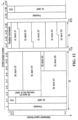
- FIG. 12 shows an example TDD frame structure.
- a DL subframe starts with a preamble followed by a Frame Control Header (FCH), a downlink MAP (DL-MAP), and an uplink MAP (UL-MAP).
- FCH Frame Control Header
- DL-MAP downlink MAP
- UL-MAP uplink MAP
- the preamble helps MSs perform synchronization and channel estimation.
- the FCH specifies a burst profile and the length of one or more downlink bursts that immediately follow the FCH in the current frame.
- the DL-MAP and UL-MAP notify MSs of the corresponding resources allocated to them in the downlink and uplink direction, respectively, within the current frame.
- the BS is free to define the shape and position of any data region.
- each MS can determine when (i.e., OFDMA symbols) and where (i.e., subchannels) it should receive from and transmit to the BS.
- Proper time gaps namely receive-to-transmit transition gap (RTG) and transmit-to-receive transition gap (TTG, also referred to herein as TRG), have to be inserted between consecutive subframes in order to give wireless devices sufficient time to switch from transmission mode to reception mode, or vice versa.
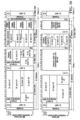
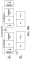
- FIG. 13 shows an example FDD frame structure.
- IEEE 802.16 specifies that BSs of FDD systems shall operate in full-duplex mode, while MSs shall be either full-duplex (FDD) or half-duplex (H-FDD).
- the FDD frame structure shown in FIG. 13 supports the concurrent operation of H-FDD and FDD MSs.
- the frame structure supports a coordinated transmission arrangement of two groups of H-FDD MSs (Group-1 and Group-2) that share the frame at distinct partitions of the frame.
- the DL frame contains two subframes.
- DL Subframe 1 comprises a preamble region, a MAP region (MAP1) and a data region (DL1).
- DL Subframe 2 comprises a MAP region (MAP2) and a data region (DL2).
- the UL frame contains two subframes, UL2 and UL1.
- FIG. 13 shows the timing relationship of the UL subframes relative to the DL subframes.
- the four parameters TTG1, TTG2, RTG1 and RTG2 are sufficiently large to accommodate the H-FDD MSs transmit receive switching time plus the round trip propagation delay.
- Group-1 H-FDD MSs listen to DL Subframe 1 and transmit in uplink subframe UL1.
- Group-2 H-FDD MSs listen to DL Subframe 2 and transmit in uplink subframe UL2.
- the MAP regions - MAP1 and MAP2 - are independent and include FCH, DL-MAP and UL-MAP.
- IEEE 802.16j adds multihop relay capabilities to IEEE 802.16 systems.
- Relay-based systems typically comprise low-cost relays, which are associated with specific base stations (BSs).
- the relays can be used to extend the coverage area of a BS and/or increase the capacity of a wireless access system.
- the relays can repeat transmissions to/from the BS so that MSs within communication range of a relay can communicate with the BS through the relay.
- the relays do not need a backhaul link because they communicate wirelessly with both BSs and MSs.
- This type of network may be referred to as a multihop network because there may be more than one wireless connection between the MS and a hardwired connection.
- a particular MS may gain network access via one or more neighbour relays and/or one or more neighbour BSs.
- relays themselves might have one or more available path options to connect to a particular BS.
- IEEE 802.16j requires that from the perspective of the MS any communications with a Multihop Relay Base Station (MR-BS) which are relayed through a Relay Station (RS) appear to be the same as if they had come directly from the BS.
- MR-BS Multihop Relay Base Station
- RS Relay Station
- the radio link between a MR-BS or RS and an MS is called an access link, while the link between a MR-BS and an RS or between a pair of RSs is called a relay link.
- IEEE 802.16j defines two different RS modes of operation: transparent and non-transparent.
- a Transparent RS does not transmit control information such as preamble, FCH, and MAP.
- An MS connected to a T-RS receives control information directly from the MR-BS, and the T-RS relays only data traffic.
- a Non-Transparent RS (NT-RS) transmits a preamble and other broadcast messages and relays data traffic as well.
- IEEE 802.16j specifies a TDD frame that is divided into DL and UL subframes, much like the IEEE 802.16 TDD frame structure shown in FIG. 12 .
- IEEE 802.16j subframes are further divided into zones to support BS-RS communications and RS-MS communications in addition to BS-MS communications.
- so-called "access zones” are defined that support BS/NT-RS communications with the MS/T-RS.
- a so-called "transparent zone” is defined for T-RS communications with the MS.
- “relay zones” are defined for BS/NT-RS communications with NT-RS.
- FIG. 14 shows an example configuration for a T-RS frame structure.
- FIG. 15 shows an example configuration for a T-RS frame structure in which MR-BS and RS have partitioned the UL subframe in the frequency domain.
- FIG. 16 shows an example of a minimum configuration for a NT-RS frame structure.
- FIG. 17 shows an example of configuration for NT-RS frame structure where MR-BS and RS have partitioned the UL subframe in the frequency domain.
- the available standards for relay operation such as the IEEE 802.16j standard support only a TDD frame structure, and therefore, only the TDD mode of operation.
- systems such as WiMax, IEEE 802.16e and LTE support FDD, H-FDD and TDD capable mobile terminals.
- a method of operating a relay station in a multihop wireless relay network where the relay station is in communication with a superordinate station and a subordinate station.
- the method comprises: receiving a downlink transmission from the superordinate station at a first carrier frequency; receiving an uplink transmission from the subordinate station at a second carrier frequency; transmitting a downlink transmission to the subordinate station at the first carrier frequency; and transmitting an uplink transmission to the superordinate station at the second carrier frequency.
- the communication between the relay station and the superordinate station may be scheduled using frames, where each frame comprises: a downlink portion at the first carrier frequency, the downlink portion comprising a first downlink subframe for communication between the superordinate station and a first plurality of stations, and a second downlink subframe for communication between the superordinate station and a second plurality of stations; and an uplink portion at the second carrier frequency, the uplink portion comprising a first uplink subframe for communication between the superordinate station and the first plurality of stations, and a second uplink subframe for communication between the superordinate station and the second plurality of stations.
- the first downlink subframe may correspond with a first time interval
- the first uplink subframe may correspond with a second time interval, where the first time interval and the second time interval do not overlap.
- the relay station may be one of the first plurality of stations, whereby the receiving the downlink transmission occurs in the first downlink subframe, and the transmitting the uplink transmission occurs in the first uplink subframe.
- a multihop relay system comprising a relay station in communication with a superordinate station and a subordinate station.
- the relay station comprises: receive circuitry for receiving a downlink transmission from said superordinate station at a first carrier frequency, and for receiving an uplink transmission from said subordinate station at a second carrier frequency; and transmit circuitry for transmitting a downlink transmission to said subordinate station at said first carrier frequency, and for transmitting an uplink transmission to said superordinate station at said second carrier frequency.
- the communication between the relay station and the superordinate station may be scheduled using frames, where each frame comprises: a downlink portion at the first carrier frequency, the downlink portion comprising a first downlink subframe for communication between the superordinate station and a first plurality of stations, and a second downlink subframe for communication between the superordinate station and a second plurality of stations; and an uplink portion at the second carrier frequency, the uplink portion comprising a first uplink subframe for communication between the superordinate station and the first plurality of stations, and a second uplink subframe for communication between the superordinate station and the second plurality of stations.
- the first downlink subframe may correspond with a first time interval
- the first uplink subframe may correspond with a second time interval, where the first time interval and the second time interval do not overlap.
- the relay station may be one of the first plurality of stations, whereby the receiving the downlink transmission occurs in the first downlink subframe, and the transmitting the uplink transmission occurs in the first uplink subframe.
- FIG. 1 shows a base station controller (BSC) 10 which controls wireless communications within multiple cells 12, which cells are served by corresponding base stations (BS) 14.
- BSC base station controller
- each cell is further divided into multiple sectors 13 (not shown).
- each base station 14 facilitates communications using OFDM with mobile terminals 16, which are within the cell 12 associated with the corresponding base station 14.
- the movement of the mobile terminals 16 in relation to the base stations 14 results in significant fluctuation in channel conditions.
- the base stations 14 and mobile terminals 16 may include multiple antennas to provide spatial diversity for communications.
- relay stations 15 may assist in communications between base stations 14 and mobile terminals 16.
- Mobile terminals 16 can be handed off 18 from any cell 12, sector 13 (not shown), base station 14 or relay 15 to an other cell 12, sector 13 (not shown), base station 14 or relay 15.
- base stations 14 communicate with each and with another network (such as a core network or the internet, both not shown) over a backhaul network 11.
- a base station controller 10 is not needed.
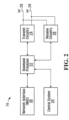
- FIG. 2 depicts an example of a base station 14.
- Base station 14 generally includes a control system 20, a baseband processor 22, transmit circuitry 24, receive circuitry 26, antennas 28, and a network interface 30.
- the receive circuitry 26 receives radio frequency signals bearing information from one or more remote transmitters provided by mobile terminals 16 (illustrated in FIG. 3 ) and relay stations 15 (illustrated in FIG. 4 ).
- a low noise amplifier and a filter may cooperate to amplify and remove broadband interference from the signal for processing.
- Downconversion and digitization circuitry (not shown) will then downconvert the filtered, received signal to an intermediate or baseband frequency signal, which is then digitized into one or more digital streams.
- the baseband processor 22 processes the digitized received signal to extract the information or data bits conveyed in the received signal. This processing typically comprises demodulation, decoding, and error correction operations. As such, the baseband processor 22 is generally implemented in one or more digital signal processors (DSPs) or application-specific integrated circuits (ASICs).
- DSPs digital signal processors
- ASICs application-specific integrated circuits
- baseband processor 22 receives digitized data, which may represent voice, data, or control information, from the network interface 30 under the control of control system 20, and encodes the data for transmission.
- the encoded data is output to the transmit circuitry 24, where it is modulated by one or more carrier signals having a desired transmit frequency or frequencies.
- a power amplifier (not shown) will amplify the modulated carrier signals to a level appropriate for transmission, and deliver the modulated carrier signals to the antennas 28 through a matching network (not shown). Modulation and processing details are described in greater detail below.
- FIG. 3 illustrates an example of a mobile terminal 16.
- the mobile terminal 16 will include a control system 32, a baseband processor 34, transmit circuitry 36, receive circuitry 38, antennas 40, and user interface circuitry 42.
- the receive circuitry 38 receives radio frequency signals bearing information from one or more base stations 14 and relays 15.
- a low noise amplifier and a filter may cooperate to amplify and remove broadband interference from the signal for processing.
- Downconversion and digitization circuitry (not shown) will then downconvert the filtered, received signal to an intermediate or baseband frequency signal, which is then digitized into one or more digital streams.
- Baseband processor 34 processes the digitized received signal to extract the information or data bits conveyed in the received signal. This processing typically comprises demodulation, decoding, and error correction operations.
- the baseband processor 34 is generally implemented in one or more digital signal processors (DSPs) and application specific integrated circuits (ASICs).
- DSPs digital signal processors
- ASICs application specific integrated circuits
- baseband processor 34 receives digitized data, which may represent voice, video, data, or control information, from the control system 32, which it encodes for transmission.
- the encoded data is output to the transmit circuitry 36, where it is used by a modulator to modulate one or more carrier signals that is at a desired transmit frequency or frequencies.
- a power amplifier (not shown) will amplify the modulated carrier signals to a level appropriate for transmission, and deliver the modulated carrier signal to the antennas 40 through a matching network (not shown).
- Various modulation and processing techniques available to those skilled in the art are used for signal transmission between the mobile terminal and the base station, either directly or via the relay station.
- the transmission band is divided into multiple, orthogonal carrier waves. Each carrier wave is modulated according to the digital data to be transmitted. Because OFDM divides the transmission band into multiple carriers, the bandwidth per carrier decreases and the modulation time per carrier increases. Since the multiple carriers are transmitted in parallel, the transmission rate for the digital data, or symbols, on any given carrier is lower than when a single carrier is used.
- OFDM modulation utilizes the performance of an Inverse Fast Fourier Transform (IFFT) on the information to be transmitted.
- FFT Fast Fourier Transform
- the IFFT and FFT are provided by digital signal processing carrying out an Inverse Discrete Fourier Transform (IDFT) and Discrete Fourier Transform (DFT), respectively.
- IDFT Inverse Discrete Fourier Transform
- DFT Discrete Fourier Transform
- the characterizing feature of OFDM modulation is that orthogonal carrier waves are generated for multiple bands within a transmission channel.
- the modulated signals are digital signals having a relatively low transmission rate and capable of staying within their respective bands.
- the individual carrier waves are not modulated directly by the digital signals. Instead, all carrier waves are modulated at once by IFFT processing.
- OFDM is preferably used for at least downlink transmission from the base stations 14 to the mobile terminals 16.
- the respective antennas can be used for reception and transmission using appropriate duplexers or switches and are so labelled only for clarity.
- OFDM is preferably used for downlink transmission from the base stations 14 to the relays 15 and from relay stations 15 to the mobile terminals 16.
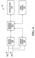
- FIG. 4 illustrates an example relay station 15.
- the relay station 15 includes a control system 132, a baseband processor 134, transmit circuitry 136, receive circuitry 138, antennas 130, and relay circuitry 142.
- the relay circuitry 142 enables the relay 14 to assist in communications between a base station 16 and mobile terminals 16.
- the receive circuitry 138 receives radio frequency signals bearing information from one or more base stations 14 and mobile terminals 16.
- a low noise amplifier and a filter may cooperate to amplify and remove broadband interference from the signal for processing.
- Downconversion and digitization circuitry (not shown) will then downconvert the filtered, received signal to an intermediate or baseband frequency signal, which is then digitized into one or more digital streams.
- Baseband processor 134 processes the digitized received signal to extract the information or data bits conveyed in the received signal. This processing typically comprises demodulation, decoding, and error correction operations.
- Baseband processor 134 is generally implemented in one or more digital signal processors (DSPs) and application specific integrated circuits (ASICs).
- DSPs digital signal processors
- ASICs application specific integrated circuits
- baseband processor 134 receives digitized data, which may represent voice, video, data, or control information, from control system 132, which it encodes for transmission.
- the encoded data is output to the transmit circuitry 136, where it is used by a modulator to modulate one or more carrier signals that is at a desired transmit frequency or frequencies.
- a power amplifier (not shown) will amplify the modulated carrier signals to a level appropriate for transmission, and deliver the modulated carrier signal to the antennas 130 through a matching network (not shown).
- Various modulation and processing techniques available to those skilled in the art are used for signal transmission between the mobile terminal and the base station, either directly or indirectly via a relay station, as described above.
- base station controller 10 will send data to be transmitted to various mobile terminals 16 to base station 14, either directly or with the assistance of a relay station 15.
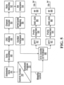
- Base station 14 may use the channel quality indicators (CQIs) associated with the mobile terminals to schedule the data for transmission as well as select appropriate coding and modulation for transmitting the scheduled data.
- the CQIs may be directly from the mobile terminals 16 or determined at the base station 14 based on information provided by the mobile terminals 16. In either case, the CQI for each mobile terminal 16 is a function of the degree to which the channel amplitude (or response) varies across the OFDM frequency band.
- Scheduled data 44 which is a stream of bits, is scrambled in a manner reducing the peak-to-average power ratio associated with the data using data scrambling logic 46.
- a cyclic redundancy check (CRC) for the scrambled data is determined and appended to the scrambled data using CRC adding logic 48.
- channel coding is performed using channel encoder logic 50 to effectively add redundancy to the data to facilitate recovery and error correction at the mobile terminal 16. Again, the channel coding for a particular mobile terminal 16 is based on the CQI.
- the channel encoder logic 50 uses known Turbo encoding techniques.
- the encoded data is then processed by rate matching logic 52 to compensate for the data expansion associated with encoding.
- Bit interleaver logic 54 systematically reorders the bits in the encoded data to minimize the loss of consecutive data bits.
- the resultant data bits are systematically mapped into corresponding symbols depending on the chosen baseband modulation by mapping logic 56.
- mapping logic 56 Preferably, Quadrature Amplitude Modulation (QAM) or Quadrature Phase Shift Key (QPSK) modulation is used.
- QAM Quadrature Amplitude Modulation
- QPSK Quadrature Phase Shift Key
- the degree of modulation is preferably chosen based on the CQI for the particular mobile terminal.
- the symbols may be systematically reordered to further bolster the immunity of the transmitted signal to periodic data loss caused by frequency selective fading using symbol interleaver logic 58.
- STC encoder logic 60 which modifies the symbols in a fashion making the transmitted signals more resistant to interference and more readily decoded at a mobile terminal 16.
- the STC encoder logic 60 will process the incoming symbols and provide "n" outputs corresponding to the number of transmit antennas 28 for the base station 14.
- the control system 20 and/or baseband processor 22 as described above with reference to FIG. 5 will provide a mapping control signal to control STC encoding.
- the symbols for the "n" outputs are representative of the data to be transmitted and capable of being recovered by the mobile terminal 16.
- each of the symbol streams output by the SIC encoder logic 60 is sent to a corresponding IFFT processor 62, illustrated separately for ease of understanding.
- the IFFT processors 62 will preferably operate on the respective symbols to provide an inverse Fourier Transform.
- the output of the TUFT processors 62 provides symbols in the time domain. The time domain symbols are grouped into frames, which are associated with a prefix by prefix insertion logic 64.
- Each of the resultant signals is up-converted in the digital domain to an intermediate frequency and converted to an analog signal via the corresponding digital up-conversion (DUG) and digital-to-analog (DIA) conversion circuitry 66 .
- the resultant (analog) signals are then simultaneously modulated at the desired RF frequency, amplified, and transmitted via the RF circuitry 68 and antennas 28.
- pilot signals known by the intended mobile terminal 16 are scattered among the sub-carriers. The mobile terminal 16, which is discussed in detail below, will use the pilot signals for channel estimation.
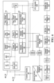
- FIG. 6 illustrates reception of the transmitted signals by a mobile terminal 16, either directly from base station 14 or with the assistance of relay 15.
- the respective signals are demodulated and amplified by corresponding RF circuitry 70.
- Analog-to-digital (AID) converter and down-conversion circuitry 72 digitizes and downconverts the analog signal for digital processing.
- the resultant digitized signal may be used by automatic gain control circuitry (AGC) 74 to control the gain of the amplifiers in the RF circuitry 70 based on the received signal level.
- AGC automatic gain control circuitry
- the digitized signal is provided to synchronization logic 76, which includes coarse synchronization logic 78, which buffers several OFDM symbols and calculates an auto-correlation between the two successive OFDM symbols.
- a resultant time index corresponding to the maximum of the correlation result determines a fine synchronization search window, which is used by fine synchronization logic 80 to determine a precise framing starting position based on the headers.
- the output of the fine synchronization logic 80 facilitates frame acquisition by frame alignment logic 84. Proper framing alignment is important so that subsequent PET processing provides an accurate conversion from the time domain to the frequency domain.
- the fine synchronization algorithm is based on the correlation between the received pilot signals carried by the headers and a local copy of the known pilot data.
- the synchronization logic 76 includes frequency offset and clock estimation logic 82, which is based on the headers to help estimate such effects on the transmitted signal and provide those estimations to the correction logic 88 to properly process OFDM symbols.
- the OFDM symbols in the time domain are ready for conversion to the frequency domain using EFT processing logic 90.
- the results are frequency domain symbols, which are sent to processing logic 92.
- the processing logic 92 extracts the scattered pilot signal using scattered pilot extraction logic 94, determines a channel estimate based on the- extracted pilot signal using channel estimation logic 96, and provides channel responses for all sub-carriers using channel reconstruction logic 98.
- the pilot signal is essentially multiple pilot symbols that are scattered among the data symbols throughout the OFDM sub-carriers in a known pattern in both time and frequency.
- the processing logic compares the received pilot symbols with the pilot symbols that are expected in certain sub-carriers at certain times to determine a channel response for the sub-carriers in which pilot symbols were transmitted.
- the results are interpolated to estimate a channel response for most, if not all, of the remaining sub-carriers for which pilot symbols were not provided.
- the actual and interpolated channel responses are used to estimate an overall channel response, which includes the channel responses for most, if not all, of the sub-carriers in the OFDM channel.
- the frequency domain symbols and channel reconstruction information which are derived from the channel responses for each receive path are provided to an STC decoder 100, which provides STC decoding on both received paths to recover the transmitted symbols.
- the channel reconstruction information provides equalization information to STC decoder 100 sufficient to remove the effects of the transmission channel when processing the respective frequency domain symbols.
- the relay station could act as another base station or as a terminal in the context of this invention.
- the recovered symbols are placed back in order using symbol de-interleaver logic 102, which corresponds to the symbol interleaver logic 58 of the transmitter.
- the de-interleaved symbols are then demodulated or de-mapped to a corresponding bitstream using dc-mapping logic 104.
- the bits are then de-interleaved using bit de-interleaver logic 106, which corresponds to the bit interleaver logic 54 of the transmitter architecture.
- the dc-interleaved bits are then processed by rate dc-matching logic 108 and presented to channel decoder logic 110 to recover the initially scrambled data and the CRC checksum.
- CRC logic 112 removes the CRC checksum, checks the scrambled data in traditional fashion, and provides it to the de-scrambling logic 114 for de-scrambling using the known base station de-scrambling code to recover the originally transmitted data 116.
- a CQI or at least information sufficient to create a CQI at the base station 14 is determined and transmitted to the base station 14
- the CQI may be a function of the carrier-to-interference ratio (CIR), as well as the degree to which the channel response varies across the various sub-carriers in the OFDM frequency band.
- CIR carrier-to-interference ratio
- the channel gain for each sub-carrier in the OFDM frequency band being used to transmit information is compared relative to one another to determine the degree to which the channel gain varies across the OFDM frequency band.
- numerous techniques are available to measure the degree of variation, one technique is to calculate the standard deviation of the channel gain for each sub-carrier throughout the OFDM frequency band being used to transmit data.
- FIGS. 1 to 6 provide one specific example of a communication system that could be used to implement embodiments of the application. It is to be understood that embodiments can be implemented with communications systems having architectures that are different than the specific example, but that operate in a manner consistent with the implementation of the embodiments as described herein.
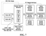
- FIG. 7 is a block diagram illustrating a logical representation of an overall network architecture 700 that might be used to implement some embodiments of the present application.
- overall network architecture 700 consists of the following functional entities: mobile stations (MS) 702, access service networks (ASN) 706 comprising base stations (BS) 704 and ASN-gateways (ASN-GW) 705, and a number of connectivity service networks (CSN) 708.
- Network architecture 700 may be based on the framework defined in WiMAX Network Architecture (The WiMAX Forum Network Architecture Stage 2 - 3: Release 1, Version 1.2, the entire contents of which are incorporated by reference herein).
- ASN 706 may be IEEE 802.16m/e compliant.
- ASN 706 provides a complete set of network functions needed to provide radio access to an IEEE 802.16e/m subscriber.
- ASN 706 provides at least the following functions: IEEE 802.16e/m Layer-1 (L1) and Layer-2 (L2) connectivity with IEEE 802.16e/m MS; transfer of AAA messages to IEEE 802.16e/m subscriber's Home Network Service Provider (H-NSP) for authentication, authorization and session accounting for subscriber sessions; network discovery and selection of the IEEE 802.16e/m subscriber's preferred NSP; relay functionality for establishing Layer-3 (L3) connectivity with an IEEE 802.16e/m MS (i.e. IP address allocation); and Radio Resource Management.
- L1 Layer-1
- L2 Layer-2
- H-NSP Home Network Service Provider
- ASN 706 further supports the following functions: ASN anchored mobility; CSN anchored mobility; paging; and ASN-CSN tunnelling.
- Each CSN 708 is a set of network functions that provide IP connectivity services to IEEE 802.16e/m subscriber(s).
- a given ASN 706 may be shared by more than one CSN 708.
- a CSN 708 may provide the following functions: MS IP address and endpoint parameter allocation for user sessions; Internet access; AAA proxy or server; policy and Admission Control based on user subscription profiles; ASN-CSN tunneling support; IEEE 802.16e/m subscriber billing and inter-operator settlement; inter-CSN tunneling for roaming; and inter-ASN mobility.
- a CSN 708 may further comprise network elements (not shown) such as routers, AAA proxy/servers, user databases, Interworking gateway MSs.
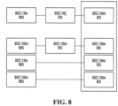
- relay stations (RS) 802 may be deployed in the network to provide improved coverage and/or capacity.
- RSs 802 When RSs 802 are present, communications between a BS 704 and a MS 702 can occur directly or via a RS 802.
- IEEE 802.16j defines two relay station types according to the number of carriers they can support during relaying:
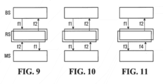
- TDD operation that is, the same frequency is being used for both DL and UL communication on any given interface.
- a RS may use the same carrier f1 for its DL transmission that its superordinate station uses for its DL, and the same carrier f2 for its UL transmission that its superordinate station uses for its UL.
- This option requires two carrier frequencies, and as described in more detail below the frame structure may have to be split into access and relay zones.
- FIG.9 illustrates the case where the relay is half-duplex (i.e., it does not receive and transmit simultaneously on a given interface) and the relay operation occurs in a time division fashion.
- FIG. 10 illustrates the case where the relay is full-duplex (i.e., it receives and transmits simultaneously at the same interface).
- a RS may use a different DL (UL) frequency from the DL (UL) frequency of its super ordinate station. Note that this option requires 4 carriers (2 for odd hops and 2 for even hops). FIG. 11 depicts this case.
- FIGS. 10 and 11 are similar to each other except that a relay that can operate according to FIG. 10 may require more complex antenna deployment and interference cancellation circuitry for receiving and transmitting simultaneously at the same time at the frequencies. From configuration point of view, they can be treated as being the same.
- the relay system depicted in FIG. 9 is more practical in terms of hardware implementation and design, and in addition, the operation suits well to the H-FDD operation already defined in the IEEE 802.16e/Rev2 standard.
- both DL and UL frames are split into 2 intervals T1 and T2, one for Group 1 MSs/SSs and one for Group 2 MSs/SSs.
- T1 (T2) interval Group 1 (Group 2) MSs/SSs receive the DL signals from the BS
- T2 (T1) interval Group 1 (Group 2) MSs/SSs transmit their UL signals to the BS.
- this frame structure may be modified for use in a multi-hop relay network, for example, by inserting the optional relay amble (R-amble), replacing FCH/DL-MAP with R-FCH/R-MAP, etc.
- R-amble optional relay amble
- DCD DL Channel Descriptor
- UCD UL Channel Descriptor
- DL-MAP DL-MAP
- an MS first synchronizes to an available channel and reads DL-MAP1 ( FIG. 13 ) to receive DCD/UCD. Initially, MS performs its ranging operation as part of Group 1. There may be one or two DCD/UCD. If there is one DCD/UCD and the same type/length/value (TLV) is repeated twice, the first one belongs to user Group 1 and the second belongs to user Group 2.
- TLV type/length/value
- MS receives the length of T1 (T2) interval in the current (next) frame from DL-MAP 1 (DL MAP 2), and the UL carrier frequency from UCD.
- DCD/UCD provides parameters such as DL_gap size, DL_residue gap size and its location, TTGs and RTGs, etc. so that MS/SS can locate exactly the DL and UL intervals within the frame.
- MS performs initial ranging assuming itself in Group 1.
- IE Group switch Information Element
- DL MAP refers to allocations in the current frame while UL MAP refers to a region in the next frame.
- the DL MAP 1 or DL MAP 2 refers to a region in the current frame, while UL MAP 1 refers to the next frame, and UL MAP 2 refers to the next-next frame.
- BS can transmit FDD Paired Allocation IE to schedule the full-duplex MSs to all H-FDD resources available.
- the FDD Paired Allocation IE contains UL MAP IEs that refer to allocations in the other UL region. This IE may also contain a UL Zone Switch IE and a UL Allocation Start IE, in which case those IEs refer to configuration related to the other UL allocation region.
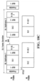
- the FDD frame structure shown in FIG. 13 may be modified to support multihop relaying.
- the DL1, DL2, UL1 and UL2 subframes may each be divided into two zones in order to support BS-RS and RS-MS communications in addition to BS-MS communications.
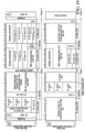
- the frame structure of FIG. 18A supports a coordinated transmission arrangement of two groups of H-FDD stations (Group-1 and Group-2) that share the frame at distinct partitions of the frame.
- T-RS transparent RS
- the DL1 and DL2 subframes may each be divided into an access zone and a transparent zone
- the UL1 and UL2 subframes may each be divided into an access zone and a relay zone, as shown in FIG. 18B .
- a T-RS can be assigned to one of Group-1 and Group-2 in the same way as a MS is assigned.
- MR-BS can simultaneously assign multiple T-RSs to each Group since T-RSs can be treated as if they are MSs
- a T-RS assigned to Group 1 (Group 2) can relay data in the DL1/UL1 (DL2/UL2) regions. For simplicity, all RSs may be assigned to the same Group so that the FCH/MAP for that Group may contain only optional FCH/R-MAP.
- the DL1, DL2, UL1 and UL2 subframes may each be divided into an access zone and a relay zone, as shown in FIG. 18C .
- a capable NT-RS in Group 1 (Group 2) can use the entire UL zone except for UL 1 (UL 2).
- the R-link Channel Description (RCD) MAC message can be employed to signal the access and relay zones.
- the access zones may be contiguous and fall within one of the subframes of the H-FDD frame, while the relay zones may be contiguous and fall within the other subframe.
- the FCH/MAP and R-FCH/RMAP can be transmitted in the first tx access zone and relay zone, respectively.
- the RS may obtain the UL carrier from the UCD during network entry.
- the same carrier frequencies used at the first hop may be used at other hops.
- the second carrier frequency signalled in the RS Config CMD message can refer to the DL carrier in FDD mode.
- FDD mode an additional TLV may be signalled to configure the UL carrier for RS to use in communicating with subordinate stations.
- all of the half-duplex MSs/SSs may be set as Group 1 users, and all of the RSs may be set as Group 2 users (or vice versa) in FDD mode.
- An RS can still operate in full-duplex mode, e.g., it may be allocated resources at all available H-FDD resources via FDD Paired Allocation IE.
- a transparent RS can monitor both DL MAP 1 and DL MAP 2, and perform relaying according the forwarding rules it has. In systems where all RSs are transparent, MSs/SSs can be switched between groups.
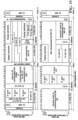
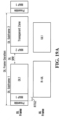
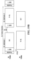
- FIGS. 19A and 19B illustrate alternative frame configurations for T-RS and NT-RS operation, respectively, wherein the second subframe of the H-FDD frame structure is used as the transparent zone or the relay zone, as the case may be. That is, rather than divide DL1, DL2, UL1 and UL2 into zones, relays are assigned to only one Group (say, Group 2; i.e. DL2 and UL2, as shown in FIGS. 19A and 19B ). For non-transparent RS operation, advantage is taken off the MAP2, since the relay would need its own (R-MAP).
- TDD fits better to the asymmetric characteristics of DL-UL transmissions.
- the conventional H-FDD frame shown in FIG. 13 assumes only two groups of users, leading to limited flexibility on varying the DL-UL ratio and resulting in about two OFDM symbols being wasted due to the RTG/TRG and/or DL_gap/UL_gap requirement.
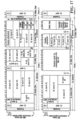
- FIG. 20 illustrates an H-FDD frame configuration having three user group regions.
- the DL_gaplUL_gap requirement may be eliminated, and the RTGs for MS Groups 1 and 3 may be absorbed by their respective radio idle states.
- TRG instead of RTG, takes a longer time, by reordering the UL group transmission the TRG for the three MS Groups can be absorbed instead. Flexibility is also gained in varying the DL-UL ratio since radio idle state can be explored.
- FIG. 21 illustrates a three-hop case for the H-FDD frame configuration of FIG. 20 . As shown, given more hops more flexibility can be expected, however a higher number of groups of MSs are required.
Landscapes
- Engineering & Computer Science (AREA)
- Computer Networks & Wireless Communication (AREA)
- Signal Processing (AREA)
- Mobile Radio Communication Systems (AREA)
- Radio Relay Systems (AREA)
- Stabilization Of Oscillater, Synchronisation, Frequency Synthesizers (AREA)
Applications Claiming Priority (3)
| Application Number | Priority Date | Filing Date | Title |
|---|---|---|---|
| US23951409P | 2009-09-03 | 2009-09-03 | |
| PCT/CA2010/001351 WO2011026224A1 (en) | 2009-09-03 | 2010-09-03 | Frequency division duplexing in multihop relay networks |
| EP10813196.2A EP2474107A4 (en) | 2009-09-03 | 2010-09-03 | FREQUENCY DUPLEXING IN MULTIHOP RELAY NETWORKS |
Related Parent Applications (1)
| Application Number | Title | Priority Date | Filing Date |
|---|---|---|---|
| EP10813196.2A Division EP2474107A4 (en) | 2009-09-03 | 2010-09-03 | FREQUENCY DUPLEXING IN MULTIHOP RELAY NETWORKS |
Publications (1)
| Publication Number | Publication Date |
|---|---|
| EP4164140A1 true EP4164140A1 (en) | 2023-04-12 |
Family
ID=43648804
Family Applications (2)
| Application Number | Title | Priority Date | Filing Date |
|---|---|---|---|
| EP10813196.2A Ceased EP2474107A4 (en) | 2009-09-03 | 2010-09-03 | FREQUENCY DUPLEXING IN MULTIHOP RELAY NETWORKS |
| EP22196827.4A Withdrawn EP4164140A1 (en) | 2009-09-03 | 2010-09-03 | Frequency division duplexing in multihop relay networks |
Family Applications Before (1)
| Application Number | Title | Priority Date | Filing Date |
|---|---|---|---|
| EP10813196.2A Ceased EP2474107A4 (en) | 2009-09-03 | 2010-09-03 | FREQUENCY DUPLEXING IN MULTIHOP RELAY NETWORKS |
Country Status (8)
| Country | Link |
|---|---|
| EP (2) | EP2474107A4 (cg-RX-API-DMAC7.html) |
| JP (1) | JP2013504223A (cg-RX-API-DMAC7.html) |
| CN (1) | CN102792609A (cg-RX-API-DMAC7.html) |
| BR (1) | BR112012004801A2 (cg-RX-API-DMAC7.html) |
| CA (1) | CA2773052C (cg-RX-API-DMAC7.html) |
| IN (1) | IN2012DN02001A (cg-RX-API-DMAC7.html) |
| RU (1) | RU2012112888A (cg-RX-API-DMAC7.html) |
| WO (1) | WO2011026224A1 (cg-RX-API-DMAC7.html) |
Families Citing this family (4)
| Publication number | Priority date | Publication date | Assignee | Title |
|---|---|---|---|---|
| JP5187909B2 (ja) * | 2009-10-05 | 2013-04-24 | 株式会社エヌ・ティ・ティ・ドコモ | 移動通信方法及びリレーノード |
| US9014110B2 (en) * | 2011-07-18 | 2015-04-21 | Qualcomm Incorporated | Enabling half-duplex operation |
| JP2016524856A (ja) * | 2013-05-22 | 2016-08-18 | エルジー エレクトロニクス インコーポレイティド | 全二重無線方式を支援する無線接続システムにおいて適用される全二重無線領域の構造、これを割り当てる方法及び装置 |
| CN106937365B (zh) * | 2015-12-31 | 2018-06-26 | 深圳友讯达科技股份有限公司 | 无线自组网节点通信方法及节点 |
Family Cites Families (1)
| Publication number | Priority date | Publication date | Assignee | Title |
|---|---|---|---|---|
| US20100278123A1 (en) * | 2007-12-10 | 2010-11-04 | Nortel Networks Limited | Wireless communication frame structure and apparatus |
-
2010
- 2010-09-03 IN IN2001DEN2012 patent/IN2012DN02001A/en unknown
- 2010-09-03 JP JP2012527164A patent/JP2013504223A/ja active Pending
- 2010-09-03 CA CA2773052A patent/CA2773052C/en active Active
- 2010-09-03 EP EP10813196.2A patent/EP2474107A4/en not_active Ceased
- 2010-09-03 BR BR112012004801A patent/BR112012004801A2/pt not_active Application Discontinuation
- 2010-09-03 CN CN2010800496505A patent/CN102792609A/zh active Pending
- 2010-09-03 WO PCT/CA2010/001351 patent/WO2011026224A1/en not_active Ceased
- 2010-09-03 RU RU2012112888/07A patent/RU2012112888A/ru not_active Application Discontinuation
- 2010-09-03 EP EP22196827.4A patent/EP4164140A1/en not_active Withdrawn
Non-Patent Citations (2)
| Title |
|---|
| "IEEE Standard for Local and metropolitan area networks Part 16: Air Interface for Broadband Wireless Access Systems Amendment 1: Multihop Relay Specification;IEEE Std 802.16j-2009 (Amendment to IEEE Std 802.16-2009)", IEEE STANDARD, IEEE, PISCATAWAY, NJ, USA, 12 June 2009 (2009-06-12), pages 1 - 290, XP068045638, ISBN: 978-0-7381-5922-5 * |
| RAINER SCHOENEN ET AL: "Concurrent Operation of Half- and Full-Duplex Terminals in Future Multi-Hop FDD Based Cellular Networks", 2008 4TH INTERNATIONAL CONFERENCE ON WIRELESS COMMUNICATIONS, NETWORKING AND MOBILE COMPUTING : DALIAN, CHINA, 12 - 17 OCTOBER 2008, PISCATAWAY, NJ : IEEE, US, 12 October 2008 (2008-10-12), pages 1 - 7, XP008152657 * |
Also Published As
| Publication number | Publication date |
|---|---|
| RU2012112888A (ru) | 2013-10-20 |
| CA2773052C (en) | 2018-05-22 |
| EP2474107A1 (en) | 2012-07-11 |
| BR112012004801A2 (pt) | 2017-05-30 |
| EP2474107A4 (en) | 2016-05-25 |
| JP2013504223A (ja) | 2013-02-04 |
| IN2012DN02001A (cg-RX-API-DMAC7.html) | 2015-07-24 |
| WO2011026224A1 (en) | 2011-03-10 |
| CA2773052A1 (en) | 2011-03-10 |
| CN102792609A (zh) | 2012-11-21 |
Similar Documents
| Publication | Publication Date | Title |
|---|---|---|
| US8576753B2 (en) | System and method for wireless relay frame structure, protocol, and operation | |
| US8929303B2 (en) | Control and data channels for advanced relay operation | |
| US8547895B2 (en) | Method and apparatus for transmitting and receiving signal in relay station | |
| US9014067B2 (en) | Method and apparatus for configuring frame in wireless communication system including relay station | |
| US20080165881A1 (en) | Method for Accessing Channels in OFDMA Mobile Multihop Relay Networks | |
| US8718010B2 (en) | Method for transmitting frame in wireless communication system including relay station | |
| US9397775B2 (en) | Frequency division duplexing and half duplex frequency division duplexing in multihop relay networks | |
| CN102204136B (zh) | 适用于下行链路中的用户设备的中继技术 | |
| US9083396B2 (en) | OFDMA-based operation of a wireless subscriber terminal in a plurality of cells | |
| CA2773052C (en) | Frequency division duplexing in multihop relay networks | |
| KR101749110B1 (ko) | 무선 통신 시스템에서 소정의 프레임 구조를 이용하여 신호를 송수신하는 장치 및 방법 | |
| US8767613B2 (en) | Method and apparatus for allocating wireless resource in wireless communication system including relay station | |
| US8514765B1 (en) | Dynamic zoning changes in multi-hop relaying systems | |
| US20090252081A1 (en) | Apparatus and method for supporting various systems in a multihop relay broadband wireless communication system | |
| KR101636581B1 (ko) | 중계국의 신호 송수신 방법 및 장치 |
Legal Events
| Date | Code | Title | Description |
|---|---|---|---|
| PUAI | Public reference made under article 153(3) epc to a published international application that has entered the european phase |
Free format text: ORIGINAL CODE: 0009012 |
|
| STAA | Information on the status of an ep patent application or granted ep patent |
Free format text: STATUS: THE APPLICATION HAS BEEN PUBLISHED |
|
| AC | Divisional application: reference to earlier application |
Ref document number: 2474107 Country of ref document: EP Kind code of ref document: P |
|
| AK | Designated contracting states |
Kind code of ref document: A1 Designated state(s): AL AT BE BG CH CY CZ DE DK EE ES FI FR GB GR HR HU IE IS IT LI LT LU LV MC MK MT NL NO PL PT RO SE SI SK SM TR |
|
| STAA | Information on the status of an ep patent application or granted ep patent |
Free format text: STATUS: THE APPLICATION IS DEEMED TO BE WITHDRAWN |
|
| 18D | Application deemed to be withdrawn |
Effective date: 20231013 |