EP4164137B1 - Berechnung von strahlformungsparametern - Google Patents
Berechnung von strahlformungsparametern Download PDFInfo
- Publication number
- EP4164137B1 EP4164137B1 EP22198224.2A EP22198224A EP4164137B1 EP 4164137 B1 EP4164137 B1 EP 4164137B1 EP 22198224 A EP22198224 A EP 22198224A EP 4164137 B1 EP4164137 B1 EP 4164137B1
- Authority
- EP
- European Patent Office
- Prior art keywords
- eigenvector
- estimate
- computing
- eigenvector estimate
- initial
- Prior art date
- Legal status (The legal status is an assumption and is not a legal conclusion. Google has not performed a legal analysis and makes no representation as to the accuracy of the status listed.)
- Active
Links
Images


Classifications
-
- H—ELECTRICITY
- H04—ELECTRIC COMMUNICATION TECHNIQUE
- H04B—TRANSMISSION
- H04B7/00—Radio transmission systems, i.e. using radiation field
- H04B7/02—Diversity systems; Multi-antenna system, i.e. transmission or reception using multiple antennas
- H04B7/04—Diversity systems; Multi-antenna system, i.e. transmission or reception using multiple antennas using two or more spaced independent antennas
- H04B7/0413—MIMO systems
- H04B7/0456—Selection of precoding matrices or codebooks, e.g. using matrices antenna weighting
-
- H—ELECTRICITY
- H04—ELECTRIC COMMUNICATION TECHNIQUE
- H04B—TRANSMISSION
- H04B7/00—Radio transmission systems, i.e. using radiation field
- H04B7/02—Diversity systems; Multi-antenna system, i.e. transmission or reception using multiple antennas
- H04B7/04—Diversity systems; Multi-antenna system, i.e. transmission or reception using multiple antennas using two or more spaced independent antennas
- H04B7/0404—Diversity systems; Multi-antenna system, i.e. transmission or reception using multiple antennas using two or more spaced independent antennas the mobile station comprising multiple antennas, e.g. to provide uplink diversity
-
- H—ELECTRICITY
- H04—ELECTRIC COMMUNICATION TECHNIQUE
- H04B—TRANSMISSION
- H04B7/00—Radio transmission systems, i.e. using radiation field
- H04B7/02—Diversity systems; Multi-antenna system, i.e. transmission or reception using multiple antennas
- H04B7/04—Diversity systems; Multi-antenna system, i.e. transmission or reception using multiple antennas using two or more spaced independent antennas
- H04B7/06—Diversity systems; Multi-antenna system, i.e. transmission or reception using multiple antennas using two or more spaced independent antennas at the transmitting station
- H04B7/0613—Diversity systems; Multi-antenna system, i.e. transmission or reception using multiple antennas using two or more spaced independent antennas at the transmitting station using simultaneous transmission
- H04B7/0615—Diversity systems; Multi-antenna system, i.e. transmission or reception using multiple antennas using two or more spaced independent antennas at the transmitting station using simultaneous transmission of weighted versions of same signal
- H04B7/0617—Diversity systems; Multi-antenna system, i.e. transmission or reception using multiple antennas using two or more spaced independent antennas at the transmitting station using simultaneous transmission of weighted versions of same signal for beam forming
-
- H—ELECTRICITY
- H04—ELECTRIC COMMUNICATION TECHNIQUE
- H04L—TRANSMISSION OF DIGITAL INFORMATION, e.g. TELEGRAPHIC COMMUNICATION
- H04L25/00—Baseband systems
- H04L25/02—Details ; arrangements for supplying electrical power along data transmission lines
- H04L25/0202—Channel estimation
- H04L25/021—Estimation of channel covariance
-
- H—ELECTRICITY
- H04—ELECTRIC COMMUNICATION TECHNIQUE
- H04L—TRANSMISSION OF DIGITAL INFORMATION, e.g. TELEGRAPHIC COMMUNICATION
- H04L25/00—Baseband systems
- H04L25/02—Details ; arrangements for supplying electrical power along data transmission lines
- H04L25/03—Shaping networks in transmitter or receiver, e.g. adaptive shaping networks
- H04L25/03891—Spatial equalizers
- H04L25/03961—Spatial equalizers design criteria
- H04L25/03968—Spatial equalizers design criteria mean-square error [MSE]
-
- Y—GENERAL TAGGING OF NEW TECHNOLOGICAL DEVELOPMENTS; GENERAL TAGGING OF CROSS-SECTIONAL TECHNOLOGIES SPANNING OVER SEVERAL SECTIONS OF THE IPC; TECHNICAL SUBJECTS COVERED BY FORMER USPC CROSS-REFERENCE ART COLLECTIONS [XRACs] AND DIGESTS
- Y02—TECHNOLOGIES OR APPLICATIONS FOR MITIGATION OR ADAPTATION AGAINST CLIMATE CHANGE
- Y02D—CLIMATE CHANGE MITIGATION TECHNOLOGIES IN INFORMATION AND COMMUNICATION TECHNOLOGIES [ICT], I.E. INFORMATION AND COMMUNICATION TECHNOLOGIES AIMING AT THE REDUCTION OF THEIR OWN ENERGY USE
- Y02D30/00—Reducing energy consumption in communication networks
- Y02D30/70—Reducing energy consumption in communication networks in wireless communication networks
Definitions
- the exemplary and non-limiting embodiments of the invention relate generally to communication systems.
- Embodiments of the invention relate especially to computing beamforming coefficients to realize spatial directivity towards a desired direction in wireless communications.
- Beamforming is a fundamental part of modern radio communications, e.g. modern cellular communication systems such as the fourth generation (long-term evolution, LTE) and the fifth generation (New Radio, NR) systems. Efficient estimation of eigen beams to be used in transmission and reception beamforming is crucial to implement power-efficient and highly performing radio products. This applies to both access node and terminal devices of radio systems.
- An eigenbeam can be understood as a directive beam focusing radio energy to a desired direction with desired amplification. Multiple eigenbeams may be computed to realize multiple spatially uncorrelated channels between a transmitter and receiver. Eigenvalue decomposition may be used to compute the eigenbeams. Efficient computation of the eigenbeams is an important factor.
- LAL C GODARA "Application of Antenna Arrays to Mobile Communications, Part II: Beam-Forming and Direct ion-of -Arrival Considerations ", PROCEEDINGS OF THE IEEE, IEEE. NEW YORK, US, vol. 85, no. 8,1 August 1997 (1997-08-01), pages 1195-1245, XP011043875
- an apparatus comprising means for performing: obtaining a channel covariance matrix representing a radio channel between the apparatus and another apparatus; obtaining an initial eigenvector estimate; computing an intermediate eigenvector estimate based on the channel covariance matrix and the initial eigenvector estimate; computing an error vector representing an error between the initial eigenvector estimate and the intermediate eigenvector estimate; computing a final eigenvector estimate based on the error vector and the intermediate eigenvector estimate; and determining beamforming coefficients based on the final eigenvector estimate and communicating with said another apparatus by using the beamforming coefficients.
- the means are configured to iterate obtaining the initial eigenvector estimate, computing the intermediate eigenvector estimate, computing the error vector, and computing the final eigenvector estimate, wherein said computing the final eigenvector estimate for an iteration comprises removing the error vector from the initial eigenvector estimate, the resulting eigenvector estimate serving as a new initial eigenvector estimate for a subsequent iteration or, after the last iteration, as an input to said determining the beamforming coefficients.
- the means are configured to compute at least two eigenvectors and wherein the number of iterations for computing the final eigenvector estimate is different for the at least two eigenvectors.
- the means are configured to: remove one or more components that are parallel to the final eigenvector estimate from the channel covariance matrix; and perform obtaining the initial eigenvector estimate, computing the intermediate eigenvector estimate, computing the error vector, computing the final eigenvector estimate, and determining the beamforming coefficients, for a further eigenvector of the channel covariance matrix from which the one or more components have been removed.
- the means are configured to obtain an error scaling factor, and to scale the error vector by the error scaling factor when computing the final eigenvector estimate.
- a value of the error scaling factor is changed between at least two consecutive iterations.
- the error scaling factor is based on a size of the channel covariance matrix.
- the error scaling factor is based on an index of the eigenvector, wherein a first error scaling factor based on a first index is greater than or equal to a second error scaling value based on a second index, wherein the second index is greater than the first index.
- the error scaling factor is between 0 and 1.
- computing the intermediate eigenvector estimate comprises normalizing the initial eigenvector estimate by a maximum element of the initial eigenvector estimate.
- the normalizing is based on a maximum real value of the initial eigenvector estimate and/or a maximum imaginary value of the initial eigenvector estimate.
- the means are configured to normalize the final eigenvector estimate to a norm of the final eigenvector estimate.
- a method comprising: obtaining a channel covariance matrix representing a radio channel between an apparatus and another apparatus; obtaining an initial eigenvector estimate for an eigenvector of the channel covariance matrix; computing an intermediate eigenvector estimate based on the channel matrix and the initial eigenvector estimate; computing an error vector representing an error between the initial eigenvector estimate and the intermediate eigenvector estimate; computing a final eigenvector estimate based on the error vector and the intermediate eigenvector estimate; and determining beamforming coefficients based on the final eigenvector estimate and communicating with said another apparatus by using the beamforming coefficients.
- a computer program comprising instructions for causing an apparatus to perform: obtaining a channel covariance matrix representing a radio channel between the apparatus and another apparatus; obtaining an initial eigenvector estimate for an eigenvector of the channel matrix; computing an intermediate eigenvector estimate based on the channel covariance matrix and the initial eigenvector estimate; computing an error vector representing an error between the initial eigenvector estimate and the intermediate eigenvector estimate; computing a final eigenvector estimate based on the error vector and the intermediate eigenvector estimate; and determining beamforming coefficients based on the final eigenvector estimate and communicating with said another apparatus by using the beamforming coefficients.
- Some embodiments of the present invention are applicable to a user terminal, a communication device, a base station, eNodeB, gNodeB, a distributed realisation of a base station, a network element of a communication system, a corresponding component, and/or to any communication system or any combination of different communication systems that support required functionality.
- UMTS universal mobile telecommunications system
- UTRAN wireless local area network
- WiFi wireless local area network
- WiMAX worldwide interoperability for microwave access
- Bluetooth ® personal communications services
- PCS personal communications services
- WCDMA wideband code division multiple access
- UWB ultra-wideband
- sensor networks sensor networks
- MANETs mobile ad-hoc networks
- IMS Internet Protocol multimedia subsystems
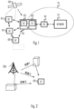
- Fig. 1 depicts examples of simplified system architectures only showing some elements and functional entities, all being logical units, whose implementation may differ from what is shown.
- the connections shown in Fig. 1 are logical connections; the actual physical connections may be different. It is apparent to a person skilled in the art that the system typically comprises also other functions and structures than those shown in Fig. 1 .
- Fig. 1 shows a part of an exemplifying radio access network.
- Fig. 1 shows devices 100 to 102.
- the devices 100 to 102 are configured to be in a wireless connection on one or more communication channels with a node 104.
- the node 104 is further connected to a core network 110.
- the node 104 may be an access node such as (e/g)NodeB serving devices in a cell.
- the node 104 may be a non-3GPP access node.
- the physical link from a device to a (e/g)NodeB is called uplink or reverse link and the physical link from the (e/g)NodeB to the device is called downlink or forward link.
- (e/g)NodeBs or their functionalities may be implemented by using any node, host, server or access point etc. entity suitable for such a usage.
- a communications system typically comprises more than one (e/g) NodeB in which case the (e/g)NodeBs may also be configured to communicate with one another over links, wired or wireless, designed for the purpose. These links may be used for signalling purposes.
- the (e/g)NodeB is a computing device configured to control the radio resources of communication system it is coupled to.
- the NodeB may also be referred to as a base station, an access point or any other type of interfacing device including a relay station capable of operating in a wireless environment.
- the (e/g)NodeB includes or is coupled to transceivers. From the transceivers of the (e/g)NodeB, a connection is provided to an antenna unit that establishes bi-directional radio links to devices.
- the antenna unit may comprise a plurality of antennas or antenna elements.
- the (e/g)NodeB is further connected to the core network 110 (CN or next generation core NGC). Depending on the deployed technology, the (e/g)NodeB is connected to a serving and packet data network gateway (S-GW +P-GW) or user plane function (UPF), for routing and forwarding user data packets and for providing connectivity of devices to one ore more external packet data networks, and to a mobile management entity (MME) or access mobility management function (AMF), for controlling access and mobility of the devices.
- S-GW +P-GW serving and packet data network gateway
- UPF user plane function
- MME mobile management entity
- AMF access mobility management function
- Exemplary embodiments of a device 100, 101, 102 are a subscriber unit, a user device, a user equipment (UE), a user terminal, a terminal device, a mobile station, a mobile device, etc.
- UE user equipment
- the device typically refers to a mobile or static device (e.g. a portable or non-portable computing device) that includes wireless mobile communication devices operating with or without an universal subscriber identification module (USIM), including, but not limited to, the following types of devices: mobile phone, smartphone, personal digital assistant (PDA), handset, device using a wireless modem (alarm or measurement device, etc.), laptop and/or touch screen computer, tablet, game console, notebook, and multimedia device.
- a device may also be a nearly exclusive uplink only device, of which an example is a camera or video camera loading images or video clips to a network.
- a device may also be a device having capability to operate in Internet of Things (IoT) network which is a scenario in which objects are provided with the ability to transfer data over a network without requiring human-to-human or human-to-computer interaction, e.g. to be used in smart power grids and connected vehicles.
- IoT Internet of Things
- the device may also utilise cloud.
- a device may comprise a user portable device with radio parts (such as a watch, earphones or eyeglasses) and the computation is carried out in the cloud.
- the device illustrates one type of an apparatus to which resources on the air interface are allocated and assigned, and thus any feature described herein with a device may be implemented with a corresponding apparatus, such as a relay node.
- a relay node is a layer 3 relay (self-backhauling relay) towards the base station.
- the device (or in some embodiments a layer 3 relay node) is configured to perform one or more of user equipment functionalities.
- CPS cyber-physical system
- ICT interconnected information and communications technology
- devices sensors, actuators, processors microcontrollers, etc.
- mobile cyber physical systems in which the physical system in question has inherent mobility, are a subcategory of cyber-physical systems. Examples of mobile physical systems include mobile robotics and electronics transported by humans or animals.
- apparatuses have been depicted as single entities, different units, processors and/or memory units (not all shown in Fig. 1 ) may be implemented.
- 5G enables using multiple input - multiple output (MIMO) antennas, many more base stations or nodes than the LTE (a so-called small cell concept), including macro sites operating in co-operation with smaller stations and employing a variety of radio technologies depending on service needs, use cases and/or spectrum available.
- 5G mobile communications supports a wide range of use cases and related applications including video streaming, augmented reality, different ways of data sharing and various forms of machine type applications (such as (massive) machine-type communications (mMTC), including vehicular safety, different sensors and real-time control.
- 5G is expected to have multiple radio interfaces, e.g. below 6GHz or above 24 GHz, cmWave and mmWave, and also being integrable with existing legacy radio access technologies, such as the LTE.
- Integration with the LTE may be implemented, at least in the early phase, as a system, where macro coverage is provided by the LTE and 5G radio interface access comes from small cells by aggregation to the LTE.
- 5G is planned to support both inter-RAT operability (such as LTE-5G) and inter-RI operability (inter-radio interface operability, such as below 6GHz - cmWave, 6 or above 24 GHz - cmWave and mmWave).
- inter-RAT operability such as LTE-5G
- inter-RI operability inter-radio interface operability, such as below 6GHz - cmWave, 6 or above 24 GHz - cmWave and mmWave.
- One of the concepts considered to be used in 5G networks is network slicing in which multiple independent and dedicated virtual sub-networks (network instances) may be created within the same infrastructure to run services that have different requirements on latency, reliability, throughput and mobility.
- the current architecture in LTE networks is fully distributed in the radio and fully centralized in the core network.
- the low latency applications and services in 5G require to bring the content close to the radio which leads to local break out and multi-access edge computing (MEC).
- MEC multi-access edge computing
- 5G enables analytics and knowledge generation to occur at the source of the data. This approach requires leveraging resources that may not be continuously connected to a network such as laptops, smartphones, tablets and sensors.
- MEC provides a distributed computing environment for application and service hosting. It also has the ability to store and process content in close proximity to cellular subscribers for faster response time.
- Edge computing covers a wide range of technologies such as wireless sensor networks, mobile data acquisition, mobile signature analysis, cooperative distributed peer-to-peer ad hoc networking and processing also classifiable as local cloud/fog computing and grid/mesh computing, dew computing, mobile edge computing, cloudlet, distributed data storage and retrieval, autonomic self-healing networks, remote cloud services, augmented and virtual reality, data caching, Internet of Things (massive connectivity and/or latency critical), critical communications (autonomous vehicles, traffic safety, real-time analytics, time-critical control, healthcare applications).
- the communication system is also able to communicate with other networks 112, such as a public switched telephone network, or a VoIP network, or the Internet, or a private network, or utilize services provided by them.
- the communication network may also be able to support the usage of cloud services, for example at least part of core network operations may be carried out as a cloud service (this is depicted in Fig. 1 by "cloud" 114).
- the communication system may also comprise a central control entity, or a like, providing facilities for networks of different operators to cooperate for example in spectrum sharing.
- Edge cloud may be brought into a radio access network (RAN) by utilizing network function virtualization (NFV) and software defined networking (SDN).
- RAN radio access network
- NFV network function virtualization
- SDN software defined networking
- Using the technology of edge cloud may mean access node operations to be carried out, at least partly, in a server, host or node operationally coupled to a remote radio head or base station comprising radio parts. It is also possible that node operations will be distributed among a plurality of servers, nodes or hosts.
- Application of cloudRAN architecture enables RAN real time functions being carried out at or close to a remote antenna site (in a distributed unit, DU 105) and non-real time functions being carried out in a centralized manner (in a central unit, CU 108).
- 5G may also utilize satellite communication to enhance or complement the coverage of 5G service, for example by providing backhauling via one or more satellite access nodes 109.
- Possible use cases are providing service continuity for machine-to-machine (M2M) or Internet of Things (IoT) devices or for passengers on board of vehicles, or ensuring service availability for critical communications, and future railway/maritime/aeronautical communications.
- Satellite communication may utilise geostationary earth orbit (GEO) satellite systems, but also low earth orbit (LEO) satellite systems, in particular mega-constellations (systems in which hundreds of (nano) satellites are deployed).
- Each satellite in the mega-constellation may cover several satellite-enabled network entities that create on-ground cells.
- the on-ground cells may be created through an on-ground relay node or by a gNB located on-ground or in a satellite.
- the depicted system is only an example of a part of a radio access system and in practice, the system may comprise a plurality of (e/g)NodeBs, the device may have an access to a plurality of radio cells and the system may comprise also other apparatuses, such as physical layer relay nodes or other network elements, etc. At least one of the (e/g)NodeBs or may be a Home(e/g)nodeB. Additionally, in a geographical area of a radio communication system a plurality of different kinds of radio cells as well as a plurality of radio cells may be provided.
- Radio cells may be macro cells (or umbrella cells) which are large cells, usually having a diameter of up to tens of kilometers, or smaller cells such as micro-, femto- or picocells.
- the (e/g)NodeBs of Fig. 1 may provide any kind of these cells.
- a cellular radio system may be implemented as a multilayer network including several kinds of cells. Typically, in multilayer networks, one access node provides one kind of a cell or cells, and thus a plurality of (e/g)NodeBs are required to provide such a network structure.
- a network which is able to use “plug-and-play" (e/g) Node Bs includes, in addition to Home (e/g)NodeBs (H(e/g)nodeBs), a home node B gateway, or HNB-GW (not shown in Fig. 1 ).
- HNB-GW HNB Gateway
- a HNB Gateway (HNB-GW) which is typically installed within an operator's network may aggregate traffic from a large number of HNBs back to a core network.
- Fig. 2 illustrates a common communication environment where a radio channel between a terminal device 100 and an access node 104 comprises one communication channel or multiple spatially orthogonal communication channels.
- the multiple channels may be realized by a direct path (beam 2) between the devices 100, 104 and via reflection of radio signals from various obstacles such as buildings (beams 1 and 3).
- Characteristics of the channel may be measured by transmitting a reference signal and processing the reference signal to construct a channel matrix representing the channel conditions.
- the channel matrix conventionally represents parallel sub-channels measured from signals received from multiple antennas of a receiver of the reference signal (device 100 or 104).
- the reference signal may be transmitted via multiple transmission antennas from a transmitter (device 104 or 100).
- the channel matrix may be a channel covariance matrix, as described below.
- the computation of the channel matrix is as such known to the skilled person and is not discussed in greater detail herein. Instead, the following description focuses on how to efficiently compute the beamforming coefficients on the basis of the acquired channel matrix. It should be understood that the computation of the beamforming coefficients may be performed at any one or both of the devices 100, 104, and the communication need not to be between an access node 104 and a terminal device but between two terminal devices 100, 101 or generally between two peer devices.
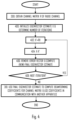
- a process for computing the beamforming coefficients comprises: obtaining (block 300) a channel matrix representing a radio channel between the apparatus and another apparatus; obtaining (block 302) an initial eigenvector estimate; computing (block 304) an intermediate eigenvector estimate based on the channel matrix and the initial eigenvector estimate; computing (block 306) an error vector representing an error between the initial eigenvector estimate and the intermediate eigenvector estimate; computing (block 308) a final eigenvector estimate based on the error vector and the intermediate eigenvector estimate; and determining (block 310) beamforming coefficients based on the final eigenvector estimate and communicating with said another apparatus by using the beamforming coefficients.
- the error vector is employed in the computation of the final eigenvector estimate.
- the use of the error vector enables reduction of computational complexity, particularly in the embodiments described below where the procedure is iterative. This results from faster convergence to an optimal or acceptable value, which means less iterations. However, some improvement can be observed even when the number of iterations is one.
- the reduction in complexity realizes in reduced number of complex multiplications. While the computational complexity is reduced, estimation accuracy remains substantially similar to state-of-the-art methods.
- the procedure of Figure 3 may be used in a transmitter for computing the beamforming coefficients that define the direction(s) to which the transmitter shall focus transmitted radio beams towards a receiver.
- the procedure of Figure 3 may be carried out in a receiver for focusing antenna gain towards a transmitter from which transmission (data or signalling information) is to be received.
- the transmitter may be the access node or a terminal device, and the receiver may equally be an access node or a terminal device. Accordingly, the procedure be used for communication between an access node and a terminal device or between two terminal devices or two access nodes. Even more generally, the procedure may be used for communication between two radio devices where one or both employ the procedure of Figure 3 .
- the procedure of Figure 3 is described in the context of computing one eigenvector estimate but the principle can be expanded to computation of multiple eigenvector estimates on the basis of the channel matrix, as described in some embodiments below.
- the channel matrix is a channel covariance matrix.
- the channel matrix may be a Hermitean matrix of Size N x N.
- N may equal to the number of antennas in the apparatus that performs the procedure of Figure 3 .
- N may be 4, 8, 16, or 32, or even higher.
- a Hermitean matrix is a square matrix that is equal to its own conjugate transpose.
- Figure 4 illustrates an embodiment where blocks 302 to 308 are iterated and the final eigenvector estimate is then computed after the last iteration.
- the following steps of Figure 3 are iterated: obtaining the initial eigenvector estimate, computing the intermediate eigenvector estimate, computing the error vector, and computing the final eigenvector estimate, wherein said computing the final eigenvector estimate for an iteration comprises removing the error vector from the initial eigenvector estimate, the resulting eigenvector estimate serving as a new initial eigenvector estimate for a subsequent iteration or, after the last iteration, as an input to said determining the beamforming coefficients.
- Figure 4 also combines some embodiments, as described below.
- the apparatus Upon computing the channel matrix R on the basis of measuring the radio channel between the transmitter and the receiver, the apparatus performing the procedure initializes an eigenvector estimate to obtain the initial eigenvector estimate X in block 400.
- the initialization in block 400 may further comprise determining a number of iterations.
- the initial eigenvector estimate may be formed of a vector (column) of a Hadamard matrix or a vector (column) of a Fourier matrix, for example. Thereafter, the vector may be multiplied by the channel matrix to obtain the initial eigenvector estimate X for the first iteration.
- block 408 it is determined whether or not to carry out another iteration. Since it is the first in the example above and the number of iterations is greater than one, the process returns to block 402 to compute the new intermediate eigenvector estimate X', new error vector X-X', and the new final eigenvector estimate X". In this manner, the determined number of iterations is performed and, upon determining in block 408 that no more iterations shall be performed, the last version of the final eigenvector estimate is taken as an output for the computation of the beamforming coefficients in block 310.
- Some embodiments for post-processing the final eigenvector estimate are described below.
- the number of iterations may have a predefined value to limit the computations and the time for computing the beamforming coefficients. Accordingly, the number of iterations can be determined beforehand in block 400. In other embodiments, the number of iterations may be a function of the value of the error vector. If the error vector is smaller (in its absolute or norm value) than a threshold, the iterations may stop. Otherwise, the iterations may be continued.
- the error vector is scaled by an error scaling factor before subtracting it from the initial eigenvector estimate to compute the final eigenvector estimate.
- the apparatus obtains an error scaling factor and scales the error vector by the error scaling factor when computing the final eigenvector estimate, e.g. before subtracting the error vector from the initial eigenvector estimate.
- a technical effect of the error scaling factor is to improve the convergence of the algorithm towards an optimal eigenvector estimate.
- the error scaling factor is based on a size of the channel matrix, e.g. N. 8.
- the value of the error scaling factor may be between 0 and 1 in order to reduce oscillation of the resulting scaled error vector.
- the error scaling factor may remain constant during the iterations of the embodiment of Figure 4 .
- the procedures are repeated at least once to compute one or more additional and different eigenvectors. Accordingly, the procedure may be used to compute a plurality of spatially (substantially) orthogonal eigenbeams to realize multiple independent spatial channels between the transmitter and the receiver.
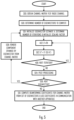
- Figure 5 illustrates such an embodiment.
- a number of eigenvectors to compute is determined in block 500.
- the number of eigenvectors (spatial channels) to employ may depend on parameters of a connection between the transmitter and the receiver, e.g. parameters of a radio resource control (RRC) connection.
- the parameters may define limits to the number of spatial channels supported.
- the number of spatial channels may be limited by the number of antennas in the transmitter and/or receiver, a connection or service type (e.g. ultra-reliable low latency connection, URLLC, versus enhanced mobile broadband connection of 5G specifications).
- the procedure may proceed to the first iteration in block 400, and blocks 400 and 402 may be carried out in the above-described manner. Thereafter, the error scaling factor may be determined, and the error vector may be scaled with the error scaling factor before subtracting the scaled error vector from the initial eigenvector estimate in block 502.
- the decision of the next iteration may be performed in block 408, and the determined number of iterations may be performed in the above-described manner.
- the final eigenvector estimate resulting from the last iteration may be subjected to post-processing in block 504.
- the post-processing may include storing the final eigenvector estimate for the computation of the beamforming coefficients.
- H in superscript denotes a Hermitean transpose operation.
- P can be defined as an intermediate vector used for computing T or directly the eigenvalue as P H X" for the respective eigenvector.
- the post-processing of block 504 may be included in the procedure of Figure 4 as well. As an output of the post-processing, the estimated eigenvector and the respective eigenvalue are provided. In block 506, it is determined whether or not to compute another eigenvector.
- Block 508 may include computing a new channel matrix as R-T, and the new channel matrix is used as the channel matrix R in the next iteration in blocks 400 and 402. In other words, a subspace spanned by the estimated eigenvector is then removed from the channel matrix. Thereafter, the next iteration is performed by using the channel matrix from which the one or more components have been removed.
- block 504 comprises computing the eigenvalue for the last eigenvector as real(S H X") where H in the superscript denotes the Hermitean transpose operation and real denotes taking a real value of the function inside the parentheses.
- the beamforming coefficients may be computed in block 510 for multiple eigenbeams for the purpose of transmission or reception of radio signals.
- Figure 5 also now illustrates the use of the error scaling factor, although the error scaling can be understood as a separate embodiment independent of the computation of the multiple eigenvectors.
- different numbers of iterations may be used for the different eigenvectors.
- the number of iterations may be based on an index of the eigenvector. For example, the number of iterations may be greater for the first eigenvector computed and smaller for one or more subsequent eigenvectors.
- the error scaling factor may be based on an index of the eigenvector. This means that the error scaling factor is different for at least two of the eigenvectors. In an embodiment, the error scaling factor is greater for the first eigenvector and smaller for one or more eigenvectors following the first eigenvector in the order of computing the eigenvectors. In other words, a first error scaling factor based on a first index is greater than or equal to a second error scaling value based on a second index, wherein the second index is greater than the first index.
- the error scaling factor is a dyadic rational which means that the error scaling factor is expressible as a fractional number where a denominator is a power of two, e.g. 1/2, 1/4, 1/8, 1/16, etc.
- An example of a sequence of error correction factors is ⁇ 0.25, 0.25, 0.125, 0.125, 0.125, 0.125 ⁇ .
- the error scaling factor is 0.25 for the first two eigenvectors and 0.125 for the subsequent eigenvectors.
- the values of the error scaling factors may thus be dependent on the number of eigenvectors to be computed (e.g. the number of antennas in the transmitter and/or receiver) and the index of the eigenvector currently under computation. In other words, the error scaling factor may be dependent on the size of the channel matrix.
- the error scaling factor is changed between at least two iterations when computing an eigenvector ( Figure 4 or the inner iteration cycle of Figure 5 ).
- the error scaling factor may be greater for a first iteration and reduced for at least one following iteration.
- normalization of the initial eigenvector estimate may be carried out during the iterations.
- the normalization has been performed with respect to a vector norm, e.g. the norm of vector X.
- a vector norm e.g. the norm of vector X.
- the normalization may be performed by multiplying the vector X by f norm .
- computation of the norm in this manner is computationally complex because of the number of multiplications and the square root function.
- Figure 6 illustrates an embodiment for performing the normalization in the procedure of Figure 4 or 5 and between blocks 400 and 402.
- the initial eigenvector estimate is normalized in block 600 to a maximum element of the initial eigenvector estimate.
- the maximum element is a maximum real value of the initial eigenvector estimate
- the maximum element is a maximum imaginary value of the initial eigenvector estimate.
- the maximum element is a sum of the maximum real value and the maximum imaginary value.
- the normalization may be performed in the post-processing in block 504.
- both normalizations of Figure 6 and 7 are performed, the simplified normalization of Figure 6 during the iterations of computing an eigenvector according to Figure 4 or 5 , and the more complex normalization in the post-processing or before computing the beamforming coefficients in block 310 or 510.
- Figure 8 illustrates an apparatus comprising a processing circuitry, such as at least one processor, and at least one memory 20 including a computer program code (software) 24, wherein the at least one memory and the computer program code (software) are configured, with the at least one processor, to cause the apparatus to carry out the process of Figure 3 or any one of its embodiments described above.
- the apparatus may be for the above-described transmitter or receiver, such as a terminal device or an access node.
- the apparatus may be a circuitry or an electronic device realizing some embodiments of the invention in the respective device.
- the apparatus carrying out the above-described functionalities may thus be comprised in such a device, e.g.
- the apparatus may comprise a circuitry such as a chip, a chipset, a processor, a micro controller, or a combination of such circuitries for the respective device.
- the at least one processor or a processing circuitry may realize a communication controller 10 controlling radio communications with the cellular network infrastructure and/or with other terminal devices or peer devices of the transmitter.
- the communication controller may be configured to establish and manage radio connections and transfer of data over the radio connections, including transmission by using the above-described modulation method.
- the communication controller may comprise a radio resource control (RRC) controller 12 configured to manage RRC connections with other radio devices, as described above.
- RRC radio resource control
- the features of RRC connections are described in greater detail in 3GPP specifications for LTE and 5G, for example. In other networks, a similar radio controller may be implemented for managing connections with other radio devices.
- the communication controller may further comprise a beamforming controller 14 configured to manage beamforming parameters of the apparatus.
- the beamforming controller 14 may operate under the control of the RRC controller 12 and, for example, receive as inputs some parameters used in the beamforming.
- An example of such a parameter is the number of eigenvectors to compute.
- the beamforming controller may comprise a channel estimator 16 configured to compute the channel matrix R according to the state of the art.
- the beamforming controller may further comprise an eigenvector computation module 15 configured to compute one or more eigenvectors on the basis of the channel matrix, e.g. perform blocks 302 to 308 of Figure 3 or respective elements in the embodiments.
- the beamforming controller may further comprise a beamforming coefficient computation module 17 configured to carry out block 310 or 510 to realize the beamforming to the desired direction from the apparatus during the communications.
- the memory 20 may be implemented using any suitable data storage technology, such as semiconductor-based memory devices, flash memory, magnetic memory devices and systems, optical memory devices and systems, fixed memory and removable memory.
- the memory 20 may comprise a database 26 storing the error scaling factors, for example.
- the memory 20 may further store a data buffer 28 for data subjected to the beamforming with the beamforming coefficients.
- the apparatus may further comprise a communication interface 22 comprising hardware and/or software for providing the apparatus with radio communication capability with one or more access nodes, as described above.
- the communication interface 22 may include, for example, an antenna, one or more radio frequency filters, a power amplifier, and one or more frequency converters.
- the communication interface 22 may comprise hardware and software needed for realizing the radio communications over the radio interface, e.g. according to specifications of an LTE or 5G radio interface.
- the apparatus of Figure 8 may further comprise an application processor operating as a source or a sink for application data to be communicated by using the beamforming coefficients.
- the application data may relate to a primary purpose of an apparatus comprising the transmitter.
- Such an apparatus may be a mobile phone, a tablet computer, a smart watch, or another personal communication device, or it may be a sensor device or another industrial device with cellular communication capability.
- the application data may comprise various data.
- the application processor may be omitted.
- circuitry refers to all of the following: (a) hardware-only circuit implementations, such as implementations in only analog and/or digital circuitry, and (b) combinations of circuits and software (and/or firmware), such as (as applicable): (i) a combination of processor(s) or (ii) portions of processor(s)/software including digital signal processor(s), software, and memory(ies) that work together to cause an apparatus to perform various functions, and (c) circuits, such as a microprocessor(s) or a portion of a microprocessor(s), that require software or firmware for operation, even if the software or firmware is not physically present.
- circuitry' applies to all uses of this term in this application.
- the term 'circuitry' would also cover an implementation of merely a processor (or multiple processors) or a portion of a processor and its (or their) accompanying software and/or firmware.
- the term 'circuitry' would also cover, for example and if applicable to the particular element, a baseband integrated circuit or applications processor integrated circuit for a mobile phone or a similar integrated circuit in a server, a cellular network device, or another network device.
- An embodiment provides a computer program embodied on a distribution medium, comprising program instructions which, when loaded into an electronic apparatus, are configured to control the apparatus to execute the embodiments described above.
- the computer program may be in source code form, object code form, or in some intermediate form, and it may be stored in some sort of carrier, which may be any entity or device capable of carrying the program.
- carrier include a record medium, computer memory, read-only memory, and a software distribution package, for example.
- the computer program may be executed in a single electronic digital computer or it may be distributed amongst several computers.
- the apparatus may also be implemented as one or more integrated circuits, such as application-specific integrated circuits ASIC.
- Other hardware embodiments are also feasible, such as a circuit built of separate logic components.
- a hybrid of these different implementations is also feasible.
Landscapes
- Engineering & Computer Science (AREA)
- Computer Networks & Wireless Communication (AREA)
- Signal Processing (AREA)
- Mobile Radio Communication Systems (AREA)
Claims (15)
- Vorrichtung, die Mittel (10, 20, 24) zum Durchführen von Folgendem umfasst:Erhalten (300) einer Kanalkovarianzmatrix, die einen Funkkanal zwischen der Vorrichtung und einer anderen Vorrichtung repräsentiert;Erhalten (302) einer anfänglichen Eigenvektorschätzung; gekennzeichnet durchBerechnen (304) einer Eigenvektorzwischenschätzung auf Basis der Kanalkovarianzmatrix und der anfänglichen Eigenvektorschätzung;Berechnen (306) eines Fehlervektors, der einen Fehler zwischen der anfänglichen Eigenvektorschätzung und der Eigenvektorzwischenschätzung repräsentiert;Berechnen (308) einer abschließenden Eigenvektorschätzung auf Basis des Fehlervektors und der Eigenvektorzwischenschätzung; undBestimmen (310) von Strahlformungskoeffizienten auf Basis der abschließenden Eigenvektorschätzung und Kommunizieren unter Verwendung der Strahlformungskoeffizienten mit der anderen Vorrichtung.
- Vorrichtung nach Anspruch 1, wobei die Mittel dazu ausgelegt sind, das Erhalten der anfänglichen Eigenvektorschätzung, das Berechnen der Eigenvektorzwischenschätzung, das Berechnen des Fehlervektors und das Berechnen der abschließenden Eigenvektorschätzung zu wiederholen, wobei das Berechnen der abschließenden Eigenvektorschätzung für eine Wiederholung das Entfernen des Fehlervektors aus der anfänglichen Eigenvektorschätzung umfasst, wobei die resultierende Eigenvektorschätzung als eine neue anfängliche Eigenvektorschätzung für eine nachfolgende Wiederholung oder, nach der letzten Wiederholung, als eine Eingabe zum Bestimmen der Strahlformungskoeffizienten dient.
- Vorrichtung nach Anspruch 2, wobei die Mittel dazu ausgelegt sind, mindestens zwei Eigenvektoren zu berechnen, und wobei sich die Anzahl von Wiederholungen zum Berechnen der abschließenden Eigenvektorschätzung für die mindestens zwei Eigenvektoren unterscheidet.
- Vorrichtung nach einem der vorhergehenden Ansprüche, wobei die Mittel zu Folgendem ausgelegt sind:Entfernen von einer oder mehreren Komponenten, die parallel zur abschließenden Eigenvektorschätzung verlaufen, aus der Kanalkovarianzmatrix; undDurchführen des Erhaltens der anfänglichen Eigenvektorschätzung, des Berechnens der Eigenvektorzwischenschätzung, des Berechnens des Fehlervektors, des Berechnens der abschließenden Eigenvektorschätzung und des Bestimmens der Strahlformungskoeffizienten für einen weiteren Eigenvektor der Kanalkovarianzmatrix, aus der die eine oder die mehreren Komponenten entfernt wurden.
- Vorrichtung nach einem der vorhergehenden Ansprüche, wobei die Mittel dazu ausgelegt sind, einen Fehlerskalierungsfaktor zu erhalten und den Fehlervektor beim Berechnen der abschließenden Eigenvektorschätzung mit dem Fehlerskalierungsfaktor zu skalieren.
- Vorrichtung nach Anspruch 5, sofern von Anspruch 2 oder 3 abhängig, wobei ein Wert des Fehlerskalierungsfaktors zwischen mindestens zwei aufeinanderfolgenden Wiederholungen geändert wird.
- Vorrichtung nach Anspruch 5 oder 6, wobei der Fehlerskalierungsfaktor auf einer Größe der Kanalkovarianzmatrix basiert.
- Vorrichtung nach einem der vorhergehenden Ansprüche 5 bis 7, wobei der Fehlerskalierungsfaktor auf einem Index des Eigenvektors basiert, wobei ein erster Fehlerskalierungsfaktor, der auf einem ersten Index basiert, größer als oder gleich einem zweiten Fehlerskalierungswert ist, der auf einem zweiten Index basiert, wobei der zweite Index größer ist als der erste Index.
- Vorrichtung nach einem der Ansprüche 5 bis 8, wobei der Fehlerskalierungsfaktor zwischen 0 und 1 liegt.
- Vorrichtung nach einem der vorhergehenden Ansprüche, wobei das Berechnen der Eigenvektorzwischenschätzung das Normalisieren der anfänglichen Eigenvektorschätzung durch ein maximales Element der anfänglichen Eigenvektorschätzung umfasst.
- Vorrichtung nach Anspruch 10, wobei das Normalisieren auf Basis eines maximalen realen Wertes der anfänglichen Eigenvektorschätzung und/oder eines maximalen imaginären Wertes der anfänglichen Eigenvektorschätzung basiert.
- Vorrichtung nach einem der vorhergehenden Ansprüche, wobei die Mittel dazu ausgelegt sind, die abschließende Eigenvektorschätzung auf eine Norm der abschließenden Eigenvektorschätzung zu normalisieren.
- Vorrichtung nach Anspruch 1, wob die Mittel mindestens einen Prozessor (10); und mindestens einen Speicher (20), der Computerprogrammcode (24) beinhaltet, umfassen.
- Verfahren, das Folgendes umfasst:Erhalten (300) einer Kanalkovarianzmatrix, die einen Funkkanal zwischen einer Vorrichtung und einer anderen Vorrichtung repräsentiert;Erhalten (302) einer anfänglichen Eigenvektorschätzung für einen Eigenvektor der Kanalmatrix; gekennzeichnet durchBerechnen (304) einer Eigenvektorzwischenschätzung auf Basis der Kanalkovarianzmatrix und der anfänglichen Eigenvektorschätzung;Berechnen (306) eines Fehlervektors, der einen Fehler zwischen der anfänglichen Eigenvektorschätzung und der Eigenvektorzwischenschätzung repräsentiert;Berechnen (308) einer abschließenden Eigenvektorschätzung auf Basis des Fehlervektors und der Eigenvektorzwischenschätzung; undBestimmen (310) von Strahlformungskoeffizienten auf Basis der abschließenden Eigenvektorschätzung und Kommunizieren unter Verwendung der Strahlformungskoeffizienten mit der anderen Vorrichtung.
- Computerprogramm, das Anweisungen zum Veranlassen der Vorrichtung nach Anspruch 1 zu Folgendem umfasst:Erhalten (300) einer Kanalkovarianzmatrix, die einen Funkkanal zwischen der Vorrichtung und einer anderen Vorrichtung repräsentiert; gekennzeichnet durchErhalten (302) einer anfänglichen Eigenvektorschätzung für einen Eigenvektor der Kanalmatrix;Berechnen (304) einer Eigenvektorzwischenschätzung auf Basis der Kanalkovarianzmatrix und der anfänglichen Eigenvektorschätzung;Berechnen (306) eines Fehlervektors, der einen Fehler zwischen der anfänglichen Eigenvektorschätzung und der Eigenvektorzwischenschätzung repräsentiert;Berechnen (308) einer abschließenden Eigenvektorschätzung auf Basis des Fehlervektors und der Eigenvektorzwischenschätzung; undBestimmen (310) von Strahlformungskoeffizienten auf Basis der abschließenden Eigenvektorschätzung und Kommunizieren unter Verwendung der Strahlformungskoeffizienten mit der anderen Vorrichtung.
Applications Claiming Priority (1)
| Application Number | Priority Date | Filing Date | Title |
|---|---|---|---|
| FI20216027 | 2021-10-05 |
Publications (2)
| Publication Number | Publication Date |
|---|---|
| EP4164137A1 EP4164137A1 (de) | 2023-04-12 |
| EP4164137B1 true EP4164137B1 (de) | 2024-07-17 |
Family
ID=83506645
Family Applications (1)
| Application Number | Title | Priority Date | Filing Date |
|---|---|---|---|
| EP22198224.2A Active EP4164137B1 (de) | 2021-10-05 | 2022-09-28 | Berechnung von strahlformungsparametern |
Country Status (3)
| Country | Link |
|---|---|
| US (1) | US11664867B2 (de) |
| EP (1) | EP4164137B1 (de) |
| CN (1) | CN115941008B (de) |
Families Citing this family (2)
| Publication number | Priority date | Publication date | Assignee | Title |
|---|---|---|---|---|
| EP4388713A1 (de) * | 2021-08-18 | 2024-06-26 | Nokia Technologies Oy | Modulationsverfahren für leistungseffiziente übertragungen |
| EP4283935A1 (de) * | 2022-05-27 | 2023-11-29 | Nokia Solutions and Networks Oy | Interferenzunterdrückung mit kombination mit reduzierter komplexität |
Family Cites Families (11)
| Publication number | Priority date | Publication date | Assignee | Title |
|---|---|---|---|---|
| DE10032426B4 (de) | 2000-07-04 | 2006-01-12 | Siemens Ag | Strahlformungsverfahren |
| KR20050073083A (ko) * | 2004-01-08 | 2005-07-13 | 엘지전자 주식회사 | 선형 시스템에서 고유벡터의 양자화 방법 |
| WO2005074147A1 (en) * | 2004-01-30 | 2005-08-11 | Universite Laval | Multi-user adaptive array receiver and method |
| US7346115B2 (en) | 2004-04-22 | 2008-03-18 | Qualcomm Incorporated | Iterative eigenvector computation for a MIMO communication system |
| US7336727B2 (en) * | 2004-08-19 | 2008-02-26 | Nokia Corporation | Generalized m-rank beamformers for MIMO systems using successive quantization |
| US7684761B2 (en) * | 2004-11-04 | 2010-03-23 | Nokia Corporation | Closed-loop signalling method for controlling multiple transmit beams and correspondingly adapted transceiver devices |
| US20070098106A1 (en) * | 2005-10-31 | 2007-05-03 | Khojastepour Mohammad A | Quantized multi-rank beamforming with structured codebook for multiple-antenna systems |
| US8321488B2 (en) * | 2008-11-04 | 2012-11-27 | Mediatek Inc. | Singular value decomposing method and related singular value decomposing device |
| JP2013543672A (ja) * | 2010-09-24 | 2013-12-05 | インテル・コーポレーション | マルチユーザ多入力多出力無線通信のデバイス、システムおよび方法 |
| EP3864759A1 (de) | 2018-10-11 | 2021-08-18 | Nokia Solutions and Networks Oy | Tiefenlern-eigenstrahlformung |
| CN112889224B (zh) | 2018-10-23 | 2023-01-06 | 上海诺基亚贝尔股份有限公司 | Mu-mimo系统中基于波束的预处理 |
-
2022
- 2022-09-28 EP EP22198224.2A patent/EP4164137B1/de active Active
- 2022-10-05 US US17/960,450 patent/US11664867B2/en active Active
- 2022-10-08 CN CN202211222735.XA patent/CN115941008B/zh active Active
Also Published As
| Publication number | Publication date |
|---|---|
| CN115941008A (zh) | 2023-04-07 |
| EP4164137A1 (de) | 2023-04-12 |
| US11664867B2 (en) | 2023-05-30 |
| CN115941008B (zh) | 2024-09-13 |
| US20230106724A1 (en) | 2023-04-06 |
Similar Documents
| Publication | Publication Date | Title |
|---|---|---|
| EP3940968B1 (de) | Verfahren und vorrichtung für ein übertragungsschema | |
| US11012133B2 (en) | Efficient data generation for beam pattern optimization | |
| US11387871B2 (en) | Regularization of covariance matrix and eigenvalue decomposition in a MIMO system | |
| US11464013B2 (en) | Coordinated link adaptation and packet scheduling in dynamic spectrum sharing | |
| EP4164137B1 (de) | Berechnung von strahlformungsparametern | |
| US11855811B1 (en) | Interference rejection combining with reduced complexity | |
| US12273161B2 (en) | Estimating a link budget | |
| US11057063B1 (en) | Dual-band digital pre-distortion | |
| EP4120579B1 (de) | Interferenzbewusste eigenstrahlformung basierend auf statistiken zweiter ordnung | |
| US11985009B2 (en) | Determining covariance using a lossy compression method | |
| WO2019222913A1 (en) | Transmission method | |
| US20250379622A1 (en) | Wideband beamforming for mimo systems | |
| EP4716110A1 (de) | Strahlformung mit geringer komplexität unter verwendung von kovarianzkompression | |
| US11916586B2 (en) | RF chain offset estimation and reduction | |
| US20240204891A1 (en) | Interference rejection in cooperative multi-point communication |
Legal Events
| Date | Code | Title | Description |
|---|---|---|---|
| PUAI | Public reference made under article 153(3) epc to a published international application that has entered the european phase |
Free format text: ORIGINAL CODE: 0009012 |
|
| STAA | Information on the status of an ep patent application or granted ep patent |
Free format text: STATUS: THE APPLICATION HAS BEEN PUBLISHED |
|
| AK | Designated contracting states |
Kind code of ref document: A1 Designated state(s): AL AT BE BG CH CY CZ DE DK EE ES FI FR GB GR HR HU IE IS IT LI LT LU LV MC MK MT NL NO PL PT RO RS SE SI SK SM TR |
|
| STAA | Information on the status of an ep patent application or granted ep patent |
Free format text: STATUS: REQUEST FOR EXAMINATION WAS MADE |
|
| 17P | Request for examination filed |
Effective date: 20231012 |
|
| RBV | Designated contracting states (corrected) |
Designated state(s): AL AT BE BG CH CY CZ DE DK EE ES FI FR GB GR HR HU IE IS IT LI LT LU LV MC MK MT NL NO PL PT RO RS SE SI SK SM TR |
|
| RIC1 | Information provided on ipc code assigned before grant |
Ipc: H04L 25/03 20060101ALN20231218BHEP Ipc: H04L 25/02 20060101ALN20231218BHEP Ipc: H04B 7/06 20060101ALI20231218BHEP Ipc: H04B 7/0456 20170101ALI20231218BHEP Ipc: H04B 7/0404 20170101AFI20231218BHEP |
|
| RIC1 | Information provided on ipc code assigned before grant |
Ipc: H04L 25/03 20060101ALN20240109BHEP Ipc: H04L 25/02 20060101ALN20240109BHEP Ipc: H04B 7/06 20060101ALI20240109BHEP Ipc: H04B 7/0456 20170101ALI20240109BHEP Ipc: H04B 7/0404 20170101AFI20240109BHEP |
|
| GRAP | Despatch of communication of intention to grant a patent |
Free format text: ORIGINAL CODE: EPIDOSNIGR1 |
|
| STAA | Information on the status of an ep patent application or granted ep patent |
Free format text: STATUS: GRANT OF PATENT IS INTENDED |
|
| RIC1 | Information provided on ipc code assigned before grant |
Ipc: H04L 25/03 20060101ALN20240125BHEP Ipc: H04L 25/02 20060101ALN20240125BHEP Ipc: H04B 7/06 20060101ALI20240125BHEP Ipc: H04B 7/0456 20170101ALI20240125BHEP Ipc: H04B 7/0404 20170101AFI20240125BHEP |
|
| INTG | Intention to grant announced |
Effective date: 20240219 |
|
| GRAS | Grant fee paid |
Free format text: ORIGINAL CODE: EPIDOSNIGR3 |
|
| GRAA | (expected) grant |
Free format text: ORIGINAL CODE: 0009210 |
|
| STAA | Information on the status of an ep patent application or granted ep patent |
Free format text: STATUS: THE PATENT HAS BEEN GRANTED |
|
| AK | Designated contracting states |
Kind code of ref document: B1 Designated state(s): AL AT BE BG CH CY CZ DE DK EE ES FI FR GB GR HR HU IE IS IT LI LT LU LV MC MK MT NL NO PL PT RO RS SE SI SK SM TR |
|
| REG | Reference to a national code |
Ref country code: CH Ref legal event code: EP |
|
| REG | Reference to a national code |
Ref country code: DE Ref legal event code: R096 Ref document number: 602022004604 Country of ref document: DE |
|
| REG | Reference to a national code |
Ref country code: IE Ref legal event code: FG4D |
|
| REG | Reference to a national code |
Ref country code: LT Ref legal event code: MG9D |
|
| REG | Reference to a national code |
Ref country code: NL Ref legal event code: MP Effective date: 20240717 |
|
| PG25 | Lapsed in a contracting state [announced via postgrant information from national office to epo] |
Ref country code: PT Free format text: LAPSE BECAUSE OF FAILURE TO SUBMIT A TRANSLATION OF THE DESCRIPTION OR TO PAY THE FEE WITHIN THE PRESCRIBED TIME-LIMIT Effective date: 20241118 |
|
| REG | Reference to a national code |
Ref country code: AT Ref legal event code: MK05 Ref document number: 1705095 Country of ref document: AT Kind code of ref document: T Effective date: 20240717 |
|
| PG25 | Lapsed in a contracting state [announced via postgrant information from national office to epo] |
Ref country code: NL Free format text: LAPSE BECAUSE OF FAILURE TO SUBMIT A TRANSLATION OF THE DESCRIPTION OR TO PAY THE FEE WITHIN THE PRESCRIBED TIME-LIMIT Effective date: 20240717 |
|
| PG25 | Lapsed in a contracting state [announced via postgrant information from national office to epo] |
Ref country code: PT Free format text: LAPSE BECAUSE OF FAILURE TO SUBMIT A TRANSLATION OF THE DESCRIPTION OR TO PAY THE FEE WITHIN THE PRESCRIBED TIME-LIMIT Effective date: 20241118 Ref country code: NL Free format text: LAPSE BECAUSE OF FAILURE TO SUBMIT A TRANSLATION OF THE DESCRIPTION OR TO PAY THE FEE WITHIN THE PRESCRIBED TIME-LIMIT Effective date: 20240717 |
|
| PG25 | Lapsed in a contracting state [announced via postgrant information from national office to epo] |
Ref country code: NO Free format text: LAPSE BECAUSE OF FAILURE TO SUBMIT A TRANSLATION OF THE DESCRIPTION OR TO PAY THE FEE WITHIN THE PRESCRIBED TIME-LIMIT Effective date: 20241017 |
|
| PG25 | Lapsed in a contracting state [announced via postgrant information from national office to epo] |
Ref country code: GR Free format text: LAPSE BECAUSE OF FAILURE TO SUBMIT A TRANSLATION OF THE DESCRIPTION OR TO PAY THE FEE WITHIN THE PRESCRIBED TIME-LIMIT Effective date: 20241018 Ref country code: FI Free format text: LAPSE BECAUSE OF FAILURE TO SUBMIT A TRANSLATION OF THE DESCRIPTION OR TO PAY THE FEE WITHIN THE PRESCRIBED TIME-LIMIT Effective date: 20240717 Ref country code: PL Free format text: LAPSE BECAUSE OF FAILURE TO SUBMIT A TRANSLATION OF THE DESCRIPTION OR TO PAY THE FEE WITHIN THE PRESCRIBED TIME-LIMIT Effective date: 20240717 |
|
| PG25 | Lapsed in a contracting state [announced via postgrant information from national office to epo] |
Ref country code: BG Free format text: LAPSE BECAUSE OF FAILURE TO SUBMIT A TRANSLATION OF THE DESCRIPTION OR TO PAY THE FEE WITHIN THE PRESCRIBED TIME-LIMIT Effective date: 20240717 |
|
| PG25 | Lapsed in a contracting state [announced via postgrant information from national office to epo] |
Ref country code: LV Free format text: LAPSE BECAUSE OF FAILURE TO SUBMIT A TRANSLATION OF THE DESCRIPTION OR TO PAY THE FEE WITHIN THE PRESCRIBED TIME-LIMIT Effective date: 20240717 |
|
| PG25 | Lapsed in a contracting state [announced via postgrant information from national office to epo] |
Ref country code: AT Free format text: LAPSE BECAUSE OF FAILURE TO SUBMIT A TRANSLATION OF THE DESCRIPTION OR TO PAY THE FEE WITHIN THE PRESCRIBED TIME-LIMIT Effective date: 20240717 Ref country code: IS Free format text: LAPSE BECAUSE OF FAILURE TO SUBMIT A TRANSLATION OF THE DESCRIPTION OR TO PAY THE FEE WITHIN THE PRESCRIBED TIME-LIMIT Effective date: 20241117 |
|
| PG25 | Lapsed in a contracting state [announced via postgrant information from national office to epo] |
Ref country code: HR Free format text: LAPSE BECAUSE OF FAILURE TO SUBMIT A TRANSLATION OF THE DESCRIPTION OR TO PAY THE FEE WITHIN THE PRESCRIBED TIME-LIMIT Effective date: 20240717 |
|
| PG25 | Lapsed in a contracting state [announced via postgrant information from national office to epo] |
Ref country code: RS Free format text: LAPSE BECAUSE OF FAILURE TO SUBMIT A TRANSLATION OF THE DESCRIPTION OR TO PAY THE FEE WITHIN THE PRESCRIBED TIME-LIMIT Effective date: 20241017 Ref country code: ES Free format text: LAPSE BECAUSE OF FAILURE TO SUBMIT A TRANSLATION OF THE DESCRIPTION OR TO PAY THE FEE WITHIN THE PRESCRIBED TIME-LIMIT Effective date: 20240717 |
|
| PG25 | Lapsed in a contracting state [announced via postgrant information from national office to epo] |
Ref country code: RS Free format text: LAPSE BECAUSE OF FAILURE TO SUBMIT A TRANSLATION OF THE DESCRIPTION OR TO PAY THE FEE WITHIN THE PRESCRIBED TIME-LIMIT Effective date: 20241017 Ref country code: PL Free format text: LAPSE BECAUSE OF FAILURE TO SUBMIT A TRANSLATION OF THE DESCRIPTION OR TO PAY THE FEE WITHIN THE PRESCRIBED TIME-LIMIT Effective date: 20240717 Ref country code: NO Free format text: LAPSE BECAUSE OF FAILURE TO SUBMIT A TRANSLATION OF THE DESCRIPTION OR TO PAY THE FEE WITHIN THE PRESCRIBED TIME-LIMIT Effective date: 20241017 Ref country code: LV Free format text: LAPSE BECAUSE OF FAILURE TO SUBMIT A TRANSLATION OF THE DESCRIPTION OR TO PAY THE FEE WITHIN THE PRESCRIBED TIME-LIMIT Effective date: 20240717 Ref country code: IS Free format text: LAPSE BECAUSE OF FAILURE TO SUBMIT A TRANSLATION OF THE DESCRIPTION OR TO PAY THE FEE WITHIN THE PRESCRIBED TIME-LIMIT Effective date: 20241117 Ref country code: HR Free format text: LAPSE BECAUSE OF FAILURE TO SUBMIT A TRANSLATION OF THE DESCRIPTION OR TO PAY THE FEE WITHIN THE PRESCRIBED TIME-LIMIT Effective date: 20240717 Ref country code: GR Free format text: LAPSE BECAUSE OF FAILURE TO SUBMIT A TRANSLATION OF THE DESCRIPTION OR TO PAY THE FEE WITHIN THE PRESCRIBED TIME-LIMIT Effective date: 20241018 Ref country code: FI Free format text: LAPSE BECAUSE OF FAILURE TO SUBMIT A TRANSLATION OF THE DESCRIPTION OR TO PAY THE FEE WITHIN THE PRESCRIBED TIME-LIMIT Effective date: 20240717 Ref country code: ES Free format text: LAPSE BECAUSE OF FAILURE TO SUBMIT A TRANSLATION OF THE DESCRIPTION OR TO PAY THE FEE WITHIN THE PRESCRIBED TIME-LIMIT Effective date: 20240717 Ref country code: BG Free format text: LAPSE BECAUSE OF FAILURE TO SUBMIT A TRANSLATION OF THE DESCRIPTION OR TO PAY THE FEE WITHIN THE PRESCRIBED TIME-LIMIT Effective date: 20240717 Ref country code: AT Free format text: LAPSE BECAUSE OF FAILURE TO SUBMIT A TRANSLATION OF THE DESCRIPTION OR TO PAY THE FEE WITHIN THE PRESCRIBED TIME-LIMIT Effective date: 20240717 |
|
| PG25 | Lapsed in a contracting state [announced via postgrant information from national office to epo] |
Ref country code: DK Free format text: LAPSE BECAUSE OF FAILURE TO SUBMIT A TRANSLATION OF THE DESCRIPTION OR TO PAY THE FEE WITHIN THE PRESCRIBED TIME-LIMIT Effective date: 20240717 Ref country code: SM Free format text: LAPSE BECAUSE OF FAILURE TO SUBMIT A TRANSLATION OF THE DESCRIPTION OR TO PAY THE FEE WITHIN THE PRESCRIBED TIME-LIMIT Effective date: 20240717 Ref country code: RO Free format text: LAPSE BECAUSE OF FAILURE TO SUBMIT A TRANSLATION OF THE DESCRIPTION OR TO PAY THE FEE WITHIN THE PRESCRIBED TIME-LIMIT Effective date: 20240717 |
|
| REG | Reference to a national code |
Ref country code: DE Ref legal event code: R097 Ref document number: 602022004604 Country of ref document: DE |
|
| PG25 | Lapsed in a contracting state [announced via postgrant information from national office to epo] |
Ref country code: MC Free format text: LAPSE BECAUSE OF FAILURE TO SUBMIT A TRANSLATION OF THE DESCRIPTION OR TO PAY THE FEE WITHIN THE PRESCRIBED TIME-LIMIT Effective date: 20240717 Ref country code: EE Free format text: LAPSE BECAUSE OF FAILURE TO SUBMIT A TRANSLATION OF THE DESCRIPTION OR TO PAY THE FEE WITHIN THE PRESCRIBED TIME-LIMIT Effective date: 20240717 |
|
| PG25 | Lapsed in a contracting state [announced via postgrant information from national office to epo] |
Ref country code: CZ Free format text: LAPSE BECAUSE OF FAILURE TO SUBMIT A TRANSLATION OF THE DESCRIPTION OR TO PAY THE FEE WITHIN THE PRESCRIBED TIME-LIMIT Effective date: 20240717 |
|
| PG25 | Lapsed in a contracting state [announced via postgrant information from national office to epo] |
Ref country code: SK Free format text: LAPSE BECAUSE OF FAILURE TO SUBMIT A TRANSLATION OF THE DESCRIPTION OR TO PAY THE FEE WITHIN THE PRESCRIBED TIME-LIMIT Effective date: 20240717 |
|
| PG25 | Lapsed in a contracting state [announced via postgrant information from national office to epo] |
Ref country code: LU Free format text: LAPSE BECAUSE OF NON-PAYMENT OF DUE FEES Effective date: 20240928 |
|
| PLBE | No opposition filed within time limit |
Free format text: ORIGINAL CODE: 0009261 |
|
| STAA | Information on the status of an ep patent application or granted ep patent |
Free format text: STATUS: NO OPPOSITION FILED WITHIN TIME LIMIT |
|
| 26N | No opposition filed |
Effective date: 20250422 |
|
| REG | Reference to a national code |
Ref country code: BE Ref legal event code: MM Effective date: 20240930 |
|
| PG25 | Lapsed in a contracting state [announced via postgrant information from national office to epo] |
Ref country code: BE Free format text: LAPSE BECAUSE OF NON-PAYMENT OF DUE FEES Effective date: 20240930 |
|
| PG25 | Lapsed in a contracting state [announced via postgrant information from national office to epo] |
Ref country code: IE Free format text: LAPSE BECAUSE OF NON-PAYMENT OF DUE FEES Effective date: 20240928 |
|
| PG25 | Lapsed in a contracting state [announced via postgrant information from national office to epo] |
Ref country code: SE Free format text: LAPSE BECAUSE OF FAILURE TO SUBMIT A TRANSLATION OF THE DESCRIPTION OR TO PAY THE FEE WITHIN THE PRESCRIBED TIME-LIMIT Effective date: 20240717 |
|
| PGFP | Annual fee paid to national office [announced via postgrant information from national office to epo] |
Ref country code: DE Payment date: 20250805 Year of fee payment: 4 |
|
| PGFP | Annual fee paid to national office [announced via postgrant information from national office to epo] |
Ref country code: FR Payment date: 20250808 Year of fee payment: 4 |
|
| PG25 | Lapsed in a contracting state [announced via postgrant information from national office to epo] |
Ref country code: IT Free format text: LAPSE BECAUSE OF FAILURE TO SUBMIT A TRANSLATION OF THE DESCRIPTION OR TO PAY THE FEE WITHIN THE PRESCRIBED TIME-LIMIT Effective date: 20240717 Ref country code: CY Free format text: LAPSE BECAUSE OF FAILURE TO SUBMIT A TRANSLATION OF THE DESCRIPTION OR TO PAY THE FEE WITHIN THE PRESCRIBED TIME-LIMIT; INVALID AB INITIO Effective date: 20220928 |
|
| PG25 | Lapsed in a contracting state [announced via postgrant information from national office to epo] |
Ref country code: HU Free format text: LAPSE BECAUSE OF FAILURE TO SUBMIT A TRANSLATION OF THE DESCRIPTION OR TO PAY THE FEE WITHIN THE PRESCRIBED TIME-LIMIT; INVALID AB INITIO Effective date: 20220928 |