EP4163700A1 - Vehicular display device - Google Patents
Vehicular display device Download PDFInfo
- Publication number
- EP4163700A1 EP4163700A1 EP21816727.8A EP21816727A EP4163700A1 EP 4163700 A1 EP4163700 A1 EP 4163700A1 EP 21816727 A EP21816727 A EP 21816727A EP 4163700 A1 EP4163700 A1 EP 4163700A1
- Authority
- EP
- European Patent Office
- Prior art keywords
- image
- display unit
- reflector
- light
- liquid crystal
- Prior art date
- Legal status (The legal status is an assumption and is not a legal conclusion. Google has not performed a legal analysis and makes no representation as to the accuracy of the status listed.)
- Granted
Links
Images




Classifications
-
- G—PHYSICS
- G02—OPTICS
- G02B—OPTICAL ELEMENTS, SYSTEMS OR APPARATUS
- G02B27/00—Optical systems or apparatus not provided for by any of the groups G02B1/00 - G02B26/00, G02B30/00
- G02B27/01—Head-up displays
- G02B27/0101—Head-up displays characterised by optical features
-
- B—PERFORMING OPERATIONS; TRANSPORTING
- B60—VEHICLES IN GENERAL
- B60K—ARRANGEMENT OR MOUNTING OF PROPULSION UNITS OR OF TRANSMISSIONS IN VEHICLES; ARRANGEMENT OR MOUNTING OF PLURAL DIVERSE PRIME-MOVERS IN VEHICLES; AUXILIARY DRIVES FOR VEHICLES; INSTRUMENTATION OR DASHBOARDS FOR VEHICLES; ARRANGEMENTS IN CONNECTION WITH COOLING, AIR INTAKE, GAS EXHAUST OR FUEL SUPPLY OF PROPULSION UNITS IN VEHICLES
- B60K35/00—Instruments specially adapted for vehicles; Arrangement of instruments in or on vehicles
- B60K35/20—Output arrangements, i.e. from vehicle to user, associated with vehicle functions or specially adapted therefor
- B60K35/21—Output arrangements, i.e. from vehicle to user, associated with vehicle functions or specially adapted therefor using visual output, e.g. blinking lights or matrix displays
- B60K35/23—Head-up displays [HUD]
-
- G—PHYSICS
- G02—OPTICS
- G02F—OPTICAL DEVICES OR ARRANGEMENTS FOR THE CONTROL OF LIGHT BY MODIFICATION OF THE OPTICAL PROPERTIES OF THE MEDIA OF THE ELEMENTS INVOLVED THEREIN; NON-LINEAR OPTICS; FREQUENCY-CHANGING OF LIGHT; OPTICAL LOGIC ELEMENTS; OPTICAL ANALOGUE/DIGITAL CONVERTERS
- G02F1/00—Devices or arrangements for the control of the intensity, colour, phase, polarisation or direction of light arriving from an independent light source, e.g. switching, gating or modulating; Non-linear optics
- G02F1/01—Devices or arrangements for the control of the intensity, colour, phase, polarisation or direction of light arriving from an independent light source, e.g. switching, gating or modulating; Non-linear optics for the control of the intensity, phase, polarisation or colour
- G02F1/13—Devices or arrangements for the control of the intensity, colour, phase, polarisation or direction of light arriving from an independent light source, e.g. switching, gating or modulating; Non-linear optics for the control of the intensity, phase, polarisation or colour based on liquid crystals, e.g. single liquid crystal display cells
- G02F1/133—Constructional arrangements; Operation of liquid crystal cells; Circuit arrangements
- G02F1/1333—Constructional arrangements; Manufacturing methods
- G02F1/133382—Heating or cooling of liquid crystal cells other than for activation, e.g. circuits or arrangements for temperature control, stabilisation or uniform distribution over the cell
- G02F1/133385—Heating or cooling of liquid crystal cells other than for activation, e.g. circuits or arrangements for temperature control, stabilisation or uniform distribution over the cell with cooling means, e.g. fans
-
- G—PHYSICS
- G02—OPTICS
- G02F—OPTICAL DEVICES OR ARRANGEMENTS FOR THE CONTROL OF LIGHT BY MODIFICATION OF THE OPTICAL PROPERTIES OF THE MEDIA OF THE ELEMENTS INVOLVED THEREIN; NON-LINEAR OPTICS; FREQUENCY-CHANGING OF LIGHT; OPTICAL LOGIC ELEMENTS; OPTICAL ANALOGUE/DIGITAL CONVERTERS
- G02F1/00—Devices or arrangements for the control of the intensity, colour, phase, polarisation or direction of light arriving from an independent light source, e.g. switching, gating or modulating; Non-linear optics
- G02F1/01—Devices or arrangements for the control of the intensity, colour, phase, polarisation or direction of light arriving from an independent light source, e.g. switching, gating or modulating; Non-linear optics for the control of the intensity, phase, polarisation or colour
- G02F1/15—Devices or arrangements for the control of the intensity, colour, phase, polarisation or direction of light arriving from an independent light source, e.g. switching, gating or modulating; Non-linear optics for the control of the intensity, phase, polarisation or colour based on an electrochromic effect
- G02F1/153—Constructional details
- G02F1/157—Structural association of cells with optical devices, e.g. reflectors or illuminating devices
-
- B—PERFORMING OPERATIONS; TRANSPORTING
- B60—VEHICLES IN GENERAL
- B60K—ARRANGEMENT OR MOUNTING OF PROPULSION UNITS OR OF TRANSMISSIONS IN VEHICLES; ARRANGEMENT OR MOUNTING OF PLURAL DIVERSE PRIME-MOVERS IN VEHICLES; AUXILIARY DRIVES FOR VEHICLES; INSTRUMENTATION OR DASHBOARDS FOR VEHICLES; ARRANGEMENTS IN CONNECTION WITH COOLING, AIR INTAKE, GAS EXHAUST OR FUEL SUPPLY OF PROPULSION UNITS IN VEHICLES
- B60K2360/00—Indexing scheme associated with groups B60K35/00 or B60K37/00 relating to details of instruments or dashboards
- B60K2360/20—Optical features of instruments
- B60K2360/23—Optical features of instruments using reflectors
-
- B—PERFORMING OPERATIONS; TRANSPORTING
- B60—VEHICLES IN GENERAL
- B60Y—INDEXING SCHEME RELATING TO ASPECTS CROSS-CUTTING VEHICLE TECHNOLOGY
- B60Y2304/00—Optimising design; Manufacturing; Testing
- B60Y2304/01—Minimizing space with more compact designs or arrangements
-
- G—PHYSICS
- G02—OPTICS
- G02B—OPTICAL ELEMENTS, SYSTEMS OR APPARATUS
- G02B27/00—Optical systems or apparatus not provided for by any of the groups G02B1/00 - G02B26/00, G02B30/00
- G02B27/01—Head-up displays
- G02B27/0101—Head-up displays characterised by optical features
- G02B2027/014—Head-up displays characterised by optical features comprising information/image processing systems
-
- G—PHYSICS
- G06—COMPUTING OR CALCULATING; COUNTING
- G06F—ELECTRIC DIGITAL DATA PROCESSING
- G06F3/00—Input arrangements for transferring data to be processed into a form capable of being handled by the computer; Output arrangements for transferring data from processing unit to output unit, e.g. interface arrangements
- G06F3/14—Digital output to display device ; Cooperation and interconnection of the display device with other functional units
- G06F3/147—Digital output to display device ; Cooperation and interconnection of the display device with other functional units using display panels
-
- G—PHYSICS
- G09—EDUCATION; CRYPTOGRAPHY; DISPLAY; ADVERTISING; SEALS
- G09G—ARRANGEMENTS OR CIRCUITS FOR CONTROL OF INDICATING DEVICES USING STATIC MEANS TO PRESENT VARIABLE INFORMATION
- G09G2380/00—Specific applications
- G09G2380/10—Automotive applications
Definitions
- the present invention relates to a display device equipped on a vehicle such as an automobile, and more specifically to a head-up display device (in the following, an HUD device).
- a head-up display device in the following, an HUD device.
- Patent Literature 1 proposes an HUD device in which light (in the following, image light) of an image displayed on a display unit such as a liquid crystal panel is sequentially reflected off a plane mirror and a concave mirror and projected onto the windshield of an automobile to visually recognize a virtual image.
- Patent Literature 1 JP-A-2018-174583
- the HUD device of Patent Literature 1 In order to further downsize the HUD device of Patent Literature 1, it is necessary to dispose the display unit, the plane mirror, and the concave mirror as close as possible.
- the HUD device of Patent Literature 1 has a configuration in which the optical path of the image light from the display unit to the windshield is bent in a folded state along the front-rear direction of the automobile by the plane mirror and the concave mirror, a part of the image light reflected off the plane mirror may be shielded by the display unit. In addition, a part of the image light reflected off the concave mirror may be shielded by the plane mirror.
- the shielded image light is not projected onto the windshield, a part of the image is not displayed, and the display quality of the image on the HUD device is degraded.
- the display unit and the plane mirror may be heated by the shielded light.
- the liquid crystal device is likely to be thermally damaged by heat generated by a light source that emits image light from the liquid crystal device, and the heat resistance of the HUD device is reduced.
- An object of the present invention is to provide a small-sized HUD device having a high image display quality and a high heat resistance.
- the present invention is a vehicle display device including: an image display unit including a display panel that displays an image; and an optical system that projects image light of the displayed image onto a windshield of a vehicle, in which a virtual image of the image is visually recognized by light reflected off the windshield.
- an effective display region in which the image is displayed is set to a region on a side close to one end of the display panel.
- the optical system includes: a first reflector that reflects image light emitted from the image display unit; and a second reflector that reflects reflected light of the first reflector toward the windshield, and an optical path of image light from the image display unit to the second reflector is set in a folded state.
- the image display unit is disposed to face the first reflector, and the display panel is disposed in an attitude in which one end of the display panel faces the second reflector side.
- the display panel is formed of a transmissive liquid crystal panel, the liquid crystal panel is supported by a case, and a light source for a liquid crystal panel backlight and a heat sink are placed in the case.
- the ineffective display region except the effective display region is thermally coupled to the heat sink.
- a high quality, small-sized vehicle display device capable of preventing image light that is emitted from an image display unit from being shielded, and capable of displaying a suitable image.
- a vehicle display device having a high heat resistance and an enhanced heat dissipation effect in an image display unit.
- Fig. 1 is a conceptual configuration diagram of an HUD device 1 applied to an automobile.
- the HUD device 1 is placed in a dashboard DB of an automobile, and image light L emitted from the HUD device 1 is projected onto a windshield (referred to as a windshield) WS of the automobile through an upper surface opening H of the dashboard DB.
- the projected image light L is reflected off the windshield WS and directed to an occupant M such as a driver of the automobile.
- the image light L enters the eyes of the occupant M, the occupant M can visually recognize the virtual image I by the image light at the front position of the automobile through the windshield WS, and the image is displayed.
- a speedometer image and a navigation image are displayed side by side in the left-right direction.
- the up-down direction and the front-rear direction respectively indicate the up-down direction and the front-rear direction based on the automobile.
- Fig. 2 shows a schematic view of the HUD device 1 viewed from a side direction.
- the HUD device 1 includes an image display unit 2 and an optical system 3 that projects an image displayed on the image display unit 2 onto the windshield WS.
- the image display unit 2 includes a display panel, which will be described later, and displays an image on the image display surface of the display panel.
- the optical system 3 includes a first reflector 31 that reflects the image light L of the image displayed on the image display unit 2, and a second reflector 32 that further reflects the light reflected off the first reflection 31 and projects the light onto the windshield WS.
- the first reflector 31 is formed of a convex mirror
- the second reflector 32 is formed of a concave mirror.
- the concave mirror 32 includes a spherical surface, an aspherical surface, or a free-form surface having a curvature that achieves a required focal length.
- the convex mirror 31 is provided to improve aberration in the concave mirror 31 and to substantially extend the focal length of the concave mirror 32.
- the HUD device 1 is configured such that the image displayed on the image display unit 2 is disposed within the focal length of the concave mirror 32, and thus the occupant M can visually recognize the virtual image I of the displayed image.
- Fig. 3 is a cross-sectional view showing a schematic configuration of the image display unit 2
- Fig. 4 is an exploded perspective view of the schematic configuration.
- the image display unit 2 includes a case 21 formed of a member having a high thermal conductivity, and a transmissive liquid crystal panel 22 as a display panel is supported on at least a part of the upper surface of the case 21.
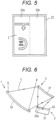
- a part of the region of the image display surface is set as an effective display region 22a. That is, since the aspect ratio of the image display surface of the liquid crystal panel 22 is different from the aspect ratio of the image I displayed through the windshield WS shown in Fig. 1 , a region corresponding to the aspect ratio of the image I in the entire region of the image display surface is set as the effective display region 22a, and the image I is displayed in the effective display region 22a.
- the aspect ratio of the image display surface of the liquid crystal panel 22 is 3 : 4
- the aspect ratio of the image to be displayed is substantially 1 : 2
- a region satisfying the aspect ratio of the image is set as the effective display region 22a.
- the left direction of the liquid crystal panel 22 corresponds to the lower part of the image displayed in Fig. 5
- the left side of the liquid crystal panel 22 is set as the screen downward direction. Therefore, the effective display region 22a is set to a region on the side close to the left end in Fig. 5 , i.e., a region on the side close to one end corresponding to the lower side of the screen of the liquid crystal panel 22.
- a region on the right side from the effective display region 22a of the liquid crystal panel 22 is set as an ineffective display region 22b that does not contribute to image display.
- the case 21 includes a light source chamber 21a in which a region corresponding to the effective display region 22a of the liquid crystal panel 22 is recessed downward from the upper surface, and a backlight source 23 is placed on the inner bottom surface of the light source chamber 21a.
- the backlight source 23 includes a circuit board 23b on which a light emitting diode (LED) 23a is mounted, and white light emitted when the LED 23a emits light is projected onto the back surface side of the liquid crystal panel 22.
- the inner wall surface of the light source chamber 21a is inclined so as to spread from the LED 23a toward the liquid crystal panel 22, and the white light of the LED 23a is reflected off the inner wall surface to be directed toward the liquid crystal panel 22.
- the white light projected onto the liquid crystal panel 22 is transmitted through the liquid crystal panel 22 and emitted as image light having a required hue.
- the liquid crystal panel 22 is placed on the upper surface of the case 21, and then fixed to the case 21 with a cover 24 laid so as to cover the liquid crystal panel 22 from above.
- the cover 24 is provided with an opening window 24a through which the effective display region 22a of the liquid crystal panel 22 is partially exposed, and is attached so as to cover another region including the ineffective display region 22b such that its peripheral edge is fitted to the case 21.
- heat transfer sheets 25 and 26 formed of an elastic material having a high thermal conductivity are provided, respectively.
- opening windows 25a and 26a through which the effective display region 22a is exposed are formed.
- each of the heat transfer sheets 25 and 26 equalizes an external force applied to the liquid crystal panel 22 by its own elasticity, and prevents a partial stress, which is likely to cause mechanical damage to the liquid crystal panel 22, from occurring.
- the heat transfer sheets 25 and 26 are placed in the peripheral edge region of the liquid crystal panel 22 and the region of the ineffective display region 22b excluding the effective display region 22a.
- a plurality of heat dissipation fins 21b is formed on the outer wall surface of a part excluding the light source chamber 21a, and heat generated in the case 21, specifically, heat generated in the LEDs 23a and heat generated in the liquid crystal panel 22 are dissipated through the heat dissipation fins 21b.
- heat generated in the LEDs 23a and heat generated in the liquid crystal panel 22 are dissipated through the heat dissipation fins 21b.
- the image display unit 2 having the above configuration, when the liquid crystal panel 22 is driven by a control unit, not shown in the drawing, a predetermined image is displayed in the effective display region 22a of the liquid crystal panel 22.
- the speedometer image and the navigation image are displayed side by side in the left-right direction, as schematically shown in Fig. 5 .
- the LED 23a emits light, and white light emitted from the LED 23a is applied to the effective display region 22a.
- the white light emitted from the LED 23a is reflected off the inner wall of the light source chamber 21a, and thus the white light as backlight having a uniform luminance distribution is applied to the effective display region 22a.
- the light transmitted through the displayed image I i.e., the image light L is emitted from the liquid crystal panel 22.
- the ineffective display region 22b excluding the effective display region 22a is in close contact with the case 21 and the cover 24 through the heat transfer sheets 25 and 26, and thus it is possible to increase the heat dissipation area in the liquid crystal panel 22 as large as possible, and it is possible to enhance the heat dissipation effect.
- a temperature rise in the liquid crystal panel 22 is restrained, and the thermal reliability of the liquid crystal panel 22 is improved.
- Fig. 6 is a schematic enlarged side view showing a positional relationship between the image display unit 2 and the optical system 2.
- the image display unit 2 is disposed obliquely downward in front of the convex mirror 31, and image light emitted from the effective display region 22a of the liquid crystal panel 22 is projected onto the convex mirror 31.
- the projected image light is reflected toward the front at the convex mirror 31, projected onto the concave mirror 32, reflected, and projected onto the windshield WS of the automobile through the upper surface opening H of the dashboard DB. Therefore, the image light from the liquid crystal panel 22 is projected onto the windshield WS through the optical path in a folded state along the front-rear direction of the automobile.
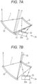
- a part X1 of the image display unit 2A may enter the optical path of the image light L, and a part of the image light L may be shielded. That is, as dotted in Fig 7(a) , a part of the image light L emitted from the effective display region 22a of the liquid crystal panel 22 is shielded and is not projected onto the windshield WS, and thus suitable image display may not be performed.
- the image display unit 2A in which the effective display region 22a is set in the central region in the up-down direction of the screen of the liquid crystal panel 22 or in the screen upward direction, when the effective display region 22a is set at a predetermined position to the convex mirror 31, the image display unit 2 is disposed at a position close to the side of the concave mirror 32, and the part X1 of the image display unit 2A is prone to enter the optical path of the image light L.
- a part X2 of the convex mirror 31 may enter the optical path of the image light L reflected off the concave mirror 32 this time as shown in a second reference example in Fig. 7(b) . Also in this case, as dotted in Fig. 7(b) , a part of the image light L projected onto the windshield WS is shielded, and suitable image display fails to be performed.
- the region of the optical path of the image light L is widened accordingly, and the part X2 of the convex mirror 31 is prone to enter the optical path.
- the effective display region 22a of the liquid crystal panel 22 is placed in a region on a side close to one end corresponding to the screen downward direction of the image display unit 2. Then, the image display unit 2 is placed in an attitude in which the one end is directed to the side on which the image light L is reflected off the convex mirror 31, i.e., directed to the concave mirror 32 side disposed in front.
- the liquid crystal panel 22 is placed on one side of the normal, the concave mirror 32 is disposed on the other side of the normal, and the effective display region 22a of the liquid crystal panel 22 is placed in an attitude directed toward the side close to the normal.
- the convex mirror 31 can be downsized, and the convex mirror 31 can be prevented from entering the optical path of the image light L reflected off the concave mirror 32 as in the second reference example. Therefore, the radius of curvature of concave mirror 32 is reduced in order to increase the magnification ratio of the image to be displayed, and suitable image display can be performed even though the end of concave mirror 32 projects in the direction of the display device 2.
- the first reflector may be formed of a concave mirror 31A.
- the first reflector may be formed of a plane mirror.
- the concave mirror 31A is referred to as a first concave mirror
- the concave mirror 32 same as that in the above embodiment is referred to as a second concave mirror.
- the convex mirror is formed of the first concave mirror 31A
- the up-down positional relationship between the image display unit 2 and first concave mirror 31A can be reversed.
- the image light of the image display unit 2 reflected off the first concave mirror 31A has a substantially horizontal optical path, and the image display unit 2 is not prone to enter the respective optical paths of the image light L reflected off the first concave mirror 31A and the image light L reflected off the second concave mirror 32. Therefore, the interval dimension between the image display unit 2 and first concave mirror 31A can be further reduced.
- the form including the first concave mirror 31A is suitable for application to an HUD device in which the radius of curvature of the second concave mirror 32 is made large enough.
- Fig. 9 is a longitudinal sectional view of a first modification example of the image display unit 2. The interval and number of the heat dissipation fins 21b formed in the case 21 are partially different. In addition, although not shown in the drawing, the dimensions of the heat dissipation fins may be partially different.
- the case 21 and the heat dissipation fins 21b may be partially changed to a material having a low heat conductivity.
- the heat dissipation distribution in the case 21 is controlled, and a suitable heat dissipation effect in each of the LED 23a and the liquid crystal panel 22 can be obtained.
- Fig. 10 is a longitudinal sectional view of a second modification example of the image display unit 2.
- a heat dissipation fan 27 is attached at a position facing the heat dissipation fins 21b formed in the case 1.
- the heat dissipation fan 27 is driven synchronously, and thus a heat dissipation effect in the case 21, i.e., the heat dissipation fins 21b can be enhanced.
- the heat dissipation fan 27 can be similarly applied to the case 21 of the image display unit 2 of the first modification example shown in Fig. 9 .
- Fig. 11 is a longitudinal sectional view of a third modification example of the image display unit 2.
- an auxiliary heat dissipation fin 28 is integrally formed. That is, one or more auxiliary heat dissipation fins 28 are integrally formed on a part of the surface of the cover 24, specifically in a region corresponding to the ineffective display region 22b of the liquid crystal panel 22.
- the heat generated in the liquid crystal panel 22 is transferred from the ineffective display region 22b to the cover 24, and is dissipated from the auxiliary heat dissipation fin 28.
- heat is dissipated from the ineffective display region 22b having a relatively large area, and thus the heat dissipation effect is enhanced.
- the auxiliary heat dissipation fin 28 is placed so as not to interfere with other components such as the convex mirror 31 when placed in the HUD device 1.
- Fig. 12 is a longitudinal sectional view of a fourth modification example of the image display unit 2.
- No heat dissipation fin is formed in the case 21, and the case 21 is thermally connected through a heat pipes 29 to a separate heat sink 4 separately formed.
- the separate heat sink 4 is placed outside a housing 11 of the HUD device 1 that internally houses the image display unit 2.
- the case 21 and the separate heat sink 4 are connected to each other through the heat pipe 29 that extends penetrating the housing 11. Heat generated in the LED 23a and the liquid crystal panel 22 is transferred from the case 21 to the separate heat sink 4 through the heat pipe 29, and is dissipated from the separate heat sink 4. Since the separate heat sink 4 is disposed outside the housing 11, the heat dissipation effect is further enhanced.
- the separate heat sink 4 may be connected from the cover 24 through the heat pipe 29 to enhance the heat dissipation effect.
- the heat transfer sheets 25 and 26 provided in the image display unit 2 are preferably members having a high heat conductivity and having an effect of absorbing stress between the liquid crystal panel 22 and the case 21 and between the liquid crystal panel 22 and the cover 24, and for example, heat transfer grease may be used.
- heat transfer grease when used, it can be easily imagined that the grease flows out due to the influence of the use environment or the like, and a defect of adhesion to the effective display region 22a occurs. Therefore, it goes without saying that a structure which prevents outflow is provided at the boundary between the effective display region and the heat transfer sheets 25 and 26.
- the display panel of the image display unit 2 since the display panel of the image display unit 2 only has to have a configuration that emits image light corresponding to an image to be displayed, the display panel may be configured of a DMD device in which micro mirrors are disposed in a matrix to selectively reflect light of a light source and emit the image light. Alternatively, it may be composed of an organic EL or an electromic element.
- the windshield in the present invention is not limited to the windshield of an automobile described in the embodiment, and may be a part of a vehicle body such as a translucent window provided in a vehicle.
Landscapes
- Physics & Mathematics (AREA)
- Nonlinear Science (AREA)
- Optics & Photonics (AREA)
- General Physics & Mathematics (AREA)
- Engineering & Computer Science (AREA)
- Chemical & Material Sciences (AREA)
- Mechanical Engineering (AREA)
- Transportation (AREA)
- Combustion & Propulsion (AREA)
- Mathematical Physics (AREA)
- Crystallography & Structural Chemistry (AREA)
- Instrument Panels (AREA)
- Liquid Crystal (AREA)
- Controls And Circuits For Display Device (AREA)
- Electrochromic Elements, Electrophoresis, Or Variable Reflection Or Absorption Elements (AREA)
- Devices For Indicating Variable Information By Combining Individual Elements (AREA)
Abstract
Description
- The present invention relates to a display device equipped on a vehicle such as an automobile, and more specifically to a head-up display device (in the following, an HUD device).
- As the HUD device, there is proposed a device in which light forming an image is projected onto the windshield of an automobile such that an occupant such as a driver can visually recognize a virtual image of the image with the reflected light. Note that in the following, making a virtual image visible is also referred to as displaying an image.
Patent Literature 1 proposes an HUD device in which light (in the following, image light) of an image displayed on a display unit such as a liquid crystal panel is sequentially reflected off a plane mirror and a concave mirror and projected onto the windshield of an automobile to visually recognize a virtual image. - In this type of HUD device, in order to configure the size of an image to be displayed, i.e., the size of a virtual image to be a certain size, it is necessary to set the focal length of the concave mirror that creates the virtual image to a length correspondingly. In
Patent Literature 1, image light of the display unit is once reflected off the plane mirror, and thus the size of the HUD device, specifically, the length of the concave mirror in the optical axis direction can be shortened, and a small-sized HUD device can be configured. Note that a configuration using a convex mirror instead of the plane mirror is also proposed. - Patent Literature 1:
JP-A-2018-174583 - In order to further downsize the HUD device of
Patent Literature 1, it is necessary to dispose the display unit, the plane mirror, and the concave mirror as close as possible. However, since the HUD device ofPatent Literature 1 has a configuration in which the optical path of the image light from the display unit to the windshield is bent in a folded state along the front-rear direction of the automobile by the plane mirror and the concave mirror, a part of the image light reflected off the plane mirror may be shielded by the display unit. In addition, a part of the image light reflected off the concave mirror may be shielded by the plane mirror. - As described above, when a part of the image light is shielded, the shielded image light is not projected onto the windshield, a part of the image is not displayed, and the display quality of the image on the HUD device is degraded. In addition, the display unit and the plane mirror may be heated by the shielded light. Specifically, in the case in which the display unit includes a liquid crystal device, the liquid crystal device is likely to be thermally damaged by heat generated by a light source that emits image light from the liquid crystal device, and the heat resistance of the HUD device is reduced.
- An object of the present invention is to provide a small-sized HUD device having a high image display quality and a high heat resistance.
- The present invention is a vehicle display device including: an image display unit including a display panel that displays an image; and an optical system that projects image light of the displayed image onto a windshield of a vehicle, in which a virtual image of the image is visually recognized by light reflected off the windshield. In the image display unit, an effective display region in which the image is displayed is set to a region on a side close to one end of the display panel.
- In a preferred embodiment of the present invention, the optical system includes: a first reflector that reflects image light emitted from the image display unit; and a second reflector that reflects reflected light of the first reflector toward the windshield, and an optical path of image light from the image display unit to the second reflector is set in a folded state. In addition to this, the image display unit is disposed to face the first reflector, and the display panel is disposed in an attitude in which one end of the display panel faces the second reflector side.
- As a preferred embodiment of the image display unit in the present invention, the display panel is formed of a transmissive liquid crystal panel, the liquid crystal panel is supported by a case, and a light source for a liquid crystal panel backlight and a heat sink are placed in the case. In addition to this, in the display panel, the ineffective display region except the effective display region is thermally coupled to the heat sink.
- According to the present invention, there is provided a high quality, small-sized vehicle display device capable of preventing image light that is emitted from an image display unit from being shielded, and capable of displaying a suitable image. In addition, according to the present invention, there is provided a vehicle display device having a high heat resistance and an enhanced heat dissipation effect in an image display unit.
-
-
Fig. 1 is a conceptual configuration diagram of an HUD device; -
Fig. 2 is a schematic view of the HUD device viewed from the side; -
Fig. 3 is a longitudinal sectional view of an image display unit; -
Fig. 4 is a schematic partially exploded perspective view of the image display unit; -
Fig. 5 is a plan view of a liquid crystal panel; -
Fig. 6 is a schematic side view showing a positional relationship between the image display unit and an optical system of the HUD device; -
Fig. 7 shows schematic side views of the HUD device, (a) is a first reference example and (b) is a second reference example; -
Fig. 8 is a schematic side view of a modification example of the HUD device; -
Fig. 9 is a longitudinal sectional view of a first modification example of the image display unit; -
Fig. 10 is a longitudinal sectional view of a second modification example of the image display unit; -
Fig. 11 is a longitudinal sectional view of a third modification example of the image display unit; and -
Fig. 12 is a longitudinal sectional view of a fourth modification example of the image display unit. - Next, an embodiment of the present invention will be described with reference to the drawings.
Fig. 1 is a conceptual configuration diagram of anHUD device 1 applied to an automobile. TheHUD device 1 is placed in a dashboard DB of an automobile, and image light L emitted from theHUD device 1 is projected onto a windshield (referred to as a windshield) WS of the automobile through an upper surface opening H of the dashboard DB. The projected image light L is reflected off the windshield WS and directed to an occupant M such as a driver of the automobile. When the image light L enters the eyes of the occupant M, the occupant M can visually recognize the virtual image I by the image light at the front position of the automobile through the windshield WS, and the image is displayed. In this example, as the image to be displayed, a speedometer image and a navigation image are displayed side by side in the left-right direction. Note that in the following, the up-down direction and the front-rear direction respectively indicate the up-down direction and the front-rear direction based on the automobile. -
Fig. 2 shows a schematic view of theHUD device 1 viewed from a side direction. TheHUD device 1 includes animage display unit 2 and anoptical system 3 that projects an image displayed on theimage display unit 2 onto the windshield WS. Theimage display unit 2 includes a display panel, which will be described later, and displays an image on the image display surface of the display panel. Theoptical system 3 includes afirst reflector 31 that reflects the image light L of the image displayed on theimage display unit 2, and asecond reflector 32 that further reflects the light reflected off thefirst reflection 31 and projects the light onto the windshield WS. Thefirst reflector 31 is formed of a convex mirror, and thesecond reflector 32 is formed of a concave mirror. - The
concave mirror 32 includes a spherical surface, an aspherical surface, or a free-form surface having a curvature that achieves a required focal length. Theconvex mirror 31 is provided to improve aberration in theconcave mirror 31 and to substantially extend the focal length of theconcave mirror 32. TheHUD device 1 is configured such that the image displayed on theimage display unit 2 is disposed within the focal length of theconcave mirror 32, and thus the occupant M can visually recognize the virtual image I of the displayed image. -
Fig. 3 is a cross-sectional view showing a schematic configuration of theimage display unit 2, andFig. 4 is an exploded perspective view of the schematic configuration. Theimage display unit 2 includes acase 21 formed of a member having a high thermal conductivity, and a transmissiveliquid crystal panel 22 as a display panel is supported on at least a part of the upper surface of thecase 21. As the image display surface of theliquid crystal panel 22 is schematically shown inFig. 5 , a part of the region of the image display surface is set as aneffective display region 22a. That is, since the aspect ratio of the image display surface of theliquid crystal panel 22 is different from the aspect ratio of the image I displayed through the windshield WS shown inFig. 1 , a region corresponding to the aspect ratio of the image I in the entire region of the image display surface is set as theeffective display region 22a, and the image I is displayed in theeffective display region 22a. - In this embodiment, since the aspect ratio of the image display surface of the
liquid crystal panel 22 is 3 : 4, whereas the aspect ratio of the image to be displayed is substantially 1 : 2, a region satisfying the aspect ratio of the image is set as theeffective display region 22a. In addition, since the left direction of theliquid crystal panel 22 corresponds to the lower part of the image displayed inFig. 5 , the left side of theliquid crystal panel 22 is set as the screen downward direction. Therefore, theeffective display region 22a is set to a region on the side close to the left end inFig. 5 , i.e., a region on the side close to one end corresponding to the lower side of the screen of theliquid crystal panel 22. A region on the right side from theeffective display region 22a of theliquid crystal panel 22 is set as anineffective display region 22b that does not contribute to image display. - The
case 21 includes alight source chamber 21a in which a region corresponding to theeffective display region 22a of theliquid crystal panel 22 is recessed downward from the upper surface, and abacklight source 23 is placed on the inner bottom surface of thelight source chamber 21a. Thebacklight source 23 includes acircuit board 23b on which a light emitting diode (LED) 23a is mounted, and white light emitted when theLED 23a emits light is projected onto the back surface side of theliquid crystal panel 22. The inner wall surface of thelight source chamber 21a is inclined so as to spread from theLED 23a toward theliquid crystal panel 22, and the white light of theLED 23a is reflected off the inner wall surface to be directed toward theliquid crystal panel 22. The white light projected onto theliquid crystal panel 22 is transmitted through theliquid crystal panel 22 and emitted as image light having a required hue. - The
liquid crystal panel 22 is placed on the upper surface of thecase 21, and then fixed to thecase 21 with acover 24 laid so as to cover theliquid crystal panel 22 from above. Thecover 24 is provided with anopening window 24a through which theeffective display region 22a of theliquid crystal panel 22 is partially exposed, and is attached so as to cover another region including theineffective display region 22b such that its peripheral edge is fitted to thecase 21. - Between the
case 21 and theliquid crystal panel 22 and between theliquid crystal panel 22 and thecover 24,heat transfer sheets heat transfer sheets windows effective display region 22a is exposed are formed. In addition, each of theheat transfer sheets liquid crystal panel 22 by its own elasticity, and prevents a partial stress, which is likely to cause mechanical damage to theliquid crystal panel 22, from occurring. Theheat transfer sheets liquid crystal panel 22 and the region of theineffective display region 22b excluding theeffective display region 22a. - Furthermore, in the
case 21, a plurality ofheat dissipation fins 21b is formed on the outer wall surface of a part excluding thelight source chamber 21a, and heat generated in thecase 21, specifically, heat generated in theLEDs 23a and heat generated in theliquid crystal panel 22 are dissipated through theheat dissipation fins 21b. Generally, in an HUD device having a large display magnification of a display image, the density of light of the display image decreases. Therefore, it is necessary to use an LED having a high luminous intensity, which leads to an increase in generating heat in the LED. In addition, accordingly, the heat generated by the light absorbing action in the liquid crystal panel also increases. - In the
image display unit 2 having the above configuration, when theliquid crystal panel 22 is driven by a control unit, not shown in the drawing, a predetermined image is displayed in theeffective display region 22a of theliquid crystal panel 22. Here, corresponding to the image I shown inFig. 1 , the speedometer image and the navigation image are displayed side by side in the left-right direction, as schematically shown inFig. 5 . In addition, at the same time, theLED 23a emits light, and white light emitted from theLED 23a is applied to theeffective display region 22a. The white light emitted from theLED 23a is reflected off the inner wall of thelight source chamber 21a, and thus the white light as backlight having a uniform luminance distribution is applied to theeffective display region 22a. As a result, the light transmitted through the displayed image I, i.e., the image light L is emitted from theliquid crystal panel 22. - As described above, when the light of the
LED 23a is transmitted through theliquid crystal panel 22, a part of the light is converted into heat by theliquid crystal panel 22, and heat is generated by theLED 23a emitting light. The heat is transferred to thecase 21, and a part of the heat is transferred to thecase 21 through thecover 24, further transferred to theheat dissipation fins 21b as a heat sink formed in thecase 21, and dissipated from theheat dissipation fins 21b. Specifically, in the entire region of theliquid crystal panel 22, theineffective display region 22b excluding theeffective display region 22a is in close contact with thecase 21 and thecover 24 through theheat transfer sheets liquid crystal panel 22 as large as possible, and it is possible to enhance the heat dissipation effect. By this heat dissipation, a temperature rise in theliquid crystal panel 22 is restrained, and the thermal reliability of theliquid crystal panel 22 is improved. - As shown in
Fig. 2 , theimage display unit 2 having this configuration is disposed in the lower region of theconvex mirror 31 of theoptical system 3.Fig. 6 is a schematic enlarged side view showing a positional relationship between theimage display unit 2 and theoptical system 2. Based on the front-rear direction of the automobile, theimage display unit 2 is disposed obliquely downward in front of theconvex mirror 31, and image light emitted from theeffective display region 22a of theliquid crystal panel 22 is projected onto theconvex mirror 31. The projected image light is reflected toward the front at theconvex mirror 31, projected onto theconcave mirror 32, reflected, and projected onto the windshield WS of the automobile through the upper surface opening H of the dashboard DB. Therefore, the image light from theliquid crystal panel 22 is projected onto the windshield WS through the optical path in a folded state along the front-rear direction of the automobile. - Here, as shown in a first reference example in
Fig. 7(a) , when animage display unit 2 is disposed close to the lower region of theconvex mirror 31, a part X1 of theimage display unit 2A may enter the optical path of the image light L, and a part of the image light L may be shielded. That is, as dotted inFig 7(a) , a part of the image light L emitted from theeffective display region 22a of theliquid crystal panel 22 is shielded and is not projected onto the windshield WS, and thus suitable image display may not be performed. Specifically, in theimage display unit 2A in which theeffective display region 22a is set in the central region in the up-down direction of the screen of theliquid crystal panel 22 or in the screen upward direction, when theeffective display region 22a is set at a predetermined position to theconvex mirror 31, theimage display unit 2 is disposed at a position close to the side of theconcave mirror 32, and the part X1 of theimage display unit 2A is prone to enter the optical path of the image light L. - When the position of the
image display unit 2A or theconvex mirror 31 is adjusted in order to prevent a part of theimage display unit 2A from entering the optical path of the image light L reflected off theconvex mirror 31 as described above, a part X2 of theconvex mirror 31 may enter the optical path of the image light L reflected off theconcave mirror 32 this time as shown in a second reference example inFig. 7(b) . Also in this case, as dotted inFig. 7(b) , a part of the image light L projected onto the windshield WS is shielded, and suitable image display fails to be performed. Specifically, when the radius of curvature of theconcave mirror 32 is increased in order to increase the magnification ratio of the image to be displayed, the region of the optical path of the image light L is widened accordingly, and the part X2 of theconvex mirror 31 is prone to enter the optical path. - In the
image display unit 2 of the above-described embodiment, theeffective display region 22a of theliquid crystal panel 22 is placed in a region on a side close to one end corresponding to the screen downward direction of theimage display unit 2. Then, theimage display unit 2 is placed in an attitude in which the one end is directed to the side on which the image light L is reflected off theconvex mirror 31, i.e., directed to theconcave mirror 32 side disposed in front. In other words, when a predetermined normal is assumed on the reflective surface of theconvex mirror 31, theliquid crystal panel 22 is placed on one side of the normal, theconcave mirror 32 is disposed on the other side of the normal, and theeffective display region 22a of theliquid crystal panel 22 is placed in an attitude directed toward the side close to the normal. - Therefore, even in the case in which
image display unit 2 is placed such that theeffective display region 22a is located at a predetermined position to theconvex mirror 31, a part of theimage display unit 2 is not significantly caused to project forward to theconvex mirror 31. That is, even in the case in which theimage display device 2 is disposed such that theeffective display region 22a has a predetermined positional relationship to theconvex mirror 31, the part on the front side of theimage display unit 2 is prevented from entering the optical path of the image light L reflected off theconvex mirror 31 as compared with the first and the second reference example shown inFigs. 7(a) and 7(b) . - As a result, as in the first reference example, a part of the image light L reflected off the
convex mirror 31 is prevented from being shielded by theimage display unit 2, and suitable image display can be performed. In addition, by doing so, it is possible to reduce the facing interval dimension between theconvex mirror 31 and theimage display unit 2, which is advantageous for downsizing theHUD device 1. At the same time, theconvex mirror 31 can be downsized, and theconvex mirror 31 can be prevented from entering the optical path of the image light L reflected off theconcave mirror 32 as in the second reference example. Therefore, the radius of curvature ofconcave mirror 32 is reduced in order to increase the magnification ratio of the image to be displayed, and suitable image display can be performed even though the end ofconcave mirror 32 projects in the direction of thedisplay device 2. - In the present invention, as shown in a modification example of the HUD device in
Fig. 8 , the first reflector may be formed of aconcave mirror 31A. Alternatively, although not shown in the drawing, the first reflector may be formed of a plane mirror. In the modification example ofFig. 8 , theconcave mirror 31A is referred to as a first concave mirror, and theconcave mirror 32 same as that in the above embodiment is referred to as a second concave mirror. As described above, in the case in which the convex mirror is formed of the firstconcave mirror 31A, the up-down positional relationship between theimage display unit 2 and firstconcave mirror 31A can be reversed. As a result, the image light of theimage display unit 2 reflected off the firstconcave mirror 31A has a substantially horizontal optical path, and theimage display unit 2 is not prone to enter the respective optical paths of the image light L reflected off the firstconcave mirror 31A and the image light L reflected off the secondconcave mirror 32. Therefore, the interval dimension between theimage display unit 2 and firstconcave mirror 31A can be further reduced. The form including the firstconcave mirror 31A is suitable for application to an HUD device in which the radius of curvature of the secondconcave mirror 32 is made large enough. - In addition, in the present invention, although the
case 21 of theimage display unit 2 is an optical system of a reflection type, thecase 21 can be appropriately changed to a refraction type such as a lens. Furthermore, the heat dissipation structure formed in thecase 21 can be appropriately changed. In the following modification examples, parts equivalent to those of the above embodiment are denoted by the same reference numerals, and the detailed description is omitted.Fig. 9 is a longitudinal sectional view of a first modification example of theimage display unit 2. The interval and number of theheat dissipation fins 21b formed in thecase 21 are partially different. In addition, although not shown in the drawing, the dimensions of the heat dissipation fins may be partially different. Although not shown in the drawing, thecase 21 and theheat dissipation fins 21b may be partially changed to a material having a low heat conductivity. By appropriately designing the form of theheat dissipation fins 21b in this manner, the heat dissipation distribution in thecase 21 is controlled, and a suitable heat dissipation effect in each of theLED 23a and theliquid crystal panel 22 can be obtained. -
Fig. 10 is a longitudinal sectional view of a second modification example of theimage display unit 2. At a position facing theheat dissipation fins 21b formed in thecase 1, aheat dissipation fan 27 is attached. When theimage display unit 2 is driven, theheat dissipation fan 27 is driven synchronously, and thus a heat dissipation effect in thecase 21, i.e., theheat dissipation fins 21b can be enhanced. Theheat dissipation fan 27 can be similarly applied to thecase 21 of theimage display unit 2 of the first modification example shown inFig. 9 . -
Fig. 11 is a longitudinal sectional view of a third modification example of theimage display unit 2. In a part of thecover 24, an auxiliaryheat dissipation fin 28 is integrally formed. That is, one or more auxiliaryheat dissipation fins 28 are integrally formed on a part of the surface of thecover 24, specifically in a region corresponding to theineffective display region 22b of theliquid crystal panel 22. In this configuration, the heat generated in theliquid crystal panel 22 is transferred from theineffective display region 22b to thecover 24, and is dissipated from the auxiliaryheat dissipation fin 28. As described above, heat is dissipated from theineffective display region 22b having a relatively large area, and thus the heat dissipation effect is enhanced. The auxiliaryheat dissipation fin 28 is placed so as not to interfere with other components such as theconvex mirror 31 when placed in theHUD device 1. -
Fig. 12 is a longitudinal sectional view of a fourth modification example of theimage display unit 2. No heat dissipation fin is formed in thecase 21, and thecase 21 is thermally connected through aheat pipes 29 to aseparate heat sink 4 separately formed. Here, theseparate heat sink 4 is placed outside ahousing 11 of theHUD device 1 that internally houses theimage display unit 2. Thecase 21 and theseparate heat sink 4 are connected to each other through theheat pipe 29 that extends penetrating thehousing 11. Heat generated in theLED 23a and theliquid crystal panel 22 is transferred from thecase 21 to theseparate heat sink 4 through theheat pipe 29, and is dissipated from theseparate heat sink 4. Since theseparate heat sink 4 is disposed outside thehousing 11, the heat dissipation effect is further enhanced. Similarly to the fourth modification example, theseparate heat sink 4 may be connected from thecover 24 through theheat pipe 29 to enhance the heat dissipation effect. - In the embodiment and the modification examples described above, the
heat transfer sheets image display unit 2 are preferably members having a high heat conductivity and having an effect of absorbing stress between theliquid crystal panel 22 and thecase 21 and between theliquid crystal panel 22 and thecover 24, and for example, heat transfer grease may be used. However, when the heat transfer grease is used, it can be easily imagined that the grease flows out due to the influence of the use environment or the like, and a defect of adhesion to theeffective display region 22a occurs. Therefore, it goes without saying that a structure which prevents outflow is provided at the boundary between the effective display region and theheat transfer sheets - In the present invention, since the display panel of the
image display unit 2 only has to have a configuration that emits image light corresponding to an image to be displayed, the display panel may be configured of a DMD device in which micro mirrors are disposed in a matrix to selectively reflect light of a light source and emit the image light. Alternatively, it may be composed of an organic EL or an electromic element. - The windshield in the present invention is not limited to the windshield of an automobile described in the embodiment, and may be a part of a vehicle body such as a translucent window provided in a vehicle.
- The present international application claims priority based on
Japanese Patent Application No. 2020-098086 filed on June 5, 2020 Japanese Patent Application No. 2020-098086 - The description of the specific embodiments of the present invention is presented for the purpose of illustration. The specific embodiments are not intended to be exhaustive or to limit the invention as it is in the form described. It is obvious to those skilled in the art that many modifications and alterations are possible in light of the contents of the description above.
-
- 1
- HUD device
- 2
- Image display unit
- 3
- Optical system
- 4
- Separate heat sink
- 21
- Case
- 21b
- Heat dissipation fin
- 22
- Display panel (liquid crystal panel)
- 22a
- Effective display region
- 22b
- Ineffective display region
- 23
- Backlight source
- 23a
- LED (Light Emitting Diode)
- 24
- Cover
- 25, 26
- Heat transfer sheet
- 27
- Heat dissipation fan
- 28
- Auxiliary heat dissipation fin
- 29
- Heat pipe
- 31
- First reflector (convex mirror)
- 32
- Second reflector (concave mirror)
- WS
- Windshield
- L
- Image light
- I
- Virtual image (display image)
Claims (10)
- A vehicle display device comprising:an image display unit including a display panel that displays an image; andan optical system that projects image light of the displayed image onto a windshield of a vehicle,wherein a virtual image of the image is visually recognized by light reflected off the windshield, andin the image display unit, an effective display region in which the image is displayed is set to a region on a side close to one end of the display panel.
- The vehicle display device according to claim 1, wherein
the optical system includes:a first reflector that reflects image light emitted from the image display unit; anda second reflector that reflects reflected light of the first reflector toward the windshield, andan optical path of image light from the image display unit to the second reflector is set in a folded state. - The vehicle display device according to claim 2, whereinthe first reflector includes any one of a convex mirror, a plane mirror, and a concave mirror, andthe second reflector includes a concave mirror.
- The vehicle display device according to claim 2 or 3, whereinthe image display unit is disposed to face the first reflector, andthe display panel is disposed in an attitude in which the one end of the display panel faces the second reflector side.
- The vehicle display device according to any one of claims 2 to 4, whereinwhen a normal is assumed on a reflection surface of the first reflector, the image display unit is disposed on one side of the normal, and the second reflector is disposed on another side of the normal, andthe image display unit is disposed such that the one end of the display panel faces a side close to the normal.
- The vehicle display device according to any one of claims 1 to 5, whereinthe display panel is formed of a transmissive liquid crystal panel or an electrochromic,at least a part of the liquid crystal panel or the electrochromic is supported on a case, anda light source used for backlight of the liquid crystal panel and a heat sink are placed in the case.
- The vehicle display device according to claim 6, wherein in the display panel, an ineffective display region excluding the effective display region is thermally coupled to the heat sink.
- The vehicle display device according to claim 6 or 7, wherein the heat sink includes a heat dissipation fin formed in a part of the case.
- The vehicle display device according to claim 8, further comprising a heat dissipation fan disposed to face the heat dissipation fin.
- The vehicle display device according to claim 6 or 7, whereina heat pipe is connected to the case, andthe case is connected to a heat sink that is formed separately from the case through the heat pipe
Applications Claiming Priority (2)
| Application Number | Priority Date | Filing Date | Title |
|---|---|---|---|
| JP2020098086A JP7507611B2 (en) | 2020-06-05 | 2020-06-05 | Vehicle display device |
| PCT/JP2021/019357 WO2021246201A1 (en) | 2020-06-05 | 2021-05-21 | Vehicular display device |
Publications (3)
| Publication Number | Publication Date |
|---|---|
| EP4163700A1 true EP4163700A1 (en) | 2023-04-12 |
| EP4163700A4 EP4163700A4 (en) | 2023-11-15 |
| EP4163700B1 EP4163700B1 (en) | 2026-03-04 |
Family
ID=78830993
Family Applications (1)
| Application Number | Title | Priority Date | Filing Date |
|---|---|---|---|
| EP21816727.8A Active EP4163700B1 (en) | 2020-06-05 | 2021-05-21 | Vehicular display device |
Country Status (5)
| Country | Link |
|---|---|
| US (1) | US11971545B2 (en) |
| EP (1) | EP4163700B1 (en) |
| JP (2) | JP7507611B2 (en) |
| CN (1) | CN115668032B (en) |
| WO (1) | WO2021246201A1 (en) |
Families Citing this family (5)
| Publication number | Priority date | Publication date | Assignee | Title |
|---|---|---|---|---|
| JP2023133969A (en) * | 2022-03-14 | 2023-09-27 | パナソニックIpマネジメント株式会社 | Display device and head-up display |
| JP7568692B2 (en) * | 2022-09-29 | 2024-10-16 | 矢崎総業株式会社 | Vehicle display device |
| US12372824B1 (en) | 2024-06-27 | 2025-07-29 | Hyundai Mobis Co., Ltd. | Picture generation apparatus |
| DE102024119260A1 (en) | 2024-07-08 | 2026-01-08 | Hyundai Mobis Co., Ltd. | IMAGE PROCESSING DEVICE |
| JP2026060311A (en) * | 2024-09-27 | 2026-04-08 | 株式会社小糸製作所 | Image projection device |
Family Cites Families (22)
| Publication number | Priority date | Publication date | Assignee | Title |
|---|---|---|---|---|
| JP2005003918A (en) * | 2003-06-11 | 2005-01-06 | Calsonic Kansei Corp | Head-up display |
| JP2006103589A (en) * | 2004-10-07 | 2006-04-20 | Toyota Motor Corp | Vehicle display device |
| JP2009151249A (en) * | 2007-12-24 | 2009-07-09 | Nippon Seiki Co Ltd | Liquid crystal display device |
| JP2009288484A (en) * | 2008-05-29 | 2009-12-10 | Nippon Seiki Co Ltd | Light emitting display |
| JP5392276B2 (en) * | 2011-02-03 | 2014-01-22 | 株式会社デンソー | Virtual image display device |
| JP2013174855A (en) * | 2012-01-24 | 2013-09-05 | Nippon Seiki Co Ltd | Head-up display device |
| JP6004706B2 (en) * | 2012-04-04 | 2016-10-12 | 三菱電機株式会社 | Display device and head-up display system provided with the same |
| JP6206087B2 (en) * | 2013-10-28 | 2017-10-04 | 株式会社Jvcケンウッド | Image display device |
| JP6443122B2 (en) * | 2015-02-24 | 2018-12-26 | 日本精機株式会社 | Vehicle display device |
| KR20170033035A (en) * | 2015-09-16 | 2017-03-24 | 넥스웨어 주식회사 | Head up display with white reflective diffuser screen and moving object with the same |
| TWI582465B (en) * | 2016-01-08 | 2017-05-11 | 揚昇照明股份有限公司 | Head-up display system |
| JP6361939B2 (en) * | 2016-03-08 | 2018-07-25 | パナソニックIpマネジメント株式会社 | Display device |
| JP6252883B1 (en) * | 2016-03-24 | 2017-12-27 | パナソニックIpマネジメント株式会社 | Head-up display device and vehicle |
| CN113433702B (en) * | 2016-07-07 | 2023-04-07 | 麦克赛尔株式会社 | Vehicle with a steering wheel |
| JP2018090103A (en) * | 2016-12-02 | 2018-06-14 | パナソニックIpマネジメント株式会社 | Display device |
| JP2018180291A (en) * | 2017-04-13 | 2018-11-15 | 矢崎総業株式会社 | Vehicle display device |
| JP2019028137A (en) * | 2017-07-26 | 2019-02-21 | 矢崎総業株式会社 | Display apparatus for vehicle |
| JP6569722B2 (en) * | 2017-12-14 | 2019-09-04 | 株式会社Jvcケンウッド | Liquid crystal lighting device, head-up display, and lighting method |
| JP6887373B2 (en) * | 2017-12-21 | 2021-06-16 | アルパイン株式会社 | Head-up display system |
| JP6555396B2 (en) | 2018-07-05 | 2019-08-07 | 日本電気株式会社 | User equipment and method performed by base station |
| CN109270693A (en) * | 2018-08-06 | 2019-01-25 | 乔士琪 | Automobile head-up display device is filled before a kind of |
| JP2020098086A (en) | 2018-12-19 | 2020-06-25 | サンデン・リテールシステム株式会社 | Air conditioning system |
-
2020
- 2020-06-05 JP JP2020098086A patent/JP7507611B2/en active Active
-
2021
- 2021-05-21 US US18/000,411 patent/US11971545B2/en active Active
- 2021-05-21 WO PCT/JP2021/019357 patent/WO2021246201A1/en not_active Ceased
- 2021-05-21 CN CN202180036128.1A patent/CN115668032B/en active Active
- 2021-05-21 EP EP21816727.8A patent/EP4163700B1/en active Active
-
2024
- 2024-06-18 JP JP2024097808A patent/JP2024146951A/en active Pending
Also Published As
| Publication number | Publication date |
|---|---|
| WO2021246201A1 (en) | 2021-12-09 |
| US20230221553A1 (en) | 2023-07-13 |
| EP4163700A4 (en) | 2023-11-15 |
| US11971545B2 (en) | 2024-04-30 |
| JP2024146951A (en) | 2024-10-15 |
| CN115668032A (en) | 2023-01-31 |
| EP4163700B1 (en) | 2026-03-04 |
| JP7507611B2 (en) | 2024-06-28 |
| JP2021189410A (en) | 2021-12-13 |
| CN115668032B (en) | 2026-02-10 |
Similar Documents
| Publication | Publication Date | Title |
|---|---|---|
| EP4163700B1 (en) | Vehicular display device | |
| US11789324B2 (en) | Display, display system, image projection system, and movable object | |
| EP3370109B1 (en) | Display device | |
| JP6216307B2 (en) | Head-up display device and backlight device | |
| JP6339126B2 (en) | Equipment for light emission, especially for image generation | |
| US10802272B2 (en) | Vehicular display apparatus | |
| CN108663811A (en) | Head-up display | |
| JP2007086387A (en) | On-vehicle display device | |
| CN108363205B (en) | Display device and display device main body | |
| US20170199449A1 (en) | Projection-type display device and heat dissipation method | |
| JP2018180291A (en) | Vehicle display device | |
| TWI802087B (en) | Image generating unit and head-up display therefor | |
| JP2020194147A (en) | Projection device and head-up display | |
| JP2022023551A (en) | Head-up display device and mirror member | |
| WO2022019048A1 (en) | Image generation apparatus and head-up display | |
| CN223377553U (en) | Display device and head-up display device | |
| US12623539B2 (en) | Vehicle display apparatus | |
| JP2016057589A (en) | Head-up display device | |
| EP4071541B1 (en) | Vehicle display device | |
| JP2024128395A (en) | Image projection device | |
| JP2024064884A (en) | Image display device and image projection device | |
| JP2026069396A (en) | Light source module and image projection device | |
| JP2025172430A (en) | Image Generation Device | |
| JP2026060311A (en) | Image projection device | |
| JP2019133048A (en) | Liquid crystal display unit for vehicle and head-up display device |
Legal Events
| Date | Code | Title | Description |
|---|---|---|---|
| STAA | Information on the status of an ep patent application or granted ep patent |
Free format text: STATUS: THE INTERNATIONAL PUBLICATION HAS BEEN MADE |
|
| PUAI | Public reference made under article 153(3) epc to a published international application that has entered the european phase |
Free format text: ORIGINAL CODE: 0009012 |
|
| STAA | Information on the status of an ep patent application or granted ep patent |
Free format text: STATUS: REQUEST FOR EXAMINATION WAS MADE |
|
| 17P | Request for examination filed |
Effective date: 20221121 |
|
| AK | Designated contracting states |
Kind code of ref document: A1 Designated state(s): AL AT BE BG CH CY CZ DE DK EE ES FI FR GB GR HR HU IE IS IT LI LT LU LV MC MK MT NL NO PL PT RO RS SE SI SK SM TR |
|
| DAV | Request for validation of the european patent (deleted) | ||
| DAX | Request for extension of the european patent (deleted) | ||
| A4 | Supplementary search report drawn up and despatched |
Effective date: 20231013 |
|
| RIC1 | Information provided on ipc code assigned before grant |
Ipc: G09G 5/00 20060101ALI20231009BHEP Ipc: B60K 35/00 20060101ALI20231009BHEP Ipc: G02B 27/01 20060101AFI20231009BHEP |
|
| GRAP | Despatch of communication of intention to grant a patent |
Free format text: ORIGINAL CODE: EPIDOSNIGR1 |
|
| STAA | Information on the status of an ep patent application or granted ep patent |
Free format text: STATUS: GRANT OF PATENT IS INTENDED |
|
| INTG | Intention to grant announced |
Effective date: 20251008 |
|
| GRAS | Grant fee paid |
Free format text: ORIGINAL CODE: EPIDOSNIGR3 |
|
| GRAA | (expected) grant |
Free format text: ORIGINAL CODE: 0009210 |
|
| STAA | Information on the status of an ep patent application or granted ep patent |
Free format text: STATUS: THE PATENT HAS BEEN GRANTED |
|
| AK | Designated contracting states |
Kind code of ref document: B1 Designated state(s): AL AT BE BG CH CY CZ DE DK EE ES FI FR GB GR HR HU IE IS IT LI LT LU LV MC MK MT NL NO PL PT RO RS SE SI SK SM TR |
|
| REG | Reference to a national code |
Ref country code: CH Ref legal event code: F10 Free format text: ST27 STATUS EVENT CODE: U-0-0-F10-F00 (AS PROVIDED BY THE NATIONAL OFFICE) Effective date: 20260304 Ref country code: GB Ref legal event code: FG4D |
|
| P01 | Opt-out of the competence of the unified patent court (upc) registered |
Free format text: CASE NUMBER: UPC_APP_0004949_4163700/2026 Effective date: 20260211 |
|
| REG | Reference to a national code |
Ref country code: DE Ref legal event code: R096 Ref document number: 602021049374 Country of ref document: DE |
|
| REG | Reference to a national code |
Ref country code: IE Ref legal event code: FG4D |