EP4163653A2 - Method for manufacturing semiconductor package - Google Patents
Method for manufacturing semiconductor package Download PDFInfo
- Publication number
- EP4163653A2 EP4163653A2 EP22742885.1A EP22742885A EP4163653A2 EP 4163653 A2 EP4163653 A2 EP 4163653A2 EP 22742885 A EP22742885 A EP 22742885A EP 4163653 A2 EP4163653 A2 EP 4163653A2
- Authority
- EP
- European Patent Office
- Prior art keywords
- battery
- voltage
- busbar
- battery module
- voltage sensing
- Prior art date
- Legal status (The legal status is an assumption and is not a legal conclusion. Google has not performed a legal analysis and makes no representation as to the accuracy of the status listed.)
- Granted
Links
Images



Classifications
-
- G—PHYSICS
- G01—MEASURING; TESTING
- G01R—MEASURING ELECTRIC VARIABLES; MEASURING MAGNETIC VARIABLES
- G01R31/00—Arrangements for testing electric properties; Arrangements for locating electric faults; Arrangements for electrical testing characterised by what is being tested not provided for elsewhere
- G01R31/36—Arrangements for testing, measuring or monitoring the electrical condition of accumulators or electric batteries, e.g. capacity or state of charge [SoC]
- G01R31/364—Battery terminal connectors with integrated measuring arrangements
-
- H—ELECTRICITY
- H02—GENERATION; CONVERSION OR DISTRIBUTION OF ELECTRIC POWER
- H02J—ELECTRIC POWER NETWORKS; CIRCUIT ARRANGEMENTS OR SYSTEMS FOR SUPPLYING OR DISTRIBUTING ELECTRIC POWER; SYSTEMS FOR STORING ELECTRIC ENERGY
- H02J7/00—Circuit arrangements for charging or discharging batteries or for supplying loads from batteries
- H02J7/60—Circuit arrangements for charging or discharging batteries or for supplying loads from batteries including safety or protection arrangements
- H02J7/663—Circuit arrangements for charging or discharging batteries or for supplying loads from batteries including safety or protection arrangements using battery or load disconnect circuits
-
- G—PHYSICS
- G01—MEASURING; TESTING
- G01R—MEASURING ELECTRIC VARIABLES; MEASURING MAGNETIC VARIABLES
- G01R19/00—Arrangements for measuring currents or voltages or for indicating presence or sign thereof
- G01R19/003—Measuring mean values of current or voltage during a given time interval
-
- G—PHYSICS
- G01—MEASURING; TESTING
- G01R—MEASURING ELECTRIC VARIABLES; MEASURING MAGNETIC VARIABLES
- G01R19/00—Arrangements for measuring currents or voltages or for indicating presence or sign thereof
- G01R19/165—Indicating that current or voltage is either above or below a predetermined value or within or outside a predetermined range of values
- G01R19/16533—Indicating that current or voltage is either above or below a predetermined value or within or outside a predetermined range of values characterised by the application
- G01R19/16538—Indicating that current or voltage is either above or below a predetermined value or within or outside a predetermined range of values characterised by the application in AC or DC supplies
- G01R19/16542—Indicating that current or voltage is either above or below a predetermined value or within or outside a predetermined range of values characterised by the application in AC or DC supplies for batteries
-
- G—PHYSICS
- G01—MEASURING; TESTING
- G01R—MEASURING ELECTRIC VARIABLES; MEASURING MAGNETIC VARIABLES
- G01R31/00—Arrangements for testing electric properties; Arrangements for locating electric faults; Arrangements for electrical testing characterised by what is being tested not provided for elsewhere
- G01R31/36—Arrangements for testing, measuring or monitoring the electrical condition of accumulators or electric batteries, e.g. capacity or state of charge [SoC]
- G01R31/382—Arrangements for monitoring battery or accumulator variables, e.g. SoC
-
- G—PHYSICS
- G01—MEASURING; TESTING
- G01R—MEASURING ELECTRIC VARIABLES; MEASURING MAGNETIC VARIABLES
- G01R31/00—Arrangements for testing electric properties; Arrangements for locating electric faults; Arrangements for electrical testing characterised by what is being tested not provided for elsewhere
- G01R31/36—Arrangements for testing, measuring or monitoring the electrical condition of accumulators or electric batteries, e.g. capacity or state of charge [SoC]
- G01R31/382—Arrangements for monitoring battery or accumulator variables, e.g. SoC
- G01R31/3842—Arrangements for monitoring battery or accumulator variables, e.g. SoC combining voltage and current measurements
-
- G—PHYSICS
- G01—MEASURING; TESTING
- G01R—MEASURING ELECTRIC VARIABLES; MEASURING MAGNETIC VARIABLES
- G01R31/00—Arrangements for testing electric properties; Arrangements for locating electric faults; Arrangements for electrical testing characterised by what is being tested not provided for elsewhere
- G01R31/36—Arrangements for testing, measuring or monitoring the electrical condition of accumulators or electric batteries, e.g. capacity or state of charge [SoC]
- G01R31/396—Acquisition or processing of data for testing or for monitoring individual cells or groups of cells within a battery
-
- G—PHYSICS
- G01—MEASURING; TESTING
- G01R—MEASURING ELECTRIC VARIABLES; MEASURING MAGNETIC VARIABLES
- G01R31/00—Arrangements for testing electric properties; Arrangements for locating electric faults; Arrangements for electrical testing characterised by what is being tested not provided for elsewhere
- G01R31/50—Testing of electric apparatus, lines, cables or components for short-circuits, continuity, leakage current or incorrect line connections
- G01R31/54—Testing for continuity
-
- G—PHYSICS
- G01—MEASURING; TESTING
- G01R—MEASURING ELECTRIC VARIABLES; MEASURING MAGNETIC VARIABLES
- G01R31/00—Arrangements for testing electric properties; Arrangements for locating electric faults; Arrangements for electrical testing characterised by what is being tested not provided for elsewhere
- G01R31/50—Testing of electric apparatus, lines, cables or components for short-circuits, continuity, leakage current or incorrect line connections
- G01R31/66—Testing of connections, e.g. of plugs or non-disconnectable joints
-
- H—ELECTRICITY
- H01—ELECTRIC ELEMENTS
- H01M—PROCESSES OR MEANS, e.g. BATTERIES, FOR THE DIRECT CONVERSION OF CHEMICAL ENERGY INTO ELECTRICAL ENERGY
- H01M10/00—Secondary cells; Manufacture thereof
- H01M10/42—Methods or arrangements for servicing or maintenance of secondary cells or secondary half-cells
-
- H—ELECTRICITY
- H01—ELECTRIC ELEMENTS
- H01M—PROCESSES OR MEANS, e.g. BATTERIES, FOR THE DIRECT CONVERSION OF CHEMICAL ENERGY INTO ELECTRICAL ENERGY
- H01M10/00—Secondary cells; Manufacture thereof
- H01M10/42—Methods or arrangements for servicing or maintenance of secondary cells or secondary half-cells
- H01M10/425—Structural combination with electronic components, e.g. electronic circuits integrated to the outside of the casing
-
- H—ELECTRICITY
- H01—ELECTRIC ELEMENTS
- H01M—PROCESSES OR MEANS, e.g. BATTERIES, FOR THE DIRECT CONVERSION OF CHEMICAL ENERGY INTO ELECTRICAL ENERGY
- H01M10/00—Secondary cells; Manufacture thereof
- H01M10/42—Methods or arrangements for servicing or maintenance of secondary cells or secondary half-cells
- H01M10/48—Accumulators combined with arrangements for measuring, testing or indicating the condition of cells, e.g. the level or density of the electrolyte
-
- H—ELECTRICITY
- H01—ELECTRIC ELEMENTS
- H01M—PROCESSES OR MEANS, e.g. BATTERIES, FOR THE DIRECT CONVERSION OF CHEMICAL ENERGY INTO ELECTRICAL ENERGY
- H01M10/00—Secondary cells; Manufacture thereof
- H01M10/42—Methods or arrangements for servicing or maintenance of secondary cells or secondary half-cells
- H01M10/48—Accumulators combined with arrangements for measuring, testing or indicating the condition of cells, e.g. the level or density of the electrolyte
- H01M10/482—Accumulators combined with arrangements for measuring, testing or indicating the condition of cells, e.g. the level or density of the electrolyte for several batteries or cells simultaneously or sequentially
-
- H—ELECTRICITY
- H01—ELECTRIC ELEMENTS
- H01M—PROCESSES OR MEANS, e.g. BATTERIES, FOR THE DIRECT CONVERSION OF CHEMICAL ENERGY INTO ELECTRICAL ENERGY
- H01M50/00—Constructional details or processes of manufacture of the non-active parts of electrochemical cells other than fuel cells, e.g. hybrid cells
- H01M50/50—Current conducting connections for cells or batteries
- H01M50/569—Constructional details of current conducting connections for detecting conditions inside cells or batteries, e.g. details of voltage sensing terminals
-
- H—ELECTRICITY
- H02—GENERATION; CONVERSION OR DISTRIBUTION OF ELECTRIC POWER
- H02J—ELECTRIC POWER NETWORKS; CIRCUIT ARRANGEMENTS OR SYSTEMS FOR SUPPLYING OR DISTRIBUTING ELECTRIC POWER; SYSTEMS FOR STORING ELECTRIC ENERGY
- H02J7/00—Circuit arrangements for charging or discharging batteries or for supplying loads from batteries
- H02J7/80—Circuit arrangements for charging or discharging batteries or for supplying loads from batteries including monitoring or indicating arrangements
-
- H—ELECTRICITY
- H02—GENERATION; CONVERSION OR DISTRIBUTION OF ELECTRIC POWER
- H02J—ELECTRIC POWER NETWORKS; CIRCUIT ARRANGEMENTS OR SYSTEMS FOR SUPPLYING OR DISTRIBUTING ELECTRIC POWER; SYSTEMS FOR STORING ELECTRIC ENERGY
- H02J7/00—Circuit arrangements for charging or discharging batteries or for supplying loads from batteries
- H02J7/80—Circuit arrangements for charging or discharging batteries or for supplying loads from batteries including monitoring or indicating arrangements
- H02J7/82—Control of state of charge [SOC]
-
- H—ELECTRICITY
- H01—ELECTRIC ELEMENTS
- H01M—PROCESSES OR MEANS, e.g. BATTERIES, FOR THE DIRECT CONVERSION OF CHEMICAL ENERGY INTO ELECTRICAL ENERGY
- H01M10/00—Secondary cells; Manufacture thereof
- H01M10/42—Methods or arrangements for servicing or maintenance of secondary cells or secondary half-cells
- H01M10/425—Structural combination with electronic components, e.g. electronic circuits integrated to the outside of the casing
- H01M2010/4271—Battery management systems including electronic circuits, e.g. control of current or voltage to keep battery in healthy state, cell balancing
-
- Y—GENERAL TAGGING OF NEW TECHNOLOGICAL DEVELOPMENTS; GENERAL TAGGING OF CROSS-SECTIONAL TECHNOLOGIES SPANNING OVER SEVERAL SECTIONS OF THE IPC; TECHNICAL SUBJECTS COVERED BY FORMER USPC CROSS-REFERENCE ART COLLECTIONS [XRACs] AND DIGESTS
- Y02—TECHNOLOGIES OR APPLICATIONS FOR MITIGATION OR ADAPTATION AGAINST CLIMATE CHANGE
- Y02E—REDUCTION OF GREENHOUSE GAS [GHG] EMISSIONS, RELATED TO ENERGY GENERATION, TRANSMISSION OR DISTRIBUTION
- Y02E60/00—Enabling technologies; Technologies with a potential or indirect contribution to GHG emissions mitigation
- Y02E60/10—Energy storage using batteries
Definitions
- the present disclosure relates to fault diagnosis of a busbar used to connect two battery modules in series.
- each battery module including a plurality of battery cells connected in series.
- Patent Literature 1 discloses fault detection of a busbar based on a voltage across a busbar itself or a voltage across an assembly of battery cells and busbars connected in series. However, the voltage measurement of the busbar independent of voltage measurement of the battery cell is inefficient.
- Patent Literature 1 Korean Patent Publication No. 10-2012-0080315 (published on July 17, 2012 )
- the present disclosure is designed to solve the above-described problem, and therefore the present disclosure is directed to providing a busbar diagnosis apparatus, a battery pack, an energy storage system and a busbar diagnosis method for fault diagnosis of a busbar based on voltage history of two battery cells, each connected to each of two ends of the busbar without a procedure of measuring the voltage of the busbar.
- a busbar diagnosis apparatus for a battery pack including a busbar connected between a plus terminal of a first battery module including a plurality of battery cells connected in series and a minus terminal of a second battery module including a plurality of battery cells connected in series.
- the busbar diagnosis apparatus includes a battery monitoring circuit including a plurality of voltage sensing pins, and configured to detect a voltage of each of the plurality of battery cells of the first battery module and the plurality of battery cells of the second battery module using a potential difference of every two adjacent voltage sensing pins; a voltage sensing channel including a plurality of voltage sensing lines connecting a positive electrode and a negative electrode of each of the plurality of battery cells of the first battery module and the plurality of battery cells of the second battery module to the plurality of voltage sensing pins; a bypass unit connected to the busbar through a first voltage sensing pin and a second voltage sensing pin among the plurality of voltage sensing pins, wherein the first voltage sensing pin is connected to the positive electrode of the battery cell disposed on the most upstream of the first battery module through one of the plurality of voltage sensing lines and the second voltage sensing pin is connected to the negative electrode of the battery cell disposed on the most downstream of the second battery module through the other voltage sensing line among the plurality of voltage sensing
- the bypass unit may include a diode.
- An anode and a cathode of the diode may be connected to the first voltage sensing pin and the second voltage sensing pin, respectively.
- Each voltage sensing line may include a protection resistor having a predetermined resistance value.
- the battery monitoring circuit may further include a pair of current sensing pins connected to a current path of the battery pack.
- the battery monitoring circuit may be configured to detect an electric current flowing through the current path using a potential difference between the pair of current sensing pins.
- the control circuit may be configured to determine an average voltage of the plurality of battery cells of the first battery module and the plurality of battery cells of the second battery module at each predetermined diagnosis time, increase a diagnosis count by a predetermined value when both a difference between the voltage of the battery cell disposed on the most upstream of the first battery module and the average voltage and a difference between the voltage of the battery cell disposed on the most downstream of the second battery module and the average voltage are larger than a reference voltage difference, and set a diagnosis flag indicating that the busbar is in a fault condition when the increased diagnosis count is equal to or larger than a reference count.
- the control circuit may be configured to set the diagnosis count to be equal to an initial value less than the reference count when at least one of the difference between the voltage of the battery cell disposed on the most upstream of the first battery module and the average voltage or the difference between the voltage of the battery cell disposed on the most downstream of the second battery module and the average voltage is equal to or smaller than the reference voltage difference.
- the control circuit may be configured to determine a voltage drop of the battery cell disposed on the most upstream of the first battery module, a voltage drop of the battery cell disposed on the most downstream of the second battery module and an average voltage drop of the plurality of battery cells of the first battery module and the plurality of battery cells of the second battery module, over the diagnosis time, and set a diagnosis flag indicating that the busbar is in a fault condition when both a difference between the voltage drop of the battery cell disposed on the most upstream of the first battery module and the average voltage drop and a difference between the voltage drop of the battery cell disposed on the most downstream of the second battery module and the average voltage drop are larger than a reference voltage drop.
- the control circuit may be configured to determine the reference voltage drop by multiplying a change in electric current over the diagnosis time by a predetermined conversion coefficient when it is determined that the battery pack is switched from a rest mode or a charge mode to a discharge mode.
- a battery pack according to another aspect of the present disclosure includes the busbar diagnosis apparatus.
- An energy storage system includes the battery pack.
- a busbar diagnosis method is provided to be executable by the busbar diagnosis apparatus.
- the busbar diagnosis method includes detecting, by the battery monitoring circuit, a voltage of each of the plurality of battery cells of the first battery module and the plurality of battery cells of the second battery module using a potential difference between every two adjacent voltage sensing pins among the plurality of voltage sensing pins; and diagnosing, by the control circuit, the busbar based on a voltage history of each of the plurality of battery cells of the first battery module and the plurality of battery cells of the second battery module, detected by the battery monitoring circuit.
- control circuit refers to a processing unit of at least one function or operation, and may be implemented by hardware and software either alone or in combination.
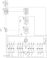
- FIG. 1 is an exemplary diagram showing the architecture of an energy storage system according to the present disclosure.
- the energy storage system 1 includes a battery pack 10, a relay 20 and a power conversion system 30.
- the battery pack 10 includes a first battery module 11, a second battery module 12, a busbar 13 and a busbar diagnosis apparatus 100.
- a series circuit of the first battery module 11, the busbar 13 and the second battery module 12 is electrically connectable to the power conversion system 30 through the relay 20.
- the first battery module 11 includes a plurality of battery cells C 1 ⁇ C m connected in series, where m is a natural number of 2 or greater.
- the second battery module 12 includes a plurality of battery cells C m+1 ⁇ C m+n connected in series, where n is a natural number of 2 or greater.
- the plurality of battery cells C 1 ⁇ C m and the plurality of battery cells C m+1 ⁇ C m+n . may be manufactured with the same electrochemical specification.
- the reference symbol 'C' is used to refer to the battery cell.
- the battery cell C is not limited to a particular type and may include any type of battery cell that can be repeatedly recharged, for example, a lithium ion cell.
- each of the plurality of battery cells C 1 ⁇ C m has a positive electrode lead and a negative electrode lead, and the positive electrode lead of one (for example, C 1 ) of two adjacent battery cells (for example, C 1 , C 2 ) and the negative electrode lead of the other (for example, C 2 ) may be joined together through welding. Accordingly, a series connection structure from the negative electrode lead of the battery cell C 1 to the positive electrode lead of the battery cell C m is positioned in the first battery module 11.
- each of the plurality of battery cells C m+1 ⁇ C m+n has a positive electrode lead and a negative electrode lead, and the positive electrode lead of one (for example, C m+1 ) of two adjacent battery cells (for example, C m+1 , C m+2 ) and the negative electrode lead of the other (for example, C m+2 ) are joined together through welding. Accordingly, a series connection structure from the negative electrode lead of the battery cell C m+1 to the positive electrode lead of the battery cell C m+n is positioned in the second battery module 12.
- the positive electrode lead and the negative electrode lead of the battery cell C may be also referred to as a 'positive electrode' and a 'negative electrode', respectively.
- a plus terminal of the first battery module 11 is connected to a minus terminal of the second battery module 12 through the busbar 13.
- one end of the busbar 13 is fixed and coupled to the plus terminal of the first battery module 11 through a bolt
- the other end of the busbar 13 is fixed and coupled to the minus terminal of the second battery module 12 through a bolt.
- each battery module 11, 12 an electrical location of lower potential may be referred to as 'downstream' and the opposite location may be referred to as 'upstream'.
- the battery cell C m is disposed on the most upstream of the first battery module 11, and the battery cell C m+1 is disposed on the most downstream of the second battery module 12.
- the plus terminal of the first battery module 11 may have the same potential as the positive electrode of the battery cell C m
- the minus terminal of the second battery module 12 may have the same potential as the negative electrode of the battery cell C m+1 .
- the battery cell C x is disposed on the upstream of the battery cell C x-1 , and the battery cell C x-1 is disposed on the downstream of the battery cell C x .
- the relay 20 is installed on a power line provided as a current path for the charge/discharge of the battery pack 10. While the relay 20 is on, power may be transferred from any one of the battery pack 10 and the power conversion system 30 to the other.
- the relay 20 may include at least one of well-known switching devices, for example, a mechanical contactor and a Field Effect Transistor (FET).
- FET Field Effect Transistor
- a control circuit 140 may perform on/off control of the relay 20 according to the diagnosis result of the busbar 13 as described below.
- the power conversion system 30 is operably coupled to the busbar diagnosis apparatus 100 through a high-level controller 2.
- the power conversion system 30 may produce DC power for the charge of the battery pack 10 from AC power supplied by an electrical grid 40.
- the power conversion system 30 may produce AC power from DC power from the battery pack 10.
- the busbar diagnosis apparatus 100 is provided to monitor a fault of the busbar 13.
- the fault of the busbar 13 refers to an increase in the total resistance across the busbar 13 above an allowed value from a predetermined initial value due to at least one of (i) a defect (for example, crack) of the busbar 13 itself, (ii) failed coupling to the plus terminal of the first battery module 11 and (iii) failed coupling to the minus terminal of the second battery module 12.
- the busbar diagnosis apparatus 100 includes a voltage sensing channel 110, a battery monitoring circuit 120, a bypass device 130 and the control circuit 140.
- the busbar diagnosis apparatus 100 may further include at least one of a shunt resistor 150 or a communication circuit 160.
- the battery monitoring circuit 120 includes a plurality of voltage sensing pins P 0 ⁇ P m+n+1 .
- the plurality of voltage sensing pins P 0 ⁇ P m+n+1 is provided electrically connectably to the positive electrode lead and the negative electrode lead of each of the plurality of battery cells C 1 ⁇ C m+n through the voltage sensing channel 110.
- the battery monitoring circuit 120 may be implemented in hardware using application specific integrated circuits (ASICs). For the battery monitoring circuit 120, for example, BQ76940 may be used.
- the voltage sensing channel 110 may include a plurality of voltage sensing lines L 0 ⁇ L m+n+1 .
- Each of the plurality of voltage sensing lines L 0 ⁇ L m+n+1 may include a protection resistor R having a predetermined resistance.
- the protection resistor R is provided to prevent an overcurrent through the voltage sensing line in which the protection resistor R is included.
- One end and the other end of the voltage sensing line L 0 are connected to the negative electrode of the battery cell C 1 and the voltage sensing pin P 0 of the battery monitoring circuit 120, respectively.
- one end and the other end of the voltage sensing line Li are connected to the positive electrode of the battery cell C i and the voltage sensing pin Pi of the battery monitoring circuit 120, respectively.
- One end and the other end of the voltage sensing line L m+1 are connected to the negative electrode of the battery cell C m+1 and the voltage sensing pin P m+1 of the battery monitoring circuit 120, respectively.
- one end and the other end of the voltage sensing line L j are connected to the positive electrode of the battery cell C j and the voltage sensing pin P j of the battery monitoring circuit 120, respectively.
- the battery monitoring circuit 120 detects a voltage across each of the plurality of battery cells C 1 ⁇ C m+n using a potential difference of every two adjacent voltage sensing pins among the plurality of voltage sensing pins P 0 ⁇ P m+n+1 .
- the battery monitoring circuit 120 may detect the potential difference between two adjacent voltage sensing pins P m-1 , P m as the voltage of the battery cell C m . In another example, the battery monitoring circuit 120 may detect the potential difference between two adjacent voltage sensing pins P m+1 , P m+2 as the voltage of the battery cell C m+1 .
- the control circuit 140 may collect a voltage signal from the battery monitoring circuit 120 at a set time interval (for example, 0.001 sec), and determine a value indicating the voltage of each of the plurality of battery cells C 1 ⁇ C m+n through analog-digital conversion.
- the bypass device 130 is connected to the busbar 13 in parallel through the pair of voltage sensing lines L m , L m+1 . Specifically, one end and the other end of the bypass device 130 are connected to the pair of voltage sensing pins P m , P m+1 , respectively. Accordingly, a closed loop including the bypass device 130, the voltage sensing pin P m+1 , the voltage sensing line L m+1 , the busbar 13, the voltage sensing line L m and the voltage sensing pin P m is formed. While a predetermined condition (for example, a discharge mode of the battery pack) for the bypass device 130 is satisfied, the two voltage sensing pins P m , P m+1 are electrically connected through the bypass device 130. In contrast, while the predetermined condition for the bypass device 130 is unsatisfied, the current path between the two voltage sensing pins P m , P m+1 through the bypass device 130 is blocked.
- a predetermined condition for example, a discharge mode of the battery pack
- FIG. 1 shows the bypass device 130 positioned outside of the battery monitoring circuit 120
- the bypass device 130 may be integrated in the battery monitoring circuit 120 as a component of the battery monitoring circuit 120.
- the resistance of the busbar 13 is much smaller than the resistance of the protection resistor R included in the two voltage sensing lines L m , L m+1 , and thus all or most of electric currents flowing through the battery pack 10 passes through the busbar 13 and only an electric current of 0 A or a negligibly small amount in the bypass device 130.
- the control circuit 140 is operably coupled to the relay 20, the battery monitoring circuit 120, the shunt resistor 150 and/or the communication circuit 160.
- the control circuit 140 may be implemented in hardware using at least one of digital signal processors (DSPs), digital signal processing devices (DSPDs), programmable logic devices (PLDs), field programmable gate arrays (FPGAs), microprocessors or electrical units for performing the other functions.
- DSPs digital signal processors
- DSPDs digital signal processing devices
- PLDs programmable logic devices
- FPGAs field programmable gate arrays
- microprocessors or electrical units for performing the other functions.
- the control circuit 140 may have a memory embedded therein.
- the memory may pre-store programs and data necessary to perform battery management methods according to embodiments as described below.
- the memory may include, for example, at least one type of storage medium of flash memory type, hard disk type, Solid State Disk (SSD) type, Silicon Disk Drive (SDD) type, multimedia card micro type, random access memory (RAM), static random access memory (SRAM), read-only memory (ROM), electrically erasable programmable read-only memory (EEPROM) or programmable read-only memory (PROM).
- the shunt resistor 150 is electrically connected in series to the series circuit of the first battery module 11, the busbar 13 and the second battery module 12 through the power line.
- the battery monitoring circuit 120 is connected to one end and the other end of the shunt resistor 150 through a pair of current sensing pins, respectively.
- the battery monitoring circuit 120 is configured to detect the electric current flowing through the battery pack 10 based on a potential difference between the pair of current sensing pins, and output a current signal indicating the detected electric current to the control circuit 140.
- the communication circuit 160 may be coupled to the high-level controller 2 of the energy storage system 1 to enable communication between them.
- the communication circuit 160 may transmit a message from the high-level controller 2 to the control circuit 140 and a message from the control circuit 140 to the high-level controller 2.
- the message from the control circuit 140 may include information for notifying a fault in the busbar 13 and/or voltage of the battery cell C.
- a wired network such as local area network (LAN), controller area network (CAN) and daisy chain and/or a near field wireless network such as Bluetooth, Zigbee and WiFi may be used.
- the communication circuit 160 may include an output device (for example, a display, a speaker) to provide the information received from the control circuit 140 and/or the high-level controller 2 in a recognizable format.
- the high-level controller 2 may control the power conversion system 30 based on the information collected through the communication with the busbar diagnosis apparatus 100.
- FIG. 2 is a diagram for reference in describing a relationship between a fault condition of the busbar shown in FIG. 1 and a voltage detection error of the battery cell.
- a diode used for the bypass device 130 is shown by way of illustration.
- the anode and the cathode of the diode may be connected to the voltage sensing pin P m and the voltage sensing pin P m+1 , respectively.
- a voltage across the busbar 13 is applied to the diode as a forward voltage during the discharge of the battery pack 10, and the diode turns on (conducts the electric current). That is, the diode allows the electric current to flow while the battery pack 10 is in the discharge mode, and while the diode conducts the electric current, the current path parallel to the busbar 13 is formed.
- the discharge mode refers to a mode in which power is supplied from the battery pack 10 to the power conversion system by the flow of the discharge current through the first battery module 11 and the second battery module 12.
- the total resistance of the busbar 13 is the sum of (i) the resistance of the busbar 13 itself, (ii) the contact resistance at the connection portion Q A between one end of the busbar 13 and the plus terminal of the first battery module 11 and (iii) the contact resistance at the connection portion Q B between the other end of the busbar 13 and the minus terminal of the second battery module 12.
- the electric current I P of the battery pack 10 is equal to the sum of the electric current I A flowing through the busbar 13 and the electric current I B flowing through the bypass device 130.
- the bypass device 130 turns on (conducts the electric current)
- a ratio I B /I A of the electric current I B flowing through the bypass device 130 to the electric current I A flowing through the busbar 13 is larger according to a resistance ratio between the busbar 13 and the bypass path.
- the bypass path is a series connection path of the voltage sensing line L m , the bypass device 130 and the voltage sensing line L m+1 . That is, the flow of the electric current I B through the bypass device 130 refers to the flow of the electric current I B through the pair of voltage sensing lines L m , L m+1 .
- the voltage of the battery cell C m detected by the battery monitoring circuit 120 reduces by as much as the voltage drop V D at the voltage sensing line L m from the actual voltage of the battery cell C m .
- the voltage of the battery cell C m+1 detected by the battery monitoring circuit 120 also reduces by as much as the voltage drop V D at the voltage sensing line L m+1 from the actual voltage of the battery cell C m+1 . That is, an error occurs in the detection result of the voltage of the battery cell C m disposed on the most upstream of the first battery module 11 and the voltage of the battery cell C m+1 disposed on the most downstream of the second battery module 12.
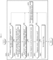
- FIG. 3 is an exemplary flowchart of a busbar diagnosis method according to the present disclosure
- FIG. 4 is a schematic flowchart of a fault detection process according to a first embodiment for performing the step S320 of FIG. 3
- FIG. 5 is a schematic flowchart of a fault detection process according to a second embodiment for performing the step S320 of FIG. 3 .
- the method of FIGS. 3 to 5 may be repeatedly performed by the busbar diagnosis apparatus 100 in a periodic manner at each predetermined diagnosis time.
- the diagnosis time may be equal to the above-described predetermined time or may be preset to the integer multiple of the predetermined time.
- the battery monitoring circuit 120 detects the voltage of each of the plurality of battery cells C 1 ⁇ C m of the first battery module 11 and the plurality of battery cells C m+1 ⁇ C m+n of the second battery module 12 using the potential difference of every two adjacent voltage sensing pins (for example, P 0 , P 1 ) among the plurality of voltage sensing pins P 0 ⁇ P m+n+1 .
- the control circuit 140 may collect an analog signal indicating the voltage of each of the plurality of battery cells C 1 ⁇ C m+n detected by the battery monitoring circuit 120, convert the collected analog signal to a digital signal, and record it in the memory as the latest value in time series indicating a voltage history.
- the time series indicating the voltage history of the battery cell C includes a value of the voltage detected in the previous cycle and a value of the voltage detected in the present cycle.
- the battery monitoring circuit 120 may further detect the electric current of the battery pack 10 using the pair of current sensing pins. That is, the control circuit 140 may collect an analog signal indicating the electric current of the battery pack 10, convert the collected analog signal to a digital signal, and record it in the memory as the latest value in time series indicating a current history.
- step S320 the control circuit 140 diagnoses the busbar 13 based on the voltage history of each of the plurality of battery cells C 1 ⁇ C m of the first battery module 11 and the plurality of battery cells C m+1 ⁇ C m+n of the second battery module 12, detected by the battery monitoring circuit 120.
- the step S320 includes steps S410 ⁇ S470.
- the control circuit 140 determines if the battery pack 10 is kept in the discharge mode for a set time (for example, 1 sec) or more based on the electric current detected by the battery monitoring circuit 120. That is, the control circuit 140 records a time series indicating a history of changes of the electric current of the battery pack 10 in the memory, and determines if the battery pack 10 is being continuously discharged for the set time or more based on the recorded time series of the electric current.
- the control circuit 140 determines that a value of the step S410 is "YES”, and otherwise, determines that the value of the step S410 is "NO”.
- step S420 is performed.
- step S470 is performed.
- the control circuit 140 determines an average voltage of the plurality of battery cells C 1 ⁇ C m of the first battery module 11 and the plurality of battery cells C m+1 ⁇ C m+n of the second battery module 12.
- the average voltage in the step S420 may be determined by the following Equation 1 or 2.
- Equation 1 t is the present time
- V y [t] is the voltage of the battery cell C y at the present time, detected by the battery monitoring device
- V AV [t] is the average voltage at the present time. Equation 2 is different from Equation 1 since the average voltage is calculated with the exclusion of the voltages V m [t], V m+1 [t] of the two battery cells C m , C m+1 relying on the condition of the busbar 13.
- the control circuit 140 determines if both (i) a difference V AV [t]-V m [t] between the voltage V m [t] of the battery cell C m disposed on the most upstream of the first battery module 11 and the average voltage V AV [t] and (ii) a difference V AV [t]-V m+1 [t] between the voltage V m+1 [t] of the battery cell C m+1 disposed on the most downstream of the second battery module 12 and the average voltage V AV [t] are larger than a reference voltage difference.
- the reference voltage difference (for example, 0.3 V) is preset to be larger than V AV [t]-V m [t] and V AV [t]-V m+1 [t], taking into account the ability of the battery monitoring circuit 120 to divide the voltage.
- a value of the step S430 being "YES” indicates that the likelihood that the busbar 13 is in a fault condition is equal to or larger than the reference value.
- the step S440 is performed.
- the step S470 is performed.
- the control circuit 140 increases a diagnosis count by a predetermined value (for example, 1).
- the diagnosis count indicates the number of times the value of the step S430 is continuously determined as "YES".
- the control circuit 140 determines if the diagnosis count is equal to or larger than a reference count (for example, 3). When a value of the step S450 is "YES", the step S460 is performed.
- the control circuit 140 sets a diagnosis flag indicating that the busbar 13 is in a fault condition.
- the control circuit 140 may perform a predetermined protection operation in response to the diagnosis flag being set.
- the control circuit 140 may transmit a fault message indicating that the busbar 13 is in a fault condition to the high-level controller 2.
- the high-level controller 2 may stop the power conversion system 30 in response to the fault message.
- the control circuit 140 may turn off the relay 20.
- the control circuit 140 may set each of the detected voltage values V m [t], V m+1 [t] of the battery cells C m , C m+1 to be equal to the average voltage V AV [t] of the plurality of battery cells C 1 ⁇ C m+n .
- control circuit 140 sets the diagnosis count to the initial value (for example, 0) less than the reference count.
- the step S320 includes steps S510 ⁇ S550.
- the control circuit 140 determines if the battery pack 10 is switched from a charge mode or a rest mode to the discharge mode based on the electric current detected by the battery monitoring circuit 120.
- the rest mode refers to a mode in which the relay 20 is off or the power conversion system 30 stops and thus both the charge current and the discharge current do not flow through the first battery module 11 and the second battery module 12.
- the charge mode refers to a mode in which power is supplied from the power conversion system to the battery pack 10 and the charge current flows through the first battery module 11 and the second battery module 12.
- the control circuit 140 records a time series indicating a history of changes of the electric current of the battery pack 10 in the memory, and when the electric current at the diagnosis time earlier than the present time is recorded as 0 or a positive value based on the recorded time series of the electric current, and the electric current at the present time is recorded as a negative value, the control circuit 140 may determine a value of the step S510 as "YES”. If not so, the value of the step S510 may be determined as "NO". When the value of the step S510 is "YES", the step S520 is performed.
- the control circuit 140 determines a voltage drop of the battery cell C m disposed on the most upstream of the first battery module 11, a voltage drop of the battery cell C m+1 disposed on the most downstream of the second battery module 12 and an average voltage drop of the plurality of battery cells C 1 ⁇ C m of the first battery module 11 and the plurality of battery cells C m+1 ⁇ C m+n of the second battery module 12 over the diagnosis time.
- the average voltage drop in the step S520 may be determined by the following Equation 3 or 4.
- Equations 3 and 4 t is the present time, ⁇ V y [t] is the voltage drop of the battery cell C y , and ⁇ V AV [t] is the average voltage drop. ⁇ V y [t] is equal to V y [t-t D ]-V y [t], and t D is the diagnosis time. That is, V y [t-t D ] may be the voltage of the battery cell C y detected during the operation of the battery pack 10 in the rest mode or the charge mode, and V y [t] may be the voltage of the battery cell C y detected for the first time after the switch of the battery pack 10 from the rest mode or the charge mode to the discharge mode.
- Equation 4 is different from Equation 3 since the average voltage drop is calculated with the exclusion of the voltage drop ⁇ V m [t], ⁇ V m+1 [t] of the two battery cells C m , C m+1 relying on the condition of the busbar 13.
- the control circuit 140 determines a reference voltage drop by multiplying a change in electric current over the diagnosis time by a predetermined conversion coefficient.
- the change in electric current may be equal to I P [t-t D ]-I P [t].
- I P [t-to] may be the electric current of the battery pack 10 detected during the operation of the battery pack 10 in the rest mode or the charge mode, and I P [t] may be the electric current of the battery pack 10 detected for the first time after the switch of the battery pack 10 from the rest mode or the charge mode to the discharge mode.
- the conversion coefficient may be a preset value, taking into account the internal resistance range when the battery cell C is in normal condition.
- the control circuit 140 determines if both (i) a difference ⁇ V m [t]- ⁇ V AV [t] between the voltage drop ⁇ V m [t] of the battery cell C m disposed on the most upstream of the first battery module 11 and the average voltage drop ⁇ V AV [t] and (ii) a difference ⁇ V m+i [t]- ⁇ V AV [t] between the voltage drop ⁇ V m+1 [t] of the battery cell C m+1 disposed on the most downstream of the second battery module 12 and the average voltage drop ⁇ V AV [t] are larger than the reference voltage drop.
- the value of the step S540 being "YES" indicates that the busbar 13 is in a fault condition.
- the step S550 is performed.
- the control circuit 140 sets a diagnosis flag indicating that the busbar 13 is in a fault condition.
- the control circuit 140 may perform a predetermined protection operation in response to the diagnosis flag being set.
- the control circuit 140 may transmit a fault message indicating that the busbar 13 is in a fault condition to the high-level controller 2.
- the high-level controller 2 may stop the power conversion system 30 in response to the fault message.
- the control circuit 140 may turn off the relay 20.
Landscapes
- General Physics & Mathematics (AREA)
- Physics & Mathematics (AREA)
- Engineering & Computer Science (AREA)
- General Chemical & Material Sciences (AREA)
- Chemical Kinetics & Catalysis (AREA)
- Electrochemistry (AREA)
- Chemical & Material Sciences (AREA)
- Manufacturing & Machinery (AREA)
- Power Engineering (AREA)
- Microelectronics & Electronic Packaging (AREA)
- Charge And Discharge Circuits For Batteries Or The Like (AREA)
- Secondary Cells (AREA)
- Testing Electric Properties And Detecting Electric Faults (AREA)
Abstract
Description
- The present application claims the benefit of
Korean Patent Application No. 10-2021-0008928 filed on January 21, 2021 - The present disclosure relates to fault diagnosis of a busbar used to connect two battery modules in series.
- Recently, there has been a rapid increase in the demand for portable electronic products such as laptop computers, video cameras and mobile phones, and with the extensive development of electric vehicles, accumulators for energy storage, robots and satellites, many studies are being made on high performance batteries that can be recharged repeatedly.
- Currently, commercially available batteries include nickel-cadmium batteries, nickel-hydrogen batteries, nickel-zinc batteries, lithium batteries and the like, and among them, lithium batteries have little or no memory effect, and thus they are gaining more attention than nickel-based batteries for their advantages that recharging can be done whenever it is convenient, the self-discharge rate is very low and the energy density is high.
- Recently, to provide high voltage, there is a growing demand for a battery pack including two or more battery modules connected in series through a busbar, each battery module including a plurality of battery cells connected in series.
- However, a fault may occur in the busbar due to external impacts or aging of the busbar itself. When the busbar is faulty, the safety of the battery pack becomes low, so there is a need for an approach to accurate fault diagnosis of the busbar.
-
Patent Literature 1 discloses fault detection of a busbar based on a voltage across a busbar itself or a voltage across an assembly of battery cells and busbars connected in series. However, the voltage measurement of the busbar independent of voltage measurement of the battery cell is inefficient.
(Patent Literature 1)Korean Patent Publication No. 10-2012-0080315 (published on July 17, 2012 - The present disclosure is designed to solve the above-described problem, and therefore the present disclosure is directed to providing a busbar diagnosis apparatus, a battery pack, an energy storage system and a busbar diagnosis method for fault diagnosis of a busbar based on voltage history of two battery cells, each connected to each of two ends of the busbar without a procedure of measuring the voltage of the busbar.
- These and other objects and advantages of the present disclosure may be understood by the following description and will be apparent from an embodiment of the present disclosure. In addition, it will be readily understood that the objects and advantages of the present disclosure may be realized by the means set forth in the appended claims and a combination thereof.
- A busbar diagnosis apparatus according to an aspect of the present disclosure is provided for a battery pack including a busbar connected between a plus terminal of a first battery module including a plurality of battery cells connected in series and a minus terminal of a second battery module including a plurality of battery cells connected in series. The busbar diagnosis apparatus includes a battery monitoring circuit including a plurality of voltage sensing pins, and configured to detect a voltage of each of the plurality of battery cells of the first battery module and the plurality of battery cells of the second battery module using a potential difference of every two adjacent voltage sensing pins; a voltage sensing channel including a plurality of voltage sensing lines connecting a positive electrode and a negative electrode of each of the plurality of battery cells of the first battery module and the plurality of battery cells of the second battery module to the plurality of voltage sensing pins; a bypass unit connected to the busbar through a first voltage sensing pin and a second voltage sensing pin among the plurality of voltage sensing pins, wherein the first voltage sensing pin is connected to the positive electrode of the battery cell disposed on the most upstream of the first battery module through one of the plurality of voltage sensing lines and the second voltage sensing pin is connected to the negative electrode of the battery cell disposed on the most downstream of the second battery module through the other voltage sensing line among the plurality of voltage sensing lines; and a control circuit configured to diagnose the busbar based on a voltage history of each of the plurality of battery cells of the first battery module and the plurality of battery cells of the second battery module, detected by the battery monitoring circuit.
- The bypass unit may include a diode. An anode and a cathode of the diode may be connected to the first voltage sensing pin and the second voltage sensing pin, respectively.
- Each voltage sensing line may include a protection resistor having a predetermined resistance value.
- The battery monitoring circuit may further include a pair of current sensing pins connected to a current path of the battery pack. The battery monitoring circuit may be configured to detect an electric current flowing through the current path using a potential difference between the pair of current sensing pins.
- When it is determined that the battery pack is kept in a discharge mode for a set time or more, the control circuit may be configured to determine an average voltage of the plurality of battery cells of the first battery module and the plurality of battery cells of the second battery module at each predetermined diagnosis time, increase a diagnosis count by a predetermined value when both a difference between the voltage of the battery cell disposed on the most upstream of the first battery module and the average voltage and a difference between the voltage of the battery cell disposed on the most downstream of the second battery module and the average voltage are larger than a reference voltage difference, and set a diagnosis flag indicating that the busbar is in a fault condition when the increased diagnosis count is equal to or larger than a reference count.
- The control circuit may be configured to set the diagnosis count to be equal to an initial value less than the reference count when at least one of the difference between the voltage of the battery cell disposed on the most upstream of the first battery module and the average voltage or the difference between the voltage of the battery cell disposed on the most downstream of the second battery module and the average voltage is equal to or smaller than the reference voltage difference.
- When it is determined that the battery pack is switched from a rest mode or a charge mode to a discharge mode, the control circuit may be configured to determine a voltage drop of the battery cell disposed on the most upstream of the first battery module, a voltage drop of the battery cell disposed on the most downstream of the second battery module and an average voltage drop of the plurality of battery cells of the first battery module and the plurality of battery cells of the second battery module, over the diagnosis time, and set a diagnosis flag indicating that the busbar is in a fault condition when both a difference between the voltage drop of the battery cell disposed on the most upstream of the first battery module and the average voltage drop and a difference between the voltage drop of the battery cell disposed on the most downstream of the second battery module and the average voltage drop are larger than a reference voltage drop.
- The control circuit may be configured to determine the reference voltage drop by multiplying a change in electric current over the diagnosis time by a predetermined conversion coefficient when it is determined that the battery pack is switched from a rest mode or a charge mode to a discharge mode.
- A battery pack according to another aspect of the present disclosure includes the busbar diagnosis apparatus.
- An energy storage system according to still another aspect of the present disclosure includes the battery pack.
- A busbar diagnosis method according to yet another aspect of the present disclosure is provided to be executable by the busbar diagnosis apparatus. The busbar diagnosis method includes detecting, by the battery monitoring circuit, a voltage of each of the plurality of battery cells of the first battery module and the plurality of battery cells of the second battery module using a potential difference between every two adjacent voltage sensing pins among the plurality of voltage sensing pins; and diagnosing, by the control circuit, the busbar based on a voltage history of each of the plurality of battery cells of the first battery module and the plurality of battery cells of the second battery module, detected by the battery monitoring circuit.
- According to at least one of the embodiments of the present disclosure, it is possible to achieve fault diagnosis of a busbar based on the voltage history of two battery cells, each connected to each of two ends of the busbar without a procedure of measuring the voltage of the busbar.
- According to at least one of the embodiments of the present disclosure, it is possible to achieve a more accurate fault diagnosis of a busbar by adjusting the reference (for example, the reference voltage drop as described below) used to determine if the busbar is faulty based on the electric current of the battery pack that changes over time.
- The effects of the present disclosure are not limited to the above-mentioned effects, and these and other effects will be clearly understood by those skilled in the art from the appended claims.
- The accompanying drawings illustrate a preferred embodiment of the present disclosure, and together with the detailed description of the present disclosure as described below, serve to provide a further understanding of the technical aspects of the present disclosure, and thus the present disclosure should not be construed as being limited to the drawings.
-
FIG. 1 is an exemplary diagram showing the architecture of an energy storage system according to the present disclosure. -
FIG. 2 is a diagram for reference in describing a relationship between a fault condition of a busbar shown inFIG. 1 and a voltage detection error of a battery cell. -
FIG. 3 is an exemplary flowchart of a busbar diagnosis method according to the present disclosure. -
FIG. 4 is a schematic flowchart showing a fault detection process according to a first embodiment for performing the step S320 ofFIG. 3 . -
FIG. 5 is a schematic flowchart showing a fault detection process according to a second embodiment for performing the step S320 ofFIG. 3 . - Hereinafter, a preferred embodiment of the present disclosure will be described in detail with reference to the accompanying drawings. Prior to the description, it should be understood that the terms or words used in the specification and the appended claims should not be construed as being limited to general and dictionary meanings, but rather interpreted based on the meanings and concepts corresponding to the technical aspects of the present disclosure on the basis of the principle that the inventor is allowed to define the terms appropriately for the best explanation.
- Therefore, the embodiments described herein and the illustrations shown in the drawings are just a most preferred embodiment of the present disclosure, but not intended to fully describe the technical aspects of the present disclosure, so it should be understood that a variety of other equivalents and modifications could have been made thereto at the time that the application was filed.
- The terms including the ordinal number such as "first", "second" and the like, are used to distinguish one element from another among various elements, but not intended to limit the elements.
- Unless the context clearly indicates otherwise, it will be understood that the term "comprises" when used in this specification, specifies the presence of stated elements, but does not preclude the presence or addition of one or more other elements. Additionally, the term "control circuit" as used herein refers to a processing unit of at least one function or operation, and may be implemented by hardware and software either alone or in combination.
- In addition, throughout the specification, it will be further understood that when an element is referred to as being "connected to" another element, it can be directly connected to the other element or intervening elements may be present.
-
FIG. 1 is an exemplary diagram showing the architecture of an energy storage system according to the present disclosure. - Referring to
FIG. 1 , theenergy storage system 1 includes abattery pack 10, arelay 20 and apower conversion system 30. - The
battery pack 10 includes a first battery module 11, a second battery module 12, abusbar 13 and abusbar diagnosis apparatus 100. - A series circuit of the first battery module 11, the
busbar 13 and the second battery module 12 is electrically connectable to thepower conversion system 30 through therelay 20. - The first battery module 11 includes a plurality of battery cells C1~Cm connected in series, where m is a natural number of 2 or greater. The second battery module 12 includes a plurality of battery cells Cm+1~Cm+n connected in series, where n is a natural number of 2 or greater.
- The plurality of battery cells C1~Cm and the plurality of battery cells Cm+1~Cm+n. may be manufactured with the same electrochemical specification. Hereinafter, in describing the subject matter that is common to all the battery cells C1~Cm+n included in the
battery pack 10, the reference symbol 'C' is used to refer to the battery cell. - The battery cell C is not limited to a particular type and may include any type of battery cell that can be repeatedly recharged, for example, a lithium ion cell.
- In the first battery module 11, each of the plurality of battery cells C1~Cm has a positive electrode lead and a negative electrode lead, and the positive electrode lead of one (for example, C1) of two adjacent battery cells (for example, C1, C2) and the negative electrode lead of the other (for example, C2) may be joined together through welding. Accordingly, a series connection structure from the negative electrode lead of the battery cell C1 to the positive electrode lead of the battery cell Cm is positioned in the first battery module 11.
- In the second battery module 12, each of the plurality of battery cells Cm+1~Cm+n has a positive electrode lead and a negative electrode lead, and the positive electrode lead of one (for example, Cm+1) of two adjacent battery cells (for example, Cm+1, Cm+2) and the negative electrode lead of the other (for example, Cm+2) are joined together through welding. Accordingly, a series connection structure from the negative electrode lead of the battery cell Cm+1 to the positive electrode lead of the battery cell Cm+n is positioned in the second battery module 12.
- Hereinafter, it should be noted that the positive electrode lead and the negative electrode lead of the battery cell C may be also referred to as a 'positive electrode' and a 'negative electrode', respectively.
- A plus terminal of the first battery module 11 is connected to a minus terminal of the second battery module 12 through the
busbar 13. For example, one end of thebusbar 13 is fixed and coupled to the plus terminal of the first battery module 11 through a bolt, and the other end of thebusbar 13 is fixed and coupled to the minus terminal of the second battery module 12 through a bolt. - In each battery module 11, 12, an electrical location of lower potential may be referred to as 'downstream' and the opposite location may be referred to as 'upstream'. For example, the battery cell Cm is disposed on the most upstream of the first battery module 11, and the battery cell Cm+1 is disposed on the most downstream of the second battery module 12. The plus terminal of the first battery module 11 may have the same potential as the positive electrode of the battery cell Cm, and the minus terminal of the second battery module 12 may have the same potential as the negative electrode of the battery cell Cm+1. When x is a natural number of 2 or greater and m+n or smaller, it may be said that the battery cell Cx is disposed on the upstream of the battery cell Cx-1, and the battery cell Cx-1 is disposed on the downstream of the battery cell Cx.
- The
relay 20 is installed on a power line provided as a current path for the charge/discharge of thebattery pack 10. While therelay 20 is on, power may be transferred from any one of thebattery pack 10 and thepower conversion system 30 to the other. Therelay 20 may include at least one of well-known switching devices, for example, a mechanical contactor and a Field Effect Transistor (FET). Acontrol circuit 140 may perform on/off control of therelay 20 according to the diagnosis result of thebusbar 13 as described below. - The
power conversion system 30 is operably coupled to thebusbar diagnosis apparatus 100 through a high-level controller 2. Thepower conversion system 30 may produce DC power for the charge of thebattery pack 10 from AC power supplied by anelectrical grid 40. Thepower conversion system 30 may produce AC power from DC power from thebattery pack 10. - The
busbar diagnosis apparatus 100 is provided to monitor a fault of thebusbar 13. The fault of thebusbar 13 refers to an increase in the total resistance across thebusbar 13 above an allowed value from a predetermined initial value due to at least one of (i) a defect (for example, crack) of thebusbar 13 itself, (ii) failed coupling to the plus terminal of the first battery module 11 and (iii) failed coupling to the minus terminal of the second battery module 12. - The
busbar diagnosis apparatus 100 includes avoltage sensing channel 110, abattery monitoring circuit 120, abypass device 130 and thecontrol circuit 140. Thebusbar diagnosis apparatus 100 may further include at least one of ashunt resistor 150 or acommunication circuit 160. - The
battery monitoring circuit 120 includes a plurality of voltage sensing pins P0~Pm+n+1. The plurality of voltage sensing pins P0~Pm+n+1 is provided electrically connectably to the positive electrode lead and the negative electrode lead of each of the plurality of battery cells C1~Cm+n through thevoltage sensing channel 110. Thebattery monitoring circuit 120 may be implemented in hardware using application specific integrated circuits (ASICs). For thebattery monitoring circuit 120, for example, BQ76940 may be used. - The
voltage sensing channel 110 may include a plurality of voltage sensing lines L0~Lm+n+1. Each of the plurality of voltage sensing lines L0~Lm+n+1 may include a protection resistor R having a predetermined resistance. The protection resistor R is provided to prevent an overcurrent through the voltage sensing line in which the protection resistor R is included. - One end and the other end of the voltage sensing line L0 are connected to the negative electrode of the battery cell C1 and the voltage sensing pin P0 of the
battery monitoring circuit 120, respectively. - When i is a natural number of m or smaller, one end and the other end of the voltage sensing line Li are connected to the positive electrode of the battery cell Ci and the voltage sensing pin Pi of the
battery monitoring circuit 120, respectively. - One end and the other end of the voltage sensing line Lm+1 are connected to the negative electrode of the battery cell Cm+1 and the voltage sensing pin Pm+1 of the
battery monitoring circuit 120, respectively. - When j is a natural number of m+2 or greater and m+n+1 or smaller, one end and the other end of the voltage sensing line Lj are connected to the positive electrode of the battery cell Cj and the voltage sensing pin Pj of the
battery monitoring circuit 120, respectively. - The
battery monitoring circuit 120 detects a voltage across each of the plurality of battery cells C1~Cm+n using a potential difference of every two adjacent voltage sensing pins among the plurality of voltage sensing pins P0~Pm+n+1. - That is, when i is a natural number of m or smaller and j is a natural number of m+2 or greater and m+n+1 or smaller, the potential difference between two voltage sensing pins Pi-1, Pi is detected as the voltage of the battery cell Ci, and the potential difference between two voltage sensing pins Pj-1, Pj is detected as the voltage of the battery cell Cj-1. In an example, the
battery monitoring circuit 120 may detect the potential difference between two adjacent voltage sensing pins Pm-1, Pm as the voltage of the battery cell Cm. In another example, thebattery monitoring circuit 120 may detect the potential difference between two adjacent voltage sensing pins Pm+1, Pm+2 as the voltage of the battery cell Cm+1. - The
control circuit 140 may collect a voltage signal from thebattery monitoring circuit 120 at a set time interval (for example, 0.001 sec), and determine a value indicating the voltage of each of the plurality of battery cells C1~Cm+n through analog-digital conversion. - The
bypass device 130 is connected to thebusbar 13 in parallel through the pair of voltage sensing lines Lm, Lm+1. Specifically, one end and the other end of thebypass device 130 are connected to the pair of voltage sensing pins Pm, Pm+1, respectively. Accordingly, a closed loop including thebypass device 130, the voltage sensing pin Pm+1, the voltage sensing line Lm+1, thebusbar 13, the voltage sensing line Lm and the voltage sensing pin Pm is formed. While a predetermined condition (for example, a discharge mode of the battery pack) for thebypass device 130 is satisfied, the two voltage sensing pins Pm, Pm+1 are electrically connected through thebypass device 130. In contrast, while the predetermined condition for thebypass device 130 is unsatisfied, the current path between the two voltage sensing pins Pm, Pm+1 through thebypass device 130 is blocked. - Although
FIG. 1 shows thebypass device 130 positioned outside of thebattery monitoring circuit 120, alternatively, thebypass device 130 may be integrated in thebattery monitoring circuit 120 as a component of thebattery monitoring circuit 120. - When the
busbar 13 is in normal condition, the resistance of thebusbar 13 is much smaller than the resistance of the protection resistor R included in the two voltage sensing lines Lm, Lm+1, and thus all or most of electric currents flowing through thebattery pack 10 passes through thebusbar 13 and only an electric current of 0 A or a negligibly small amount in thebypass device 130. - In contrast, when the
busbar 13 is in a fault condition, (i) the resistance of thebusbar 13 itself, (ii) the contact resistance between one end of thebusbar 13 and the plus terminal of the first battery module 11 and/or (iii) the contact resistance between the other end of thebusbar 13 and the minus terminal of the second battery module 12 increases from the normal level. Accordingly, as the fault condition of thebusbar 13 gets severe, there is a gradual increase in the amount of electric current passing through thebypass device 130 among the total amount of electric current flowing through thebattery pack 10. - The
control circuit 140 is operably coupled to therelay 20, thebattery monitoring circuit 120, theshunt resistor 150 and/or thecommunication circuit 160. - The
control circuit 140 may be implemented in hardware using at least one of digital signal processors (DSPs), digital signal processing devices (DSPDs), programmable logic devices (PLDs), field programmable gate arrays (FPGAs), microprocessors or electrical units for performing the other functions. - The
control circuit 140 may have a memory embedded therein. The memory may pre-store programs and data necessary to perform battery management methods according to embodiments as described below. The memory may include, for example, at least one type of storage medium of flash memory type, hard disk type, Solid State Disk (SSD) type, Silicon Disk Drive (SDD) type, multimedia card micro type, random access memory (RAM), static random access memory (SRAM), read-only memory (ROM), electrically erasable programmable read-only memory (EEPROM) or programmable read-only memory (PROM). - The
shunt resistor 150 is electrically connected in series to the series circuit of the first battery module 11, thebusbar 13 and the second battery module 12 through the power line. Thebattery monitoring circuit 120 is connected to one end and the other end of theshunt resistor 150 through a pair of current sensing pins, respectively. Thebattery monitoring circuit 120 is configured to detect the electric current flowing through thebattery pack 10 based on a potential difference between the pair of current sensing pins, and output a current signal indicating the detected electric current to thecontrol circuit 140. - The
communication circuit 160 may be coupled to the high-level controller 2 of theenergy storage system 1 to enable communication between them. Thecommunication circuit 160 may transmit a message from the high-level controller 2 to thecontrol circuit 140 and a message from thecontrol circuit 140 to the high-level controller 2. The message from thecontrol circuit 140 may include information for notifying a fault in thebusbar 13 and/or voltage of the battery cell C. For the communication between thecommunication circuit 160 and the high-level controller 2, for example, a wired network such as local area network (LAN), controller area network (CAN) and daisy chain and/or a near field wireless network such as Bluetooth, Zigbee and WiFi may be used. Thecommunication circuit 160 may include an output device (for example, a display, a speaker) to provide the information received from thecontrol circuit 140 and/or the high-level controller 2 in a recognizable format. The high-level controller 2 may control thepower conversion system 30 based on the information collected through the communication with thebusbar diagnosis apparatus 100. -
FIG. 2 is a diagram for reference in describing a relationship between a fault condition of the busbar shown inFIG. 1 and a voltage detection error of the battery cell. - In
FIG. 2 , a diode used for thebypass device 130 is shown by way of illustration. The anode and the cathode of the diode may be connected to the voltage sensing pin Pm and the voltage sensing pin Pm+1, respectively. In this case, a voltage across thebusbar 13 is applied to the diode as a forward voltage during the discharge of thebattery pack 10, and the diode turns on (conducts the electric current). That is, the diode allows the electric current to flow while thebattery pack 10 is in the discharge mode, and while the diode conducts the electric current, the current path parallel to thebusbar 13 is formed. The discharge mode refers to a mode in which power is supplied from thebattery pack 10 to the power conversion system by the flow of the discharge current through the first battery module 11 and the second battery module 12. - Referring to
FIG. 2 , when thebusbar 13 is in a fault condition by some reasons, the total resistance of thebusbar 13 increases above the allowed value from the initial value as described above. The total resistance of thebusbar 13 is the sum of (i) the resistance of thebusbar 13 itself, (ii) the contact resistance at the connection portion QA between one end of thebusbar 13 and the plus terminal of the first battery module 11 and (iii) the contact resistance at the connection portion QB between the other end of thebusbar 13 and the minus terminal of the second battery module 12. - In this case, the electric current IP of the
battery pack 10 is equal to the sum of the electric current IA flowing through thebusbar 13 and the electric current IB flowing through thebypass device 130. When thebypass device 130 turns on (conducts the electric current), as the total resistance of thebusbar 13 is larger, a ratio IB/IA of the electric current IB flowing through thebypass device 130 to the electric current IA flowing through thebusbar 13 is larger according to a resistance ratio between thebusbar 13 and the bypass path. The bypass path is a series connection path of the voltage sensing line Lm, thebypass device 130 and the voltage sensing line Lm+1. That is, the flow of the electric current IB through thebypass device 130 refers to the flow of the electric current IB through the pair of voltage sensing lines Lm, Lm+1. - When the electric current IB flows through the voltage sensing line Lm, a voltage drop VD corresponding to multiplication of the electric current IB by the resistance of the protection resistor R occurs between the positive electrode of the battery cell Cm and the voltage sensing pin Pm. Additionally, when the electric current IB flows through the voltage sensing line Lm+1, a voltage drop VD corresponding to multiplication of the electric current IB by the resistance of the protection resistor R occurs between the voltage sensing pin Pm+1 and the negative electrode of the battery cell Cm+1.
- Accordingly, the voltage of the battery cell Cm detected by the
battery monitoring circuit 120 reduces by as much as the voltage drop VD at the voltage sensing line Lm from the actual voltage of the battery cell Cm. Additionally, the voltage of the battery cell Cm+1 detected by thebattery monitoring circuit 120 also reduces by as much as the voltage drop VD at the voltage sensing line Lm+1 from the actual voltage of the battery cell Cm+1. That is, an error occurs in the detection result of the voltage of the battery cell Cm disposed on the most upstream of the first battery module 11 and the voltage of the battery cell Cm+1 disposed on the most downstream of the second battery module 12. -
FIG. 3 is an exemplary flowchart of a busbar diagnosis method according to the present disclosure,FIG. 4 is a schematic flowchart of a fault detection process according to a first embodiment for performing the step S320 ofFIG. 3 , andFIG. 5 is a schematic flowchart of a fault detection process according to a second embodiment for performing the step S320 ofFIG. 3 . The method ofFIGS. 3 to 5 may be repeatedly performed by thebusbar diagnosis apparatus 100 in a periodic manner at each predetermined diagnosis time. The diagnosis time may be equal to the above-described predetermined time or may be preset to the integer multiple of the predetermined time. - Referring to
FIGS. 1 to 3 , in step S310, thebattery monitoring circuit 120 detects the voltage of each of the plurality of battery cells C1~Cm of the first battery module 11 and the plurality of battery cells Cm+1~Cm+n of the second battery module 12 using the potential difference of every two adjacent voltage sensing pins (for example, P0, P1) among the plurality of voltage sensing pins P0~Pm+n+1. Thecontrol circuit 140 may collect an analog signal indicating the voltage of each of the plurality of battery cells C1~Cm+n detected by thebattery monitoring circuit 120, convert the collected analog signal to a digital signal, and record it in the memory as the latest value in time series indicating a voltage history. The time series indicating the voltage history of the battery cell C includes a value of the voltage detected in the previous cycle and a value of the voltage detected in the present cycle. In the step S310, thebattery monitoring circuit 120 may further detect the electric current of thebattery pack 10 using the pair of current sensing pins. That is, thecontrol circuit 140 may collect an analog signal indicating the electric current of thebattery pack 10, convert the collected analog signal to a digital signal, and record it in the memory as the latest value in time series indicating a current history. - In step S320, the
control circuit 140 diagnoses thebusbar 13 based on the voltage history of each of the plurality of battery cells C1~Cm of the first battery module 11 and the plurality of battery cells Cm+1~Cm+n of the second battery module 12, detected by thebattery monitoring circuit 120. - Referring to
FIG. 4 , the step S320 according to the first embodiment includes steps S410~S470. In the step S410, thecontrol circuit 140 determines if thebattery pack 10 is kept in the discharge mode for a set time (for example, 1 sec) or more based on the electric current detected by thebattery monitoring circuit 120. That is, thecontrol circuit 140 records a time series indicating a history of changes of the electric current of thebattery pack 10 in the memory, and determines if thebattery pack 10 is being continuously discharged for the set time or more based on the recorded time series of the electric current. For example, in case that it is programmed to record the charge current of thebattery pack 10 as a positive value and the discharge current as a negative value in the memory, when the time series of the electric current recorded in the time range from a set time earlier than the present time to the present time is recorded as a negative value, thecontrol circuit 140 determines that a value of the step S410 is "YES", and otherwise, determines that the value of the step S410 is "NO". When the value of the step S410 is "YES", step S420 is performed. When the value of the step S410 is "NO", the step S470 is performed. - In the step S420, the
control circuit 140 determines an average voltage of the plurality of battery cells C1~Cm of the first battery module 11 and the plurality of battery cells Cm+1~Cm+n of the second battery module 12. The average voltage in the step S420 may be determined by the followingEquation


- In
Equations Equation 2 is different fromEquation 1 since the average voltage is calculated with the exclusion of the voltages Vm[t], Vm+1[t] of the two battery cells Cm, Cm+1 relying on the condition of thebusbar 13. - In the step S430, the
control circuit 140 determines if both (i) a difference VAV[t]-Vm[t] between the voltage Vm[t] of the battery cell Cm disposed on the most upstream of the first battery module 11 and the average voltage VAV[t] and (ii) a difference VAV[t]-Vm+1[t] between the voltage Vm+1[t] of the battery cell Cm+1 disposed on the most downstream of the second battery module 12 and the average voltage VAV[t] are larger than a reference voltage difference. When thebusbar 13 and the plurality of battery cells C1~Cm+n are all in normal condition, the reference voltage difference (for example, 0.3 V) is preset to be larger than VAV[t]-Vm[t] and VAV[t]-Vm+1[t], taking into account the ability of thebattery monitoring circuit 120 to divide the voltage. A value of the step S430 being "YES" indicates that the likelihood that thebusbar 13 is in a fault condition is equal to or larger than the reference value. When the value of the step S430 is "YES", the step S440 is performed. When the value of the step S430 is "NO", the step S470 is performed. - In the step S440, the
control circuit 140 increases a diagnosis count by a predetermined value (for example, 1). The diagnosis count indicates the number of times the value of the step S430 is continuously determined as "YES". - In the step S450, the
control circuit 140 determines if the diagnosis count is equal to or larger than a reference count (for example, 3). When a value of the step S450 is "YES", the step S460 is performed. - In the step S460, the
control circuit 140 sets a diagnosis flag indicating that thebusbar 13 is in a fault condition. Thecontrol circuit 140 may perform a predetermined protection operation in response to the diagnosis flag being set. In an example, thecontrol circuit 140 may transmit a fault message indicating that thebusbar 13 is in a fault condition to the high-level controller 2. The high-level controller 2 may stop thepower conversion system 30 in response to the fault message. In another example, thecontrol circuit 140 may turn off therelay 20. In another example, thecontrol circuit 140 may set each of the detected voltage values Vm[t], Vm+1[t] of the battery cells Cm, Cm+1 to be equal to the average voltage VAV[t] of the plurality of battery cells C1~Cm+n. - In the step S470, the
control circuit 140 sets the diagnosis count to the initial value (for example, 0) less than the reference count. - Referring to
FIG. 5 , the step S320 according to the second embodiment includes steps S510~S550. In the step S510, thecontrol circuit 140 determines if thebattery pack 10 is switched from a charge mode or a rest mode to the discharge mode based on the electric current detected by thebattery monitoring circuit 120. The rest mode refers to a mode in which therelay 20 is off or thepower conversion system 30 stops and thus both the charge current and the discharge current do not flow through the first battery module 11 and the second battery module 12. The charge mode refers to a mode in which power is supplied from the power conversion system to thebattery pack 10 and the charge current flows through the first battery module 11 and the second battery module 12. - For example, the
control circuit 140 records a time series indicating a history of changes of the electric current of thebattery pack 10 in the memory, and when the electric current at the diagnosis time earlier than the present time is recorded as 0 or a positive value based on the recorded time series of the electric current, and the electric current at the present time is recorded as a negative value, thecontrol circuit 140 may determine a value of the step S510 as "YES". If not so, the value of the step S510 may be determined as "NO". When the value of the step S510 is "YES", the step S520 is performed. - In the step S520, the
control circuit 140 determines a voltage drop of the battery cell Cm disposed on the most upstream of the first battery module 11, a voltage drop of the battery cell Cm+1 disposed on the most downstream of the second battery module 12 and an average voltage drop of the plurality of battery cells C1~Cm of the first battery module 11 and the plurality of battery cells Cm+1~Cm+n of the second battery module 12 over the diagnosis time. The average voltage drop in the step S520 may be determined by the followingEquation 3 or 4.


- In
Equations 3 and 4, t is the present time, ΔVy[t] is the voltage drop of the battery cell Cy, and ΔVAV[t] is the average voltage drop. ΔVy[t] is equal to Vy[t-tD]-Vy[t], and tD is the diagnosis time. That is, Vy[t-tD] may be the voltage of the battery cell Cy detected during the operation of thebattery pack 10 in the rest mode or the charge mode, and Vy[t] may be the voltage of the battery cell Cy detected for the first time after the switch of thebattery pack 10 from the rest mode or the charge mode to the discharge mode. - Equation 4 is different from
Equation 3 since the average voltage drop is calculated with the exclusion of the voltage drop ΔVm[t], ΔVm+1[t] of the two battery cells Cm, Cm+1 relying on the condition of thebusbar 13. - In the step S530, the
control circuit 140 determines a reference voltage drop by multiplying a change in electric current over the diagnosis time by a predetermined conversion coefficient. The change in electric current may be equal to IP[t-tD]-IP[t]. IP[t-to] may be the electric current of thebattery pack 10 detected during the operation of thebattery pack 10 in the rest mode or the charge mode, and IP[t] may be the electric current of thebattery pack 10 detected for the first time after the switch of thebattery pack 10 from the rest mode or the charge mode to the discharge mode. The conversion coefficient may be a preset value, taking into account the internal resistance range when the battery cell C is in normal condition. - In the step S540, the
control circuit 140 determines if both (i) a difference ΔVm[t]-ΔVAV[t] between the voltage drop ΔVm[t] of the battery cell Cm disposed on the most upstream of the first battery module 11 and the average voltage drop ΔVAV[t] and (ii) a difference ΔVm+i[t]-ΔVAV[t] between the voltage drop ΔVm+1[t] of the battery cell Cm+1 disposed on the most downstream of the second battery module 12 and the average voltage drop ΔVAV[t] are larger than the reference voltage drop. The value of the step S540 being "YES" indicates that thebusbar 13 is in a fault condition. When the value of the step S540 is "YES", the step S550 is performed. - In the step S550, the
control circuit 140 sets a diagnosis flag indicating that thebusbar 13 is in a fault condition. Thecontrol circuit 140 may perform a predetermined protection operation in response to the diagnosis flag being set. In an example, thecontrol circuit 140 may transmit a fault message indicating that thebusbar 13 is in a fault condition to the high-level controller 2. The high-level controller 2 may stop thepower conversion system 30 in response to the fault message. In another example, thecontrol circuit 140 may turn off therelay 20. - The embodiments of the present disclosure described hereinabove are not implemented only through the apparatus and method, and may be implemented through programs that perform the functions corresponding to the configurations of the embodiments of the present disclosure or recording media having the programs recorded thereon, and such implementation may be easily achieved by those skilled in the art from the disclosure of the embodiments described above.
- While the present disclosure has been hereinabove described with regard to a limited number of embodiments and drawings, the present disclosure is not limited thereto and it is obvious to those skilled in the art that various modifications and changes may be made thereto within the technical aspects of the present disclosure and the equivalent scope of the appended claims.
- Additionally, as many substitutions, modifications and changes may be made to the present disclosure described hereinabove by those skilled in the art without departing from the technical aspects of the present disclosure, the present disclosure is not limited by the above-described embodiments and the accompanying drawings, and all or some of the embodiments may be selectively combined to allow various modifications.
(Description of Reference Numerals) 1: Energy storage system 10: Battery pack 11, 12: Battery module C: Battery cell 20: Relay 30: Power conversion system 100: Busbar diagnosis apparatus 110: Voltage sensing channel L: Voltage sensing line 120: Battery monitoring circuit P: voltage sensing pin 130: Bypass device 140: Control circuit 150: Communication circuit
Claims (11)
- A busbar diagnosis apparatus for a battery pack including a busbar connected between a plus terminal of a first battery module including a plurality of battery cells connected in series and a minus terminal of a second battery module including a plurality of battery cells connected in series, the busbar diagnosis apparatus comprising:a battery monitoring circuit including a plurality of voltage sensing pins, and configured to detect a voltage of each of the plurality of battery cells of the first battery module and the plurality of battery cells of the second battery module using a potential difference of every two adjacent voltage sensing pins;a voltage sensing channel including a plurality of voltage sensing lines connecting a positive electrode and a negative electrode of each of the plurality of battery cells of the first battery module and the plurality of battery cells of the second battery module to the plurality of voltage sensing pins;a bypass unit connected to the busbar through a first voltage sensing pin and a second voltage sensing pin among the plurality of voltage sensing pins, wherein the first voltage sensing pin is connected to the positive electrode of the battery cell disposed on the most upstream of the first battery module through one of the plurality of voltage sensing lines and the second voltage sensing pin is connected to the negative electrode of the battery cell disposed on the most downstream of the second battery module through the other voltage sensing line among the plurality of voltage sensing lines; anda control circuit configured to diagnose the busbar based on the voltage of each of the plurality of battery cells of the first battery module and the plurality of battery cells of the second battery module.
- The busbar diagnosis apparatus according to claim 1, wherein the bypass unit includes a diode, and
an anode and a cathode of the diode are connected to the first voltage sensing pin and the second voltage sensing pin, respectively. - The busbar diagnosis apparatus according to claim 1, wherein each voltage sensing line includes a protection resistor having a predetermined resistance value.
- The busbar diagnosis apparatus according to claim 1, wherein the battery monitoring circuit further includes a pair of current sensing pins connected to a current path of the battery pack, and is configured to detect an electric current flowing through the current path using a potential difference between the pair of current sensing pins.
- The busbar diagnosis apparatus according to claim 1, wherein the control circuit is configured to:when it is determined that the battery pack is kept in a discharge mode for a set time or more, at each predetermined diagnosis time,determine an average voltage of the plurality of battery cells of the first battery module and the plurality of battery cells of the second battery module,increase a diagnosis count by a predetermined value when both a difference between the voltage of the battery cell disposed on the most upstream of the first battery module and the average voltage and a difference between the voltage of the battery cell disposed on the most downstream of the second battery module and the average voltage are larger than a reference voltage difference, andset a diagnosis flag indicating that the busbar is in a fault condition when the increased diagnosis count is equal to or larger than a reference count.
- The busbar diagnosis apparatus according to claim 5, wherein the control circuit is configured to set the diagnosis count to be equal to an initial value less than the reference count when at least one of the difference between the voltage of the battery cell disposed on the most upstream of the first battery module and the average voltage or the difference between the voltage of the battery cell disposed on the most downstream of the second battery module and the average voltage is equal to or smaller than the reference voltage difference.
- The busbar diagnosis apparatus according to claim 1, wherein the control circuit is configured to:when it is determined that the battery pack is switched from a rest mode or a charge mode to a discharge mode,determine a voltage drop of the battery cell disposed on the most upstream of the first battery module, a voltage drop of the battery cell disposed on the most downstream of the second battery module and an average voltage drop of the plurality of battery cells of the first battery module and the plurality of battery cells of the second battery module, over a diagnosis time, andset a diagnosis flag indicating that the busbar is in a fault condition when both a difference between the voltage drop of the battery cell disposed on the most upstream of the first battery module and the average voltage drop and a difference between the voltage drop of the battery cell disposed on the most downstream of the second battery module and the average voltage drop are larger than a reference voltage drop.
- The busbar diagnosis apparatus according to claim 7, wherein the control circuit is configured to determine the reference voltage drop by multiplying a change in electric current over the diagnosis time by a predetermined conversion coefficient when it is determined that the battery pack is switched from a rest mode or a charge mode to a discharge mode.
- A battery pack comprising the busbar diagnosis apparatus according to any one of claims 1 to 8.
- An energy storage system comprising the battery pack according to claim 9.
- A busbar diagnosis method executable by the busbar diagnosis apparatus according to any one of claims 1 to 8, the busbar diagnosis method comprising:detecting, by the battery monitoring circuit, a voltage of each of the plurality of battery cells of the first battery module and the plurality of battery cells of the second battery module using a potential difference between every two adjacent voltage sensing pins among the plurality of voltage sensing pins; anddiagnosing, by the control circuit, the busbar based on the voltage of each of the plurality of battery cells of the first battery module and the plurality of battery cells of the second battery module, detected by the battery monitoring circuit.
Applications Claiming Priority (2)
| Application Number | Priority Date | Filing Date | Title |
|---|---|---|---|
| KR1020210008928A KR102888277B1 (en) | 2021-01-21 | 2021-01-21 | Busbar diagnosis apparatus, battery pack, energy storage system, and busbar diagnosis method |
| PCT/KR2022/001154 WO2022158909A2 (en) | 2021-01-21 | 2022-01-21 | Busbar diagnosis device, battery pack, energy storage system, and busbar diagnosis method |
Publications (3)
| Publication Number | Publication Date |
|---|---|
| EP4163653A2 true EP4163653A2 (en) | 2023-04-12 |
| EP4163653A4 EP4163653A4 (en) | 2023-12-13 |
| EP4163653B1 EP4163653B1 (en) | 2025-10-22 |
Family
ID=82549930
Family Applications (1)
| Application Number | Title | Priority Date | Filing Date |
|---|---|---|---|
| EP22742885.1A Active EP4163653B1 (en) | 2021-01-21 | 2022-01-21 | Busbar diagnosis device, battery pack, energy storage system, and busbar diagnosis method |
Country Status (8)
| Country | Link |
|---|---|
| US (1) | US12181528B2 (en) |
| EP (1) | EP4163653B1 (en) |
| JP (1) | JP7467803B2 (en) |
| KR (1) | KR102888277B1 (en) |
| CN (1) | CN115917336A (en) |
| ES (1) | ES3060244T3 (en) |
| PL (1) | PL4163653T3 (en) |
| WO (1) | WO2022158909A2 (en) |
Cited By (1)
| Publication number | Priority date | Publication date | Assignee | Title |
|---|---|---|---|---|
| SE2351349A1 (en) * | 2023-11-24 | 2025-05-25 | Scania Cv Ab | A method and control arrangement for diagnosing an electric battery unit |
Families Citing this family (6)
| Publication number | Priority date | Publication date | Assignee | Title |
|---|---|---|---|---|
| US20240088692A1 (en) * | 2022-09-09 | 2024-03-14 | Renesas Electronics America Inc. | Battery status detection using forced battery mode |
| JP7703786B2 (en) * | 2022-09-15 | 2025-07-07 | エルジー エナジー ソリューション リミテッド | Circuit board for battery monitoring circuit and wire harness for connection thereto |
| KR20250074919A (en) * | 2023-11-21 | 2025-05-28 | 삼성에스디아이 주식회사 | Device and method for detecting defective battery contact |
| KR102814753B1 (en) * | 2023-12-26 | 2025-05-29 | 주식회사 엘지에너지솔루션 | Battery and operating method of the same |
| CN118523439A (en) * | 2024-04-29 | 2024-08-20 | 厦门新能达科技有限公司 | An energy storage system |
| KR20260029552A (en) * | 2024-08-22 | 2026-03-05 | 주식회사 아나배틱세미 | Apparatus for measuring cell voltage and apparatus for monitoring cell |
Family Cites Families (27)
| Publication number | Priority date | Publication date | Assignee | Title |
|---|---|---|---|---|
| JP4340514B2 (en) | 2003-10-28 | 2009-10-07 | パナソニック株式会社 | Battery voltage measuring device and battery pack |
| JP2010257750A (en) * | 2009-04-24 | 2010-11-11 | Sanyo Electric Co Ltd | Battery module, battery system and electric vehicle |
| JP5272978B2 (en) | 2009-09-02 | 2013-08-28 | 三菱自動車工業株式会社 | Battery device |
| JP5228076B2 (en) * | 2010-09-03 | 2013-07-03 | 日立ビークルエナジー株式会社 | In-vehicle power storage device |
| KR101310733B1 (en) | 2011-01-07 | 2013-09-24 | 주식회사 엘지화학 | Apparatus and method for managing battery pack |
| KR101473397B1 (en) * | 2012-06-07 | 2014-12-16 | 주식회사 엘지화학 | Apparatus and method for checking current sensor abnormality in battery pack |
| KR20140055065A (en) * | 2012-10-30 | 2014-05-09 | 주식회사 엘지화학 | Apparatus and method for managing battery pack |
| KR101967862B1 (en) | 2012-12-07 | 2019-08-13 | 현대모비스 주식회사 | Device for sensing the vehicle battery cell voltage and method thereof |
| JP2014157075A (en) | 2013-02-15 | 2014-08-28 | Omron Automotive Electronics Co Ltd | Battery voltage detection device, and battery pack management system |
| JP6056581B2 (en) | 2013-03-20 | 2017-01-11 | 株式会社デンソー | Abnormality detection device for battery pack |
| JP6278240B2 (en) * | 2013-08-12 | 2018-02-14 | 株式会社Gsユアサ | Power storage device management device, power storage device, power storage system, and power storage device management method |
| JP6137007B2 (en) | 2013-09-17 | 2017-05-31 | 株式会社デンソー | Anomaly detection device |
| KR101665003B1 (en) | 2014-12-04 | 2016-10-11 | 현대오트론 주식회사 | Apparatus and method for protecting overvoltage of battery bus bar |
| KR101655377B1 (en) * | 2014-12-05 | 2016-09-07 | 현대오트론 주식회사 | Apparatus and method for diagnosing failure of battery bus bar |
| JP6695032B2 (en) * | 2015-03-11 | 2020-05-20 | パナソニックIpマネジメント株式会社 | Anomaly detection device |
| KR20160123173A (en) * | 2015-04-15 | 2016-10-25 | 삼성전자주식회사 | Apparatus and Method for determining connection status of busbar |
| JP6558204B2 (en) * | 2015-10-21 | 2019-08-14 | 株式会社デンソー | Abnormality judgment device |
| US11201478B2 (en) | 2016-09-13 | 2021-12-14 | Sanyo Electric Co., Ltd. | Management device and power supply system for improved cell voltage detection accuracy |
| KR101856067B1 (en) * | 2016-11-09 | 2018-05-09 | 현대오트론 주식회사 | Apparatus and method for diagnosing degree of sensing precision in battery management system |
| EP3346518B1 (en) * | 2017-01-06 | 2019-07-24 | Samsung SDI Co., Ltd. | Housing for a battery module including a housing gasket |
| KR102398245B1 (en) * | 2017-02-06 | 2022-05-13 | 에스케이온 주식회사 | Battery pack and method for detecting busbar open using the battery pack |
| KR102073770B1 (en) * | 2017-09-29 | 2020-02-05 | 주식회사 우진쿼터스 | Jig apparatus of reflective layer coating for reflector and manufacturing method of reflector |
| CN111149269B (en) | 2017-10-04 | 2024-03-29 | 株式会社Aesc日本 | Method and device for inspecting battery pack |
| KR102207054B1 (en) * | 2017-12-04 | 2021-01-25 | 에스케이이노베이션 주식회사 | Battery Module Connection Diagnostic Equipment |
| KR102348105B1 (en) * | 2018-01-15 | 2022-01-05 | 주식회사 엘지에너지솔루션 | Battery management system and method for diagnosing a fault of a busbar |
| EP3807247A4 (en) | 2018-06-18 | 2021-10-13 | ELC Management LLC | PHOTO STABILIZATION COMPOUNDS, COMPOSITIONS, AND PROCEDURES |
| KR102627843B1 (en) | 2018-09-10 | 2024-01-19 | 주식회사 엘지에너지솔루션 | Battery management apparatus |
-
2021
- 2021-01-21 KR KR1020210008928A patent/KR102888277B1/en active Active
-
2022
- 2022-01-21 CN CN202280005137.9A patent/CN115917336A/en active Pending
- 2022-01-21 WO PCT/KR2022/001154 patent/WO2022158909A2/en not_active Ceased
- 2022-01-21 EP EP22742885.1A patent/EP4163653B1/en active Active
- 2022-01-21 ES ES22742885T patent/ES3060244T3/en active Active
- 2022-01-21 PL PL22742885.1T patent/PL4163653T3/en unknown
- 2022-01-21 JP JP2022575457A patent/JP7467803B2/en active Active
- 2022-01-21 US US18/008,613 patent/US12181528B2/en active Active
Cited By (3)
| Publication number | Priority date | Publication date | Assignee | Title |
|---|---|---|---|---|
| SE2351349A1 (en) * | 2023-11-24 | 2025-05-25 | Scania Cv Ab | A method and control arrangement for diagnosing an electric battery unit |
| WO2025110914A1 (en) * | 2023-11-24 | 2025-05-30 | Scania Cv Ab | A method and control arrangement for diagnosing an electric battery unit |
| SE547393C2 (en) * | 2023-11-24 | 2025-09-09 | Scania Cv Ab | A method and control arrangement for diagnosing an electric battery unit |
Also Published As
| Publication number | Publication date |
|---|---|
| CN115917336A (en) | 2023-04-04 |
| JP2023530617A (en) | 2023-07-19 |
| JP7467803B2 (en) | 2024-04-16 |
| WO2022158909A2 (en) | 2022-07-28 |
| EP4163653B1 (en) | 2025-10-22 |
| WO2022158909A3 (en) | 2022-09-15 |
| KR20220105949A (en) | 2022-07-28 |
| ES3060244T3 (en) | 2026-03-25 |
| US12181528B2 (en) | 2024-12-31 |
| KR102888277B1 (en) | 2025-11-18 |
| PL4163653T3 (en) | 2026-03-23 |
| US20230251315A1 (en) | 2023-08-10 |
| EP4163653A4 (en) | 2023-12-13 |
Similar Documents
| Publication | Publication Date | Title |
|---|---|---|
| EP4163653A2 (en) | Method for manufacturing semiconductor package | |
| US12203987B2 (en) | Relay diagnosis apparatus, relay diagnosis method, battery system and electric vehicle | |
| US11774499B2 (en) | Relay diagnosis device, relay diagnosis method, battery system, and electric vehicle | |
| US12123916B2 (en) | Apparatus and method for managing battery | |
| EP4203236B1 (en) | Battery management system, battery pack, energy storage system, and battery management method | |
| EP3958006A1 (en) | Battery diagnosis apparatus and method | |
| EP3982138B1 (en) | Battery diagnosis apparatus, battery diagnosis method and energy storage system | |
| EP3974850B1 (en) | Parallel battery relay diagnosis device and method | |
| US12613289B2 (en) | Battery diagnosis apparatus, battery pack, electric vehicle, and battery diagnosis method | |
| KR102789890B1 (en) | Apparatus for diagnosing battery | |
| CN113874741B (en) | Equipment and methods for diagnosing faults, battery management systems and electric drive mechanisms | |
| CN107850643A (en) | Device and method for diagnosing faults of switching elements | |
| US20240066993A1 (en) | Battery Diagnosis Device, Battery Management System, Battery Pack, Electric Vehicle And Battery Diagnosis Method | |
| CN111630398B (en) | Battery management device, and battery pack and vehicle including the same | |
| KR102936605B1 (en) | Battery management system, battery pack, electric vehicle, and battery management method | |
| US11340285B2 (en) | Apparatus and method for diagnosing watchdog timer | |
| KR102718122B1 (en) | Apparatus, method and battery pack for detecting fault of electric conductor | |
| JP4077136B2 (en) | Battery pack voltage adjustment device and battery pack voltage adjustment method | |
| KR20260053636A (en) | Battery apparatus and diagnosis method thereof |
Legal Events
| Date | Code | Title | Description |
|---|---|---|---|
| STAA | Information on the status of an ep patent application or granted ep patent |
Free format text: STATUS: THE INTERNATIONAL PUBLICATION HAS BEEN MADE |
|
| PUAI | Public reference made under article 153(3) epc to a published international application that has entered the european phase |
Free format text: ORIGINAL CODE: 0009012 |
|
| STAA | Information on the status of an ep patent application or granted ep patent |
Free format text: STATUS: REQUEST FOR EXAMINATION WAS MADE |
|
| 17P | Request for examination filed |
Effective date: 20230106 |
|
| AK | Designated contracting states |
Kind code of ref document: A2 Designated state(s): AL AT BE BG CH CY CZ DE DK EE ES FI FR GB GR HR HU IE IS IT LI LT LU LV MC MK MT NL NO PL PT RO RS SE SI SK SM TR |
|
| A4 | Supplementary search report drawn up and despatched |
Effective date: 20231109 |
|
| RIC1 | Information provided on ipc code assigned before grant |
Ipc: H01M 50/569 20210101ALI20231103BHEP Ipc: H01M 10/42 20060101ALI20231103BHEP Ipc: G01R 31/54 20200101ALI20231103BHEP Ipc: G01R 31/396 20190101ALI20231103BHEP Ipc: H02J 7/00 20060101ALI20231103BHEP Ipc: H01M 10/48 20060101ALI20231103BHEP Ipc: G01R 19/165 20060101ALI20231103BHEP Ipc: G01R 19/00 20060101ALI20231103BHEP Ipc: G01R 31/382 20190101ALI20231103BHEP Ipc: G01R 31/66 20200101ALI20231103BHEP Ipc: G01R 31/364 20190101AFI20231103BHEP |
|
| DAV | Request for validation of the european patent (deleted) | ||
| DAX | Request for extension of the european patent (deleted) | ||
| GRAP | Despatch of communication of intention to grant a patent |
Free format text: ORIGINAL CODE: EPIDOSNIGR1 |
|
| STAA | Information on the status of an ep patent application or granted ep patent |
Free format text: STATUS: GRANT OF PATENT IS INTENDED |
|
| INTG | Intention to grant announced |
Effective date: 20250516 |
|
| GRAS | Grant fee paid |
Free format text: ORIGINAL CODE: EPIDOSNIGR3 |
|
| GRAA | (expected) grant |
Free format text: ORIGINAL CODE: 0009210 |
|
| STAA | Information on the status of an ep patent application or granted ep patent |
Free format text: STATUS: THE PATENT HAS BEEN GRANTED |
|
| AK | Designated contracting states |
Kind code of ref document: B1 Designated state(s): AL AT BE BG CH CY CZ DE DK EE ES FI FR GB GR HR HU IE IS IT LI LT LU LV MC MK MT NL NO PL PT RO RS SE SI SK SM TR |
|
| REG | Reference to a national code |
Ref country code: CH Ref legal event code: F10 Free format text: ST27 STATUS EVENT CODE: U-0-0-F10-F00 (AS PROVIDED BY THE NATIONAL OFFICE) Effective date: 20251022 Ref country code: GB Ref legal event code: FG4D |
|
| REG | Reference to a national code |
Ref country code: DE Ref legal event code: R096 Ref document number: 602022023502 Country of ref document: DE |
|
| REG | Reference to a national code |
Ref country code: IE Ref legal event code: FG4D |
|
| P01 | Opt-out of the competence of the unified patent court (upc) registered |
Free format text: CASE NUMBER: UPC_APP_0011168_4163653/2025 Effective date: 20251027 |
|
| PGFP | Annual fee paid to national office [announced via postgrant information from national office to epo] |
Ref country code: GB Payment date: 20251222 Year of fee payment: 5 |
|
| PGFP | Annual fee paid to national office [announced via postgrant information from national office to epo] |
Ref country code: FR Payment date: 20251223 Year of fee payment: 5 |
|
| PGFP | Annual fee paid to national office [announced via postgrant information from national office to epo] |
Ref country code: BE Payment date: 20251229 Year of fee payment: 5 |
|
| PGFP | Annual fee paid to national office [announced via postgrant information from national office to epo] |
Ref country code: SE Payment date: 20251223 Year of fee payment: 5 |
|
| REG | Reference to a national code |
Ref country code: SE Ref legal event code: TRGR |
|
| PGFP | Annual fee paid to national office [announced via postgrant information from national office to epo] |
Ref country code: HU Payment date: 20260129 Year of fee payment: 5 |
|
| REG | Reference to a national code |
Ref country code: NL Ref legal event code: MP Effective date: 20251022 |
|
| PG25 | Lapsed in a contracting state [announced via postgrant information from national office to epo] |
Ref country code: NL Free format text: LAPSE BECAUSE OF FAILURE TO SUBMIT A TRANSLATION OF THE DESCRIPTION OR TO PAY THE FEE WITHIN THE PRESCRIBED TIME-LIMIT Effective date: 20251022 |
|
| REG | Reference to a national code |
Ref country code: ES Ref legal event code: FG2A Ref document number: 3060244 Country of ref document: ES Kind code of ref document: T3 Effective date: 20260325 |
|
| PGFP | Annual fee paid to national office [announced via postgrant information from national office to epo] |
Ref country code: ES Payment date: 20260212 Year of fee payment: 5 |
|
| REG | Reference to a national code |
Ref country code: LT Ref legal event code: MG9D |
|
| PG25 | Lapsed in a contracting state [announced via postgrant information from national office to epo] |
Ref country code: NO Free format text: LAPSE BECAUSE OF FAILURE TO SUBMIT A TRANSLATION OF THE DESCRIPTION OR TO PAY THE FEE WITHIN THE PRESCRIBED TIME-LIMIT Effective date: 20260122 |
|
| PGFP | Annual fee paid to national office [announced via postgrant information from national office to epo] |
Ref country code: DE Payment date: 20251222 Year of fee payment: 5 |
|
| PG25 | Lapsed in a contracting state [announced via postgrant information from national office to epo] |
Ref country code: AT Free format text: LAPSE BECAUSE OF FAILURE TO SUBMIT A TRANSLATION OF THE DESCRIPTION OR TO PAY THE FEE WITHIN THE PRESCRIBED TIME-LIMIT Effective date: 20251022 Ref country code: FI Free format text: LAPSE BECAUSE OF FAILURE TO SUBMIT A TRANSLATION OF THE DESCRIPTION OR TO PAY THE FEE WITHIN THE PRESCRIBED TIME-LIMIT Effective date: 20251022 Ref country code: HR Free format text: LAPSE BECAUSE OF FAILURE TO SUBMIT A TRANSLATION OF THE DESCRIPTION OR TO PAY THE FEE WITHIN THE PRESCRIBED TIME-LIMIT Effective date: 20251022 |
|
| PGFP | Annual fee paid to national office [announced via postgrant information from national office to epo] |
Ref country code: AT Payment date: 20260301 Year of fee payment: 5 |
|
| REG | Reference to a national code |
Ref country code: AT Ref legal event code: MK05 Ref document number: 1849566 Country of ref document: AT Kind code of ref document: T Effective date: 20251022 |
|
| PG25 | Lapsed in a contracting state [announced via postgrant information from national office to epo] |
Ref country code: RS Free format text: LAPSE BECAUSE OF FAILURE TO SUBMIT A TRANSLATION OF THE DESCRIPTION OR TO PAY THE FEE WITHIN THE PRESCRIBED TIME-LIMIT Effective date: 20260122 |
|
| PG25 | Lapsed in a contracting state [announced via postgrant information from national office to epo] |
Ref country code: IS Free format text: LAPSE BECAUSE OF FAILURE TO SUBMIT A TRANSLATION OF THE DESCRIPTION OR TO PAY THE FEE WITHIN THE PRESCRIBED TIME-LIMIT Effective date: 20260222 |
|
| PG25 | Lapsed in a contracting state [announced via postgrant information from national office to epo] |
Ref country code: PT Free format text: LAPSE BECAUSE OF FAILURE TO SUBMIT A TRANSLATION OF THE DESCRIPTION OR TO PAY THE FEE WITHIN THE PRESCRIBED TIME-LIMIT Effective date: 20260223 |
|
| PGFP | Annual fee paid to national office [announced via postgrant information from national office to epo] |
Ref country code: PL Payment date: 20251223 Year of fee payment: 5 |
|
| PG25 | Lapsed in a contracting state [announced via postgrant information from national office to epo] |
Ref country code: LV Free format text: LAPSE BECAUSE OF FAILURE TO SUBMIT A TRANSLATION OF THE DESCRIPTION OR TO PAY THE FEE WITHIN THE PRESCRIBED TIME-LIMIT Effective date: 20251022 |