EP4163627A1 - Non-destructive testing methods for examining aircraft structures - Google Patents
Non-destructive testing methods for examining aircraft structures Download PDFInfo
- Publication number
- EP4163627A1 EP4163627A1 EP22199663.0A EP22199663A EP4163627A1 EP 4163627 A1 EP4163627 A1 EP 4163627A1 EP 22199663 A EP22199663 A EP 22199663A EP 4163627 A1 EP4163627 A1 EP 4163627A1
- Authority
- EP
- European Patent Office
- Prior art keywords
- electrical conductivity
- aircraft structure
- resistivity
- determining
- metal matrix
- Prior art date
- Legal status (The legal status is an assumption and is not a legal conclusion. Google has not performed a legal analysis and makes no representation as to the accuracy of the status listed.)
- Pending
Links
Images




Classifications
-
- G—PHYSICS
- G01—MEASURING; TESTING
- G01N—INVESTIGATING OR ANALYSING MATERIALS BY DETERMINING THEIR CHEMICAL OR PHYSICAL PROPERTIES
- G01N27/00—Investigating or analysing materials by the use of electric, electrochemical, or magnetic means
- G01N27/02—Investigating or analysing materials by the use of electric, electrochemical, or magnetic means by investigating impedance
- G01N27/04—Investigating or analysing materials by the use of electric, electrochemical, or magnetic means by investigating impedance by investigating resistance
- G01N27/20—Investigating the presence of flaws
-
- B—PERFORMING OPERATIONS; TRANSPORTING
- B64—AIRCRAFT; AVIATION; COSMONAUTICS
- B64F—GROUND OR AIRCRAFT-CARRIER-DECK INSTALLATIONS SPECIALLY ADAPTED FOR USE IN CONNECTION WITH AIRCRAFT; DESIGNING, MANUFACTURING, ASSEMBLING, CLEANING, MAINTAINING OR REPAIRING AIRCRAFT, NOT OTHERWISE PROVIDED FOR; HANDLING, TRANSPORTING, TESTING OR INSPECTING AIRCRAFT COMPONENTS, NOT OTHERWISE PROVIDED FOR
- B64F5/00—Designing, manufacturing, assembling, cleaning, maintaining or repairing aircraft, not otherwise provided for; Handling, transporting, testing or inspecting aircraft components, not otherwise provided for
- B64F5/40—Maintaining or repairing aircraft
-
- G—PHYSICS
- G01—MEASURING; TESTING
- G01B—MEASURING LENGTH, THICKNESS OR SIMILAR LINEAR DIMENSIONS; MEASURING ANGLES; MEASURING AREAS; MEASURING IRREGULARITIES OF SURFACES OR CONTOURS
- G01B7/00—Measuring arrangements characterised by the use of electric or magnetic techniques
- G01B7/16—Measuring arrangements characterised by the use of electric or magnetic techniques for measuring the deformation in a solid, e.g. by resistance strain gauge
- G01B7/18—Measuring arrangements characterised by the use of electric or magnetic techniques for measuring the deformation in a solid, e.g. by resistance strain gauge using change in resistance
-
- B—PERFORMING OPERATIONS; TRANSPORTING
- B64—AIRCRAFT; AVIATION; COSMONAUTICS
- B64F—GROUND OR AIRCRAFT-CARRIER-DECK INSTALLATIONS SPECIALLY ADAPTED FOR USE IN CONNECTION WITH AIRCRAFT; DESIGNING, MANUFACTURING, ASSEMBLING, CLEANING, MAINTAINING OR REPAIRING AIRCRAFT, NOT OTHERWISE PROVIDED FOR; HANDLING, TRANSPORTING, TESTING OR INSPECTING AIRCRAFT COMPONENTS, NOT OTHERWISE PROVIDED FOR
- B64F5/00—Designing, manufacturing, assembling, cleaning, maintaining or repairing aircraft, not otherwise provided for; Handling, transporting, testing or inspecting aircraft components, not otherwise provided for
- B64F5/60—Testing or inspecting aircraft components or systems
-
- G—PHYSICS
- G01—MEASURING; TESTING
- G01M—TESTING STATIC OR DYNAMIC BALANCE OF MACHINES OR STRUCTURES; TESTING OF STRUCTURES OR APPARATUS, NOT OTHERWISE PROVIDED FOR
- G01M5/00—Investigating the elasticity of structures, e.g. deflection of bridges or air-craft wings
- G01M5/0033—Investigating the elasticity of structures, e.g. deflection of bridges or air-craft wings by determining damage, crack or wear
-
- G—PHYSICS
- G01—MEASURING; TESTING
- G01M—TESTING STATIC OR DYNAMIC BALANCE OF MACHINES OR STRUCTURES; TESTING OF STRUCTURES OR APPARATUS, NOT OTHERWISE PROVIDED FOR
- G01M5/00—Investigating the elasticity of structures, e.g. deflection of bridges or air-craft wings
- G01M5/0041—Investigating the elasticity of structures, e.g. deflection of bridges or air-craft wings by determining deflection or stress
-
- G—PHYSICS
- G01—MEASURING; TESTING
- G01M—TESTING STATIC OR DYNAMIC BALANCE OF MACHINES OR STRUCTURES; TESTING OF STRUCTURES OR APPARATUS, NOT OTHERWISE PROVIDED FOR
- G01M5/00—Investigating the elasticity of structures, e.g. deflection of bridges or air-craft wings
- G01M5/0083—Investigating the elasticity of structures, e.g. deflection of bridges or air-craft wings by measuring variation of impedance, e.g. resistance, capacitance, induction
-
- B—PERFORMING OPERATIONS; TRANSPORTING
- B64—AIRCRAFT; AVIATION; COSMONAUTICS
- B64C—AEROPLANES; HELICOPTERS
- B64C1/00—Fuselages; Constructional features common to fuselages, wings, stabilising surfaces or the like
- B64C2001/0054—Fuselage structures substantially made from particular materials
- B64C2001/0072—Fuselage structures substantially made from particular materials from composite materials
Definitions
- the present disclosure relates to methods of testing metal matrix composite materials.
- the present invention concerns the testing of metal matrix composite materials. More particularly, but not exclusively, this invention concerns a method of examining the integrity of an aircraft structure comprising metal matrix composite.
- the invention also concerns a method of estimating damage in an aircraft structure comprising metal matrix composite, a method of estimating the remaining operational life of an aircraft structure comprising metal matrix composite, an apparatus for performing such methods, an apparatus configured to estimate damage in an aircraft structure comprising metal matrix composite and an apparatus configured to estimate the remaining operational life of an aircraft structure comprising metal matrix composite
- Aircraft structures comprising metal matrix composite (MMC) are well-known.
- the composite in the present context typically comprises a reinforcing material laid out as per a desired plan in a metallic matrix.
- the reinforcing material may be continuous, typically in the form of long filaments, or long or continuous fibres.
- the fibres or filaments are typically alumina, silicon carbide or carbon fibre.
- the metal matrix may, for example, comprise aluminium or an aluminium alloy.
- Structures comprising MMCs can be designed to endure better than many other types of metallic materials when subjected to cyclic, random or spectrum loading. However, it is desirable for aircraft manufacturers, repairers and servicing organisations to be able to determine the extent of damage upon a given aircraft structure. It is also desirable to be able to estimate the remaining lifetime of an aircraft structure.
- the present invention seeks to mitigate the above-mentioned problems and/or provide an improved method of assessing the integrity of an aircraft structure comprising metal matrix composites.
- a method of assessing the integrity of an aircraft structure comprising metal matrix composite, the method comprising determining an electrical conductivity or resistivity of the metal matrix composite, and assessing the integrity of the aircraft structure from the determined electrical conductivity or resistivity.
- Assessing the integrity of the aircraft structure may, for example, comprise estimating damage to the aircraft structure and/or estimating remaining operational life of the aircraft structure.
- the method of the first aspect of the present invention is concerned with examining the integrity of an aircraft structure comprising metal matrix composite, and in particular examining the integrity of the metal matrix composite itself.
- at least 40% of the volume of the aircraft structure under test is formed from metal matrix composite, optionally at least 50%, optionally at least 60%, optionally at least 70%, optionally at least 80%, optionally at least 90%, optionally at least 95%, optionally at least 97%, optionally at least 98%, optionally at least 99% and optionally at least 99.5% of the volume of the aircraft structure is formed from metal matrix composite.
- the aircraft structure may comprise coatings and the like formed on the metal matrix composite.
- the method may comprise determining an electrical conductivity or resistivity of the aircraft structure in situ. In this case, the aircraft structure remains as part of the aircraft while the determination of electrical conductivity or resistivity is made.
- the method may comprise determining an electrical conductivity or resistivity of an aircraft structure while the aircraft structure is removed from the aircraft.
- the aircraft structure of which the electrical conductivity or resistivity is determined may optionally be an aircraft structure that has been subjected to manufacturing, handling or service stress, for example, from repeated loading associated with flight.
- the method may comprise determining a first electrical conductivity or a first set of electrical conductivities at a first point in time.
- the method may comprise determining a second electrical conductivity or a second set of electrical conductivities at a second point in time, the aircraft structure optionally having been subjected to stress since the first point in time.
- the method may comprise comparing the first electrical conductivity with the second electrical conductivity, and optionally from said comparison, assessing the integrity of the aircraft structure. Assessing the integrity of the aircraft structure may comprise estimating damage to the aircraft structure and/or estimating remaining operational life of the aircraft structure.
- the method may comprise comparing the first set of electrical conductivities with the second set of electrical conductivities, and optionally from said comparison, assessing the integrity of the aircraft structure, for example, estimating damage to the aircraft structure and/or estimating the remaining operational life of the aircraft structure.
- the first set of electrical conductivities may comprise determining electrical conductivity at a plurality of spatially-separated positions on the aircraft structure, optionally on a first side of the aircraft structure.
- the second set of electrical conductivities may comprise determining electrical conductivity at said plurality of spatially-separated positions on the aircraft structure, said plurality of spatially-separated positions being the same plurality of spatially-separated positions as the first set of electrical conductivities, optionally on the first side of the aircraft structure.
- the method may therefore comprise determining the electrical conductivity of the aircraft structure in lots of positions on the aircraft structure at different points in time, and on the same side of the aircraft structure, and seeing how the electrical conductivity at all those points varies over time.
- the method may comprise determining a first set of electrical conductivities or resistivities, thereby determining electrical conductivity or resistivity at a plurality of spatially-separated positions on the aircraft structure.
- the method may comprise assessing the integrity of the aircraft structure, for example, estimating damage to the aircraft structure and/or estimating remaining life of the aircraft structure from the first set of electrical conductivities or resistivities.
- the method may comprise comparing the first set of electrical conductivities or resistivities to a set of electrical conductivities or resistivities indicative of an as-manufactured aircraft structure.
- as-manufactured refers to an aircraft structure that has been manufactured to requirements, and has not been installed on an aircraft.
- the set of electrical conductivities or resistivities indicative of an as-manufactured aircraft structure may comprise measured and/or calculated electrical conductivity or resistivity values.
- the first set of electrical conductivities or resistivities are obtained from a first side of the aircraft structure, and may be compared with a set of electrical electrical conductivities or resistivities indicative of an as-manufactured aircraft structure, and taken from the first side of the as-manufactured aircraft structure.
- the method may comprise comparing the electrical conductivity or resistivity with a value indicative of an electrical conductivity or resistivity of an as-manufactured aircraft structure.
- the as-manufactured aircraft structure may be substantially the same as the aircraft structure for which the electrical conductivity or resistivity has been determined, save that the as-manufactured aircraft structure has not been subjected to post-manufacture stress, such as static loading stress and/or in-flight stress.
- the aircraft structure under test may or may not have been subjected to post-manufacture stress, such as in-flight stress.
- the value indicative of an electrical conductivity or resistivity of an as-manufactured aircraft structure may be a measured value or a calculated value, for example.
- the value indicative of an electrical conductivity or resistivity of an as-manufactured aircraft structure may have been stored electronically, for example, as part of a database.
- the method may comprise comparing the electrical conductivity or resistivity with a value indicative of an electrical conductivity or resistivity of an as-manufactured aircraft structure, and based on said comparison, assessing the integrity of the aircraft structure, for example, estimating the damage to the aircraft structure and/or estimating remaining operational life of the aircraft structure.
- Estimation of damage may, for example, comprise estimating whether or not there has been damage.
- estimate of damage may comprise estimating a quantum of damage.
- Estimating remaining operational life may, for example, comprise estimating whether or not the aircraft structure has any remaining operational life.
- estimating remaining operational life may, for example, comprise estimating a quantum of remaining operational life.
- the electrical conductivity of an aircraft structure that is damaged is greater than a corresponding aircraft structure that has not been subjected to stress.
- the electrical conductivity of the aircraft structure under test is greater than the as-manufactured aircraft structure, and optionally above a minimum threshold value, then this may be indicative that the aircraft structure under test is, to some extent, damaged.
- a minimum threshold value on the conductivity measurement that would be deemed to be indicative of damage.
- the method may comprise comparing the electrical conductivity or resistivity with one or more pre-determined values indicative of those from stressed or damaged samples.
- the one or more pre-determined values indicative of those from stressed or damaged samples are optionally pre-determined values relating to the same side of a sample from which the measured electrical conductivity or resistivity was determined.
- the one or more pre-determined values indicative of those from stressed or damaged samples may be measured or calculated values.
- the method may comprise comparing the electrical conductivity or resistivity of the aircraft structure under test with a data set associated with stressed or damaged samples, the data set comprising data associated with samples having been subjected to different amounts of stress and/or damage. In this way, one can assess the integrity of the aircraft structure, for example, estimate the stress and/or damage to which the sample under test has been subjected, and may optionally be used to estimate remaining operational life of the aircraft structure.
- the method may comprise determining a first set of electrical conductivities or resistivities, and comparing the first set of electrical conductivities or resistivities with a set of one or more pre-determined values indicative of those from stressed or damaged samples.
- the first set of electrical conductivities may comprise determining electrical conductivity at a plurality of spatially-separated positions on the aircraft structure.
- the method may comprise comparing each determination of the first set of electrical conductivities with one or more pre-determined values indicative of those from stressed or damaged samples. Therefore, we can use a spatially-distributed array of electrical conductivities to assess the integrity of the aircraft structure, for example, to estimate the stress and/or damage to which the sample under test has been subjected, and also to estimate the remaining operational life of the aircraft structure.
- the first set of electrical conductivities or resistivities are typically obtained from a first side of a sample, and they are compared with pre-determined values that are indicative of values obtained from the same (first) side of a stressed or damaged sample.
- Electrical conductivity or resistivity may be determined using an eddy current probe. Such probes may be suitable for determining electrical conductivity or resistivity in electrically-conductive non-ferrous materials.
- Metal matrix composites comprise reinforcing elements dispersed in a metal matrix.
- the reinforcing elements may be continuous, for example, in the form of filaments.
- the reinforcing elements may comprise one or more of alumina, silicon carbide or carbon fibre.
- the metal matrix may comprise one or more of aluminium, titanium or magnesium, for example.
- the metal matrix may be formed from a substantially pure metal, for example, aluminium (with other elements being present in an acceptable amount), or the matrix may be formed from an alloy.
- the method of the first aspect of the present invention may be used to examine metal matrix composite formed using any suitable method, such as solid state formation, liquid state formation, semi-solid state formation, vapour formation and in-situ fabrication.
- a method of estimating damage in an aircraft structure comprising metal matrix composite, the method comprising determining an electrical conductivity or resistivity of the metal matrix composite, and estimating damage to the aircraft structure from the electrical conductivity or resistivity.
- the applicant has found that it is possible to estimate damage to the aircraft structure from an electrical conductivity or resistivity measurement.
- a method of estimating the remaining operational life of an aircraft structure comprising metal matrix composite, the method comprising determining an electrical conductivity or resistivity of the metal matrix composite, and estimating the remaining operational life of the aircraft structure from the electrical conductivity or resistivity.
- the applicant has found that it is possible to estimate damage to the aircraft structure from an electrical conductivity or resistivity measurement.
- a method of determining the suitability of an aircraft structure comprising metal matrix composite, the method comprising determining an electrical conductivity or resistivity of the metal matrix composite, and determining whether or not the aircraft structure is suitable from the electrical conductivity or resistivity.
- the method may be a method of quality control of an aircraft structure.
- the methods of the second, third and fourth aspects of the present invention may comprise any of the features of the method of the first aspect of the present invention.
- the method of the second and third aspect of the invention may comprise comparing the electrical conductivity or resistivity with one or more pre-determined values indicative of those from stressed or damaged samples.
- the one or more pre-determined values indicative of those from stressed or damaged samples may be measured or calculated values.
- the method may comprise comparing the electrical conductivity or resistivity with a data set associated with stressed or damaged samples, the data set comprising data associated with samples having been subjected to different amounts of stress and/or damage. In this way, one can estimate the stress and/or damage to which the sample under test has been subjected, and may optionally be used to estimate remaining operational life of the aircraft structure.
- the method of the fourth aspect of the present invention may comprise comparing the electrical conductivity or resistivity with one or more pre-determined values indicative of those from as-manufactured samples. For example, if the electrical conductivity or resistivity measurement taken from the sample is comparable to the one or more predetermined values indicative of those from as-manufactured samples, then the test sample may be determined to be suitable for use.
- the methods of the first, second, third and fourth aspects of the present invention may be used on structures other than aircraft structures.
- an apparatus configured to perform a method in accordance with the first aspect of the present invention.
- the apparatus comprises a computing device and a device for determining electrical conductivity or resistivity, configured to transmit electrical conductivity or resistivity data to the computing device.
- the computing device may be a mobile computing device, for example, such as a mobile phone, tablet or laptop computer.
- the computing device may be configured to process data received from the device for determining electrical conductivity or resistivity in order to assess the integrity of the aircraft structure.
- an apparatus configured to estimate damage in an aircraft structure comprising metal matrix composite, the apparatus comprising a computing device and a device for determining electrical conductivity or resistivity, configured to transmit electrical conductivity or resistivity data to the computing device, the computing device being configured to estimate damage in the aircraft structure from electrical conductivity or resistivity data received from the device for determining electrical conductivity or resistivity.
- the apparatus of the sixth aspect of the present invention may be configured to perform the method of the second aspect of the present invention.
- an apparatus configured to estimate the remaining operational life of an aircraft structure comprising metal matrix composite, the apparatus comprising a computing device and a device for determining electrical conductivity or resistivity, configured to transmit electrical conductivity or resistivity data to the computing device, the computing device being configured to estimate the remaining operational life of the aircraft structure from electrical conductivity or resistivity data received from the device for determining electrical conductivity or resistivity.
- the apparatus of the seventh aspect of the present invention may be configured to perform the method of the third aspect of the present invention.
- the method is denoted generally by reference numeral 100, and comprises determining 101 an electrical conductivity of the metal matrix composite. That determination 101 may then be used to assess 102 the integrity of the aircraft structure, for example, to estimate damage to the aircraft structure and/or remaining operational life of the aircraft structure.
- the aircraft structures under examination were coupons, such as those conventionally used in constant amplitude fatigue testing.
- the samples were subjected to repeated stress in accordance with DIN EN 6072 (constant amplitude fatigue testing).
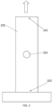
- a sample 200 (known as a coupon) was fixed at a first end 203 and a force applied to a second end 202 of the sample 200 in a direction along the length of the sample as shown by the arrow. The force was applied multiple times, as usual for fatigue testing.
- the sample 200 was 150mm long, 30mm wide and 3mm thick.
- a hole 201 of 10mm diameter was formed in the centre of the sample.
- Each sample used comprised continuous reinforcing elements in the form of alumina filaments dispersed in an aluminium matrix.
- Fig. 6 Mean electrical conductivity measurements for Sample 2 are shown in Fig. 6 .
- electrical conductivity is higher at all measurement sites than for the control, although not markedly higher in positions 1, 2 and 8.
- electrical conductivity is higher at positions 3, 4, 5, 6 and 7 than at other positions, and markedly higher in the case of positions 5, 6 and 7. Greater variation between measurements was observed at positions 3 and 6.
- Fig. 7 Mean electrical conductivity measurements for Sample 3 are shown in Fig. 7 .
- electrical conductivity is higher at all measurement sites than for the control, with the possible exception of measurement site 7.
- electrical conductivity is higher at positions 1, 2, 3, 4 and 6, and markedly higher in the case of position 1. Greater variation between measurements was observed at positions 2, 3 and 6.
- a raised value of electrical conductivity at a particular point compared to a control may be indicative of damage to a sample.
- raised values of electrical conductivity at a set of points may also be indicative of damage to a sample.
- the spatial pattern of said set of points comprising raised values of electrical conductivity may also be indicative of damage and/or indicative of a type of damage.
- the method merely comprises using the electrical conductivity measurement to determine estimated damage.
- Such an estimation is typically performed automatically using a suitably-programmed computing device, such as that described below with reference to Fig. 12 .
- measurement of electrical conductivity may facilitate the estimation of the remaining life of an aircraft structure. For example, a comparison may be made between the measured electrical conductivity and a pre-determined value indicative of a given percentage of a lifetime of an aircraft structure.
- the method is denoted generally by reference numeral 400, and comprises determining 401 an electrical conductivity or resistivity of the metal matrix composite, and estimating 402 the remaining operational life of aircraft structure from the electrical conductivity or resistivity.
- Fig. 11 is a schematic representation of how electrical conductivity may be related to the remaining operational life of the aircraft structure.
- the method merely comprises using the electrical conductivity measurement to determine an estimated remaining operational life. Such an estimation is typically performed automatically using a suitably-programmed computing device, such as that described below with reference to Fig. 12 .
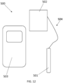
- the apparatus is denoted generally by reference numeral 500, and comprises a probe 501 in communication with a handset 502.
- the probe is an eddy current probe, such as those that are typically used to measure the electrical conductivity of a conductive, non-ferrous material.
- the handset 502 is configured to process signals provided by the probe 501. Together the handset 502 and probe 501 form a device 504 for determining electrical conductivity.
- One such device is the Sigmatest 2.069.
- the handset 502 is configured to transmit data to a handheld device 503, in this case a smartphone.
- the smartphone 503 is configured to estimate damage to an aircraft structure by comparing data received from device 504 with pre-determined data, as indicated above in relation to the methods of the present invention.
- the smartphone 503 is further configured to estimate the remaining operational life of an aircraft structure by comparing data received from device 504 with pre-determined data, as indicated above in relation to the methods of the present invention.
- the smartphone 503 is configured to communicate the estimated damage and/or the estimated remaining operational life to a user, for example, by visual means or by audio means.
- the method is denoted generally by reference numeral 600, and comprises determining 601 an electrical conductivity or resistivity of the metal matrix composite, comparing 602 the electrical conductivity or resistivity with one or more pre-determined values indicative of those from one or more as-manufactured samples and from that comparison determining 603 whether the sample is suitable for use.
- the pre-determined value may be a measured or calculated value that is stored electronically, for example, on a database. Such an estimation is typically performed automatically using a suitably-programmed computing device, such as that described above with reference to Fig. 12 .
- the MMC in the examples above is made using squeeze casting.
- the apparatus and methods of the present invention may be used to examine MMCs that are made using techniques other than squeeze casting.
Landscapes
- Engineering & Computer Science (AREA)
- General Physics & Mathematics (AREA)
- Physics & Mathematics (AREA)
- Aviation & Aerospace Engineering (AREA)
- Transportation (AREA)
- Manufacturing & Machinery (AREA)
- Chemical & Material Sciences (AREA)
- Health & Medical Sciences (AREA)
- General Health & Medical Sciences (AREA)
- Biochemistry (AREA)
- Immunology (AREA)
- Pathology (AREA)
- Analytical Chemistry (AREA)
- Life Sciences & Earth Sciences (AREA)
- Electrochemistry (AREA)
- Chemical Kinetics & Catalysis (AREA)
- Investigating Or Analyzing Materials By The Use Of Electric Means (AREA)
Abstract
Description
- The present disclosure relates to methods of testing metal matrix composite materials.
- The present invention concerns the testing of metal matrix composite materials. More particularly, but not exclusively, this invention concerns a method of examining the integrity of an aircraft structure comprising metal matrix composite. The invention also concerns a method of estimating damage in an aircraft structure comprising metal matrix composite, a method of estimating the remaining operational life of an aircraft structure comprising metal matrix composite, an apparatus for performing such methods, an apparatus configured to estimate damage in an aircraft structure comprising metal matrix composite and an apparatus configured to estimate the remaining operational life of an aircraft structure comprising metal matrix composite
- Aircraft structures comprising metal matrix composite (MMC) are well-known. The composite in the present context typically comprises a reinforcing material laid out as per a desired plan in a metallic matrix. The reinforcing material may be continuous, typically in the form of long filaments, or long or continuous fibres. The fibres or filaments are typically alumina, silicon carbide or carbon fibre. The metal matrix may, for example, comprise aluminium or an aluminium alloy.
- Structures comprising MMCs can be designed to endure better than many other types of metallic materials when subjected to cyclic, random or spectrum loading. However, it is desirable for aircraft manufacturers, repairers and servicing organisations to be able to determine the extent of damage upon a given aircraft structure. It is also desirable to be able to estimate the remaining lifetime of an aircraft structure. There are currently many ways of determining whether or not an MMC structure is becoming fatigued or otherwise damaged, such as Computer Tomography, Scanning Electron Microscopy, Transmission Electron Microscopy, Optical microscopy, X-ray diffraction and Energy Dispersive Spectrometry. Some such techniques are specialist in nature and require expensive equipment. Some of those techniques require samples to be taken from the aircraft structure and are therefore somewhat destructive in nature. One may also examine the stresses to which aircraft structures are subjected, for example by the use of a strain gauge. Strain gauges may only measure surface strain and may not determine whether an aircraft structure is damaged.
- The present invention seeks to mitigate the above-mentioned problems and/or provide an improved method of assessing the integrity of an aircraft structure comprising metal matrix composites.
- In accordance with a first aspect of the present invention, there is provided a method of assessing the integrity of an aircraft structure comprising metal matrix composite, the method comprising determining an electrical conductivity or resistivity of the metal matrix composite, and assessing the integrity of the aircraft structure from the determined electrical conductivity or resistivity.
- The applicant has unexpectedly determined that it is possible to examine the integrity of an aircraft structure comprising metal matrix composite simply by determining an electrical conductivity or resistivity of the metal matrix composite. Those skilled in the art will realise that conductivity is the reciprocal of resistivity, and determination of one of the conductivity or resistivity effectively determines the other of the conductivity and resistivity.
- For the avoidance of doubt, those skilled in the art will realise that reference herein to "conductivity" and "resistivity" is to "electrical conductivity" and "electrical resistivity" unless the context requires otherwise. Furthermore, if reference is made solely to "electrical conductivity" or "electrical resistivity" without reference to the other of electrical conductivity or electrical resistivity, then reference to the other is implied, unless the context requires otherwise. Similarly, if reference is made solely to "conductivity" or "resistivity" without reference to the other of conductivity or resistivity, then reference to the other is implied, unless the context requires otherwise.
- Assessing the integrity of the aircraft structure may, for example, comprise estimating damage to the aircraft structure and/or estimating remaining operational life of the aircraft structure.
- The method of the first aspect of the present invention is concerned with examining the integrity of an aircraft structure comprising metal matrix composite, and in particular examining the integrity of the metal matrix composite itself. Optionally, at least 40% of the volume of the aircraft structure under test is formed from metal matrix composite, optionally at least 50%, optionally at least 60%, optionally at least 70%, optionally at least 80%, optionally at least 90%, optionally at least 95%, optionally at least 97%, optionally at least 98%, optionally at least 99% and optionally at least 99.5% of the volume of the aircraft structure is formed from metal matrix composite. The aircraft structure may comprise coatings and the like formed on the metal matrix composite.
- The method may comprise determining an electrical conductivity or resistivity of the aircraft structure in situ. In this case, the aircraft structure remains as part of the aircraft while the determination of electrical conductivity or resistivity is made. The method may comprise determining an electrical conductivity or resistivity of an aircraft structure while the aircraft structure is removed from the aircraft.
- The aircraft structure of which the electrical conductivity or resistivity is determined may optionally be an aircraft structure that has been subjected to manufacturing, handling or service stress, for example, from repeated loading associated with flight.
- The method may comprise determining a first electrical conductivity or a first set of electrical conductivities at a first point in time. The method may comprise determining a second electrical conductivity or a second set of electrical conductivities at a second point in time, the aircraft structure optionally having been subjected to stress since the first point in time. The method may comprise comparing the first electrical conductivity with the second electrical conductivity, and optionally from said comparison, assessing the integrity of the aircraft structure. Assessing the integrity of the aircraft structure may comprise estimating damage to the aircraft structure and/or estimating remaining operational life of the aircraft structure. For the avoidance of doubt, "damage" in this sense is typically not limited to the type of damage associated with failure of the aircraft structure; "damage" in this sense includes microscopic damage, typically associated with exposure to the repeated application and release of stress, that is typically not catastrophic but may limit the operational lifetime of an aircraft structure. The method may comprise comparing the first set of electrical conductivities with the second set of electrical conductivities, and optionally from said comparison, assessing the integrity of the aircraft structure, for example, estimating damage to the aircraft structure and/or estimating the remaining operational life of the aircraft structure. The first set of electrical conductivities may comprise determining electrical conductivity at a plurality of spatially-separated positions on the aircraft structure, optionally on a first side of the aircraft structure. The second set of electrical conductivities may comprise determining electrical conductivity at said plurality of spatially-separated positions on the aircraft structure, said plurality of spatially-separated positions being the same plurality of spatially-separated positions as the first set of electrical conductivities, optionally on the first side of the aircraft structure. The method may therefore comprise determining the electrical conductivity of the aircraft structure in lots of positions on the aircraft structure at different points in time, and on the same side of the aircraft structure, and seeing how the electrical conductivity at all those points varies over time.
- The method may comprise determining a first set of electrical conductivities or resistivities, thereby determining electrical conductivity or resistivity at a plurality of spatially-separated positions on the aircraft structure. The method may comprise assessing the integrity of the aircraft structure, for example, estimating damage to the aircraft structure and/or estimating remaining life of the aircraft structure from the first set of electrical conductivities or resistivities. The method may comprise comparing the first set of electrical conductivities or resistivities to a set of electrical conductivities or resistivities indicative of an as-manufactured aircraft structure. In this context "as-manufactured" refers to an aircraft structure that has been manufactured to requirements, and has not been installed on an aircraft. The set of electrical conductivities or resistivities indicative of an as-manufactured aircraft structure may comprise measured and/or calculated electrical conductivity or resistivity values. Typically, the first set of electrical conductivities or resistivities are obtained from a first side of the aircraft structure, and may be compared with a set of electrical electrical conductivities or resistivities indicative of an as-manufactured aircraft structure, and taken from the first side of the as-manufactured aircraft structure.
- The method may comprise comparing the electrical conductivity or resistivity with a value indicative of an electrical conductivity or resistivity of an as-manufactured aircraft structure. The as-manufactured aircraft structure may be substantially the same as the aircraft structure for which the electrical conductivity or resistivity has been determined, save that the as-manufactured aircraft structure has not been subjected to post-manufacture stress, such as static loading stress and/or in-flight stress. The aircraft structure under test may or may not have been subjected to post-manufacture stress, such as in-flight stress. The value indicative of an electrical conductivity or resistivity of an as-manufactured aircraft structure may be a measured value or a calculated value, for example. The value indicative of an electrical conductivity or resistivity of an as-manufactured aircraft structure may have been stored electronically, for example, as part of a database.
- The method may comprise comparing the electrical conductivity or resistivity with a value indicative of an electrical conductivity or resistivity of an as-manufactured aircraft structure, and based on said comparison, assessing the integrity of the aircraft structure, for example, estimating the damage to the aircraft structure and/or estimating remaining operational life of the aircraft structure. Estimation of damage may, for example, comprise estimating whether or not there has been damage. Alternatively or additionally, estimate of damage may comprise estimating a quantum of damage. Estimating remaining operational life may, for example, comprise estimating whether or not the aircraft structure has any remaining operational life. Alternatively or additionally, estimating remaining operational life may, for example, comprise estimating a quantum of remaining operational life. Typically, the electrical conductivity of an aircraft structure that is damaged, for example, by being subjected to repeated stress, is greater than a corresponding aircraft structure that has not been subjected to stress. For example, if the electrical conductivity of the aircraft structure under test is greater than the as-manufactured aircraft structure, and optionally above a minimum threshold value, then this may be indicative that the aircraft structure under test is, to some extent, damaged. Those skilled in the art will realise that one may place a minimum threshold value on the conductivity measurement that would be deemed to be indicative of damage.
- The method may comprise comparing the electrical conductivity or resistivity with one or more pre-determined values indicative of those from stressed or damaged samples. The one or more pre-determined values indicative of those from stressed or damaged samples are optionally pre-determined values relating to the same side of a sample from which the measured electrical conductivity or resistivity was determined. The one or more pre-determined values indicative of those from stressed or damaged samples may be measured or calculated values. For example, the method may comprise comparing the electrical conductivity or resistivity of the aircraft structure under test with a data set associated with stressed or damaged samples, the data set comprising data associated with samples having been subjected to different amounts of stress and/or damage. In this way, one can assess the integrity of the aircraft structure, for example, estimate the stress and/or damage to which the sample under test has been subjected, and may optionally be used to estimate remaining operational life of the aircraft structure.
- The method may comprise determining a first set of electrical conductivities or resistivities, and comparing the first set of electrical conductivities or resistivities with a set of one or more pre-determined values indicative of those from stressed or damaged samples. The first set of electrical conductivities may comprise determining electrical conductivity at a plurality of spatially-separated positions on the aircraft structure. The method may comprise comparing each determination of the first set of electrical conductivities with one or more pre-determined values indicative of those from stressed or damaged samples. Therefore, we can use a spatially-distributed array of electrical conductivities to assess the integrity of the aircraft structure, for example, to estimate the stress and/or damage to which the sample under test has been subjected, and also to estimate the remaining operational life of the aircraft structure. Once again, the first set of electrical conductivities or resistivities are typically obtained from a first side of a sample, and they are compared with pre-determined values that are indicative of values obtained from the same (first) side of a stressed or damaged sample.
- Electrical conductivity or resistivity may be determined using an eddy current probe. Such probes may be suitable for determining electrical conductivity or resistivity in electrically-conductive non-ferrous materials.
- Metal matrix composites comprise reinforcing elements dispersed in a metal matrix. The reinforcing elements may be continuous, for example, in the form of filaments. The reinforcing elements may comprise one or more of alumina, silicon carbide or carbon fibre. The metal matrix may comprise one or more of aluminium, titanium or magnesium, for example. The metal matrix may be formed from a substantially pure metal, for example, aluminium (with other elements being present in an acceptable amount), or the matrix may be formed from an alloy. The method of the first aspect of the present invention may be used to examine metal matrix composite formed using any suitable method, such as solid state formation, liquid state formation, semi-solid state formation, vapour formation and in-situ fabrication.
- According to a second aspect of the present invention, there is also provided a method of estimating damage in an aircraft structure comprising metal matrix composite, the method comprising determining an electrical conductivity or resistivity of the metal matrix composite, and estimating damage to the aircraft structure from the electrical conductivity or resistivity.
- The applicant has found that it is possible to estimate damage to the aircraft structure from an electrical conductivity or resistivity measurement.
- According to a third aspect of the present invention, there is also provided a method of estimating the remaining operational life of an aircraft structure comprising metal matrix composite, the method comprising determining an electrical conductivity or resistivity of the metal matrix composite, and estimating the remaining operational life of the aircraft structure from the electrical conductivity or resistivity.
- The applicant has found that it is possible to estimate damage to the aircraft structure from an electrical conductivity or resistivity measurement.
- According to a fourth aspect of the present invention, there is also provided a method of determining the suitability of an aircraft structure comprising metal matrix composite, the method comprising determining an electrical conductivity or resistivity of the metal matrix composite, and determining whether or not the aircraft structure is suitable from the electrical conductivity or resistivity. The method may be a method of quality control of an aircraft structure.
- The methods of the second, third and fourth aspects of the present invention may comprise any of the features of the method of the first aspect of the present invention. For example, the method of the second and third aspect of the invention may comprise comparing the electrical conductivity or resistivity with one or more pre-determined values indicative of those from stressed or damaged samples. The one or more pre-determined values indicative of those from stressed or damaged samples may be measured or calculated values. For example, the method may comprise comparing the electrical conductivity or resistivity with a data set associated with stressed or damaged samples, the data set comprising data associated with samples having been subjected to different amounts of stress and/or damage. In this way, one can estimate the stress and/or damage to which the sample under test has been subjected, and may optionally be used to estimate remaining operational life of the aircraft structure. The method of the fourth aspect of the present invention may comprise comparing the electrical conductivity or resistivity with one or more pre-determined values indicative of those from as-manufactured samples. For example, if the electrical conductivity or resistivity measurement taken from the sample is comparable to the one or more predetermined values indicative of those from as-manufactured samples, then the test sample may be determined to be suitable for use.
- The methods of the first, second, third and fourth aspects of the present invention may be used on structures other than aircraft structures. For example, it may be possible to perform those methods on any metal matrix composite structure, not just an aircraft structure.
- According to a fifth aspect of the present invention, there is also provided an apparatus configured to perform a method in accordance with the first aspect of the present invention. The apparatus comprises a computing device and a device for determining electrical conductivity or resistivity, configured to transmit electrical conductivity or resistivity data to the computing device. The computing device may be a mobile computing device, for example, such as a mobile phone, tablet or laptop computer. The computing device may be configured to process data received from the device for determining electrical conductivity or resistivity in order to assess the integrity of the aircraft structure.
- According to a sixth aspect of the present invention, there is also provided an apparatus configured to estimate damage in an aircraft structure comprising metal matrix composite, the apparatus comprising a computing device and a device for determining electrical conductivity or resistivity, configured to transmit electrical conductivity or resistivity data to the computing device, the computing device being configured to estimate damage in the aircraft structure from electrical conductivity or resistivity data received from the device for determining electrical conductivity or resistivity. The apparatus of the sixth aspect of the present invention may be configured to perform the method of the second aspect of the present invention.
- According to a seventh aspect of the present invention, there is also provided an apparatus configured to estimate the remaining operational life of an aircraft structure comprising metal matrix composite, the apparatus comprising a computing device and a device for determining electrical conductivity or resistivity, configured to transmit electrical conductivity or resistivity data to the computing device, the computing device being configured to estimate the remaining operational life of the aircraft structure from electrical conductivity or resistivity data received from the device for determining electrical conductivity or resistivity. The apparatus of the seventh aspect of the present invention may be configured to perform the method of the third aspect of the present invention.
- It will of course be appreciated that features described in relation to one aspect of the present invention may be incorporated into other aspects of the present invention. For example, the method of the invention may incorporate any of the features described with reference to the apparatus of the invention and vice versa.
- Embodiments of the present invention will now be described by way of example only with reference to the accompanying schematic drawings of which:
-
Figure 1 shows a schematic representation of an example of an embodiment of a method according to the first aspect of the present invention; -
Figure 2 shows a schematic plan view of a sample of metal matrix composite being subjected to stress; -
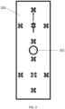
Figure 3 shows a schematic plan view of a sample of metal matrix composite, indicating the positions of the electrical conductivity measurement sites; -
Figure 4 shows the electrical conductivity measurements taken from a sample prior to loading cyclically towards the introduction of metal fatigue, the positions of the electrical conductivity measurement sites being indicated inFigure 3 ; -
Figure 5 shows the electrical conductivity measurements taken from a first sample subjected to stress by cyclic loading, the positions of the electrical conductivity measurement sites being indicated inFigure 3 ; -
Figure 6 shows the electrical conductivity measurements taken from a second sample subjected to stress by cyclic loading, the positions of the electrical conductivity measurement sites being indicated inFigure 3 ; -
Figure 7 shows the electrical conductivity measurements taken from a third sample subjected to stress by cyclic loading, the positions of the electrical conductivity measurement sites being indicated inFigure 3 ; -
Figure 8 shows a schematic representation of an example of an embodiment of a method of estimating damage according to the second aspect of the present invention; -
Figure 9 shows a schematic representation of an example of an embodiment of a method of estimating the remaining operational life of an aircraft structure according to the third aspect of the present invention; -
Figure 10 shows a schematic representation of how a measured electrical conductivity may be related to damage to an aircraft structure; -
Figure 11 shows a schematic representation of how a measured electrical conductivity may be related to remaining operational life of an aircraft structure; -
Figure 12 shows a schematic representation of an example of an embodiment of an apparatus configured to estimate damage in an aircraft structure and to estimate the remaining operational life of an aircraft structure according to the sixth and seventh aspects of the present invention; and -
Figure 13 shows a schematic representation of an example of an embodiment of a method of determining the suitability of an aircraft structure comprising metal matrix composite according to the fourth aspect of the present invention. - An example of a method of examining the integrity of an aircraft structure comprising metal matrix composite in accordance with the first aspect of the present invention will now be described with reference to
Figs. 1 ,2 and3 . Referring toFig. 1 , the method is denoted generally byreference numeral 100, and comprises determining 101 an electrical conductivity of the metal matrix composite. Thatdetermination 101 may then be used to assess 102 the integrity of the aircraft structure, for example, to estimate damage to the aircraft structure and/or remaining operational life of the aircraft structure. - In the present examples, the aircraft structures under examination were coupons, such as those conventionally used in constant amplitude fatigue testing. The samples were subjected to repeated stress in accordance with DIN EN 6072 (constant amplitude fatigue testing). Referring to
Fig. 2 , a sample 200 (known as a coupon) was fixed at afirst end 203 and a force applied to asecond end 202 of thesample 200 in a direction along the length of the sample as shown by the arrow. The force was applied multiple times, as usual for fatigue testing. Thesample 200 was 150mm long, 30mm wide and 3mm thick. Ahole 201 of 10mm diameter was formed in the centre of the sample. Each sample used comprised continuous reinforcing elements in the form of alumina filaments dispersed in an aluminium matrix. Each sample was prepared by squeeze casting. Those skilled in the art will realise that other metals and/or reinforcing elements may be used. Three samples were studied, along with an as-manufactured control sample that had not been subjected to fatigue testing, and details of those samples are shown below in Table 1. In each case, a force was applied to the sample a number of times, and released to a tenth of its value (corresponding to an R-value of 0.1, as is usually the case for this type of testing). It should be noted that none of Samples 1-3 had failed i.e. there was no gross failure of the structure.Table 1 - samples subjected to electrical conductivity measurements Sample No. Force applied to sample (kN) No. of times force applied to sample 1 26.85 1,146,159 2 28.07 1,729,542 3 11.09 >107 Control 0 0 - Electrical conductivity measurements were performed on Samples 1-3 and the Control using a Sigmatest 2.069 electrical conductivity meter (Foerster Instruments Incorporated, Pittsburgh, USA). Ten measurements were taken at each of ten positions on the same side of a sample using a measurement frequency of 960kHz, the positions being shown as reference numerals 1-10 on
sample 200 inFig. 3 , and the mean value calculated for each position.Fig. 4 shows the electrical conductivity measurements taken from the control sample (an as-manufactured sample that had not been subjected to fatigue testing). The electrical conductivity at each measurement position was approximately constant at about 1-2MS/m. Measurements were also performed at 60kHz, but those measurements were found to be less satisfactory than at 960kHz, likely due to better penetration of the sample by the 960kHz measurement signal. - Mean electrical conductivity measurements for
Sample 1 are shown inFig. 5 . Electrical conductivity is higher at all measurement sites than for the control. Furthermore, electrical conductivity is higher atpositions positions - Mean electrical conductivity measurements for
Sample 2 are shown inFig. 6 . As forSample 1, electrical conductivity is higher at all measurement sites than for the control, although not markedly higher inpositions positions positions positions - Mean electrical conductivity measurements for
Sample 3 are shown inFig. 7 . As forSamples measurement site 7. Furthermore, electrical conductivity is higher atpositions position 1. Greater variation between measurements was observed atpositions - Without wishing to be bound by theory, it is anticipated that damage to the sample is associated with a higher electrical conductivity, and the determination of a raised electrical conductivity compared to a pre-determined control conductivity is indicative of microscopic damage to the sample. As mentioned above, Samples 1-3 have not failed i.e. they have not undergone a gross structural failure. Once again, without wishing to be bound by theory, it is anticipated that microscopic damage to the sample may take several forms, such as void formation in the matrix, crack formation in the matrix, breakage of the reinforcing members and separation of the reinforcing members from the matrix.
- A raised value of electrical conductivity at a particular point compared to a control may be indicative of damage to a sample. Furthermore, raised values of electrical conductivity at a set of points may also be indicative of damage to a sample. Furthermore, the spatial pattern of said set of points comprising raised values of electrical conductivity may also be indicative of damage and/or indicative of a type of damage. In this connection, a method of estimating damage in an aircraft structure will now be described with reference to
Figs. 8 and10 . The method is denoted generally byreference numeral 300, and comprises determining 301 an electrical conductivity or resistivity of the metal matrix composite, and estimating 302 damage to the aircraft structure from the electrical conductivity or resistivity.Fig. 10 is a schematic representation of how electrical conductivity may be related to damage to the aircraft structure. In order to estimate damage to the aircraft structure, the method merely comprises using the electrical conductivity measurement to determine estimated damage. Such an estimation is typically performed automatically using a suitably-programmed computing device, such as that described below with reference toFig. 12 . - Once again, without wishing to be bound by theory, it is anticipated that measurement of electrical conductivity may facilitate the estimation of the remaining life of an aircraft structure. For example, a comparison may be made between the measured electrical conductivity and a pre-determined value indicative of a given percentage of a lifetime of an aircraft structure.
- While it is anticipated that a single value of electrical conductivity at a particular point may be used to estimate the remaining life of an aircraft structure, it is also anticipated that a one or more values of electrical conductivity at each of a set of points may also be indicative of damage to a sample. Furthermore, the spatial pattern of said set of points may also be used to determine the remaining life of an aircraft structure.
- In this connection, a method of estimating the remaining operational life of an aircraft structure will now be described with reference to
Figs. 9 and11 . The method is denoted generally byreference numeral 400, and comprises determining 401 an electrical conductivity or resistivity of the metal matrix composite, and estimating 402 the remaining operational life of aircraft structure from the electrical conductivity or resistivity.Fig. 11 is a schematic representation of how electrical conductivity may be related to the remaining operational life of the aircraft structure. In order to estimate the remaining operational life of the aircraft structure, the method merely comprises using the electrical conductivity measurement to determine an estimated remaining operational life. Such an estimation is typically performed automatically using a suitably-programmed computing device, such as that described below with reference toFig. 12 . - An example of an apparatus configured to estimate damage to an aircraft structure and to determine the remaining operational life of an aircraft structure will now be described with reference to
Fig. 12 . The apparatus is denoted generally byreference numeral 500, and comprises aprobe 501 in communication with ahandset 502. The probe is an eddy current probe, such as those that are typically used to measure the electrical conductivity of a conductive, non-ferrous material. Thehandset 502 is configured to process signals provided by theprobe 501. Together thehandset 502 and probe 501 form adevice 504 for determining electrical conductivity. One such device is the Sigmatest 2.069. Thehandset 502 is configured to transmit data to ahandheld device 503, in this case a smartphone. Thesmartphone 503 is configured to estimate damage to an aircraft structure by comparing data received fromdevice 504 with pre-determined data, as indicated above in relation to the methods of the present invention. Thesmartphone 503 is further configured to estimate the remaining operational life of an aircraft structure by comparing data received fromdevice 504 with pre-determined data, as indicated above in relation to the methods of the present invention. Thesmartphone 503 is configured to communicate the estimated damage and/or the estimated remaining operational life to a user, for example, by visual means or by audio means. - A method of determining the suitability of an aircraft structure comprising metal matrix composite will now be described with reference to
Figure 13 . The method is denoted generally byreference numeral 600, and comprises determining 601 an electrical conductivity or resistivity of the metal matrix composite, comparing 602 the electrical conductivity or resistivity with one or more pre-determined values indicative of those from one or more as-manufactured samples and from that comparison determining 603 whether the sample is suitable for use. The pre-determined value may be a measured or calculated value that is stored electronically, for example, on a database. Such an estimation is typically performed automatically using a suitably-programmed computing device, such as that described above with reference toFig. 12 . - Whilst the present invention has been described and illustrated with reference to particular embodiments, it will be appreciated by those of ordinary skill in the art that the invention lends itself to many different variations not specifically illustrated herein. By way of example only, certain possible variations will now be described.
- The examples above describe the measurement of electrical conductivity. Those skilled in the art will realise that electrical resistivity is the reciprocal of electrical conductivity, and therefore the methods and apparatus of the present invention may be used to determine electrical resistivity, instead of conductivity.
- The examples above describe the use of a probe that uses the eddy current method to determine electrical conductivity. Those skilled in the art will realise that other types of probe or measurement techniques may be used.
- The examples above describe the measurement of electrical conductivity in a metal matrix composite comprising an aluminium metal matrix. Those skilled in the art will realise that the methods and apparatus of the present invention may be used to examine MMCs comprising metals other than aluminium, such as aluminium alloys, titanium and magnesium.
- Those skilled in the art will realise that the apparatus and methods of the present invention may be used to examine MMCs comprising reinforcing elements made from materials other than alumina.
- The MMC in the examples above is made using squeeze casting. Those skilled in the art will realise that the apparatus and methods of the present invention may be used to examine MMCs that are made using techniques other than squeeze casting.
- Where in the foregoing description, integers or elements are mentioned which have known, obvious or foreseeable equivalents, then such equivalents are herein incorporated as if individually set forth. Reference should be made to the claims for determining the true scope of the present invention, which should be construed so as to encompass any such equivalents. It will also be appreciated by the reader that integers or features of the invention that are described as preferable, advantageous, convenient or the like are optional and do not limit the scope of the independent claims. Moreover, it is to be understood that such optional integers or features, whilst of possible benefit in some embodiments of the invention, may not be desirable, and may therefore be absent, in other embodiments.
Claims (15)
- A method of examining the integrity of an aircraft structure comprising metal matrix composite, the method comprising determining an electrical conductivity or resistivity of the metal matrix composite, and assessing the integrity of the aircraft structure from the determined electrical conductivity or resistivity.
- The method of claim 1 comprising determining a first electrical conductivity or a first set of electrical conductivities at a first point in time and determining a second electrical conductivity at a second point in time, the aircraft structure having been subjected to stress since the first point in time, the method comprising comparing the first electrical conductivity with the second electrical conductivity, and from said comparison, assessing the integrity of the aircraft structure.
- The method of claim 1 or claim 2, comprising determining a first set of electrical conductivities or resistivities, thereby determining electrical conductivity or resistivity at a plurality of spatially-separated positions on the aircraft structure, and assessing the integrity of the aircraft structure from the first set of electrical conductivities or resistivities, the method optionally comprising comparing the first set of electrical conductivities or resistivities to a set of electrical conductivities or resistivities indicative of an as-manufactured aircraft structure.
- The method of any preceding claim comprising comparing the electrical conductivity or resistivity with a value indicative of an electrical conductivity or resistivity of an as-manufactured aircraft structure, and based on said comparison, assessing the integrity of the aircraft structure.
- The method of any preceding claim comprising comparing the electrical conductivity or resistivity with one or more pre-determined values indicative of those from stressed or damaged samples, and from said comparison assessing the integrity of the aircraft structure.
- The method of claim 5, comprising determining a first set of electrical conductivities or resistivities, and comparing the first set of electrical conductivities or resistivities with a set of one or more pre-determined values indicative of those from stressed or damaged samples, the first set of electrical conductivities or resistivities having been determined at a plurality of spatially-separated positions on the aircraft structure, the method comprising comparing each determination of the first set of electrical conductivities or resistivities with one or more pre-determined values indicative of those from stressed or damaged samples.
- The method of any preceding claim, wherein the metal matrix composite comprises reinforcing elements dispersed in a metal matrix, and wherein the reinforcing elements are continuous.
- The method according to claim 6 or claim 7, wherein the reinforcing elements comprise one or more of alumina, silicon carbide or carbon fibre, and wherein the metal matrix comprises one or more of aluminium, titanium or magnesium.
- The method of any preceding claim, wherein assessing the integrity of the aircraft structure comprises estimating damage to the aircraft structure and/or estimating the remaining operational life of the aircraft structure.
- A method of estimating damage in an aircraft structure comprising metal matrix composite, the method comprising determining an electrical conductivity or resistivity of the metal matrix composite, and estimating damage to the aircraft structure from the electrical conductivity or resistivity.
- A method of estimating the remaining operational life of an aircraft structure comprising metal matrix composite, the method comprising determining an electrical conductivity or resistivity of the metal matrix composite, and estimating the remaining operational life of the aircraft structure from the electrical conductivity or resistivity.
- A method of determining the suitability of an aircraft structure comprising metal matrix composite, the method comprising determining an electrical conductivity or resistivity of the metal matrix composite, and determining whether or not the aircraft structure is suitable from the electrical conductivity or resistivity.
- An apparatus configured to perform a method according to any of claims 1 to 9, the apparatus comprising a computing device and a device for determining electrical conductivity or resistivity, configured to transmit electrical conductivity or resistivity data to the computing device, the computing device being configured to assess the integrity of the aircraft structure from the electrical conductivity or resistivity.
- An apparatus configured to estimate damage in an aircraft structure comprising metal matrix composite, the apparatus comprising a computing device and a device for determining electrical conductivity or resistivity, configured to transmit electrical conductivity or resistivity data to the computing device, the computing device being configured to estimate damage in the aircraft structure from electrical conductivity or resistivity data received from the device for determining electrical conductivity or resistivity.
- An apparatus configured to estimate the remaining operational life of an aircraft structure comprising metal matrix composite, the apparatus comprising a computing device and a device for determining electrical conductivity or resistivity, configured to transmit electrical conductivity or resistivity data to the computing device, the computing device being configured to estimate the remaining operational life of the aircraft structure from electrical conductivity or resistivity data received from the device for determining electrical conductivity or resistivity.
Applications Claiming Priority (1)
| Application Number | Priority Date | Filing Date | Title |
|---|---|---|---|
| GB2114348.2A GB2611548A (en) | 2021-10-07 | 2021-10-07 | Non-destructive testing method |
Publications (1)
| Publication Number | Publication Date |
|---|---|
| EP4163627A1 true EP4163627A1 (en) | 2023-04-12 |
Family
ID=78595054
Family Applications (1)
| Application Number | Title | Priority Date | Filing Date |
|---|---|---|---|
| EP22199663.0A Pending EP4163627A1 (en) | 2021-10-07 | 2022-10-04 | Non-destructive testing methods for examining aircraft structures |
Country Status (3)
| Country | Link |
|---|---|
| US (1) | US12410999B2 (en) |
| EP (1) | EP4163627A1 (en) |
| GB (1) | GB2611548A (en) |
Citations (8)
| Publication number | Priority date | Publication date | Assignee | Title |
|---|---|---|---|---|
| US20040066188A1 (en) * | 1999-09-07 | 2004-04-08 | Jentek Sensors, Inc. | Material condition assessment with spatially periodic field sensors |
| GB2405934A (en) * | 2003-09-09 | 2005-03-16 | Qinetiq Ltd | Resistance strain/moisture gauge |
| EP2392905A1 (en) * | 2010-06-01 | 2011-12-07 | The Boeing Company | Structural health management device and associated system and method |
| CN102878920A (en) * | 2012-07-23 | 2013-01-16 | 中国电子科技集团公司第八研究所 | Airplane strength and strain detection method and airplane strength and strain detecting system adopting same |
| US20150274312A1 (en) * | 2014-03-28 | 2015-10-01 | Bell Helicopter Textron Inc. | Aircraft Prognostics Health System |
| EP3348984A1 (en) * | 2017-01-16 | 2018-07-18 | The Boeing Company | Structural health monitoring system |
| WO2020165670A1 (en) * | 2019-02-11 | 2020-08-20 | Mesomat Inc. | Sensing fibers for structural strain monitoring |
| CN112285162A (en) * | 2020-10-18 | 2021-01-29 | 西安交通大学 | A system and method for detecting self-sensing properties of metal matrix composites based on continuous carbon core piezoelectric fibers |
Family Cites Families (4)
| Publication number | Priority date | Publication date | Assignee | Title |
|---|---|---|---|---|
| US8451013B1 (en) | 2009-04-30 | 2013-05-28 | Kuang-Ting Hsiao | Insulated fiber sensor apparatus and method |
| WO2015077102A1 (en) * | 2013-11-25 | 2015-05-28 | Oil States Industries, Inc. | Method and system for health monitoring of composite elastomeric flexible elements |
| US11275036B2 (en) | 2016-12-09 | 2022-03-15 | Nanyang Technological University | Non-destructive testing methods and apparatus |
| US11002701B2 (en) | 2018-11-07 | 2021-05-11 | Cameron International Corporation | Electrically smart multi-layered coating for condition-base monitoring |
-
2021
- 2021-10-07 GB GB2114348.2A patent/GB2611548A/en active Pending
-
2022
- 2022-10-04 EP EP22199663.0A patent/EP4163627A1/en active Pending
- 2022-10-06 US US17/961,157 patent/US12410999B2/en active Active
Patent Citations (8)
| Publication number | Priority date | Publication date | Assignee | Title |
|---|---|---|---|---|
| US20040066188A1 (en) * | 1999-09-07 | 2004-04-08 | Jentek Sensors, Inc. | Material condition assessment with spatially periodic field sensors |
| GB2405934A (en) * | 2003-09-09 | 2005-03-16 | Qinetiq Ltd | Resistance strain/moisture gauge |
| EP2392905A1 (en) * | 2010-06-01 | 2011-12-07 | The Boeing Company | Structural health management device and associated system and method |
| CN102878920A (en) * | 2012-07-23 | 2013-01-16 | 中国电子科技集团公司第八研究所 | Airplane strength and strain detection method and airplane strength and strain detecting system adopting same |
| US20150274312A1 (en) * | 2014-03-28 | 2015-10-01 | Bell Helicopter Textron Inc. | Aircraft Prognostics Health System |
| EP3348984A1 (en) * | 2017-01-16 | 2018-07-18 | The Boeing Company | Structural health monitoring system |
| WO2020165670A1 (en) * | 2019-02-11 | 2020-08-20 | Mesomat Inc. | Sensing fibers for structural strain monitoring |
| CN112285162A (en) * | 2020-10-18 | 2021-01-29 | 西安交通大学 | A system and method for detecting self-sensing properties of metal matrix composites based on continuous carbon core piezoelectric fibers |
Also Published As
| Publication number | Publication date |
|---|---|
| GB2611548A (en) | 2023-04-12 |
| US20230114974A1 (en) | 2023-04-13 |
| GB202114348D0 (en) | 2021-11-24 |
| US12410999B2 (en) | 2025-09-09 |
Similar Documents
| Publication | Publication Date | Title |
|---|---|---|
| Sam-Daliri et al. | Impedance analysis for condition monitoring of single lap CNT-epoxy adhesive joint | |
| US8443678B2 (en) | Apparatus for evaluation of coated parts | |
| Maillet et al. | Waveform-based selection of acoustic emission events generated by damage in composite materials | |
| US7719266B1 (en) | Non-destructive testing apparatus for the detection of corrosion | |
| Gadomski et al. | Experimental investigation of fatigue destruction of CFRP using the electrical resistance change method | |
| Zhang et al. | A method for determining elastic properties of micron-sized polymer particles by using flat punch test | |
| Zheng et al. | A novel evaluation strategy for fatigue reliability of flexible nanoscale films | |
| De Pannemaecker et al. | In situ fretting fatigue crack propagation analysis using synchrotron X-ray radiography | |
| Chi | Specimen size effects on the compressive strength and Weibull modulus of nuclear graphite of different coke particle size: IG-110 and NBG-18 | |
| Infante-Garcia et al. | Numerical analysis of the influence of micro-voids on fretting fatigue crack initiation lifetime | |
| KR101176958B1 (en) | Three point bending test machine | |
| EP4163627A1 (en) | Non-destructive testing methods for examining aircraft structures | |
| Zhang et al. | Phase identification of dual-phase (DP980) steels by electron backscatter diffraction and nanoindentation techniques | |
| Xue et al. | Monitoring the damage evolution of flexural fatigue in unidirectional carbon/carbon composites by electrical resistance change method | |
| Sauer et al. | Test setup for analyzing the electrical resistance during fatigue loading for metastable austenite AISI 304L and its diffusion-brazed joints | |
| CN113627012B (en) | A Method for Predicting the Fracture Strength of Carbon Fiber/Metal Layered Structures after Surface Scratching | |
| Sam-Daliri et al. | Condition monitoring of crack extension in the reinforced adhesive joint by carbon nanotubes | |
| Luo et al. | Eccentric compression behaviour of corroded H-section column: Testing, simulation and theoretical analysis | |
| JP5583489B2 (en) | Method and apparatus for evaluating damage of metal materials | |
| Kwon et al. | Strain sensing characteristics using piezoresistivity of semi-conductive silicon carbide fibers | |
| Bahri et al. | Estimation of the elastic modulus of the alumina coated AA1050 aluminum: Modeling and experiments | |
| Yang | Stress and strain concentration factors for tension bars of circular cross-section with semicircular groove | |
| Goswami et al. | Residual stress and localized lattice rotation under fatigue loading | |
| Sarvghad et al. | Scanning Kelvin Probe Force Microscopy as a means for comparative quantification of cold-rolling and visualizing the surface susceptibility to galvanic cells; compared to neutron diffraction and EBSD | |
| JP4672616B2 (en) | Evaluation method of stress corrosion crack growth rate |
Legal Events
| Date | Code | Title | Description |
|---|---|---|---|
| PUAI | Public reference made under article 153(3) epc to a published international application that has entered the european phase |
Free format text: ORIGINAL CODE: 0009012 |
|
| STAA | Information on the status of an ep patent application or granted ep patent |
Free format text: STATUS: THE APPLICATION HAS BEEN PUBLISHED |
|
| AK | Designated contracting states |
Kind code of ref document: A1 Designated state(s): AL AT BE BG CH CY CZ DE DK EE ES FI FR GB GR HR HU IE IS IT LI LT LU LV MC ME MK MT NL NO PL PT RO RS SE SI SK SM TR |
|
| STAA | Information on the status of an ep patent application or granted ep patent |
Free format text: STATUS: REQUEST FOR EXAMINATION WAS MADE |
|
| 17P | Request for examination filed |
Effective date: 20231003 |
|
| RBV | Designated contracting states (corrected) |
Designated state(s): AL AT BE BG CH CY CZ DE DK EE ES FI FR GB GR HR HU IE IS IT LI LT LU LV MC ME MK MT NL NO PL PT RO RS SE SI SK SM TR |
|
| STAA | Information on the status of an ep patent application or granted ep patent |
Free format text: STATUS: EXAMINATION IS IN PROGRESS |
|
| 17Q | First examination report despatched |
Effective date: 20250522 |