EP4163503A1 - Time delay valve and flow rate controller - Google Patents
Time delay valve and flow rate controller Download PDFInfo
- Publication number
- EP4163503A1 EP4163503A1 EP20938817.2A EP20938817A EP4163503A1 EP 4163503 A1 EP4163503 A1 EP 4163503A1 EP 20938817 A EP20938817 A EP 20938817A EP 4163503 A1 EP4163503 A1 EP 4163503A1
- Authority
- EP
- European Patent Office
- Prior art keywords
- fluid
- supply
- pilot
- valve
- flow path
- Prior art date
- Legal status (The legal status is an assumption and is not a legal conclusion. Google has not performed a legal analysis and makes no representation as to the accuracy of the status listed.)
- Granted
Links
Images







Classifications
-
- F—MECHANICAL ENGINEERING; LIGHTING; HEATING; WEAPONS; BLASTING
- F16—ENGINEERING ELEMENTS AND UNITS; GENERAL MEASURES FOR PRODUCING AND MAINTAINING EFFECTIVE FUNCTIONING OF MACHINES OR INSTALLATIONS; THERMAL INSULATION IN GENERAL
- F16K—VALVES; TAPS; COCKS; ACTUATING-FLOATS; DEVICES FOR VENTING OR AERATING
- F16K31/00—Actuating devices; Operating means; Releasing devices
- F16K31/12—Actuating devices; Operating means; Releasing devices actuated by fluid
- F16K31/36—Actuating devices; Operating means; Releasing devices actuated by fluid in which fluid from the circuit is constantly supplied to the fluid motor
- F16K31/363—Actuating devices; Operating means; Releasing devices actuated by fluid in which fluid from the circuit is constantly supplied to the fluid motor the fluid acting on a piston
-
- F—MECHANICAL ENGINEERING; LIGHTING; HEATING; WEAPONS; BLASTING
- F15—FLUID-PRESSURE ACTUATORS; HYDRAULICS OR PNEUMATICS IN GENERAL
- F15B—SYSTEMS ACTING BY MEANS OF FLUIDS IN GENERAL; FLUID-PRESSURE ACTUATORS, e.g. SERVOMOTORS; DETAILS OF FLUID-PRESSURE SYSTEMS, NOT OTHERWISE PROVIDED FOR
- F15B21/00—Common features of fluid actuator systems; Fluid-pressure actuator systems or details thereof, not covered by any other group of this subclass
- F15B21/10—Delay devices or arrangements
-
- F—MECHANICAL ENGINEERING; LIGHTING; HEATING; WEAPONS; BLASTING
- F15—FLUID-PRESSURE ACTUATORS; HYDRAULICS OR PNEUMATICS IN GENERAL
- F15B—SYSTEMS ACTING BY MEANS OF FLUIDS IN GENERAL; FLUID-PRESSURE ACTUATORS, e.g. SERVOMOTORS; DETAILS OF FLUID-PRESSURE SYSTEMS, NOT OTHERWISE PROVIDED FOR
- F15B11/00—Servomotor systems without provision for follow-up action; Circuits therefor
- F15B11/02—Systems essentially incorporating special features for controlling the speed or actuating force of an output member
- F15B11/04—Systems essentially incorporating special features for controlling the speed or actuating force of an output member for controlling the speed
- F15B11/0413—Systems essentially incorporating special features for controlling the speed or actuating force of an output member for controlling the speed in one direction only, with no control in the reverse direction, e.g. check valve in parallel with a throttle valve
-
- F—MECHANICAL ENGINEERING; LIGHTING; HEATING; WEAPONS; BLASTING
- F15—FLUID-PRESSURE ACTUATORS; HYDRAULICS OR PNEUMATICS IN GENERAL
- F15B—SYSTEMS ACTING BY MEANS OF FLUIDS IN GENERAL; FLUID-PRESSURE ACTUATORS, e.g. SERVOMOTORS; DETAILS OF FLUID-PRESSURE SYSTEMS, NOT OTHERWISE PROVIDED FOR
- F15B11/00—Servomotor systems without provision for follow-up action; Circuits therefor
- F15B11/02—Systems essentially incorporating special features for controlling the speed or actuating force of an output member
- F15B11/04—Systems essentially incorporating special features for controlling the speed or actuating force of an output member for controlling the speed
- F15B11/044—Systems essentially incorporating special features for controlling the speed or actuating force of an output member for controlling the speed by means in the return line, i.e. "meter out"
-
- F—MECHANICAL ENGINEERING; LIGHTING; HEATING; WEAPONS; BLASTING
- F15—FLUID-PRESSURE ACTUATORS; HYDRAULICS OR PNEUMATICS IN GENERAL
- F15B—SYSTEMS ACTING BY MEANS OF FLUIDS IN GENERAL; FLUID-PRESSURE ACTUATORS, e.g. SERVOMOTORS; DETAILS OF FLUID-PRESSURE SYSTEMS, NOT OTHERWISE PROVIDED FOR
- F15B11/00—Servomotor systems without provision for follow-up action; Circuits therefor
- F15B11/06—Servomotor systems without provision for follow-up action; Circuits therefor involving features specific to the use of a compressible medium, e.g. air, steam
-
- F—MECHANICAL ENGINEERING; LIGHTING; HEATING; WEAPONS; BLASTING
- F15—FLUID-PRESSURE ACTUATORS; HYDRAULICS OR PNEUMATICS IN GENERAL
- F15B—SYSTEMS ACTING BY MEANS OF FLUIDS IN GENERAL; FLUID-PRESSURE ACTUATORS, e.g. SERVOMOTORS; DETAILS OF FLUID-PRESSURE SYSTEMS, NOT OTHERWISE PROVIDED FOR
- F15B13/00—Details of servomotor systems ; Valves for servomotor systems
- F15B13/02—Fluid distribution or supply devices characterised by their adaptation to the control of servomotors
- F15B13/04—Fluid distribution or supply devices characterised by their adaptation to the control of servomotors for use with a single servomotor
- F15B13/042—Fluid distribution or supply devices characterised by their adaptation to the control of servomotors for use with a single servomotor operated by fluid pressure
-
- F—MECHANICAL ENGINEERING; LIGHTING; HEATING; WEAPONS; BLASTING
- F15—FLUID-PRESSURE ACTUATORS; HYDRAULICS OR PNEUMATICS IN GENERAL
- F15B—SYSTEMS ACTING BY MEANS OF FLUIDS IN GENERAL; FLUID-PRESSURE ACTUATORS, e.g. SERVOMOTORS; DETAILS OF FLUID-PRESSURE SYSTEMS, NOT OTHERWISE PROVIDED FOR
- F15B15/00—Fluid-actuated devices for displacing a member from one position to another; Gearing associated therewith
- F15B15/08—Characterised by the construction of the motor unit
- F15B15/14—Characterised by the construction of the motor unit of the straight-cylinder type
- F15B15/1423—Component parts; Constructional details
- F15B15/1447—Pistons; Piston to piston rod assemblies
- F15B15/1452—Piston sealings
-
- F—MECHANICAL ENGINEERING; LIGHTING; HEATING; WEAPONS; BLASTING
- F15—FLUID-PRESSURE ACTUATORS; HYDRAULICS OR PNEUMATICS IN GENERAL
- F15B—SYSTEMS ACTING BY MEANS OF FLUIDS IN GENERAL; FLUID-PRESSURE ACTUATORS, e.g. SERVOMOTORS; DETAILS OF FLUID-PRESSURE SYSTEMS, NOT OTHERWISE PROVIDED FOR
- F15B15/00—Fluid-actuated devices for displacing a member from one position to another; Gearing associated therewith
- F15B15/20—Other details, e.g. assembly with regulating devices
- F15B15/28—Means for indicating the position, e.g. end of stroke
-
- G—PHYSICS
- G05—CONTROLLING; REGULATING
- G05D—SYSTEMS FOR CONTROLLING OR REGULATING NON-ELECTRIC VARIABLES
- G05D7/00—Control of flow
- G05D7/01—Control of flow without auxiliary power
- G05D7/0126—Control of flow without auxiliary power the sensing element being a piston or plunger associated with one or more springs
- G05D7/0133—Control of flow without auxiliary power the sensing element being a piston or plunger associated with one or more springs within the flow-path
- G05D7/014—Control of flow without auxiliary power the sensing element being a piston or plunger associated with one or more springs within the flow-path using sliding elements
-
- F—MECHANICAL ENGINEERING; LIGHTING; HEATING; WEAPONS; BLASTING
- F15—FLUID-PRESSURE ACTUATORS; HYDRAULICS OR PNEUMATICS IN GENERAL
- F15B—SYSTEMS ACTING BY MEANS OF FLUIDS IN GENERAL; FLUID-PRESSURE ACTUATORS, e.g. SERVOMOTORS; DETAILS OF FLUID-PRESSURE SYSTEMS, NOT OTHERWISE PROVIDED FOR
- F15B13/00—Details of servomotor systems ; Valves for servomotor systems
- F15B13/02—Fluid distribution or supply devices characterised by their adaptation to the control of servomotors
- F15B13/04—Fluid distribution or supply devices characterised by their adaptation to the control of servomotors for use with a single servomotor
- F15B13/0401—Valve members; Fluid interconnections therefor
- F15B13/0402—Valve members; Fluid interconnections therefor for linearly sliding valves, e.g. spool valves
-
- F—MECHANICAL ENGINEERING; LIGHTING; HEATING; WEAPONS; BLASTING
- F15—FLUID-PRESSURE ACTUATORS; HYDRAULICS OR PNEUMATICS IN GENERAL
- F15B—SYSTEMS ACTING BY MEANS OF FLUIDS IN GENERAL; FLUID-PRESSURE ACTUATORS, e.g. SERVOMOTORS; DETAILS OF FLUID-PRESSURE SYSTEMS, NOT OTHERWISE PROVIDED FOR
- F15B2211/00—Circuits for servomotor systems
- F15B2211/40—Flow control
- F15B2211/405—Flow control characterised by the type of flow control means or valve
- F15B2211/40507—Flow control characterised by the type of flow control means or valve with constant throttles or orifices
-
- F—MECHANICAL ENGINEERING; LIGHTING; HEATING; WEAPONS; BLASTING
- F15—FLUID-PRESSURE ACTUATORS; HYDRAULICS OR PNEUMATICS IN GENERAL
- F15B—SYSTEMS ACTING BY MEANS OF FLUIDS IN GENERAL; FLUID-PRESSURE ACTUATORS, e.g. SERVOMOTORS; DETAILS OF FLUID-PRESSURE SYSTEMS, NOT OTHERWISE PROVIDED FOR
- F15B2211/00—Circuits for servomotor systems
- F15B2211/40—Flow control
- F15B2211/405—Flow control characterised by the type of flow control means or valve
- F15B2211/40515—Flow control characterised by the type of flow control means or valve with variable throttles or orifices
-
- F—MECHANICAL ENGINEERING; LIGHTING; HEATING; WEAPONS; BLASTING
- F15—FLUID-PRESSURE ACTUATORS; HYDRAULICS OR PNEUMATICS IN GENERAL
- F15B—SYSTEMS ACTING BY MEANS OF FLUIDS IN GENERAL; FLUID-PRESSURE ACTUATORS, e.g. SERVOMOTORS; DETAILS OF FLUID-PRESSURE SYSTEMS, NOT OTHERWISE PROVIDED FOR
- F15B2211/00—Circuits for servomotor systems
- F15B2211/40—Flow control
- F15B2211/405—Flow control characterised by the type of flow control means or valve
- F15B2211/40576—Assemblies of multiple valves
-
- F—MECHANICAL ENGINEERING; LIGHTING; HEATING; WEAPONS; BLASTING
- F15—FLUID-PRESSURE ACTUATORS; HYDRAULICS OR PNEUMATICS IN GENERAL
- F15B—SYSTEMS ACTING BY MEANS OF FLUIDS IN GENERAL; FLUID-PRESSURE ACTUATORS, e.g. SERVOMOTORS; DETAILS OF FLUID-PRESSURE SYSTEMS, NOT OTHERWISE PROVIDED FOR
- F15B2211/00—Circuits for servomotor systems
- F15B2211/40—Flow control
- F15B2211/405—Flow control characterised by the type of flow control means or valve
- F15B2211/40576—Assemblies of multiple valves
- F15B2211/40584—Assemblies of multiple valves the flow control means arranged in parallel with a check valve
-
- F—MECHANICAL ENGINEERING; LIGHTING; HEATING; WEAPONS; BLASTING
- F15—FLUID-PRESSURE ACTUATORS; HYDRAULICS OR PNEUMATICS IN GENERAL
- F15B—SYSTEMS ACTING BY MEANS OF FLUIDS IN GENERAL; FLUID-PRESSURE ACTUATORS, e.g. SERVOMOTORS; DETAILS OF FLUID-PRESSURE SYSTEMS, NOT OTHERWISE PROVIDED FOR
- F15B2211/00—Circuits for servomotor systems
- F15B2211/40—Flow control
- F15B2211/405—Flow control characterised by the type of flow control means or valve
- F15B2211/40576—Assemblies of multiple valves
- F15B2211/40592—Assemblies of multiple valves with multiple valves in parallel flow paths
-
- F—MECHANICAL ENGINEERING; LIGHTING; HEATING; WEAPONS; BLASTING
- F15—FLUID-PRESSURE ACTUATORS; HYDRAULICS OR PNEUMATICS IN GENERAL
- F15B—SYSTEMS ACTING BY MEANS OF FLUIDS IN GENERAL; FLUID-PRESSURE ACTUATORS, e.g. SERVOMOTORS; DETAILS OF FLUID-PRESSURE SYSTEMS, NOT OTHERWISE PROVIDED FOR
- F15B2211/00—Circuits for servomotor systems
- F15B2211/40—Flow control
- F15B2211/41—Flow control characterised by the positions of the valve element
- F15B2211/411—Flow control characterised by the positions of the valve element the positions being discrete
-
- F—MECHANICAL ENGINEERING; LIGHTING; HEATING; WEAPONS; BLASTING
- F15—FLUID-PRESSURE ACTUATORS; HYDRAULICS OR PNEUMATICS IN GENERAL
- F15B—SYSTEMS ACTING BY MEANS OF FLUIDS IN GENERAL; FLUID-PRESSURE ACTUATORS, e.g. SERVOMOTORS; DETAILS OF FLUID-PRESSURE SYSTEMS, NOT OTHERWISE PROVIDED FOR
- F15B2211/00—Circuits for servomotor systems
- F15B2211/40—Flow control
- F15B2211/415—Flow control characterised by the connections of the flow control means in the circuit
- F15B2211/41527—Flow control characterised by the connections of the flow control means in the circuit being connected to an output member and a directional control valve
-
- F—MECHANICAL ENGINEERING; LIGHTING; HEATING; WEAPONS; BLASTING
- F15—FLUID-PRESSURE ACTUATORS; HYDRAULICS OR PNEUMATICS IN GENERAL
- F15B—SYSTEMS ACTING BY MEANS OF FLUIDS IN GENERAL; FLUID-PRESSURE ACTUATORS, e.g. SERVOMOTORS; DETAILS OF FLUID-PRESSURE SYSTEMS, NOT OTHERWISE PROVIDED FOR
- F15B2211/00—Circuits for servomotor systems
- F15B2211/40—Flow control
- F15B2211/42—Flow control characterised by the type of actuation
- F15B2211/428—Flow control characterised by the type of actuation actuated by fluid pressure
-
- F—MECHANICAL ENGINEERING; LIGHTING; HEATING; WEAPONS; BLASTING
- F15—FLUID-PRESSURE ACTUATORS; HYDRAULICS OR PNEUMATICS IN GENERAL
- F15B—SYSTEMS ACTING BY MEANS OF FLUIDS IN GENERAL; FLUID-PRESSURE ACTUATORS, e.g. SERVOMOTORS; DETAILS OF FLUID-PRESSURE SYSTEMS, NOT OTHERWISE PROVIDED FOR
- F15B2211/00—Circuits for servomotor systems
- F15B2211/40—Flow control
- F15B2211/46—Control of flow in the return line, i.e. meter-out control
-
- F—MECHANICAL ENGINEERING; LIGHTING; HEATING; WEAPONS; BLASTING
- F15—FLUID-PRESSURE ACTUATORS; HYDRAULICS OR PNEUMATICS IN GENERAL
- F15B—SYSTEMS ACTING BY MEANS OF FLUIDS IN GENERAL; FLUID-PRESSURE ACTUATORS, e.g. SERVOMOTORS; DETAILS OF FLUID-PRESSURE SYSTEMS, NOT OTHERWISE PROVIDED FOR
- F15B2211/00—Circuits for servomotor systems
- F15B2211/60—Circuit components or control therefor
- F15B2211/625—Accumulators
-
- F—MECHANICAL ENGINEERING; LIGHTING; HEATING; WEAPONS; BLASTING
- F15—FLUID-PRESSURE ACTUATORS; HYDRAULICS OR PNEUMATICS IN GENERAL
- F15B—SYSTEMS ACTING BY MEANS OF FLUIDS IN GENERAL; FLUID-PRESSURE ACTUATORS, e.g. SERVOMOTORS; DETAILS OF FLUID-PRESSURE SYSTEMS, NOT OTHERWISE PROVIDED FOR
- F15B2211/00—Circuits for servomotor systems
- F15B2211/60—Circuit components or control therefor
- F15B2211/635—Circuits providing pilot pressure to pilot pressure-controlled fluid circuit elements
-
- F—MECHANICAL ENGINEERING; LIGHTING; HEATING; WEAPONS; BLASTING
- F15—FLUID-PRESSURE ACTUATORS; HYDRAULICS OR PNEUMATICS IN GENERAL
- F15B—SYSTEMS ACTING BY MEANS OF FLUIDS IN GENERAL; FLUID-PRESSURE ACTUATORS, e.g. SERVOMOTORS; DETAILS OF FLUID-PRESSURE SYSTEMS, NOT OTHERWISE PROVIDED FOR
- F15B2211/00—Circuits for servomotor systems
- F15B2211/60—Circuit components or control therefor
- F15B2211/67—Methods for controlling pilot pressure
-
- F—MECHANICAL ENGINEERING; LIGHTING; HEATING; WEAPONS; BLASTING
- F15—FLUID-PRESSURE ACTUATORS; HYDRAULICS OR PNEUMATICS IN GENERAL
- F15B—SYSTEMS ACTING BY MEANS OF FLUIDS IN GENERAL; FLUID-PRESSURE ACTUATORS, e.g. SERVOMOTORS; DETAILS OF FLUID-PRESSURE SYSTEMS, NOT OTHERWISE PROVIDED FOR
- F15B2211/00—Circuits for servomotor systems
- F15B2211/70—Output members, e.g. hydraulic motors or cylinders or control therefor
- F15B2211/705—Output members, e.g. hydraulic motors or cylinders or control therefor characterised by the type of output members or actuators
- F15B2211/7051—Linear output members
- F15B2211/7053—Double-acting output members
-
- F—MECHANICAL ENGINEERING; LIGHTING; HEATING; WEAPONS; BLASTING
- F15—FLUID-PRESSURE ACTUATORS; HYDRAULICS OR PNEUMATICS IN GENERAL
- F15B—SYSTEMS ACTING BY MEANS OF FLUIDS IN GENERAL; FLUID-PRESSURE ACTUATORS, e.g. SERVOMOTORS; DETAILS OF FLUID-PRESSURE SYSTEMS, NOT OTHERWISE PROVIDED FOR
- F15B2211/00—Circuits for servomotor systems
- F15B2211/70—Output members, e.g. hydraulic motors or cylinders or control therefor
- F15B2211/75—Control of speed of the output member
-
- F—MECHANICAL ENGINEERING; LIGHTING; HEATING; WEAPONS; BLASTING
- F15—FLUID-PRESSURE ACTUATORS; HYDRAULICS OR PNEUMATICS IN GENERAL
- F15B—SYSTEMS ACTING BY MEANS OF FLUIDS IN GENERAL; FLUID-PRESSURE ACTUATORS, e.g. SERVOMOTORS; DETAILS OF FLUID-PRESSURE SYSTEMS, NOT OTHERWISE PROVIDED FOR
- F15B2211/00—Circuits for servomotor systems
- F15B2211/70—Output members, e.g. hydraulic motors or cylinders or control therefor
- F15B2211/755—Control of acceleration or deceleration of the output member
-
- F—MECHANICAL ENGINEERING; LIGHTING; HEATING; WEAPONS; BLASTING
- F15—FLUID-PRESSURE ACTUATORS; HYDRAULICS OR PNEUMATICS IN GENERAL
- F15B—SYSTEMS ACTING BY MEANS OF FLUIDS IN GENERAL; FLUID-PRESSURE ACTUATORS, e.g. SERVOMOTORS; DETAILS OF FLUID-PRESSURE SYSTEMS, NOT OTHERWISE PROVIDED FOR
- F15B2211/00—Circuits for servomotor systems
- F15B2211/80—Other types of control related to particular problems or conditions
- F15B2211/85—Control during special operating conditions
- F15B2211/853—Control during special operating conditions during stopping
-
- F—MECHANICAL ENGINEERING; LIGHTING; HEATING; WEAPONS; BLASTING
- F15—FLUID-PRESSURE ACTUATORS; HYDRAULICS OR PNEUMATICS IN GENERAL
- F15B—SYSTEMS ACTING BY MEANS OF FLUIDS IN GENERAL; FLUID-PRESSURE ACTUATORS, e.g. SERVOMOTORS; DETAILS OF FLUID-PRESSURE SYSTEMS, NOT OTHERWISE PROVIDED FOR
- F15B2211/00—Circuits for servomotor systems
- F15B2211/80—Other types of control related to particular problems or conditions
- F15B2211/86—Control during or prevention of abnormal conditions
- F15B2211/8606—Control during or prevention of abnormal conditions the abnormal condition being a shock
-
- F—MECHANICAL ENGINEERING; LIGHTING; HEATING; WEAPONS; BLASTING
- F15—FLUID-PRESSURE ACTUATORS; HYDRAULICS OR PNEUMATICS IN GENERAL
- F15B—SYSTEMS ACTING BY MEANS OF FLUIDS IN GENERAL; FLUID-PRESSURE ACTUATORS, e.g. SERVOMOTORS; DETAILS OF FLUID-PRESSURE SYSTEMS, NOT OTHERWISE PROVIDED FOR
- F15B2211/00—Circuits for servomotor systems
- F15B2211/80—Other types of control related to particular problems or conditions
- F15B2211/885—Control specific to the type of fluid, e.g. specific to magnetorheological fluid
- F15B2211/8855—Compressible fluids, e.g. specific to pneumatics
Definitions
- the present invention relates to a time delay valve and a flow rate controller for performing a delay operation in a fluid circuit.
- time delay valves for performing a delay operation
- Such a time delay valve is used, for example, for two-stage speed control in which a fluid pressure cylinder operated by fluid pressure is switched from a first speed (high speed) to a second speed (low speed).
- Such two-stage speed control is effective in reducing the impact at the stroke end of the fluid pressure cylinder, shortening the cycle time by increasing the operation speed, and the like.
- Various time delay valves have been proposed which utilize the supply pressure of a pilot fluid to operate the valve.
- a throttle and a volume portion are used in the delay mechanism, and the switching operation of the valve is performed at the timing when a predetermined amount of pilot fluid is supplied to the volume portion (for example, JP 5632914 B2 , JP 4595411 B2 , JP 3161965 B2 , and JP 2001-050204 A ).
- a predetermined amount of pilot fluid for example, JP 5632914 B2 , JP 4595411 B2 , JP 3161965 B2 , and JP 2001-050204 A .
- It is also known to use the above delay mechanism in a two-speed switching flow rate controller for example, JP 5578502 B2 and JP 5756984 B1 ) .
- the conventional time delay valve has a problem that when the supply pressure of the pilot fluid fluctuates, the flow rate of the pilot fluid passing through the throttle of the delay mechanism fluctuates and the timing at which the valve is switched varies.
- the switching timing of the time delay valve varies.
- the operation time of each of the devices using the time delay valve varies, it is necessary to provide a predetermined waiting time in consideration of the variation in the operation of devices, which causes a problem that the cycle time is prolonged.
- a time delay valve including a switching valve configured to be switched between a first position and a second position, a biasing member configured to bias the switching valve toward the first position, a drive mechanism configured to bias the switching valve toward the second position under an action of a supply pressure of a pilot fluid, a pilot flow path configured to guide the pilot fluid to the drive mechanism, and a delay mechanism configured to delay switching timing of the switching valve, wherein the delay mechanism includes a delay throttle valve provided in the pilot flow path, and a compensation mechanism configured to bias the switching valve toward the first position under an action of the supply pressure of the pilot fluid.
- a flow rate controller including a first supply and discharge path configured to supply and discharge fluid to and from one port of a fluid pressure cylinder, a second supply and discharge path configured to supply and discharge fluid to and from another port of the fluid pressure cylinder, an operation switching valve configured to switch and connect a fluid supply source and a fluid discharge unit to the first supply and discharge path and the second supply and discharge path, the fluid supply source being configured to supply a control target fluid and the fluid discharge unit being configured to discharge fluid, and time delay valves provided in the first supply and discharge path and the second supply and discharge path, respectively, wherein each of the time delay valves includes a switching valve configured to be switched between a first position and a second position, a biasing member configured to bias the switching valve toward the first position, a drive mechanism configured to bias the switching valve toward the second position under an action of a supply pressure of a pilot fluid, a pilot flow path configured to guide the pilot fluid to the drive mechanism, and a delay mechanism configured to delay switching timing of the switching valve, and wherein the time delay valves includes a
- a time delay valve 10 of the present embodiment shown in FIGS. 1 and 2 is mounted on a cylinder or a drive circuit of various fluid pressure devices, and is used for a pneumatic device or the like in a production line of a factory.
- the time delay valve 10 is used to control a flow rate of a control target fluid such as air.
- the control target fluid and the pilot fluid are not limited to air.
- the time delay valve 10 of the present embodiment includes, inside a main body 12, a first flow path 14, a second flow path 16, a switching valve 18, a biasing member 20, a drive mechanism 22, a delay mechanism 24, a compensation mechanism 26, and a return mechanism 28.
- the first flow path 14 and the second flow path 16 are flow paths through which the control target fluid flows, and are flow paths that connect a first connection port 30 and a second connection port 32 of the main body 12.
- the first flow path 14 and the second flow path 16 are flow paths provided in parallel, and a path through which the control target fluid flows is selectively switched between these flow paths, by a switching operation of the switching valve 18.
- the second flow path 16 is provided with a first throttle valve 34 for throttling a flow rate so as to pass the control target fluid under a condition different from that of the first flow path 14.
- the first throttle valve 34 may be provided in the first flow path 14 instead of the second flow path 16.
- the first throttle valve 34 may be provided in both the first flow path 14 and the second flow path 16.
- the first throttle valve 34 is not limited to a variable throttle valve having a variable flow rate, but may be a fixed throttle valve that allows a fluid to pass therethrough at a constant flow rate.
- the switching valve 18 is configured as a three-port valve that can be switched between a first position and a second position. At the first position, the switching valve 18 causes the first connection port 30 and the second connection port 32 to communicate with each other via the first flow path 14. At the second position, the switching valve 18 causes the first connection port 30 and the second connection port 32 to communicate with each other via the second flow path 16.
- the switching valve 18 is configured to be switched between the first position and the second position by the biasing force of the biasing member 20, the drive mechanism 22, the compensation mechanism 26, and the return mechanism 28.
- the biasing member 20 is a member that biases the switching valve 18 toward the first position, and is configured by, for example, an elastic member such as a spring or rubber. In a state in which pilot fluid is not supplied to the switching valve 18, the switching valve 18 is held at the first position by the biasing force of the biasing member 20.
- the biasing member 20 has such an elastic force that the switching valve 18 is not switched to the second position by its own weight.
- the drive mechanism 22 is a member that generates a biasing force that biases the switching valve 18 toward the second position under the action of the pilot fluid.
- the drive mechanism 22 includes a piston mechanism disposed on an opposite side from the biasing member 20 as will be described later, and generates a biasing force corresponding to the supply pressure of the pilot fluid.
- the drive mechanism 22 switches the switching valve 18 to the second position at a timing at which its biasing force exceeds the biasing forces of the biasing member 20 and the compensation mechanism 26.
- a pilot fluid is supplied to the drive mechanism 22 via a pilot flow path 36.
- the pilot flow path 36 is a flow path that connects a pilot port 38 of the main body 12 and the drive mechanism 22, and guides the pilot fluid flowing in from the pilot port 38 to the drive mechanism 22.
- the delay mechanism 24 includes a delay throttle valve 40 provided in the pilot flow path 36, a volume portion 42 provided downstream of the delay throttle valve 40, and the compensation mechanism 26.
- the delay throttle valve 40 is provided with a throttle valve 40a by which flow rate can be varied and a check valve 40b, in parallel.
- the delay throttle valve 40 can adjust the increase speed of the pressure of the pilot fluid acting on the drive mechanism 22 by throttling the flow rate of the pilot fluid flowing into the volume portion 42 via the pilot flow path 36, and can thus adjust the switching timing of the switching valve 18.
- the volume portion 42 is configured as a volume of the pilot flow path 36 on the downstream side of the delay throttle valve 40 and as a volume of the piston mechanism of the drive mechanism 22. If necessary, a member such as a storage tank may be added.
- the compensation mechanism 26 is a member that generates a biasing force biasing the switching valve 18 toward the first position.
- the compensation mechanism 26 is connected to the pilot port 38 via a compensation flow path 44 that branches off from the pilot flow path 36 on the upstream side of the delay throttle valve 40.
- the compensation mechanism 26 is supplied with the pilot fluid through the compensation flow path 44.
- the compensation mechanism 26 generates a biasing force toward the first position having a magnitude corresponding to the supply pressure of the pilot fluid. That is, when the supply pressure of the pilot fluid increases, the biasing force of the compensation mechanism 26 increases. When the supply pressure of the pilot fluid decreases, the biasing force of the compensation mechanism 26 decreases. However, the biasing force of the compensation mechanism 26 rises more quickly than the biasing force of the drive mechanism 22.
- the biasing force that defines the timing at which the switching valve 18 is switched is increased or decreased in accordance with the supply pressure of the pilot fluid.
- the return mechanism 28 is a member that generates a biasing force that biases the switching valve 18 toward the first position.
- the return mechanism 28 is connected to the first flow path 14 via a return flow path 46.
- the return mechanism 28 generates a biasing force having a magnitude corresponding to the supply pressure of the control target fluid in the first flow path 14.
- the supply pressure of the pilot fluid increases or decreases as to the amount of the pilot fluid in the volume portion 42.
- the return mechanism 28 stabilizes the return timing at which the switching valve 18 is switched from the second position to the first position by causing the biasing force corresponding to the supply pressure of the pilot fluid (control target fluid) to act on the switching valve 18.
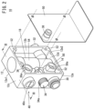
- time delay valve 10 Next, a specific structure of the time delay valve 10 will be described with reference to FIGS. 2 to 4 .
- the main body 12 of the time delay valve 10 is formed in a rectangular frame shape in which a front part 12a, a back part 12b, a top part 12c, and a bottom part 12d are integrated, and both side portions thereof are opening portions 12e1 and 12e2.
- a plurality of bosses 52 for attaching side plates 50 are provided at predetermined positions of the front part 12a, the back part 12b, the top part 12c, and the bottom part 12d of the main body 12.
- Another time delay valve 10 may be connected through the opening portions 12e1 and 12e2.
- a pair of side plates 50 are attached so as to cover the opening portions 12e1 and 12e2 on the side portions.
- the first connection port 30, a flow rate adjustment knob 34a of the first throttle valve 34, and an adjustment knob 40c of the delay throttle valve 40 are disposed on the front part 12a of the main body 12.
- the second connection port 32 is provided on the back part 12b.
- a substantially cylindrical valve housing portion 54 is provided between the top part 12c and the bottom part 12d of the main body 12.
- the switching valve 18 is housed in the valve housing portion 54.
- the first flow path 14 extends from the first connection port 30 on the front part 12a toward the valve housing portion 54.
- Connection ports 56 extend laterally from side portions of the first flow path 14.
- Each of the connection ports 56 is formed in a cylindrical shape and extends to a side portion on an opening portion 12e1 side and a side portion on an opening portion 12e2 side.
- a sealing wall 56a is provided in each of the side portion of the connection port 56 on the opening portion 12e1 side and an inner portion thereof on the opening portion 12e2 side.
- connection ports 56 are sealed by the sealing walls 56a.
- the first throttle valve 34 is connected to the valve housing portion 54 at a position closer to the top part 12c than the first flow path 14 is.
- the flow rate adjustment knob 34a is provided on the front part 12a, and the flow rate of the second flow path 16 can be adjusted by the flow rate adjustment knob 34a.
- the delay throttle valve 40 is connected to the valve housing portion 54 at a position closer to the top part 12c than the first throttle valve 34 is.
- the pilot flow paths 36 are connected to side portions of the delay throttle valve 40.
- the pilot flow paths 36 are connected to the valve housing portion 54 via the delay throttle valve 40.
- the pilot flow paths 36 extend in a cylindrical shape toward the opening portion 12e1 side and the opening portion 12e2 side, and a sealing wall 36a is formed on each of the opening portion 12e1 side and the opening portion 12e2 side.
- a hole is drilled in the sealing wall 36a on the opening portion 12e2 side, and the pilot port 38 is connected to the pilot flow path 36 on the opening portion 12e2 side.
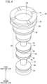
- the switching valve 18 is configured as a spool valve in which a spool 60 is housed inside the valve housing portion 54.
- the valve housing portion 54 has therein a through hole 58 penetrating from the top part 12c to a bottom part 12d side of the main body 12. Both ends of the through hole 58 are sealed with end caps 64, 66.
- the spool 60 and a sleeve 62 housing the spool 60 are accommodated in the through hole 58 between the end caps 64 and 66.
- the end cap 64 is fitted into an end portion of the through hole 58 on a top part 12c side.
- a storage chamber 64a for storing the pilot fluid is formed inside the end cap 64.
- the storage chamber 64a communicates with the delay throttle valve 40 through a hole portion 64b and constitutes a part of the volume portion 42 for storing the pilot fluid.
- the sleeve 62 is fitted into the through hole 58 between the end caps 64, 66.
- a sliding hole 62a is formed penetrating from the top part 12c side to the bottom part 12d side.
- the spool 60 is slidably disposed in the sliding hole 62a.
- a drive piston chamber 68 is formed in the end portion of the sleeve 62 on the top part 12c side.
- the drive piston chamber 68 is a portion for housing a drive piston 70 formed at one end of the spool 60.
- the drive piston chamber 68 is partitioned by the drive piston 70 into a first empty chamber 72a on the top part 12c side and a second empty chamber 72b on the bottom part 12d side.
- the first empty chamber 72a of the drive piston chamber 68 communicates with the storage chamber 64a of the end cap 64.
- An opening portion 44a of the compensation flow path 44 is formed in the second empty chamber 72b of the drive piston chamber 68, and the second empty chamber 72b communicates with the compensation flow path 44.
- the sleeve 62 is formed with a first cutout hole 74 communicating with the first throttle valve 34, a second cutout hole 76 communicating with the second connection port 32, and a third cutout hole 78 communicating with the first flow path 14.
- the first cutout hole 74, the second cutout hole 76, and the third cutout hole 78 are formed to penetrate through the sleeve 62 in a thickness direction.
- a return piston chamber 82 for slidably housing a return piston 80 is formed at an end portion of the sleeve 62 on the bottom part 12d side.
- the return piston chamber 82 is sealed by the end cap 66 fitted into the through hole 58 from the bottom part 12d side.
- the return piston chamber 82 is partitioned by the return piston 80 into an empty chamber on the end cap 66 side and an empty chamber on the top part 12c side.
- An empty chamber of the return piston chamber 82 on the end cap 66 side communicates with the first flow path 14 via a fourth cutout hole 86 constituting the return flow path 46.
- An empty chamber of the return piston chamber 82 on the top part 12c side communicates with the first flow path 14.
- the return piston 80 is formed at an end portion of the spool 60 on the bottom part 12d side, and an end surface of the return piston 80 serves as a fourth pressure receiving surface 80a.
- the fourth pressure receiving surface 80a receives the supply pressure of the control target fluid flowing into the return piston chamber 82 through the return flow path 46, and generates a biasing force that urges the spool 60 toward the first position.
- the biasing member 20 is housed in an empty chamber between the return piston 80 and the end cap 66 in the return piston chamber 82.
- the biasing member 20 is, for example, a spring in the shape of a coil, and is in contact with the fourth pressure receiving surface 80a of the return piston 80.
- the biasing member 20 urges the fourth pressure receiving surface 80a (spool 60) toward the first position on the top part 12c side by its elastic force.
- the elastic force (biasing force) of the biasing member 20 is set to a value greater than the weight of the spool 60, and prevents the spool 60 from moving toward the bottom part 12d side (second position side) when not in use, i.e., when neither the pilot fluid nor the control target fluid is supplied.
- the drive piston 70 is formed at one end of the spool 60 on the first position side (top part 12c side).
- An end surface of the drive piston 70 serves as a first pressure receiving surface 70a, and generates a biasing force that biases the spool 60 toward the second position upon receiving a supply force of the pilot fluid.
- a sliding portion 88 having a diameter smaller than that of the drive piston 70 is formed on the second position side of the drive piston 70. Further, a second pressure receiving surface 70b is formed at a stepped portion between the sliding portion 88 and the drive piston 70. The second pressure receiving surface 70b is formed on an opposite side from the first pressure receiving surface 70a, and generates a biasing force that biases the spool 60 toward the first position by receiving the supply force of the pilot fluid. The second pressure receiving surface 70b constitutes a part of the compensation mechanism 26.
- the biasing force of the first pressure receiving surface 70a exceeds the biasing forces of the second pressure receiving surface 70b and the biasing member 20.
- the sliding portion 88 extends toward the second position side (bottom part 12d side).
- the sliding portion 88 is formed with a first recessed portion 90, a first partition wall 92, a second recessed portion 94, a second partition wall 96, a third recessed portion 98, and the return piston 80 in this order from the first position side.
- a plurality of packing housing grooves 99 are formed in predetermined portions of the spool 60. As shown in FIG. 3 , an O-ring 97 is mounted in each of the packing housing grooves 99 to seal a gap between the spool 60 and the sleeve 62.
- the first recessed portion 90 communicates with the first cutout hole 74
- the second recessed portion 94 communicates with the second cutout hole 76
- the third recessed portion 98 communicates with the third cutout hole 78.
- the first partition wall 92 air-tightly (liquidtightly) partitions the first cutout hole 74 and the second cutout hole 76.
- the second partition wall 96 is disposed at the position of the second cutout hole 76, and the second cutout hole 76 and the third cutout hole 78 communicate with each other through the third recessed portion 98.
- the first connection port 30 and the second connection port 32 are connected to each other through the first flow path 14.
- the first partition wall 92 is disposed at the position of the second cutout hole 76, and the first cutout hole 74 and the second cutout hole 76 communicate with each other through the first recessed portion 90.
- the second partition wall 96 comes into close contact with an inner peripheral surface of the sleeve 62 between the second cutout hole 76 and the third cutout hole 78, and communication between the second cutout hole 76 and the third cutout hole 78 is blocked.
- the first connection port 30 and the second connection port 32 are connected through the second flow path 16 and the first throttle valve 34.
- the time delay valve 10 according to the present embodiment is configured as described above, and the operation thereof will be described below.
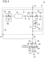
- the time delay valve 10 is connected to an operation switching valve 100 and is used as a driving device for a fluid pressure device such as an air cylinder.
- the illustrated fluid circuit is a fluid circuit in which the flow rate of the control target fluid discharged from a fluid discharge unit 114 is throttled after a predetermined delay time using the time delay valve 10.
- the operation switching valve 100 is a five-port valve and has ports 102 to 110.
- the pilot port 38 is connected to the first port 102, and the first connection port 30 is connected to the second port 104.
- the fluid discharge unit 114 is connected to the third port 106 and the fifth port 110, and a fluid supply source 112 is connected to the fourth port 108.
- the fluid supply source 112 is, for example, a pressure line, an air compressor or the like in a factory.
- the operation switching valve 100 is switched between a first position and a second position.
- the first port 102 and the fourth port 108 are connected to each other, and the second port 104 and the fifth port 110 are connected to each other. That is, the fluid supply source 112 is connected to the pilot port 38 to supply the pilot fluid, and the fluid discharge unit 114 is connected to the first connection port 30. Then, the pilot fluid is supplied to the pilot flow path 36 through the pilot port 38.
- the switching valve 18 is disposed at the first position by the biasing force of the biasing member 20, and the first connection port 30 and the second connection port 32 communicate with each other through the first flow path 14.
- a part of the pilot fluid flows into the compensation mechanism 26 through the compensation flow path 44 branched from the pilot flow path 36.
- Another part of the pilot fluid flows into the volume portion 42 (storage chamber 64a) at a predetermined flow rate through the delay throttle valve 40 to gradually increase the pressure of the pilot fluid acting on the drive mechanism 22.
- the spool 60 (the switching valve 18) is switched to the second position at timing when the biasing force 2 in the second position direction becomes larger than a combined force of the biasing force 1 in the first position direction and the biasing force 3.
- the switching valve 18 When the switching valve 18 is switched to the second position, the first connection port 30 and the second connection port 32 shown in FIG. 5 are connected to each other through the second flow path 16, and the flow rate of the control target fluid is regulated by the first throttle valve 34.
- the time delay valve 10 operates such that the switching valve 18 is switched after a predetermined delay time elapses from the supply of the pilot fluid.
- the biasing force 1 is generated by applying the supply pressure of the pilot fluid to the second pressure receiving surface 70b, prior to the increase of the biasing force 2. Since the magnitude of the biasing force 1 is proportional to the pressure of the pilot fluid, the biasing force 1 acts to compensate the increasing speed of the biasing force 2. That is, as the pressure of the fluid supply source 112 increases, the biasing force 1 increases accordingly. Then, the magnitude of the biasing force 2 required for switching the spool 60 increases, and the influence of the increase in the increasing speed of the urging force 2 is cancelled, so that it is possible to suppress the variation of the switching timing (delay time) of the spool 60.
- the supply pressure of the pilot fluid acting on the second pressure receiving surface 70b also decreases.
- the biasing force 1 decreases, and the spool 60 can be switched with a smaller biasing force 2.
- the influence due to the decrease in the increase rate of the biasing force 2 is canceled out, and the variation in the switching timing (delay time) of the spool 60 can be suppressed.
- the time delay valve 10 of the present embodiment can stabilize the timing of the switching operation of the spool 60 even in the return operation.
- the operation switching valve 100 shown in FIG. 5 is switched to the second position, the first port 102 and the third port 106 are connected, and the second port 104 and the fourth port 108 are connected. That is, the fluid supply source 112 is connected to the first connection port 30 of the time delay valve 10, and the fluid discharge unit 114 is connected to the pilot port 38.
- the pilot fluid stored in the volume portion 42 is discharged from the fluid discharge unit 114 via the check valve 40b and the pilot flow path 36. Then, the spool 60 (the switching valve 18) returns to the first position at timing when the pressure of the pilot fluid acting on the drive mechanism 22 falls below the predetermined value and the biasing force 2 in FIG. 6 falls below the biasing force 3 of the biasing member 20. However, since the amount of the pilot fluid stored in the volume portion 42 increases or decreases in accordance with the pressure fluctuation of the fluid supply source 112 which is the supply pressure of the pilot fluid, the timing at which the spool 60 (the switching valve 18) returns to the first position is affected by the pressure of the fluid supply source 112.
- a part of the control target fluid in the first connection port 30 is supplied to the return piston chamber 82 of the return mechanism 28 through the return flow path 46 communicating with the first connection port 30.
- the return piston 80 of the return mechanism 28 generates a biasing force toward the second position with a magnitude corresponding to the supply pressure of the control target fluid (the pressure of the fluid supply source 112). Since the biasing force of the return mechanism 28 is superimposed on the biasing force of the biasing member 20, the biasing force of the return mechanism 28 acts so as to cancel the change in the amount of the pilot fluid stored in the volume portion 42.
- the time delay valve 10 can suppress variation in the timing of the return operation due to the fluctuation in the pressure of the fluid supply source 112.
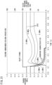
- FIG. 7 is a diagram illustrating a transition of the charge pressure of the pilot air in the volume portion 42 of the time delay valve according to Comparative Example and a state of variation of the switching timing (delay time).
- the compensation flow path 44 of FIG. 6 is opened to the atmosphere so that the biasing force 1 corresponding to the pressure of the pilot fluid is not generated.
- the time delay valve 10 of the present embodiment has the following effects.
- the time delay valve 10 includes the switching valve 18 configured to be switched between the first position and the second position; the biasing member 20 configured to bias the switching valve 18 toward the first position; the drive mechanism 22 configured to bias the switching valve 18 toward the second position under the action of the supply pressure of the pilot fluid; the pilot flow path 36 configured to guide the pilot fluid to the drive mechanism 22; and the delay mechanism 24 configured to delay switching timing of the switching valve 18, wherein the delay mechanism 24 includes: the delay throttle valve 40 provided in the pilot flow path 36; and the compensation mechanism 26 configured to bias the switching valve 18 toward the first position under the action of the supply pressure of the pilot fluid.
- the biasing force 1 (see FIG. 6 ) corresponding to the pressure of the pilot fluid can be applied to the switching valve 18 by the compensation mechanism 26.
- the supply pressure of the pilot fluid can change the biasing force 2 of the drive mechanism 22 when the switching valve 18 is switched from the first position to the second position, and the variation width of the delay time due to the fluctuation in the supply pressure of the pilot fluid can be suppressed.
- the compensation mechanism 26 may include a piston mechanism configured to generate a biasing force opposite to that of the drive mechanism 22 under the action of the supply pressure of the pilot fluid. In accordance with this configuration, it is possible to generate the biasing force 1 corresponding to the supply pressure of the pilot fluid.
- the compensation mechanism 26 is supplied with the pilot fluid through the compensation flow path 44 branched from the pilot flow path 36 on the upstream side of the delay throttle valve 40.
- the supply pressure of the pilot fluid can be quickly applied to the compensation mechanism 26, and the switching timing of the switching valve 18 can be stabilized.
- the time delay valve 10 described above may further include the first flow path 14 configured to allow communication at the first position of the switching valve 18, the second flow path 16 configured to allow communication at the second position of the switching valve 18, and the first throttle valve 34 provided in at least one of the first flow path 14 or the second flow path 16. According to this configuration, the flow rate of the control target fluid can be switched.
- the time delay valve 10 described above may further include the return mechanism 28 configured to generate a biasing force opposite to that of the drive mechanism 22, and the return flow path 46 branched from the first flow path 14 or the second flow path 16 and connected to the return mechanism 28. According to this configuration, even when the supply pressure of the pilot fluid fluctuates, the timing of the return operation of the switching valve 18 can be stabilized.
- the switching valve 18 includes the spool 60 and the sleeve 62 in which the spool 60 slides
- the drive mechanism 22 includes the drive piston chamber 68 provided at one end of the spool 60 and the drive piston 70 configured to partition the drive piston chamber 68 into the first empty chamber 72a on the first position side and the second empty chamber 72b on the second position side
- the drive piston 70 includes the first pressure receiving surface 70a on a side of the first empty chamber 72a, the first pressure receiving surface 70a being configured to receive the supply pressure of the pilot fluid to generate the biasing force on the second position side.
- the drive piston 70 may be formed integrally with the spool 60, and the compensation mechanism 26 may include in the drive piston 70 the second pressure receiving surface 70b that faces the second empty chamber 72b and is provided on an opposite side from the first pressure receiving surface 70a. According to this configuration, since the compensation mechanism 26 is provided in the drive piston 70, the device configuration is simplified.
- the area of the second pressure receiving surface 70b is smaller than the area of the first pressure receiving surface 70a.
- the pilot fluid can generate a biasing force for switching the switching valve 18 from the first position to the second position.
- the return mechanism 28 may include the return piston 80 formed at the other end of the spool 60 and the return piston chamber 82 configured to house the return piston 80. According to this configuration, the return piston 80 of the return mechanism 28 is integrated with the spool 60, and the device configuration is simplified.
- the biasing member 20 may be disposed in the return piston chamber 82. According to this configuration, the time delay valve 10 can be miniaturized.
- a time delay valve 11 does not have the second flow path 16 inside a main body 12A, and the second flow path 16 and the first throttle valve 34 are externally provided.
- the same components as those of the time delay valve 10 described with reference to FIGS. 1 to 6 are designated by the same reference numerals, and detailed description of such features will be omitted.
- the time delay valve 11 has the first flow path 14 that connects the first connection port 30 and the second connection port 32 of the main body 12A, and a switching valve 18A is provided in the first flow path 14.
- the switching valve 18A is switchable between a first position and a second position. In the first position, the switching valve 18A allows the fluid in the first flow path 14 to flow therethrough, and prevents the fluid in the first flow path 14 from allowing therethrough, in the second position.
- the switching valve 18A is biased to the first position by the biasing member 20.
- the switching valve 18A is switched to the second position after a predetermined delay period (delay time) has elapsed, and the passage of the control target fluid through the first flow path 14 is blocked.
- the flow rate of the control target fluid can be throttled after the lapse of a predetermined delay time, and the same function as that of the time delay valve 10 can be obtained.
- the time delay valve 11 of the present modification can suppress variation of the switching timing (delay time) due to fluctuation of the supply pressure of the pilot fluid.
- the switching valve 18A of the time delay valve 11 is not limited to a two-port valve, but may be a five-port valve or the like.
- the device provided in the second flow path 16 is not limited to the first throttle valve 34, and various devices may be connected in place of the first throttle valve 34.
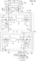
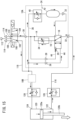
- the flow rate controller 150 uses the time delay valve 10 according to the first embodiment.
- the flow rate controller 150 constitutes a fluid circuit for driving a fluid pressure cylinder 120.
- the flow rate controller 150 includes a first module 10A and a second module 10B, both of which have the same structure as that of the time delay valve 10 of FIG. 1 .
- the same components as those of the time delay valve 10 of FIG. 1 are designated by the same reference numerals, and detailed description of such features will be omitted.
- the fluid pressure cylinder 120 is a double acting type cylinder, and a piston 120a is provided inside a cylinder chamber 121.
- the piston 120a divides the cylinder chamber 121 of the fluid pressure cylinder 120 into a head-side empty chamber 121a and a rod-side empty chamber 121b. Fluid is supplied to and discharged from the head-side empty chamber 121a through a head-side port 122, and fluid is supplied to and discharged from the rod-side empty chamber 121b through a rod-side port 124.
- the piston 120a is displaced in the axial direction while sliding on the inner wall of the cylinder chamber 121 by the fluid (control target fluid) supplied to and discharged from the head-side port 122 and the rod-side port 124.
- a piston rod 120b is connected to the piston 120a, and the piston rod 120b is displaced integrally with the piston 120a.
- the flow rate controller 150 has a function of performing two-stage speed control for switching the speed of the piston 120a (and the piston rod 120b) of the fluid pressure cylinder 120 from a first speed which is a higher speed to a second speed which is a lower speed.
- the flow rate controller 150 can be suitably used when it is required to reduce the impact at the stroke end of the fluid pressure cylinder 120 and to shorten the cycle time by realizing a high-speed operation.
- the specific structure of the flow rate controller 150 will be described.
- the flow rate controller 150 includes a first supply and discharge path 116 connected to the head-side port 122, a second supply and discharge path 118 connected to the rod-side port 124, the operation switching valve 100 that switches and connects the fluid supply source 112 and the fluid discharge unit 114 to the first supply and discharge path 116 and the second supply and discharge path 118, speed adjusting units 126 and 128 that regulate the first operation speed of the fluid pressure cylinder 120, and the first module 10A and the second module 10B that regulate the second operation speed.
- the first speed and the second module 10B are connected to the first supply and discharge path 116.
- the first speed adjusting unit 126 is a member that regulates an operation speed at the high first speed in a return stroke in which the piston rod 120b of the fluid pressure cylinder 120 is pulled in.
- the first speed includes a check valve 126a and a throttle valve 126b.
- the check valve 126a is connected in parallel with the throttle valve 126b in such a direction as to allow the fluid supplied to the fluid pressure cylinder 120 to pass therethrough without resistance.
- the first speed adjusting unit 126 regulates the operation speed of the fluid pressure cylinder 120 by throttling the flow rate of the fluid discharged from the head-side port 122 by the throttle valve 126b. That is, the first speed adjusting unit 126 constitutes a meter-out speed controller that regulates the operation speed by the fluid discharged from the fluid pressure cylinder 120.
- the second module 10B is connected between the first speed adjusting unit 126 and the operation switching valve 100 in the first supply and discharge path 116.
- the second connection port 32 is connected to the first speed adjusting unit 126
- the first connection port 30 is connected to the operation switching valve 100.
- the second module 10B switches the flow path of the control target fluid from the first flow path 14 to the second flow path 16 to reduce the flow rate of the control target fluid, thereby setting to the operation speed to the low second speed.
- the pilot flow path 36 of the second module 10B is connected to the second supply and discharge path 118 via a second intersection flow path 130B. That is, the pilot fluid of the second module 10B is supplied from the second supply and discharge path 118 on the opposite side.
- the second speed adjusting unit 128 and the first module 10A are connected to the second supply and discharge path 118.
- the second speed adjusting unit 128 is configured in the same manner as the first speed adjusting unit 126, and configures a meter-out speed controller that allows the flow in the direction of being supplied to the fluid pressure cylinder 120 to pass therethrough without resistance and regulates the flow in the opposite direction.
- the second speed adjusting unit 128 regulates an operation speed at the high first speed in a drive stroke in which the piston rod 120b of the fluid pressure cylinder 120 is extended.
- the first module 10A is connected between the second speed adjusting unit 128 and the operation switching valve 100 in the second supply and discharge path 118.
- the configuration of the first module 10A is similar to that of the second module 10B.
- the pilot flow path 36 of the first module 10A is connected to the first supply and discharge path 116 via a first intersection flow path 130A.
- the pilot flow paths 36 of the first module 10A and the second module 10B are connected to the supply and discharge paths 116 and 118, respectively, on the opposite sides so as to cross each other.
- first speed adjusting unit 126 and the second speed adjusting unit 128 are not limited to meter-out speed controllers, and may be configured as meter-in speed controllers by connecting the check valves 126a and 128a in opposite directions.
- the operation switching valve 100 is similar to the operation switching valve 100 described with reference to FIG. 5 .
- the first port 102 of the operation switching valve 100 is connected to the second supply and discharge path 118
- the second port 104 is connected to the first supply and discharge path 116
- the third port 106 and the fifth port 110 are connected to the fluid discharge unit 114
- the fourth port 108 is connected to the fluid supply source 112.
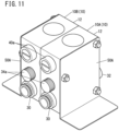
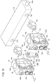
- the circuit configuration of the flow rate controller 150 according to the present embodiment is as described above. Further, the first module 10A and the second module 10B may be configured as an integrated valve unit 140. Hereinafter, the valve unit 140 will be described with reference to FIGS. 11 and 12 .
- the valve unit 140 is configured by connecting two modules, i.e., the first module 10A and the second module 10B, each having the body 12.
- the internal configuration of each of the first module 10A and the second module 10B is the same as that of the time delay valve 10 in FIG. 2 .
- a flow path connecting member 130 is provided in order to connect the pilot flow paths 36 of the first module 10A and the second module 10B to the supply and discharge paths 116 and 118 on the opposite side so as to cross each other.
- the flow path connecting member 130 includes the first intersection flow path 130A that connects the connection port 56 of the second module 10B and the pilot flow path 36 of the first module 10A, and the second intersection flow path 130B that connects the connection port 56 of the first module 10A and the pilot flow path 36 of the second module 10B.
- the flow path connecting member 130 is connected to the pilot flow paths 36 so as to be sandwiched between the first intersection flow path 130A and the second intersection flow path 130B.
- respective holes are drilled in the sealing wall 56a of the connection port 56 on an opening portion 12e2 side and the sealing wall 36a of the pilot flow path 36 on the opening portion 12e2 side.
- respective holes are drilled in the sealing wall 56a of the connection port 56 on an opening portion 12e1 side and the sealing wall 36a of the pilot flow path 36 on the opening portion 12e1 side.
- both side portions of the first module 10A and the second module 10B are covered with side plates 50A, and connected by bolts.
- a sealing member (not shown) is provided at a portion of the side plate 50A corresponding to the pilot flow path 36, and the opening portion of the pilot flow path 36 is sealed by the side plate 50A.
- the flow rate controller 150 according to the present embodiment is configured as described above, and the operations and actions will be described below.
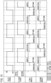
- the horizontal axis indicates the passage of time, and the operation of controlling the flow rate of the control target fluid is performed in accordance with the switching operation of the operation switching valve 100.
- a valve signal indicates the switching state of the operation switching valve 100 of the flow rate controller 150. In an “ON” state, the first supply and discharge path 116 is connected to the fluid supply source 112, and in an “OFF” state, the second supply and discharge path 118 is connected to the fluid supply source 112.
- a cylinder stroke indicates a stroke direction of the fluid pressure cylinder 120
- "DRIVE” indicates that a drive stroke for extending the piston rod 120b is performed
- "RETURN” indicates that a return stroke for pulling in the piston rod 120b is performed.
- the first port 102 and the fourth port 108 of the operation switching valve 100 are connected to each other, and the second supply and discharge path 118 is connected to the fluid supply source 112.
- the control target fluid is supplied to the fluid pressure cylinder 120 via the second module 10B to start the drive stroke.
- the operation of the first supply and discharge path 116 and the second module 10B during the drive stroke is the same as the operation of the first module 10A of the second supply and discharge path 118 during the return stroke described with reference to FIGS. 18 and 19 , and thus the description thereof is omitted here.
- the switching valve 18 of the first module 10A is located at the first position which is the initial position, and the pilot fluid is released from the drive mechanism 22 and the volume portion 42.
- the flow path of the control target fluid in the first module 10A is the first flow path 14, and the flow rate of the fluid discharged via the first supply and discharge path 116 is regulated only by the first speed adjusting unit 126.
- the pilot fluid in the first supply and discharge path 116 flows into the pilot flow path 36 through the first intersection flow path 130A.
- a portion of the pilot fluid is supplied to the compensation mechanism 26 through the compensation flow path 44, and the compensation mechanism 26 generates a biasing force having a magnitude corresponding to the supply pressure of the pilot fluid.
- the pilot fluid in the pilot flow path 36 flows into the volume portion 42 while being regulated by the delay throttle valve 40, and the pressure of the pilot fluid acting on the drive mechanism 22 gradually increases.
- the switching valve 18 is switched to the second position as shown in FIG. 15 .
- the flow rate of the fluid discharged via the first supply and discharge path 116 is further throttled by the first throttle valve 34 provided in the second flow path 16 of the first module 10A in addition to the second speed adjusting unit 128.
- the operation speed of the fluid pressure cylinder 120 is switched to the low second speed.
- Comparative Example 2 shown in FIG. 16 shows a result of a case where the flow rate controller is configured by a time delay valve not including the compensation mechanism 26. Attention is paid to the loci of the fluid pressure cylinder 120 when the flow rate controller of Comparative Example 2 is used.
- the delay throttle valve 40 is adjusted so that the pressure of the fluid supply source 112 becomes optimum at 0.4 MPa. However, if the fluid supply source 112 increases or decreases by ⁇ 0.1 MPa, the adjustment becomes improper, causing bouncing or the like at the end of the stroke of the fluid pressure cylinder 120 and increasing the variation in the timing of the end of the stroke. As described above, in the flow rate controller of Comparative Example 2 that does not include the compensation mechanism 26, the variation in the stroke end time of the fluid pressure cylinder 120 becomes large.
- the fluid pressure cylinder 120 is used by being incorporated in a production line of a factory. If the variation in the stroke end time of the fluid pressure cylinder 120 is large, there is a concern that interference may occur between a member connected to the fluid pressure cylinder 120 and other devices. From the viewpoint of preventing such interference, it is necessary to provide a relatively large safety margin when setting the valve signal for operating the fluid pressure cylinder 120. As a result, the cycle time of the fluid pressure cylinder 120 is increased.
- a step appears near 0.4 seconds in each of the charging characteristics of the first module 10A.
- This step is caused by the movement of the spool 60 of the switching valve 18, and indicates the timing at which the switching valve 18 of the first module 10A switches.
- the time at which the steps of the charging characteristics occur hardly change from 0.3 MPa to 0.5 MPa, and it is understood that the variation of the delay time is suppressed.
- the second supply and discharge path 118 is connected to the fluid discharge unit 114, and the first supply and discharge path 116 is connected to the fluid supply source 112.
- the operation of the first supply and discharge path 116 and the second module 10B is the same as the operation of the first module 10A described with reference to FIGS. 14 and 15 , and the description thereof will be omitted.
- the volume portion 42 of the first module 10A is charged with the pilot fluid, and the switching valve 18 is held at the second position by the action of the biasing force of the drive mechanism 22.
- the pilot fluid charged in the compensation mechanism 26 and the volume portion 42 is discharged to the first supply and discharge path 116.
- a part of the control target fluid in the second supply and discharge path 118 flows into the return mechanism 28 through the return flow path 46.
- the switching valve 18 returns to the first position as shown in FIG. 19 .
- the control target fluid is supplied to the fluid pressure cylinder 120 through the second module 10B, and the stroke of the fluid pressure cylinder 120 is started.
- the stroke of the fluid pressure cylinder 120 is started at the timing at which the switching valve 18 returns to the first position, if the return timing of the switching valve 18 varies, the stroke of the fluid pressure cylinder 120 varies.
- the amount of pilot fluid charged in the volume portion 42 increases or decreases in accordance with the supply pressure of the fluid supply source 112.
- the biasing force corresponding to the supply pressure of the fluid supply source 112 is added to the biasing force of the biasing member 20 through the return mechanism 28, it is possible to cancel the influence of the increase or decrease in the amount of the pilot fluid charged in the volume portion 42 by the return mechanism 28.
- the pilot pressure of the volume portion 42 tends to decrease earlier in the order of 0.3 MPa, 0.4 MPa, and 0.5 MPa for the pressure of the fluid supply source 112.
- the loci of the fluid pressure cylinder 120 rise after a delay time ranging from 0.15 seconds to 0.25 seconds after the valve signal is switched.
- the start timing of the stroke of the fluid pressure cylinder 120 is greatly affected by the fluid supply source 112.
- the loci of the fluid pressure cylinder 120 rise about 0.25 seconds after the valve signal is switched, and it can be seen that the delay time until the start of the stroke of the fluid pressure cylinder 120 is shorter than that of Comparative Example 3.
- the supply pressure of the fluid supply source 112 changes in the range of 0.3 to 0.5 MPa, the rising time of each of the loci does not change, and it can be seen that the start timing of the stroke of the fluid pressure cylinder 120 is not affected by the pressure fluctuation of the fluid supply source 112.
- the delay time until the start of the stroke of the fluid pressure cylinder 120 can be shortened, and that the variation in the stroke start timing of the fluid pressure cylinder 120 can be suppressed even when the supply pressure of the fluid supply source 112 fluctuates. Therefore, according to the flow rate controller 150 of the present embodiment, it is possible to shorten the waiting time set in the valve signal and to shorten the cycle time.
- the flow rate controller 150 of the present embodiment realizes the following advantageous effects.
- the flow rate controller 150 includes the first supply and discharge path 116 configured to supply and discharge fluid to and from the head-side port (one port) 122 of the fluid pressure cylinder 120, the second supply and discharge path 118 configured to supply and discharge fluid to and from rod-side port (another port) 124 of the fluid pressure cylinder 120, the operation switching valve 100 configured to switch and connect the fluid supply source 112 and the fluid discharge unit 114 to the first supply and discharge path 116 and the second supply and discharge path 118, the fluid supply source 112 being configured to supply the control target fluid and the fluid discharge unit 114 being configured to discharge fluid, and the time delay valves (first module 10A and second module 10B) provided in the first supply and discharge path 116 and the second supply and discharge path 118, respectively, wherein each of the time delay valves (first module 10A and second module 10B) includes the switching valve 18 configured to be switched between the first position and the second position, the biasing member 20 configured to bias the switching valve 18 toward the first position, the drive mechanism 22 configured to bias the switching valve 18 toward the
- the pilot flow path 36 of the second module 10B (time delay valve) of the first supply and discharge path 116 may be connected to the second supply and discharge path 118
- the pilot flow path 36 of the first module 10A (time delay valve) of the second supply and discharge path 118 may be connected to the first supply and discharge path 116.
- the device configuration of the flow rate controller 150 can be simplified.
Landscapes
- Engineering & Computer Science (AREA)
- General Engineering & Computer Science (AREA)
- Physics & Mathematics (AREA)
- Mechanical Engineering (AREA)
- Fluid Mechanics (AREA)
- Analytical Chemistry (AREA)
- Chemical & Material Sciences (AREA)
- General Physics & Mathematics (AREA)
- Automation & Control Theory (AREA)
- Fluid-Driven Valves (AREA)
- Fluid-Pressure Circuits (AREA)
- Multiple-Way Valves (AREA)
- Flow Control (AREA)
Abstract
Description
- The present invention relates to a time delay valve and a flow rate controller for performing a delay operation in a fluid circuit.
- Conventionally, various valves (time delay valves) for performing a delay operation have been proposed. Such a time delay valve is used, for example, for two-stage speed control in which a fluid pressure cylinder operated by fluid pressure is switched from a first speed (high speed) to a second speed (low speed). Such two-stage speed control is effective in reducing the impact at the stroke end of the fluid pressure cylinder, shortening the cycle time by increasing the operation speed, and the like.
- Various time delay valves have been proposed which utilize the supply pressure of a pilot fluid to operate the valve. In this case, a throttle and a volume portion are used in the delay mechanism, and the switching operation of the valve is performed at the timing when a predetermined amount of pilot fluid is supplied to the volume portion (for example,
JP 5632914 B2 JP 4595411 B2 JP 3161965 B2 JP 2001-050204 A JP 5578502 B2 JP 5756984 B1 - However, the conventional time delay valve has a problem that when the supply pressure of the pilot fluid fluctuates, the flow rate of the pilot fluid passing through the throttle of the delay mechanism fluctuates and the timing at which the valve is switched varies.
- Therefore, when the time delay valve is used in a place where the pressure tends to fluctuate, such as a pressure line in a factory, the switching timing of the time delay valve varies. As a result, since the operation time of each of the devices using the time delay valve varies, it is necessary to provide a predetermined waiting time in consideration of the variation in the operation of devices, which causes a problem that the cycle time is prolonged.
- Therefore, it is an object of the present invention to provide a time delay valve and a flow rate controller capable of suppressing the influence on the switching timing due to the fluctuation of the supply pressure of the pilot fluid.
- According to one aspect of the present disclosure, there is provided a time delay valve including a switching valve configured to be switched between a first position and a second position, a biasing member configured to bias the switching valve toward the first position, a drive mechanism configured to bias the switching valve toward the second position under an action of a supply pressure of a pilot fluid, a pilot flow path configured to guide the pilot fluid to the drive mechanism, and a delay mechanism configured to delay switching timing of the switching valve, wherein the delay mechanism includes a delay throttle valve provided in the pilot flow path, and a compensation mechanism configured to bias the switching valve toward the first position under an action of the supply pressure of the pilot fluid.
- According to another aspect, there is provided a flow rate controller including a first supply and discharge path configured to supply and discharge fluid to and from one port of a fluid pressure cylinder, a second supply and discharge path configured to supply and discharge fluid to and from another port of the fluid pressure cylinder, an operation switching valve configured to switch and connect a fluid supply source and a fluid discharge unit to the first supply and discharge path and the second supply and discharge path, the fluid supply source being configured to supply a control target fluid and the fluid discharge unit being configured to discharge fluid, and time delay valves provided in the first supply and discharge path and the second supply and discharge path, respectively, wherein each of the time delay valves includes a switching valve configured to be switched between a first position and a second position, a biasing member configured to bias the switching valve toward the first position, a drive mechanism configured to bias the switching valve toward the second position under an action of a supply pressure of a pilot fluid, a pilot flow path configured to guide the pilot fluid to the drive mechanism, and a delay mechanism configured to delay switching timing of the switching valve, and wherein the delay mechanism includes a first throttle valve provided in the pilot flow path, and a compensation mechanism configured to bias the switching valve toward the first position under an action of the supply pressure of the pilot fluid.
- According to the time delay valve and the flow rate controller of the above-described aspects, it is possible to suppress the influence on the switching timing due to the fluctuation of the supply pressure of the pilot fluid.
-
-
FIG. 1 is a fluid circuit diagram of a time delay valve according to a first embodiment; -
FIG. 2 is a perspective view of the time delay valve ofFIG. 1 ; -
FIG. 3 is a cross-sectional view of the time delay valve ofFIG. 2 taken along line III-III; -
FIG. 4 is a perspective view of a spool ofFIG. 3 ; -
FIG. 5 is a fluid circuit diagram illustrating an example of connection of a drive circuit to the time delay valve ofFIG. 1 ; -
FIG. 6 is an explanatory diagram illustrating the operation of the time delay valve ofFIG. 1 ; -
FIG. 7 is a graph illustrating the influence on the delay time (switching timing) by the fluctuation in the charge pressure of the pilot air of the time delay valve according to Comparative Example; -
FIG. 8 is a graph showing the influence on the delay time (switching timing) by the fluctuation in the charge pressure of the pilot air of the time delay valve according to the first embodiment; -
FIG. 9 is a fluid circuit diagram of a time delay valve according to a modification of the first embodiment; -
FIG. 10 is a fluid circuit diagram of a flow rate controller according to a second embodiment; -
FIG. 11 is a perspective view of the flow rate controller according to the second embodiment; -
FIG. 12 is a schematic diagram illustrating an example of connection arrangement to the flow rate controller ofFIG. 11 and a fluid pressure cylinder; -
FIG. 13 is a timing chart illustrating the operation of the flow rate controller ofFIG. 10 ; -
FIG. 14 is a fluid circuit diagram illustrating the operation of the first module of the flow rate controller ofFIG. 10 (part 1); -
FIG. 15 is a fluid circuit diagram illustrating the operation of the first module of the flow rate controller ofFIG. 10 (part 2); -
FIG. 16 is a graph illustrating loci of a fluid pressure cylinder connected to a flow rate controller according to Comparative Example 2 and charging characteristics of a first module according to Comparative Example 2; -
FIG. 17 is a graph illustrating loci of the fluid pressure cylinder connected to the flow rate controller according to the second embodiment and charging characteristics of the first module according to the second embodiment; -
FIG. 18 is a fluid circuit diagram illustrating the operation of the first module of the flow rate controller ofFIG. 10 (part 3); -
FIG. 19 is a fluid circuit diagram illustrating the operation of the first module of the flow rate controller ofFIG. 10 (part 4); -
FIG. 20 is a graph illustrating return response characteristics of a first module according to Comparative Example 3; and -
FIG. 21 is a graph illustrating return response characteristics of the first module ofFIG. 10 . - A preferred embodiment of a time delay valve and a flow rate controller according to the present invention will be described in detail below with reference to the accompanying drawings.
- A
time delay valve 10 of the present embodiment shown inFIGS. 1 and2 is mounted on a cylinder or a drive circuit of various fluid pressure devices, and is used for a pneumatic device or the like in a production line of a factory. Thetime delay valve 10 is used to control a flow rate of a control target fluid such as air. The control target fluid and the pilot fluid are not limited to air. - As shown in
FIG. 1 , thetime delay valve 10 of the present embodiment includes, inside amain body 12, afirst flow path 14, asecond flow path 16, aswitching valve 18, abiasing member 20, adrive mechanism 22, adelay mechanism 24, acompensation mechanism 26, and areturn mechanism 28. Among them, thefirst flow path 14 and thesecond flow path 16 are flow paths through which the control target fluid flows, and are flow paths that connect afirst connection port 30 and asecond connection port 32 of themain body 12. - The
first flow path 14 and thesecond flow path 16 are flow paths provided in parallel, and a path through which the control target fluid flows is selectively switched between these flow paths, by a switching operation of theswitching valve 18. Thesecond flow path 16 is provided with afirst throttle valve 34 for throttling a flow rate so as to pass the control target fluid under a condition different from that of thefirst flow path 14. Thefirst throttle valve 34 may be provided in thefirst flow path 14 instead of thesecond flow path 16. Alternatively, thefirst throttle valve 34 may be provided in both thefirst flow path 14 and thesecond flow path 16. Further, thefirst throttle valve 34 is not limited to a variable throttle valve having a variable flow rate, but may be a fixed throttle valve that allows a fluid to pass therethrough at a constant flow rate. - The
switching valve 18 is configured as a three-port valve that can be switched between a first position and a second position. At the first position, theswitching valve 18 causes thefirst connection port 30 and thesecond connection port 32 to communicate with each other via thefirst flow path 14. At the second position, theswitching valve 18 causes thefirst connection port 30 and thesecond connection port 32 to communicate with each other via thesecond flow path 16. Theswitching valve 18 is configured to be switched between the first position and the second position by the biasing force of thebiasing member 20, thedrive mechanism 22, thecompensation mechanism 26, and thereturn mechanism 28. - The
biasing member 20 is a member that biases theswitching valve 18 toward the first position, and is configured by, for example, an elastic member such as a spring or rubber. In a state in which pilot fluid is not supplied to theswitching valve 18, theswitching valve 18 is held at the first position by the biasing force of thebiasing member 20. Thebiasing member 20 has such an elastic force that theswitching valve 18 is not switched to the second position by its own weight. - The
drive mechanism 22 is a member that generates a biasing force that biases theswitching valve 18 toward the second position under the action of the pilot fluid. Thedrive mechanism 22 includes a piston mechanism disposed on an opposite side from thebiasing member 20 as will be described later, and generates a biasing force corresponding to the supply pressure of the pilot fluid. Thedrive mechanism 22 switches theswitching valve 18 to the second position at a timing at which its biasing force exceeds the biasing forces of thebiasing member 20 and thecompensation mechanism 26. - A pilot fluid is supplied to the
drive mechanism 22 via apilot flow path 36. Thepilot flow path 36 is a flow path that connects apilot port 38 of themain body 12 and thedrive mechanism 22, and guides the pilot fluid flowing in from thepilot port 38 to thedrive mechanism 22. - The
delay mechanism 24 includes adelay throttle valve 40 provided in thepilot flow path 36, avolume portion 42 provided downstream of thedelay throttle valve 40, and thecompensation mechanism 26. Thedelay throttle valve 40 is provided with athrottle valve 40a by which flow rate can be varied and acheck valve 40b, in parallel. Thedelay throttle valve 40 can adjust the increase speed of the pressure of the pilot fluid acting on thedrive mechanism 22 by throttling the flow rate of the pilot fluid flowing into thevolume portion 42 via thepilot flow path 36, and can thus adjust the switching timing of the switchingvalve 18. Thevolume portion 42 is configured as a volume of thepilot flow path 36 on the downstream side of thedelay throttle valve 40 and as a volume of the piston mechanism of thedrive mechanism 22. If necessary, a member such as a storage tank may be added. - The
compensation mechanism 26 is a member that generates a biasing force biasing the switchingvalve 18 toward the first position. Thecompensation mechanism 26 is connected to thepilot port 38 via acompensation flow path 44 that branches off from thepilot flow path 36 on the upstream side of thedelay throttle valve 40. Thecompensation mechanism 26 is supplied with the pilot fluid through thecompensation flow path 44. Thecompensation mechanism 26 generates a biasing force toward the first position having a magnitude corresponding to the supply pressure of the pilot fluid. That is, when the supply pressure of the pilot fluid increases, the biasing force of thecompensation mechanism 26 increases. When the supply pressure of the pilot fluid decreases, the biasing force of thecompensation mechanism 26 decreases. However, the biasing force of thecompensation mechanism 26 rises more quickly than the biasing force of thedrive mechanism 22. The biasing force that defines the timing at which the switchingvalve 18 is switched is increased or decreased in accordance with the supply pressure of the pilot fluid. - The
return mechanism 28 is a member that generates a biasing force that biases the switchingvalve 18 toward the first position. Thereturn mechanism 28 is connected to thefirst flow path 14 via areturn flow path 46. Thereturn mechanism 28 generates a biasing force having a magnitude corresponding to the supply pressure of the control target fluid in thefirst flow path 14. The supply pressure of the pilot fluid increases or decreases as to the amount of the pilot fluid in thevolume portion 42. Thereturn mechanism 28 stabilizes the return timing at which the switchingvalve 18 is switched from the second position to the first position by causing the biasing force corresponding to the supply pressure of the pilot fluid (control target fluid) to act on the switchingvalve 18. - Next, a specific structure of the
time delay valve 10 will be described with reference toFIGS. 2 to 4 . - As shown in
FIG. 2 , themain body 12 of thetime delay valve 10 is formed in a rectangular frame shape in which afront part 12a, aback part 12b, atop part 12c, and abottom part 12d are integrated, and both side portions thereof are opening portions 12e1 and 12e2. On both side portions of themain body 12, a plurality ofbosses 52 for attachingside plates 50 are provided at predetermined positions of thefront part 12a, theback part 12b, thetop part 12c, and thebottom part 12d of themain body 12. Anothertime delay valve 10 may be connected through the opening portions 12e1 and 12e2. In the present embodiment, since a singletime delay valve 10 is used, a pair ofside plates 50 are attached so as to cover the opening portions 12e1 and 12e2 on the side portions. - The
first connection port 30, a flowrate adjustment knob 34a of thefirst throttle valve 34, and anadjustment knob 40c of thedelay throttle valve 40 are disposed on thefront part 12a of themain body 12. In addition, thesecond connection port 32 is provided on theback part 12b. A substantially cylindricalvalve housing portion 54 is provided between thetop part 12c and thebottom part 12d of themain body 12. The switchingvalve 18 is housed in thevalve housing portion 54. - The
first flow path 14 extends from thefirst connection port 30 on thefront part 12a toward thevalve housing portion 54.Connection ports 56 extend laterally from side portions of thefirst flow path 14. Each of theconnection ports 56 is formed in a cylindrical shape and extends to a side portion on an opening portion 12e1 side and a side portion on an opening portion 12e2 side. A sealingwall 56a is provided in each of the side portion of theconnection port 56 on the opening portion 12e1 side and an inner portion thereof on the opening portion 12e2 side. When a hole is drilled in the sealingwall 56a as necessary and a plurality oftime delay valves 10 are connected to each other, the hole is used as a connection opening for supplying a pilot fluid or a control target fluid to an adjacenttime delay valve 10. When only a singletime delay valve 10 is used as in the present embodiment, drilling through the sealingwall 56a on the opening portion 12e1 side and drilling through the sealingwall 56a on the opening portion 12e2 side of theconnection ports 56 are not performed, and theconnection ports 56 are sealed by the sealingwalls 56a. - The
first throttle valve 34 is connected to thevalve housing portion 54 at a position closer to thetop part 12c than thefirst flow path 14 is. For thefirst throttle valve 34, the flowrate adjustment knob 34a is provided on thefront part 12a, and the flow rate of thesecond flow path 16 can be adjusted by the flowrate adjustment knob 34a. - The
delay throttle valve 40 is connected to thevalve housing portion 54 at a position closer to thetop part 12c than thefirst throttle valve 34 is. Thepilot flow paths 36 are connected to side portions of thedelay throttle valve 40. Thepilot flow paths 36 are connected to thevalve housing portion 54 via thedelay throttle valve 40. Thepilot flow paths 36 extend in a cylindrical shape toward the opening portion 12e1 side and the opening portion 12e2 side, and a sealingwall 36a is formed on each of the opening portion 12e1 side and the opening portion 12e2 side. Among these sealingwalls 36a, a hole is drilled in the sealingwall 36a on the opening portion 12e2 side, and thepilot port 38 is connected to thepilot flow path 36 on the opening portion 12e2 side. When theside plate 50 is assembled, thepilot port 38 protrudes to the outside of theside plate 50, and a tube member can be connected to thepilot port 38. The pilot fluid is supplied to thepilot port 38 at predetermined timing. - As shown in
FIG. 3 , the switchingvalve 18 is configured as a spool valve in which aspool 60 is housed inside thevalve housing portion 54. Thevalve housing portion 54 has therein a throughhole 58 penetrating from thetop part 12c to abottom part 12d side of themain body 12. Both ends of the throughhole 58 are sealed withend caps spool 60 and asleeve 62 housing thespool 60 are accommodated in the throughhole 58 between the end caps 64 and 66. - The
end cap 64 is fitted into an end portion of the throughhole 58 on atop part 12c side. Astorage chamber 64a for storing the pilot fluid is formed inside theend cap 64. Thestorage chamber 64a communicates with thedelay throttle valve 40 through ahole portion 64b and constitutes a part of thevolume portion 42 for storing the pilot fluid. - The
sleeve 62 is fitted into the throughhole 58 between the end caps 64, 66. In thesleeve 62, a slidinghole 62a is formed penetrating from thetop part 12c side to thebottom part 12d side. Thespool 60 is slidably disposed in the slidinghole 62a. - A
drive piston chamber 68 is formed in the end portion of thesleeve 62 on thetop part 12c side. Thedrive piston chamber 68 is a portion for housing adrive piston 70 formed at one end of thespool 60. Thedrive piston chamber 68 is partitioned by thedrive piston 70 into a firstempty chamber 72a on thetop part 12c side and a secondempty chamber 72b on thebottom part 12d side. The firstempty chamber 72a of thedrive piston chamber 68 communicates with thestorage chamber 64a of theend cap 64. Anopening portion 44a of thecompensation flow path 44 is formed in the secondempty chamber 72b of thedrive piston chamber 68, and the secondempty chamber 72b communicates with thecompensation flow path 44. - The
sleeve 62 is formed with afirst cutout hole 74 communicating with thefirst throttle valve 34, asecond cutout hole 76 communicating with thesecond connection port 32, and athird cutout hole 78 communicating with thefirst flow path 14. Thefirst cutout hole 74, thesecond cutout hole 76, and thethird cutout hole 78 are formed to penetrate through thesleeve 62 in a thickness direction. - A
return piston chamber 82 for slidably housing areturn piston 80 is formed at an end portion of thesleeve 62 on thebottom part 12d side. Thereturn piston chamber 82 is sealed by theend cap 66 fitted into the throughhole 58 from thebottom part 12d side. Thereturn piston chamber 82 is partitioned by thereturn piston 80 into an empty chamber on theend cap 66 side and an empty chamber on thetop part 12c side. An empty chamber of thereturn piston chamber 82 on theend cap 66 side communicates with thefirst flow path 14 via afourth cutout hole 86 constituting thereturn flow path 46. An empty chamber of thereturn piston chamber 82 on thetop part 12c side communicates with thefirst flow path 14. - The
return piston 80 is formed at an end portion of thespool 60 on thebottom part 12d side, and an end surface of thereturn piston 80 serves as a fourthpressure receiving surface 80a. The fourthpressure receiving surface 80a receives the supply pressure of the control target fluid flowing into thereturn piston chamber 82 through thereturn flow path 46, and generates a biasing force that urges thespool 60 toward the first position. - The biasing
member 20 is housed in an empty chamber between thereturn piston 80 and theend cap 66 in thereturn piston chamber 82. The biasingmember 20 is, for example, a spring in the shape of a coil, and is in contact with the fourthpressure receiving surface 80a of thereturn piston 80. The biasingmember 20 urges the fourthpressure receiving surface 80a (spool 60) toward the first position on thetop part 12c side by its elastic force. The elastic force (biasing force) of the biasingmember 20 is set to a value greater than the weight of thespool 60, and prevents thespool 60 from moving toward thebottom part 12d side (second position side) when not in use, i.e., when neither the pilot fluid nor the control target fluid is supplied. - As shown in
FIG. 4 , thedrive piston 70 is formed at one end of thespool 60 on the first position side (top part 12c side). An end surface of thedrive piston 70 serves as a firstpressure receiving surface 70a, and generates a biasing force that biases thespool 60 toward the second position upon receiving a supply force of the pilot fluid. - A sliding
portion 88 having a diameter smaller than that of thedrive piston 70 is formed on the second position side of thedrive piston 70. Further, a secondpressure receiving surface 70b is formed at a stepped portion between the slidingportion 88 and thedrive piston 70. The secondpressure receiving surface 70b is formed on an opposite side from the firstpressure receiving surface 70a, and generates a biasing force that biases thespool 60 toward the first position by receiving the supply force of the pilot fluid. The secondpressure receiving surface 70b constitutes a part of thecompensation mechanism 26. Since the area of the secondpressure receiving surface 70b is smaller than the area of the firstpressure receiving surface 70a, when the internal pressure of thestorage chamber 64a sufficiently increases, the biasing force of the firstpressure receiving surface 70a exceeds the biasing forces of the secondpressure receiving surface 70b and the biasingmember 20. - The sliding
portion 88 extends toward the second position side (bottom part 12d side). The slidingportion 88 is formed with a first recessedportion 90, afirst partition wall 92, a second recessedportion 94, asecond partition wall 96, a third recessedportion 98, and thereturn piston 80 in this order from the first position side. A plurality of packinghousing grooves 99 are formed in predetermined portions of thespool 60. As shown inFIG. 3 , an O-ring 97 is mounted in each of the packinghousing grooves 99 to seal a gap between thespool 60 and thesleeve 62. - As shown in
FIG. 3 , when thespool 60 is in the first position, the first recessedportion 90 communicates with thefirst cutout hole 74, the second recessedportion 94 communicates with thesecond cutout hole 76, and the third recessedportion 98 communicates with thethird cutout hole 78. Further, thefirst partition wall 92 air-tightly (liquidtightly) partitions thefirst cutout hole 74 and thesecond cutout hole 76. At this time, thesecond partition wall 96 is disposed at the position of thesecond cutout hole 76, and thesecond cutout hole 76 and thethird cutout hole 78 communicate with each other through the third recessedportion 98. Thefirst connection port 30 and thesecond connection port 32 are connected to each other through thefirst flow path 14. - On the other hand, when the
spool 60 is at the second position on thebottom part 12d side, thefirst partition wall 92 is disposed at the position of thesecond cutout hole 76, and thefirst cutout hole 74 and thesecond cutout hole 76 communicate with each other through the first recessedportion 90. At this time, thesecond partition wall 96 comes into close contact with an inner peripheral surface of thesleeve 62 between thesecond cutout hole 76 and thethird cutout hole 78, and communication between thesecond cutout hole 76 and thethird cutout hole 78 is blocked. When thespool 60 is in the second position, thefirst connection port 30 and thesecond connection port 32 are connected through thesecond flow path 16 and thefirst throttle valve 34. - The
time delay valve 10 according to the present embodiment is configured as described above, and the operation thereof will be described below. - As shown in
FIG. 5 , thetime delay valve 10 is connected to anoperation switching valve 100 and is used as a driving device for a fluid pressure device such as an air cylinder. The illustrated fluid circuit is a fluid circuit in which the flow rate of the control target fluid discharged from afluid discharge unit 114 is throttled after a predetermined delay time using thetime delay valve 10. - The
operation switching valve 100 is a five-port valve and hasports 102 to 110. Thepilot port 38 is connected to thefirst port 102, and thefirst connection port 30 is connected to thesecond port 104. Thefluid discharge unit 114 is connected to thethird port 106 and thefifth port 110, and afluid supply source 112 is connected to thefourth port 108. Thefluid supply source 112 is, for example, a pressure line, an air compressor or the like in a factory. - The
operation switching valve 100 is switched between a first position and a second position. In the first position of theoperation switching valve 100, thefirst port 102 and thefourth port 108 are connected to each other, and thesecond port 104 and thefifth port 110 are connected to each other. That is, thefluid supply source 112 is connected to thepilot port 38 to supply the pilot fluid, and thefluid discharge unit 114 is connected to thefirst connection port 30. Then, the pilot fluid is supplied to thepilot flow path 36 through thepilot port 38. - In the
time delay valve 10 in the initial state, the switchingvalve 18 is disposed at the first position by the biasing force of the biasingmember 20, and thefirst connection port 30 and thesecond connection port 32 communicate with each other through thefirst flow path 14. A part of the pilot fluid flows into thecompensation mechanism 26 through thecompensation flow path 44 branched from thepilot flow path 36. Another part of the pilot fluid flows into the volume portion 42 (storage chamber 64a) at a predetermined flow rate through thedelay throttle valve 40 to gradually increase the pressure of the pilot fluid acting on thedrive mechanism 22. - As shown in
FIG. 6 , a biasingforce 1 due to a pressure acting on the secondpressure receiving surface 70b (compensation mechanism 26) of thedrive piston 70, a biasingforce 2 due to a pressure acting on the firstpressure receiving surface 70a (drive mechanism 22), and a biasingforce 3 due to the biasingmember 20, act on thespool 60. The spool 60 (the switching valve 18) is switched to the second position at timing when the biasingforce 2 in the second position direction becomes larger than a combined force of the biasingforce 1 in the first position direction and the biasingforce 3. - When the switching
valve 18 is switched to the second position, thefirst connection port 30 and thesecond connection port 32 shown inFIG. 5 are connected to each other through thesecond flow path 16, and the flow rate of the control target fluid is regulated by thefirst throttle valve 34. As described above, thetime delay valve 10 operates such that the switchingvalve 18 is switched after a predetermined delay time elapses from the supply of the pilot fluid. - Here, when the pressure of the
fluid supply source 112 increases, the flow rate of the pilot fluid passing through thedelay throttle valve 40 of thepilot flow path 36 increases, the rising speed of the charge pressure of thevolume portion 42 becomes fast, and the increase of the biasingforce 2 becomes fast. Conversely, when the pressure when the pressure of thefluid supply source 112 decreases, the flow rate of the pilot fluid passing through thedelay throttle valve 40 decreases, and the increase of the biasingforce 2 is delayed. Therefore, there is a concern that the timing of the switching operation of the switchingvalve 18 varies due to the fluctuation of the pressure of thefluid supply source 112. - Therefore, in the
time delay valve 10 according to the present embodiment, the biasingforce 1 is generated by applying the supply pressure of the pilot fluid to the secondpressure receiving surface 70b, prior to the increase of the biasingforce 2. Since the magnitude of the biasingforce 1 is proportional to the pressure of the pilot fluid, the biasingforce 1 acts to compensate the increasing speed of the biasingforce 2. That is, as the pressure of thefluid supply source 112 increases, the biasingforce 1 increases accordingly. Then, the magnitude of the biasingforce 2 required for switching thespool 60 increases, and the influence of the increase in the increasing speed of the urgingforce 2 is cancelled, so that it is possible to suppress the variation of the switching timing (delay time) of thespool 60. - In addition, when the pressure from the
fluid supply source 112 decreases, the supply pressure of the pilot fluid acting on the secondpressure receiving surface 70b also decreases. As a result, the biasingforce 1 decreases, and thespool 60 can be switched with asmaller biasing force 2. As a result, the influence due to the decrease in the increase rate of the biasingforce 2 is canceled out, and the variation in the switching timing (delay time) of thespool 60 can be suppressed. - In addition, the
time delay valve 10 of the present embodiment can stabilize the timing of the switching operation of thespool 60 even in the return operation. When theoperation switching valve 100 shown inFIG. 5 is switched to the second position, thefirst port 102 and thethird port 106 are connected, and thesecond port 104 and thefourth port 108 are connected. That is, thefluid supply source 112 is connected to thefirst connection port 30 of thetime delay valve 10, and thefluid discharge unit 114 is connected to thepilot port 38. - The pilot fluid stored in the
volume portion 42 is discharged from thefluid discharge unit 114 via thecheck valve 40b and thepilot flow path 36. Then, the spool 60 (the switching valve 18) returns to the first position at timing when the pressure of the pilot fluid acting on thedrive mechanism 22 falls below the predetermined value and the biasingforce 2 inFIG. 6 falls below the biasingforce 3 of the biasingmember 20. However, since the amount of the pilot fluid stored in thevolume portion 42 increases or decreases in accordance with the pressure fluctuation of thefluid supply source 112 which is the supply pressure of the pilot fluid, the timing at which the spool 60 (the switching valve 18) returns to the first position is affected by the pressure of thefluid supply source 112. - In the present embodiment, a part of the control target fluid in the
first connection port 30 is supplied to thereturn piston chamber 82 of thereturn mechanism 28 through thereturn flow path 46 communicating with thefirst connection port 30. Thereturn piston 80 of thereturn mechanism 28 generates a biasing force toward the second position with a magnitude corresponding to the supply pressure of the control target fluid (the pressure of the fluid supply source 112). Since the biasing force of thereturn mechanism 28 is superimposed on the biasing force of the biasingmember 20, the biasing force of thereturn mechanism 28 acts so as to cancel the change in the amount of the pilot fluid stored in thevolume portion 42. As a result, thetime delay valve 10 can suppress variation in the timing of the return operation due to the fluctuation in the pressure of thefluid supply source 112. -
FIG. 7 is a diagram illustrating a transition of the charge pressure of the pilot air in thevolume portion 42 of the time delay valve according to Comparative Example and a state of variation of the switching timing (delay time). In the time delay valve of Comparative Example, thecompensation flow path 44 ofFIG. 6 is opened to the atmosphere so that the biasingforce 1 corresponding to the pressure of the pilot fluid is not generated. - Here, an example is shown in which the supply pressure of the pilot fluid from the
fluid supply source 112 are varied by ±0.1 MPa with respect to a reference pressure of 0.4 MPa. As the pressure of thefluid supply source 112 increases, the charge pressure of thevolume portion 42 increases more rapidly. Also, as the pressure of thefluid supply source 112 decreases, the increase in the charge pressure of thevolume portion 42 slows. In the case where only the biasingforce 3 of the biasingmember 20 acts on thespool 60, thespool 60 is switched when the constant charge pressure 0.2 MPa is reached, but the timing (delay time) of the switching operation greatly varies due to the variation in the increasing speed of the charge pressure. - On the other hand, as shown in
FIG. 8 , in thetime delay valve 10 of the present embodiment, since the charge pressure of thevolume portion 42 when thespool 60 is switched is increased or decreased by thecompensation mechanism 26, the variation width of the delay time can be suppressed. - The
time delay valve 10 of the present embodiment has the following effects. - The
time delay valve 10 according to the present embodiment includes the switchingvalve 18 configured to be switched between the first position and the second position; the biasingmember 20 configured to bias the switchingvalve 18 toward the first position; thedrive mechanism 22 configured to bias the switchingvalve 18 toward the second position under the action of the supply pressure of the pilot fluid; thepilot flow path 36 configured to guide the pilot fluid to thedrive mechanism 22; and thedelay mechanism 24 configured to delay switching timing of the switchingvalve 18, wherein thedelay mechanism 24 includes: thedelay throttle valve 40 provided in thepilot flow path 36; and thecompensation mechanism 26 configured to bias the switchingvalve 18 toward the first position under the action of the supply pressure of the pilot fluid. - According to the configuration described above, the biasing force 1 (see
FIG. 6 ) corresponding to the pressure of the pilot fluid can be applied to the switchingvalve 18 by thecompensation mechanism 26. Thus, in accordance with the fluctuation, the supply pressure of the pilot fluid can change the biasingforce 2 of thedrive mechanism 22 when the switchingvalve 18 is switched from the first position to the second position, and the variation width of the delay time due to the fluctuation in the supply pressure of the pilot fluid can be suppressed. - In the
time delay valve 10, thecompensation mechanism 26 may include a piston mechanism configured to generate a biasing force opposite to that of thedrive mechanism 22 under the action of the supply pressure of the pilot fluid. In accordance with this configuration, it is possible to generate the biasingforce 1 corresponding to the supply pressure of the pilot fluid. - In the
time delay valve 10 described above, thecompensation mechanism 26 is supplied with the pilot fluid through thecompensation flow path 44 branched from thepilot flow path 36 on the upstream side of thedelay throttle valve 40. With this configuration, the supply pressure of the pilot fluid can be quickly applied to thecompensation mechanism 26, and the switching timing of the switchingvalve 18 can be stabilized. - The
time delay valve 10 described above may further include thefirst flow path 14 configured to allow communication at the first position of the switchingvalve 18, thesecond flow path 16 configured to allow communication at the second position of the switchingvalve 18, and thefirst throttle valve 34 provided in at least one of thefirst flow path 14 or thesecond flow path 16. According to this configuration, the flow rate of the control target fluid can be switched. - The
time delay valve 10 described above may further include thereturn mechanism 28 configured to generate a biasing force opposite to that of thedrive mechanism 22, and thereturn flow path 46 branched from thefirst flow path 14 or thesecond flow path 16 and connected to thereturn mechanism 28. According to this configuration, even when the supply pressure of the pilot fluid fluctuates, the timing of the return operation of the switchingvalve 18 can be stabilized. - In the
time delay valve 10 described above, the switchingvalve 18 includes thespool 60 and thesleeve 62 in which thespool 60 slides, thedrive mechanism 22 includes thedrive piston chamber 68 provided at one end of thespool 60 and thedrive piston 70 configured to partition thedrive piston chamber 68 into the firstempty chamber 72a on the first position side and the secondempty chamber 72b on the second position side, and thedrive piston 70 includes the firstpressure receiving surface 70a on a side of the firstempty chamber 72a, the firstpressure receiving surface 70a being configured to receive the supply pressure of the pilot fluid to generate the biasing force on the second position side. By integrating thespool 60 and thedrive piston 70 in this way, the device configuration is simplified. - In the above-described
time delay valve 10, thedrive piston 70 may be formed integrally with thespool 60, and thecompensation mechanism 26 may include in thedrive piston 70 the secondpressure receiving surface 70b that faces the secondempty chamber 72b and is provided on an opposite side from the firstpressure receiving surface 70a. According to this configuration, since thecompensation mechanism 26 is provided in thedrive piston 70, the device configuration is simplified. - In the
time delay valve 10 described above, the area of the secondpressure receiving surface 70b is smaller than the area of the firstpressure receiving surface 70a. Thus, the pilot fluid can generate a biasing force for switching the switchingvalve 18 from the first position to the second position. - In the above-described
time delay valve 10, thereturn mechanism 28 may include thereturn piston 80 formed at the other end of thespool 60 and thereturn piston chamber 82 configured to house thereturn piston 80. According to this configuration, thereturn piston 80 of thereturn mechanism 28 is integrated with thespool 60, and the device configuration is simplified. - In the
time delay valve 10 described above, the biasingmember 20 may be disposed in thereturn piston chamber 82. According to this configuration, thetime delay valve 10 can be miniaturized. - As shown in
FIG. 9 , atime delay valve 11 according to the present modification does not have thesecond flow path 16 inside amain body 12A, and thesecond flow path 16 and thefirst throttle valve 34 are externally provided. In the configuration of thetime delay valve 11 inFIG. 9 , the same components as those of thetime delay valve 10 described with reference toFIGS. 1 to 6 are designated by the same reference numerals, and detailed description of such features will be omitted. - As shown in
FIG. 9 , thetime delay valve 11 has thefirst flow path 14 that connects thefirst connection port 30 and thesecond connection port 32 of themain body 12A, and a switchingvalve 18A is provided in thefirst flow path 14. The switchingvalve 18A is switchable between a first position and a second position. In the first position, the switchingvalve 18A allows the fluid in thefirst flow path 14 to flow therethrough, and prevents the fluid in thefirst flow path 14 from allowing therethrough, in the second position. - Similarly to the switching
valve 18 according to the first embodiment, the switchingvalve 18A is biased to the first position by the biasingmember 20. When the supply of the pilot fluid to thedrive mechanism 22, thedelay mechanism 24, and thecompensation mechanism 26 is started, the switchingvalve 18A is switched to the second position after a predetermined delay period (delay time) has elapsed, and the passage of the control target fluid through thefirst flow path 14 is blocked. - When the
second flow path 16 having thefirst throttle valve 34 is connected to thetime delay valve 11 in parallel, as an external member, the flow rate of the control target fluid can be throttled after the lapse of a predetermined delay time, and the same function as that of thetime delay valve 10 can be obtained. - Similarly to the
time delay valve 10 according to the first embodiment, thetime delay valve 11 of the present modification can suppress variation of the switching timing (delay time) due to fluctuation of the supply pressure of the pilot fluid. - The switching
valve 18A of thetime delay valve 11 is not limited to a two-port valve, but may be a five-port valve or the like. The device provided in thesecond flow path 16 is not limited to thefirst throttle valve 34, and various devices may be connected in place of thefirst throttle valve 34. - In the present embodiment, a
flow rate controller 150 using thetime delay valve 10 according to the first embodiment will be described. As shown inFIG. 10 , theflow rate controller 150 constitutes a fluid circuit for driving afluid pressure cylinder 120. Theflow rate controller 150 includes afirst module 10A and asecond module 10B, both of which have the same structure as that of thetime delay valve 10 ofFIG. 1 . In the configurations of thefirst module 10A and thesecond module 10B, the same components as those of thetime delay valve 10 ofFIG. 1 are designated by the same reference numerals, and detailed description of such features will be omitted. - As shown in
FIG. 10 , thefluid pressure cylinder 120 is a double acting type cylinder, and apiston 120a is provided inside acylinder chamber 121. Thepiston 120a divides thecylinder chamber 121 of thefluid pressure cylinder 120 into a head-sideempty chamber 121a and a rod-sideempty chamber 121b. Fluid is supplied to and discharged from the head-sideempty chamber 121a through a head-side port 122, and fluid is supplied to and discharged from the rod-sideempty chamber 121b through a rod-side port 124. Thepiston 120a is displaced in the axial direction while sliding on the inner wall of thecylinder chamber 121 by the fluid (control target fluid) supplied to and discharged from the head-side port 122 and the rod-side port 124. Apiston rod 120b is connected to thepiston 120a, and thepiston rod 120b is displaced integrally with thepiston 120a. - The
flow rate controller 150 has a function of performing two-stage speed control for switching the speed of thepiston 120a (and thepiston rod 120b) of thefluid pressure cylinder 120 from a first speed which is a higher speed to a second speed which is a lower speed. Theflow rate controller 150 can be suitably used when it is required to reduce the impact at the stroke end of thefluid pressure cylinder 120 and to shorten the cycle time by realizing a high-speed operation. Hereinafter, the specific structure of theflow rate controller 150 will be described. - The
flow rate controller 150 includes a first supply anddischarge path 116 connected to the head-side port 122, a second supply anddischarge path 118 connected to the rod-side port 124, theoperation switching valve 100 that switches and connects thefluid supply source 112 and thefluid discharge unit 114 to the first supply anddischarge path 116 and the second supply anddischarge path 118,speed adjusting units fluid pressure cylinder 120, and thefirst module 10A and thesecond module 10B that regulate the second operation speed. - The first speed and the
second module 10B are connected to the first supply anddischarge path 116. The firstspeed adjusting unit 126 is a member that regulates an operation speed at the high first speed in a return stroke in which thepiston rod 120b of thefluid pressure cylinder 120 is pulled in. The first speed includes acheck valve 126a and athrottle valve 126b. Thecheck valve 126a is connected in parallel with thethrottle valve 126b in such a direction as to allow the fluid supplied to thefluid pressure cylinder 120 to pass therethrough without resistance. When thepiston 120a of thefluid pressure cylinder 120 moves to the head side, the firstspeed adjusting unit 126 regulates the operation speed of thefluid pressure cylinder 120 by throttling the flow rate of the fluid discharged from the head-side port 122 by thethrottle valve 126b. That is, the firstspeed adjusting unit 126 constitutes a meter-out speed controller that regulates the operation speed by the fluid discharged from thefluid pressure cylinder 120. - The
second module 10B is connected between the firstspeed adjusting unit 126 and theoperation switching valve 100 in the first supply anddischarge path 116. In thesecond module 10B, thesecond connection port 32 is connected to the firstspeed adjusting unit 126, and thefirst connection port 30 is connected to theoperation switching valve 100. After a lapse of a predetermined delay time from the start of the return stroke of thefluid pressure cylinder 120, thesecond module 10B switches the flow path of the control target fluid from thefirst flow path 14 to thesecond flow path 16 to reduce the flow rate of the control target fluid, thereby setting to the operation speed to the low second speed. Thepilot flow path 36 of thesecond module 10B is connected to the second supply anddischarge path 118 via a secondintersection flow path 130B. That is, the pilot fluid of thesecond module 10B is supplied from the second supply anddischarge path 118 on the opposite side. - The second
speed adjusting unit 128 and thefirst module 10A are connected to the second supply anddischarge path 118. The secondspeed adjusting unit 128 is configured in the same manner as the firstspeed adjusting unit 126, and configures a meter-out speed controller that allows the flow in the direction of being supplied to thefluid pressure cylinder 120 to pass therethrough without resistance and regulates the flow in the opposite direction. The secondspeed adjusting unit 128 regulates an operation speed at the high first speed in a drive stroke in which thepiston rod 120b of thefluid pressure cylinder 120 is extended. - The
first module 10A is connected between the secondspeed adjusting unit 128 and theoperation switching valve 100 in the second supply anddischarge path 118. The configuration of thefirst module 10A is similar to that of thesecond module 10B. Thepilot flow path 36 of thefirst module 10A is connected to the first supply anddischarge path 116 via a firstintersection flow path 130A. As described above, thepilot flow paths 36 of thefirst module 10A and thesecond module 10B are connected to the supply anddischarge paths - Note that the first
speed adjusting unit 126 and the secondspeed adjusting unit 128 are not limited to meter-out speed controllers, and may be configured as meter-in speed controllers by connecting thecheck valves - The
operation switching valve 100 is similar to theoperation switching valve 100 described with reference toFIG. 5 . Thefirst port 102 of theoperation switching valve 100 is connected to the second supply anddischarge path 118, thesecond port 104 is connected to the first supply anddischarge path 116, thethird port 106 and thefifth port 110 are connected to thefluid discharge unit 114, and thefourth port 108 is connected to thefluid supply source 112. - The circuit configuration of the
flow rate controller 150 according to the present embodiment is as described above. Further, thefirst module 10A and thesecond module 10B may be configured as anintegrated valve unit 140. Hereinafter, thevalve unit 140 will be described with reference toFIGS. 11 and12 . - As shown in
FIG. 11 , thevalve unit 140 is configured by connecting two modules, i.e., thefirst module 10A and thesecond module 10B, each having thebody 12. The internal configuration of each of thefirst module 10A and thesecond module 10B is the same as that of thetime delay valve 10 inFIG. 2 . However, as shown inFIG. 12 , a flowpath connecting member 130 is provided in order to connect thepilot flow paths 36 of thefirst module 10A and thesecond module 10B to the supply anddischarge paths - The flow
path connecting member 130 includes the firstintersection flow path 130A that connects theconnection port 56 of thesecond module 10B and thepilot flow path 36 of thefirst module 10A, and the secondintersection flow path 130B that connects theconnection port 56 of thefirst module 10A and thepilot flow path 36 of thesecond module 10B. The flowpath connecting member 130 is connected to thepilot flow paths 36 so as to be sandwiched between the firstintersection flow path 130A and the secondintersection flow path 130B. In thesecond module 10B, respective holes are drilled in the sealingwall 56a of theconnection port 56 on an opening portion 12e2 side and the sealingwall 36a of thepilot flow path 36 on the opening portion 12e2 side. In addition, in thefirst module 10A, respective holes are drilled in the sealingwall 56a of theconnection port 56 on an opening portion 12e1 side and the sealingwall 36a of thepilot flow path 36 on the opening portion 12e1 side. - As shown in
FIG. 11 , both side portions of thefirst module 10A and thesecond module 10B are covered withside plates 50A, and connected by bolts. A sealing member (not shown) is provided at a portion of theside plate 50A corresponding to thepilot flow path 36, and the opening portion of thepilot flow path 36 is sealed by theside plate 50A. - The
flow rate controller 150 according to the present embodiment is configured as described above, and the operations and actions will be described below. - In
FIG. 13 , the horizontal axis indicates the passage of time, and the operation of controlling the flow rate of the control target fluid is performed in accordance with the switching operation of theoperation switching valve 100. A valve signal indicates the switching state of theoperation switching valve 100 of theflow rate controller 150. In an "ON" state, the first supply anddischarge path 116 is connected to thefluid supply source 112, and in an "OFF" state, the second supply anddischarge path 118 is connected to thefluid supply source 112. - A cylinder stroke indicates a stroke direction of the
fluid pressure cylinder 120, "DRIVE" indicates that a drive stroke for extending thepiston rod 120b is performed, and "RETURN" indicates that a return stroke for pulling in thepiston rod 120b is performed. - In the
first module 10A and thesecond module 10B inFIG. 13 , "1 " indicates that thespool 60 is at the first position, and "2" indicates that thespool 60 is at the second position. That is, "1" in thefirst module 10A and thesecond module 10B indicates that the flow path is thefirst flow path 14, and "2" in thefirst module 10A and thesecond module 10B indicates that the flow path is thesecond flow path 16. Each of the ranges indicated by arrows in the drawing is a delay time until thespools 60 of thefirst module 10A and thesecond module 10B are switched due to switching of theoperation switching valve 100, and is operation timing in which the influence of supply pressure of the pilot fluid may be exerted. - Hereinafter, the operation of the
flow rate controller 150 when the valve signal of theoperation switching valve 100 is switched from OFF to ON will be described. - As shown in
FIG. 14 , when the valve signal of theoperation switching valve 100 is switched from OFF to ON, thefirst port 102 and thefourth port 108 of theoperation switching valve 100 are connected to each other, and the second supply anddischarge path 118 is connected to thefluid supply source 112. The control target fluid is supplied to thefluid pressure cylinder 120 via thesecond module 10B to start the drive stroke. Note that the operation of the first supply anddischarge path 116 and thesecond module 10B during the drive stroke is the same as the operation of thefirst module 10A of the second supply anddischarge path 118 during the return stroke described with reference toFIGS. 18 and19 , and thus the description thereof is omitted here. - Immediately before the valve signal of the
operation switching valve 100 is switched from OFF to ON, the switchingvalve 18 of thefirst module 10A is located at the first position which is the initial position, and the pilot fluid is released from thedrive mechanism 22 and thevolume portion 42. As shown inFIG. 14 , at the first position of the switchingvalve 18, the flow path of the control target fluid in thefirst module 10A is thefirst flow path 14, and the flow rate of the fluid discharged via the first supply anddischarge path 116 is regulated only by the firstspeed adjusting unit 126. - When the signal of the
operation switching valve 100 is switched from OFF to ON, the pilot fluid in the first supply anddischarge path 116 flows into thepilot flow path 36 through the firstintersection flow path 130A. A portion of the pilot fluid is supplied to thecompensation mechanism 26 through thecompensation flow path 44, and thecompensation mechanism 26 generates a biasing force having a magnitude corresponding to the supply pressure of the pilot fluid. The pilot fluid in thepilot flow path 36 flows into thevolume portion 42 while being regulated by thedelay throttle valve 40, and the pressure of the pilot fluid acting on thedrive mechanism 22 gradually increases. - At timing when the biasing force of the
drive mechanism 22 exceeds the biasing forces of the biasingmember 20 and thecompensation mechanism 26, the switchingvalve 18 is switched to the second position as shown inFIG. 15 . The flow rate of the fluid discharged via the first supply anddischarge path 116 is further throttled by thefirst throttle valve 34 provided in thesecond flow path 16 of thefirst module 10A in addition to the secondspeed adjusting unit 128. As a result, the operation speed of thefluid pressure cylinder 120 is switched to the low second speed. - Here, with reference to
FIGS. 16 and17 , a description will be given of results obtained by examining the charging characteristics indicating changes in charge pressures, which are pressures of the pilot fluid acting on thedrive mechanism 22 of thefirst module 10A, and loci indicating changes over time in the stroke positions of thefluid pressure cylinder 120, with respect to each of Comparative Example 2 and the present embodiment. Here, the results of supplying compressed air at pressures of 0.3 MPa, 0.4 MPa, and 0.5 MPa from thefluid supply source 112 are shown. - Comparative Example 2 shown in
FIG. 16 shows a result of a case where the flow rate controller is configured by a time delay valve not including thecompensation mechanism 26. Attention is paid to the loci of thefluid pressure cylinder 120 when the flow rate controller of Comparative Example 2 is used. In this flow rate controller, thedelay throttle valve 40 is adjusted so that the pressure of thefluid supply source 112 becomes optimum at 0.4 MPa. However, if thefluid supply source 112 increases or decreases by ±0.1 MPa, the adjustment becomes improper, causing bouncing or the like at the end of the stroke of thefluid pressure cylinder 120 and increasing the variation in the timing of the end of the stroke. As described above, in the flow rate controller of Comparative Example 2 that does not include thecompensation mechanism 26, the variation in the stroke end time of thefluid pressure cylinder 120 becomes large. - The
fluid pressure cylinder 120 is used by being incorporated in a production line of a factory. If the variation in the stroke end time of thefluid pressure cylinder 120 is large, there is a concern that interference may occur between a member connected to thefluid pressure cylinder 120 and other devices. From the viewpoint of preventing such interference, it is necessary to provide a relatively large safety margin when setting the valve signal for operating thefluid pressure cylinder 120. As a result, the cycle time of thefluid pressure cylinder 120 is increased. - As shown in
FIG. 17 , in thefirst module 10A of theflow rate controller 150 of the present embodiment, a step appears near 0.4 seconds in each of the charging characteristics of thefirst module 10A. This step is caused by the movement of thespool 60 of the switchingvalve 18, and indicates the timing at which the switchingvalve 18 of thefirst module 10A switches. As shown in the drawing, the time at which the steps of the charging characteristics occur hardly change from 0.3 MPa to 0.5 MPa, and it is understood that the variation of the delay time is suppressed. - Focusing on the loci of the
fluid pressure cylinder 120 inFIG. 17 , it can be seen that the variation in the loci of thefluid pressure cylinder 120 is suppressed, and the variation width in the end time of the stroke of thepiston 120a is smaller than that in Comparative Example 2. As described above, by using theflow rate controller 150 of the present embodiment, it is possible to suppress the variation in the loci of thefluid pressure cylinder 120 due to the pressure fluctuation of thefluid supply source 112. Therefore, it is possible to reduce wasteful waiting time of the switching of the valve signal and to shorten the cycle time of thefluid pressure cylinder 120. - Next, the operation of the
flow rate controller 150 when the valve signal of theoperation switching valve 100 is switched from "ON" to "OFF" will be described. - As shown in
FIG. 18 , when the valve signal of theoperation switching valve 100 is switched from ON to OFF, the second supply anddischarge path 118 is connected to thefluid discharge unit 114, and the first supply anddischarge path 116 is connected to thefluid supply source 112. Note that the operation of the first supply anddischarge path 116 and thesecond module 10B is the same as the operation of thefirst module 10A described with reference toFIGS. 14 and15 , and the description thereof will be omitted. Immediately after the valve signal of theoperation switching valve 100 is switched from "ON" to "OFF", thevolume portion 42 of thefirst module 10A is charged with the pilot fluid, and the switchingvalve 18 is held at the second position by the action of the biasing force of thedrive mechanism 22. - Thereafter, when a predetermined time elapses, the pilot fluid charged in the
compensation mechanism 26 and thevolume portion 42 is discharged to the first supply anddischarge path 116. In addition, a part of the control target fluid in the second supply anddischarge path 118 flows into thereturn mechanism 28 through thereturn flow path 46. At timing when the pressure of the pilot fluid in thevolume portion 42 decreases and the biasing force of thedrive mechanism 22 falls below the biasing forces of the biasingmember 20 and thereturn mechanism 28, the switchingvalve 18 returns to the first position as shown inFIG. 19 . Then, the control target fluid is supplied to thefluid pressure cylinder 120 through thesecond module 10B, and the stroke of thefluid pressure cylinder 120 is started. - As described above, since the stroke of the
fluid pressure cylinder 120 is started at the timing at which the switchingvalve 18 returns to the first position, if the return timing of the switchingvalve 18 varies, the stroke of thefluid pressure cylinder 120 varies. The amount of pilot fluid charged in thevolume portion 42 increases or decreases in accordance with the supply pressure of thefluid supply source 112. On the other hand, in the present embodiment, since the biasing force corresponding to the supply pressure of thefluid supply source 112 is added to the biasing force of the biasingmember 20 through thereturn mechanism 28, it is possible to cancel the influence of the increase or decrease in the amount of the pilot fluid charged in thevolume portion 42 by thereturn mechanism 28. - Hereinafter, with reference to
FIGS. 20 and21 , a description will be given of results obtained by examining the charging characteristics of thefirst module 10A and the loci of the stroke of thefluid pressure cylinder 120 when theoperation switching valve 100 is switched from "ON" to "OFF" with respect to each of the flow rate controller of Comparative Example 3 and theflow rate controller 150 of the present embodiment. Here, the results are shown when the supply pressures of the compressed air of thefluid supply source 112 are 0.3 MPa, 0.4 MPa, and 0.5 MPa. The flow rate controller of Comparative Example 3 is constituted by a time delay valve that does not include thereturn mechanism 28. - As shown in
FIG. 20 , in the flow rate controller of Comparative Example 3, the pilot pressure of thevolume portion 42 tends to decrease earlier in the order of 0.3 MPa, 0.4 MPa, and 0.5 MPa for the pressure of thefluid supply source 112. In addition, the loci of thefluid pressure cylinder 120 rise after a delay time ranging from 0.15 seconds to 0.25 seconds after the valve signal is switched. Thus, there is variation in the time until thepiston 120a of thefluid pressure cylinder 120 starts to operate. As described above, in the flow rate controller of Comparative Example 3 configured by the time delay valve without thereturn mechanism 28, it is found that the start timing of the stroke of thefluid pressure cylinder 120 is greatly affected by thefluid supply source 112. - On the other hand, as shown in
FIG. 21 , in theflow rate controller 150 of the present embodiment, although the charging characteristics show the same tendency as those of the flow rate controller of Comparative Example 3, the loci of thefluid pressure cylinder 120 rise about 0.25 seconds after the valve signal is switched, and it can be seen that the delay time until the start of the stroke of thefluid pressure cylinder 120 is shorter than that of Comparative Example 3. In addition, even if the supply pressure of thefluid supply source 112 changes in the range of 0.3 to 0.5 MPa, the rising time of each of the loci does not change, and it can be seen that the start timing of the stroke of thefluid pressure cylinder 120 is not affected by the pressure fluctuation of thefluid supply source 112. - From the above results, it can be confirmed that, according to the
flow rate controller 150 of the present embodiment, the delay time until the start of the stroke of thefluid pressure cylinder 120 can be shortened, and that the variation in the stroke start timing of thefluid pressure cylinder 120 can be suppressed even when the supply pressure of thefluid supply source 112 fluctuates. Therefore, according to theflow rate controller 150 of the present embodiment, it is possible to shorten the waiting time set in the valve signal and to shorten the cycle time. - The
flow rate controller 150 of the present embodiment realizes the following advantageous effects. - The flow rate controller 150 includes the first supply and discharge path 116 configured to supply and discharge fluid to and from the head-side port (one port) 122 of the fluid pressure cylinder 120, the second supply and discharge path 118 configured to supply and discharge fluid to and from rod-side port (another port) 124 of the fluid pressure cylinder 120, the operation switching valve 100 configured to switch and connect the fluid supply source 112 and the fluid discharge unit 114 to the first supply and discharge path 116 and the second supply and discharge path 118, the fluid supply source 112 being configured to supply the control target fluid and the fluid discharge unit 114 being configured to discharge fluid, and the time delay valves (first module 10A and second module 10B) provided in the first supply and discharge path 116 and the second supply and discharge path 118, respectively, wherein each of the time delay valves (first module 10A and second module 10B) includes the switching valve 18 configured to be switched between the first position and the second position, the biasing member 20 configured to bias the switching valve 18 toward the first position, the drive mechanism 22 configured to bias the switching valve 18 toward the second position under the action of the supply pressure of the pilot fluid, the pilot flow path 36 configured to guide the pilot fluid to the drive mechanism 22, and the delay mechanism 24 configured to delay the switching timing of the switching valve 18, and wherein the delay mechanism 24 includes the first throttle valve 34 provided in the pilot flow path 36, and the compensation mechanism 26 configured to bias the switching valve 18 toward the first position under the action of the supply pressure of the pilot fluid.
- According to the above-described configuration, even if the supply pressure of the pilot fluid fluctuates, it is possible to suppress the variation in the delay time of each of the
first module 10A and thesecond module 10B and to suppress variation in the loci of thefluid pressure cylinder 120. As a result, the waiting time at the time of switching the operation of thefluid pressure cylinder 120 can be reduced, and the cycle time of thefluid pressure cylinder 120 can be shortened to improve the operation speed. - In the
flow rate controller 150 described above, thepilot flow path 36 of thesecond module 10B (time delay valve) of the first supply anddischarge path 116 may be connected to the second supply anddischarge path 118, and thepilot flow path 36 of thefirst module 10A (time delay valve) of the second supply anddischarge path 118 may be connected to the first supply anddischarge path 116. Thus, the device configuration of theflow rate controller 150 can be simplified. - Although descriptions of preferred embodiments of the present invention have been presented above, it should be understood that the present invention is not limited to the above-described embodiments, but various changes and modifications may be made within a range that does not deviate from the essence and gist of the present invention.
Claims (12)
- A time delay valve (10) comprising:a switching valve (18) configured to be switched between a first position and a second position;a biasing member (20) configured to bias the switching valve toward the first position;a drive mechanism (22) configured to bias the switching valve toward the second position under an action of a supply pressure of a pilot fluid;a pilot flow path (36) configured to guide the pilot fluid to the drive mechanism; anda delay mechanism (24) configured to delay switching timing of the switching valve,wherein the delay mechanism includes:a delay throttle valve (40) provided in the pilot flow path; anda compensation mechanism (26) configured to bias the switching valve toward the first position under an action of the supply pressure of the pilot fluid.
- The time delay valve according to claim 1, wherein the compensation mechanism includes a piston mechanism configured to generate a biasing force opposite to that of the drive mechanism under the action of the supply pressure of the pilot fluid.
- The time delay valve according to claim 2, wherein the compensation mechanism is supplied with a pilot fluid through a compensation flow path (44) branched from the pilot flow path on an upstream side of the delay throttle valve.
- The time delay valve according to any one of claims 1 to 3, further comprising:a first flow path (14) configured to allow communication at the first position of the switching valve;a second flow path (16) configured to allow communication at the second position of the switching valve; anda first throttle valve (34) provided in at least one of the first flow path or the second flow path.
- The time delay valve according to claim 4, further comprising:a return mechanism (28) configured to generate a biasing force opposite to that of the drive mechanism; anda return flow path (46) branched from the first flow path or the second flow path and connected to the return mechanism.
- The time delay valve according to claim 5, wherein the switching valve includes a spool (60) and a sleeve (62) in which the spool slides,the drive mechanism includes a drive piston chamber (68) provided at one end of the spool and a drive piston (70) configured to partition the drive piston chamber into a first empty chamber (72a) and a second empty chamber (72b), andthe drive piston includes a first pressure receiving surface (70a) on a side of the first empty chamber, the first pressure receiving surface being configured to receive the supply pressure of the pilot fluid to generate the biasing force toward the second position.
- The time delay valve according to claim 6, wherein the drive piston is formed integrally with the spool, and the compensation mechanism includes in the drive piston a second pressure receiving surface (70b) that faces the second empty chamber and is provided on an opposite side from the first pressure receiving surface.
- The time delay valve according to claim 7, wherein an area of the second pressure receiving surface is smaller than an area of the first pressure receiving surface.
- The time delay valve according to claim 8, wherein the return mechanism comprises a return piston (80) formed at another end of the spool and a return piston chamber (82) configured to house the return piston.
- The time delay valve according to claim 9, wherein the biasing member is disposed in the return piston chamber.
- A flow rate controller (150) comprising:a first supply and discharge path (116) configured to supply and discharge fluid to and from one port (122) of a fluid pressure cylinder (120);a second supply and discharge path (118) configured to supply and discharge fluid to and from another port (124) of the fluid pressure cylinder;an operation switching valve (100) configured to switch and connect a fluid supply source (112) and a fluid discharge unit (114) to the first supply and discharge path and the second supply and discharge path, the fluid supply source being configured to supply a control target fluid and the fluid discharge unit being configured to discharge fluid; andtime delay valves (10A, 10B) provided in the first supply and discharge path and the second supply and discharge path, respectively,wherein each of the time delay valves comprises:a switching valve (18) configured to be switched between a first position and a second position;a biasing member (20) configured to bias the switching valve toward the first position;a drive mechanism (22) configured to bias the switching valve toward the second position under an action of a supply pressure of a pilot fluid;a pilot flow path (36) configured to guide the pilot fluid to the drive mechanism; anda delay mechanism (24) configured to delay switching timing of the switching valve, andwherein the delay mechanism comprises:a first throttle valve (34) provided in the pilot flow path; anda compensation mechanism (26) configured to bias the switching valve toward the first position under an action of the supply pressure of the pilot fluid.
- The flow rate controller according to claim 11, wherein the pilot flow path of the time delay valve of the first supply and discharge path is connected to the second supply and discharge path, and the pilot flow path of the time delay valve of the second supply and discharge path is connected to the first supply and discharge path.
Applications Claiming Priority (2)
| Application Number | Priority Date | Filing Date | Title |
|---|---|---|---|
| JP2020097348A JP7041419B2 (en) | 2020-06-04 | 2020-06-04 | Time delay valve and flow controller |
| PCT/JP2020/037157 WO2021245957A1 (en) | 2020-06-04 | 2020-09-30 | Time delay valve and flow rate controller |
Publications (3)
| Publication Number | Publication Date |
|---|---|
| EP4163503A1 true EP4163503A1 (en) | 2023-04-12 |
| EP4163503A4 EP4163503A4 (en) | 2024-06-12 |
| EP4163503B1 EP4163503B1 (en) | 2025-04-30 |
Family
ID=78830306
Family Applications (1)
| Application Number | Title | Priority Date | Filing Date |
|---|---|---|---|
| EP20938817.2A Active EP4163503B1 (en) | 2020-06-04 | 2020-09-30 | Time delay valve and flow rate controller |
Country Status (8)
| Country | Link |
|---|---|
| US (1) | US11852260B2 (en) |
| EP (1) | EP4163503B1 (en) |
| JP (1) | JP7041419B2 (en) |
| KR (1) | KR102562121B1 (en) |
| CN (1) | CN115698520B (en) |
| MX (1) | MX2022015414A (en) |
| TW (1) | TWI783287B (en) |
| WO (1) | WO2021245957A1 (en) |
Families Citing this family (2)
| Publication number | Priority date | Publication date | Assignee | Title |
|---|---|---|---|---|
| CN116771748B (en) * | 2023-07-13 | 2026-04-21 | 费斯托(中国)自动化制造有限公司 | A delayed start device and a pneumatic booster |
| CN117329192A (en) * | 2023-09-19 | 2024-01-02 | 综欣恒盛(天津)科技有限公司 | A hydraulically controlled delay device for turntables |
Family Cites Families (18)
| Publication number | Priority date | Publication date | Assignee | Title |
|---|---|---|---|---|
| US4220173A (en) * | 1978-07-31 | 1980-09-02 | Brien John W O | Time delay fluid valve |
| JP3161965B2 (en) | 1996-02-23 | 2001-04-25 | 住友イートン機器株式会社 | Timer valve of mechanical brake device for hydraulic motor |
| JP2001050204A (en) * | 1999-08-06 | 2001-02-23 | Kayaba Ind Co Ltd | Timer valve |
| JP3816020B2 (en) * | 2002-04-30 | 2006-08-30 | Smc株式会社 | Interlock valve |
| JP4595411B2 (en) | 2004-07-08 | 2010-12-08 | アイシン・エィ・ダブリュ株式会社 | Air supply actuator |
| JP4547674B2 (en) * | 2005-11-24 | 2010-09-22 | Smc株式会社 | Vacuum pressure control system |
| CN201688000U (en) * | 2010-04-29 | 2010-12-29 | 九牧集团有限公司 | Electronic time-delay valve device |
| KR101854930B1 (en) | 2010-06-15 | 2018-05-04 | 가부시키가이샤 코스멕 | Time-delay valve |
| DE102011104760A1 (en) * | 2011-06-18 | 2012-12-20 | Wabco Gmbh | Pressure control device for a tire inflation system with rotary feedthrough, rotary feedthrough, tire inflation system, motor vehicle with tire inflation system and tire pressure change method |
| CN202707654U (en) * | 2012-07-02 | 2013-01-30 | 三一重型装备有限公司 | Hydraulic system and heading machine |
| JP5578502B2 (en) | 2012-09-12 | 2014-08-27 | 株式会社日本ピスコ | speed controller |
| JP6076880B2 (en) * | 2013-11-05 | 2017-02-08 | 株式会社コガネイ | Control valve |
| JP5756984B1 (en) | 2014-08-01 | 2015-07-29 | 有限会社浜インターナショナル | speed controller |
| CN204571827U (en) * | 2015-01-15 | 2015-08-19 | 山河智能装备股份有限公司 | Fast discharge of rotary drill rig control system |
| JP6673547B2 (en) * | 2016-04-27 | 2020-03-25 | Smc株式会社 | Fluid control valve |
| CN206988194U (en) * | 2017-06-29 | 2018-02-09 | 湖南十开科技有限公司 | A kind of flow prior control loop |
| CN108005988B (en) * | 2018-01-29 | 2023-12-08 | 江苏徐工工程机械研究院有限公司 | Delay brake control valve, hydraulic system and excavator |
| EP3879125A1 (en) * | 2018-11-09 | 2021-09-15 | SMC Corporation | Flow rate controller and drive device comprising same |
-
2020
- 2020-06-04 JP JP2020097348A patent/JP7041419B2/en active Active
- 2020-09-30 EP EP20938817.2A patent/EP4163503B1/en active Active
- 2020-09-30 MX MX2022015414A patent/MX2022015414A/en unknown
- 2020-09-30 KR KR1020227046119A patent/KR102562121B1/en active Active
- 2020-09-30 US US18/000,659 patent/US11852260B2/en active Active
- 2020-09-30 WO PCT/JP2020/037157 patent/WO2021245957A1/en not_active Ceased
- 2020-09-30 CN CN202080101708.XA patent/CN115698520B/en active Active
- 2020-10-29 TW TW109137674A patent/TWI783287B/en active
Also Published As
| Publication number | Publication date |
|---|---|
| TW202146779A (en) | 2021-12-16 |
| JP2021188727A (en) | 2021-12-13 |
| EP4163503A4 (en) | 2024-06-12 |
| TWI783287B (en) | 2022-11-11 |
| CN115698520A (en) | 2023-02-03 |
| EP4163503B1 (en) | 2025-04-30 |
| JP7041419B2 (en) | 2022-03-24 |
| CN115698520B (en) | 2023-10-10 |
| US20230213113A1 (en) | 2023-07-06 |
| MX2022015414A (en) | 2023-01-11 |
| WO2021245957A1 (en) | 2021-12-09 |
| KR102562121B1 (en) | 2023-08-01 |
| BR112022024778A2 (en) | 2022-12-27 |
| KR20230009514A (en) | 2023-01-17 |
| US11852260B2 (en) | 2023-12-26 |
Similar Documents
| Publication | Publication Date | Title |
|---|---|---|
| EP4163503B1 (en) | Time delay valve and flow rate controller | |
| US11519430B2 (en) | Flow rate controller and drive device comprising same | |
| JP2007016977A (en) | Pilot operated 2-port valve | |
| KR101911599B1 (en) | Electromagnetic proportional control valve system | |
| KR102873623B1 (en) | Flow controller and drive device having the same | |
| CN105143669B (en) | Pump discharge flow rate control device | |
| US20070157980A1 (en) | Pilot operated control valve having a two stage poppet | |
| JP2004019873A (en) | Hydraulic control device and industrial vehicle with the hydraulic control device | |
| JPH1162901A (en) | Hydraulic control device | |
| KR20040026633A (en) | Automatic-pumping hydropneumatic strut unit with internal level control system | |
| US20240167532A1 (en) | Fluid pressure dumper | |
| CN108843463B (en) | Pressure regulating and reducing valve, thruster assembly and engine | |
| US11105346B2 (en) | Hydraulic pressure amplifier arrangement | |
| EP3922864B1 (en) | Gas cylinder | |
| US20090007974A1 (en) | Valve for Allocating Available Fluid To High Priority Functions of a Hydraulic System | |
| JP3708711B2 (en) | Hydraulic control device | |
| BR112022024778B1 (en) | TIME DELAY VALVE AND FLOW CONTROLLER | |
| JP4960646B2 (en) | Load sensing hydraulic controller | |
| KR101594074B1 (en) | Counter balance valve for heavy equipment | |
| CN103649558A (en) | Valve for controlling a hydropneumatic device for pressure transmission, and hydropneumatic device for pressure transmission with a valve | |
| CN115962253A (en) | Cylinder device | |
| JP2746857B2 (en) | Shockless valve | |
| JP7084726B2 (en) | Fluid pressure controller | |
| JPH08145009A (en) | Flow rate control valve | |
| JP2000018206A (en) | Hydraulic control device |
Legal Events
| Date | Code | Title | Description |
|---|---|---|---|
| STAA | Information on the status of an ep patent application or granted ep patent |
Free format text: STATUS: THE INTERNATIONAL PUBLICATION HAS BEEN MADE |
|
| PUAI | Public reference made under article 153(3) epc to a published international application that has entered the european phase |
Free format text: ORIGINAL CODE: 0009012 |
|
| STAA | Information on the status of an ep patent application or granted ep patent |
Free format text: STATUS: REQUEST FOR EXAMINATION WAS MADE |
|
| 17P | Request for examination filed |
Effective date: 20221220 |
|
| AK | Designated contracting states |
Kind code of ref document: A1 Designated state(s): AL AT BE BG CH CY CZ DE DK EE ES FI FR GB GR HR HU IE IS IT LI LT LU LV MC MK MT NL NO PL PT RO RS SE SI SK SM TR |
|
| DAV | Request for validation of the european patent (deleted) | ||
| DAX | Request for extension of the european patent (deleted) | ||
| A4 | Supplementary search report drawn up and despatched |
Effective date: 20240515 |
|
| RIC1 | Information provided on ipc code assigned before grant |
Ipc: F15B 11/044 20060101ALI20240508BHEP Ipc: F15B 11/04 20060101ALI20240508BHEP Ipc: F15B 21/10 20060101AFI20240508BHEP |
|
| GRAP | Despatch of communication of intention to grant a patent |
Free format text: ORIGINAL CODE: EPIDOSNIGR1 |
|
| STAA | Information on the status of an ep patent application or granted ep patent |
Free format text: STATUS: GRANT OF PATENT IS INTENDED |
|
| INTG | Intention to grant announced |
Effective date: 20241219 |
|
| P01 | Opt-out of the competence of the unified patent court (upc) registered |
Free format text: CASE NUMBER: APP_5979/2025 Effective date: 20250204 |
|
| GRAS | Grant fee paid |
Free format text: ORIGINAL CODE: EPIDOSNIGR3 |
|
| GRAA | (expected) grant |
Free format text: ORIGINAL CODE: 0009210 |
|
| STAA | Information on the status of an ep patent application or granted ep patent |
Free format text: STATUS: THE PATENT HAS BEEN GRANTED |
|
| AK | Designated contracting states |
Kind code of ref document: B1 Designated state(s): AL AT BE BG CH CY CZ DE DK EE ES FI FR GB GR HR HU IE IS IT LI LT LU LV MC MK MT NL NO PL PT RO RS SE SI SK SM TR |
|
| REG | Reference to a national code |
Ref country code: CH Ref legal event code: EP Ref country code: GB Ref legal event code: FG4D |
|
| REG | Reference to a national code |
Ref country code: DE Ref legal event code: R096 Ref document number: 602020050662 Country of ref document: DE |
|
| REG | Reference to a national code |
Ref country code: IE Ref legal event code: FG4D |
|
| RAP4 | Party data changed (patent owner data changed or rights of a patent transferred) |
Owner name: SMC CORPORATION |
|
| REG | Reference to a national code |
Ref country code: NL Ref legal event code: MP Effective date: 20250430 |
|
| REG | Reference to a national code |
Ref country code: AT Ref legal event code: MK05 Ref document number: 1790251 Country of ref document: AT Kind code of ref document: T Effective date: 20250430 |
|
| PG25 | Lapsed in a contracting state [announced via postgrant information from national office to epo] |
Ref country code: FI Free format text: LAPSE BECAUSE OF FAILURE TO SUBMIT A TRANSLATION OF THE DESCRIPTION OR TO PAY THE FEE WITHIN THE PRESCRIBED TIME-LIMIT Effective date: 20250430 Ref country code: ES Free format text: LAPSE BECAUSE OF FAILURE TO SUBMIT A TRANSLATION OF THE DESCRIPTION OR TO PAY THE FEE WITHIN THE PRESCRIBED TIME-LIMIT Effective date: 20250430 Ref country code: PT Free format text: LAPSE BECAUSE OF FAILURE TO SUBMIT A TRANSLATION OF THE DESCRIPTION OR TO PAY THE FEE WITHIN THE PRESCRIBED TIME-LIMIT Effective date: 20250901 |
|
| PGFP | Annual fee paid to national office [announced via postgrant information from national office to epo] |
Ref country code: DE Payment date: 20250923 Year of fee payment: 6 |
|
| REG | Reference to a national code |
Ref country code: LT Ref legal event code: MG9D |
|
| PG25 | Lapsed in a contracting state [announced via postgrant information from national office to epo] |
Ref country code: NO Free format text: LAPSE BECAUSE OF FAILURE TO SUBMIT A TRANSLATION OF THE DESCRIPTION OR TO PAY THE FEE WITHIN THE PRESCRIBED TIME-LIMIT Effective date: 20250730 Ref country code: GR Free format text: LAPSE BECAUSE OF FAILURE TO SUBMIT A TRANSLATION OF THE DESCRIPTION OR TO PAY THE FEE WITHIN THE PRESCRIBED TIME-LIMIT Effective date: 20250731 |
|
| PG25 | Lapsed in a contracting state [announced via postgrant information from national office to epo] |
Ref country code: NL Free format text: LAPSE BECAUSE OF FAILURE TO SUBMIT A TRANSLATION OF THE DESCRIPTION OR TO PAY THE FEE WITHIN THE PRESCRIBED TIME-LIMIT Effective date: 20250430 Ref country code: PL Free format text: LAPSE BECAUSE OF FAILURE TO SUBMIT A TRANSLATION OF THE DESCRIPTION OR TO PAY THE FEE WITHIN THE PRESCRIBED TIME-LIMIT Effective date: 20250430 |
|
| PG25 | Lapsed in a contracting state [announced via postgrant information from national office to epo] |
Ref country code: BG Free format text: LAPSE BECAUSE OF FAILURE TO SUBMIT A TRANSLATION OF THE DESCRIPTION OR TO PAY THE FEE WITHIN THE PRESCRIBED TIME-LIMIT Effective date: 20250430 |
|
| PG25 | Lapsed in a contracting state [announced via postgrant information from national office to epo] |
Ref country code: HR Free format text: LAPSE BECAUSE OF FAILURE TO SUBMIT A TRANSLATION OF THE DESCRIPTION OR TO PAY THE FEE WITHIN THE PRESCRIBED TIME-LIMIT Effective date: 20250430 |
|
| PG25 | Lapsed in a contracting state [announced via postgrant information from national office to epo] |
Ref country code: AT Free format text: LAPSE BECAUSE OF FAILURE TO SUBMIT A TRANSLATION OF THE DESCRIPTION OR TO PAY THE FEE WITHIN THE PRESCRIBED TIME-LIMIT Effective date: 20250430 |
|
| PG25 | Lapsed in a contracting state [announced via postgrant information from national office to epo] |
Ref country code: RS Free format text: LAPSE BECAUSE OF FAILURE TO SUBMIT A TRANSLATION OF THE DESCRIPTION OR TO PAY THE FEE WITHIN THE PRESCRIBED TIME-LIMIT Effective date: 20250731 |
|
| PG25 | Lapsed in a contracting state [announced via postgrant information from national office to epo] |
Ref country code: IS Free format text: LAPSE BECAUSE OF FAILURE TO SUBMIT A TRANSLATION OF THE DESCRIPTION OR TO PAY THE FEE WITHIN THE PRESCRIBED TIME-LIMIT Effective date: 20250830 |
|
| PG25 | Lapsed in a contracting state [announced via postgrant information from national office to epo] |
Ref country code: LV Free format text: LAPSE BECAUSE OF FAILURE TO SUBMIT A TRANSLATION OF THE DESCRIPTION OR TO PAY THE FEE WITHIN THE PRESCRIBED TIME-LIMIT Effective date: 20250430 |
|
| PG25 | Lapsed in a contracting state [announced via postgrant information from national office to epo] |
Ref country code: DK Free format text: LAPSE BECAUSE OF FAILURE TO SUBMIT A TRANSLATION OF THE DESCRIPTION OR TO PAY THE FEE WITHIN THE PRESCRIBED TIME-LIMIT Effective date: 20250430 Ref country code: SM Free format text: LAPSE BECAUSE OF FAILURE TO SUBMIT A TRANSLATION OF THE DESCRIPTION OR TO PAY THE FEE WITHIN THE PRESCRIBED TIME-LIMIT Effective date: 20250430 |
|
| PG25 | Lapsed in a contracting state [announced via postgrant information from national office to epo] |
Ref country code: CZ Free format text: LAPSE BECAUSE OF FAILURE TO SUBMIT A TRANSLATION OF THE DESCRIPTION OR TO PAY THE FEE WITHIN THE PRESCRIBED TIME-LIMIT Effective date: 20250430 |
|
| PG25 | Lapsed in a contracting state [announced via postgrant information from national office to epo] |
Ref country code: EE Free format text: LAPSE BECAUSE OF FAILURE TO SUBMIT A TRANSLATION OF THE DESCRIPTION OR TO PAY THE FEE WITHIN THE PRESCRIBED TIME-LIMIT Effective date: 20250430 |
|
| PG25 | Lapsed in a contracting state [announced via postgrant information from national office to epo] |
Ref country code: SK Free format text: LAPSE BECAUSE OF FAILURE TO SUBMIT A TRANSLATION OF THE DESCRIPTION OR TO PAY THE FEE WITHIN THE PRESCRIBED TIME-LIMIT Effective date: 20250430 |
|
| PG25 | Lapsed in a contracting state [announced via postgrant information from national office to epo] |
Ref country code: IT Free format text: LAPSE BECAUSE OF FAILURE TO SUBMIT A TRANSLATION OF THE DESCRIPTION OR TO PAY THE FEE WITHIN THE PRESCRIBED TIME-LIMIT Effective date: 20250430 |
|
| REG | Reference to a national code |
Ref country code: DE Ref legal event code: R097 Ref document number: 602020050662 Country of ref document: DE |
|
| PG25 | Lapsed in a contracting state [announced via postgrant information from national office to epo] |
Ref country code: RO Free format text: LAPSE BECAUSE OF FAILURE TO SUBMIT A TRANSLATION OF THE DESCRIPTION OR TO PAY THE FEE WITHIN THE PRESCRIBED TIME-LIMIT Effective date: 20250430 |
|
| PLBE | No opposition filed within time limit |
Free format text: ORIGINAL CODE: 0009261 |
|
| STAA | Information on the status of an ep patent application or granted ep patent |
Free format text: STATUS: NO OPPOSITION FILED WITHIN TIME LIMIT |
|
| REG | Reference to a national code |
Ref country code: CH Ref legal event code: L10 Free format text: ST27 STATUS EVENT CODE: U-0-0-L10-L00 (AS PROVIDED BY THE NATIONAL OFFICE) Effective date: 20260311 |
|
| 26N | No opposition filed |
Effective date: 20260202 |
|
| REG | Reference to a national code |
Ref country code: CH Ref legal event code: H13 Free format text: ST27 STATUS EVENT CODE: U-0-0-H10-H13 (AS PROVIDED BY THE NATIONAL OFFICE) Effective date: 20260504 |