EP4163486A1 - A method for controlling a rotational speed of an output shaft of a propulsion unit - Google Patents
A method for controlling a rotational speed of an output shaft of a propulsion unit Download PDFInfo
- Publication number
- EP4163486A1 EP4163486A1 EP21201095.3A EP21201095A EP4163486A1 EP 4163486 A1 EP4163486 A1 EP 4163486A1 EP 21201095 A EP21201095 A EP 21201095A EP 4163486 A1 EP4163486 A1 EP 4163486A1
- Authority
- EP
- European Patent Office
- Prior art keywords
- value
- acceleration
- torque
- asm
- indicative
- Prior art date
- Legal status (The legal status is an assumption and is not a legal conclusion. Google has not performed a legal analysis and makes no representation as to the accuracy of the status listed.)
- Pending
Links
- 238000000034 method Methods 0.000 title claims abstract description 58
- 230000001133 acceleration Effects 0.000 claims abstract description 195
- 238000006243 chemical reaction Methods 0.000 claims abstract description 42
- 238000002485 combustion reaction Methods 0.000 description 15
- 238000002347 injection Methods 0.000 description 11
- 239000007924 injection Substances 0.000 description 11
- 230000001419 dependent effect Effects 0.000 description 5
- 230000005540 biological transmission Effects 0.000 description 3
- 238000010586 diagram Methods 0.000 description 3
- 238000010276 construction Methods 0.000 description 2
- 238000005259 measurement Methods 0.000 description 2
- 230000002123 temporal effect Effects 0.000 description 2
- 230000036962 time dependent Effects 0.000 description 2
- 238000013459 approach Methods 0.000 description 1
- 238000004891 communication Methods 0.000 description 1
- 238000005265 energy consumption Methods 0.000 description 1
- 230000000977 initiatory effect Effects 0.000 description 1
- 238000012986 modification Methods 0.000 description 1
- 230000004048 modification Effects 0.000 description 1
- 238000005096 rolling process Methods 0.000 description 1
- 230000001360 synchronised effect Effects 0.000 description 1
- XLYOFNOQVPJJNP-UHFFFAOYSA-N water Substances O XLYOFNOQVPJJNP-UHFFFAOYSA-N 0.000 description 1
Images


Classifications
-
- F—MECHANICAL ENGINEERING; LIGHTING; HEATING; WEAPONS; BLASTING
- F02—COMBUSTION ENGINES; HOT-GAS OR COMBUSTION-PRODUCT ENGINE PLANTS
- F02D—CONTROLLING COMBUSTION ENGINES
- F02D31/00—Use of speed-sensing governors to control combustion engines, not otherwise provided for
- F02D31/001—Electric control of rotation speed
-
- B—PERFORMING OPERATIONS; TRANSPORTING
- B60—VEHICLES IN GENERAL
- B60L—PROPULSION OF ELECTRICALLY-PROPELLED VEHICLES; SUPPLYING ELECTRIC POWER FOR AUXILIARY EQUIPMENT OF ELECTRICALLY-PROPELLED VEHICLES; ELECTRODYNAMIC BRAKE SYSTEMS FOR VEHICLES IN GENERAL; MAGNETIC SUSPENSION OR LEVITATION FOR VEHICLES; MONITORING OPERATING VARIABLES OF ELECTRICALLY-PROPELLED VEHICLES; ELECTRIC SAFETY DEVICES FOR ELECTRICALLY-PROPELLED VEHICLES
- B60L15/00—Methods, circuits, or devices for controlling the traction-motor speed of electrically-propelled vehicles
- B60L15/20—Methods, circuits, or devices for controlling the traction-motor speed of electrically-propelled vehicles for control of the vehicle or its driving motor to achieve a desired performance, e.g. speed, torque, programmed variation of speed
-
- B—PERFORMING OPERATIONS; TRANSPORTING
- B60—VEHICLES IN GENERAL
- B60L—PROPULSION OF ELECTRICALLY-PROPELLED VEHICLES; SUPPLYING ELECTRIC POWER FOR AUXILIARY EQUIPMENT OF ELECTRICALLY-PROPELLED VEHICLES; ELECTRODYNAMIC BRAKE SYSTEMS FOR VEHICLES IN GENERAL; MAGNETIC SUSPENSION OR LEVITATION FOR VEHICLES; MONITORING OPERATING VARIABLES OF ELECTRICALLY-PROPELLED VEHICLES; ELECTRIC SAFETY DEVICES FOR ELECTRICALLY-PROPELLED VEHICLES
- B60L2240/00—Control parameters of input or output; Target parameters
- B60L2240/10—Vehicle control parameters
- B60L2240/12—Speed
-
- B—PERFORMING OPERATIONS; TRANSPORTING
- B60—VEHICLES IN GENERAL
- B60L—PROPULSION OF ELECTRICALLY-PROPELLED VEHICLES; SUPPLYING ELECTRIC POWER FOR AUXILIARY EQUIPMENT OF ELECTRICALLY-PROPELLED VEHICLES; ELECTRODYNAMIC BRAKE SYSTEMS FOR VEHICLES IN GENERAL; MAGNETIC SUSPENSION OR LEVITATION FOR VEHICLES; MONITORING OPERATING VARIABLES OF ELECTRICALLY-PROPELLED VEHICLES; ELECTRIC SAFETY DEVICES FOR ELECTRICALLY-PROPELLED VEHICLES
- B60L2240/00—Control parameters of input or output; Target parameters
- B60L2240/10—Vehicle control parameters
- B60L2240/14—Acceleration
-
- B—PERFORMING OPERATIONS; TRANSPORTING
- B60—VEHICLES IN GENERAL
- B60L—PROPULSION OF ELECTRICALLY-PROPELLED VEHICLES; SUPPLYING ELECTRIC POWER FOR AUXILIARY EQUIPMENT OF ELECTRICALLY-PROPELLED VEHICLES; ELECTRODYNAMIC BRAKE SYSTEMS FOR VEHICLES IN GENERAL; MAGNETIC SUSPENSION OR LEVITATION FOR VEHICLES; MONITORING OPERATING VARIABLES OF ELECTRICALLY-PROPELLED VEHICLES; ELECTRIC SAFETY DEVICES FOR ELECTRICALLY-PROPELLED VEHICLES
- B60L2240/00—Control parameters of input or output; Target parameters
- B60L2240/40—Drive Train control parameters
- B60L2240/42—Drive Train control parameters related to electric machines
- B60L2240/421—Speed
-
- B—PERFORMING OPERATIONS; TRANSPORTING
- B60—VEHICLES IN GENERAL
- B60L—PROPULSION OF ELECTRICALLY-PROPELLED VEHICLES; SUPPLYING ELECTRIC POWER FOR AUXILIARY EQUIPMENT OF ELECTRICALLY-PROPELLED VEHICLES; ELECTRODYNAMIC BRAKE SYSTEMS FOR VEHICLES IN GENERAL; MAGNETIC SUSPENSION OR LEVITATION FOR VEHICLES; MONITORING OPERATING VARIABLES OF ELECTRICALLY-PROPELLED VEHICLES; ELECTRIC SAFETY DEVICES FOR ELECTRICALLY-PROPELLED VEHICLES
- B60L2240/00—Control parameters of input or output; Target parameters
- B60L2240/40—Drive Train control parameters
- B60L2240/42—Drive Train control parameters related to electric machines
- B60L2240/423—Torque
-
- F—MECHANICAL ENGINEERING; LIGHTING; HEATING; WEAPONS; BLASTING
- F02—COMBUSTION ENGINES; HOT-GAS OR COMBUSTION-PRODUCT ENGINE PLANTS
- F02D—CONTROLLING COMBUSTION ENGINES
- F02D41/00—Electrical control of supply of combustible mixture or its constituents
- F02D41/02—Circuit arrangements for generating control signals
- F02D41/14—Introducing closed-loop corrections
- F02D41/1401—Introducing closed-loop corrections characterised by the control or regulation method
- F02D2041/141—Introducing closed-loop corrections characterised by the control or regulation method using a feed-forward control element
-
- F—MECHANICAL ENGINEERING; LIGHTING; HEATING; WEAPONS; BLASTING
- F02—COMBUSTION ENGINES; HOT-GAS OR COMBUSTION-PRODUCT ENGINE PLANTS
- F02D—CONTROLLING COMBUSTION ENGINES
- F02D41/00—Electrical control of supply of combustible mixture or its constituents
- F02D41/02—Circuit arrangements for generating control signals
- F02D41/14—Introducing closed-loop corrections
- F02D41/1401—Introducing closed-loop corrections characterised by the control or regulation method
- F02D2041/1413—Controller structures or design
- F02D2041/1422—Variable gain or coefficients
-
- F—MECHANICAL ENGINEERING; LIGHTING; HEATING; WEAPONS; BLASTING
- F02—COMBUSTION ENGINES; HOT-GAS OR COMBUSTION-PRODUCT ENGINE PLANTS
- F02D—CONTROLLING COMBUSTION ENGINES
- F02D2200/00—Input parameters for engine control
- F02D2200/02—Input parameters for engine control the parameters being related to the engine
- F02D2200/10—Parameters related to the engine output, e.g. engine torque or engine speed
- F02D2200/1012—Engine speed gradient
-
- F—MECHANICAL ENGINEERING; LIGHTING; HEATING; WEAPONS; BLASTING
- F02—COMBUSTION ENGINES; HOT-GAS OR COMBUSTION-PRODUCT ENGINE PLANTS
- F02D—CONTROLLING COMBUSTION ENGINES
- F02D2200/00—Input parameters for engine control
- F02D2200/60—Input parameters for engine control said parameters being related to the driver demands or status
- F02D2200/604—Engine control mode selected by driver, e.g. to manually start particle filter regeneration or to select driving style
-
- F—MECHANICAL ENGINEERING; LIGHTING; HEATING; WEAPONS; BLASTING
- F02—COMBUSTION ENGINES; HOT-GAS OR COMBUSTION-PRODUCT ENGINE PLANTS
- F02D—CONTROLLING COMBUSTION ENGINES
- F02D2250/00—Engine control related to specific problems or objectives
- F02D2250/18—Control of the engine output torque
-
- F—MECHANICAL ENGINEERING; LIGHTING; HEATING; WEAPONS; BLASTING
- F02—COMBUSTION ENGINES; HOT-GAS OR COMBUSTION-PRODUCT ENGINE PLANTS
- F02D—CONTROLLING COMBUSTION ENGINES
- F02D2250/00—Engine control related to specific problems or objectives
- F02D2250/18—Control of the engine output torque
- F02D2250/24—Control of the engine output torque by using an external load, e.g. a generator
-
- F—MECHANICAL ENGINEERING; LIGHTING; HEATING; WEAPONS; BLASTING
- F02—COMBUSTION ENGINES; HOT-GAS OR COMBUSTION-PRODUCT ENGINE PLANTS
- F02D—CONTROLLING COMBUSTION ENGINES
- F02D2250/00—Engine control related to specific problems or objectives
- F02D2250/18—Control of the engine output torque
- F02D2250/26—Control of the engine output torque by applying a torque limit
Definitions
- the present invention relates to a method for controlling a rotational speed of an output shaft of a propulsion unit. Moreover, the present invention relates to a control unit for controlling a rotational speed of an output shaft of a propulsion unit. Furthermore, the present invention relates to a propulsion assembly. Additionally, the present invention relates to a vehicle.
- the invention can be applied in heavy-duty vehicles, such as trucks, buses and construction equipment. Although the invention will be described with respect to a truck, the invention is not restricted to this particular vehicle, but may also be used in other vehicles such as working machines or seagoing vessels such as boats. Moreover, the present invention may be used in stationary power generators and the like.
- the speed setpoint value may be set by an operator of the propulsion unit or the speed setpoint value may be set by a control assembly or similar equipment.
- US 7,788 018 B2 discloses a method for controlling an internal combustion engine having a common rail system together with individual accumulators.
- a rotational speed-control deviation is determined from a target rotational speed that represents the set point for an outer control loop to control the rotational speed, as well as from an actual rotational speed.
- a target torque is determined from the rotational speed-control deviation via a rotational speed controller as a master controller.
- an object of the invention is to enable that a rotational speed of an output shaft of a propulsion unit can be controlled in an appropriate manner.
- the object is achieved by a method according to claim 1.
- the first aspect of the present invention relates to a method for controlling a rotational speed of an output shaft of a propulsion unit.
- the method comprises:
- the method as recited above implies that different acceleration values may be obtained for different values of the acceleration setting member. This in turn implies that e.g. an operator of a propulsion unit may choose how quickly the actual speed value should approach the speed setpoint value. This will in turn present an operator or a control system with an increased versatility as regards the control of the propulsion unit.
- the term "acceleration setting member” relates to an entity that can be used by the acceleration value determination procedure.
- the “acceleration setting member” may be numeric value, such as an integer or a real number.
- different choices of the acceleration setting member may be expressed in other terms than numerical.
- choices for the acceleration setting member may be "low”, “medium” or “high”; “A”, “B” or “C” or similar.
- the torque conversion operation comprises forming a torque request sum by multiplying the acceleration value by a moment of inertia value, indicative of a moment of inertia associated with the propulsion unit, and adding thereto a resistive torque value, indicative of a resistive torque associated with the propulsion unit.
- the torque conversion operation further comprises adding a torque disturbance value, indicative of torque disturbance associated with the propulsion unit, to the torque request sum.
- the addition of the torque disturbance value implies that the torque request sum, and possibly also the torque request, may include a torque term that is not immediately derivable when studying e.g. the current state of the propulsion unit or the entity, such as a vehicle, powered by the propulsion unit.
- the torque disturbance value may be related to one or more of the following:
- the torque disturbance value is determined using values determined for at least one previous time instant for each one of an actual torque value, indicative of an actual torque of the output shaft, the moment of inertia value, the resistive torque value, the torque disturbance value and an actual acceleration value, indicative of an actual acceleration of said output shaft.
- each one of the actual torque value and the actual acceleration value can be determined by a sensor associated with the output shaft.
- the torque disturbance value may be determined using inter alia a torque disturbance value for at least one previous time instant.
- the method may comprise setting the torque disturbance value to be a predetermined value, for instance zero, at a certain time instant.
- the method may comprise setting the torque disturbance value to be zero when the propulsion unit is started.
- Determining the torque disturbance value using the above values implies an appropriately accurate estimate of the torque disturbance.
- the method further comprises using the torque request sum as the torque request value.
- the propulsion unit is connected to a drivetrain for propelling a vehicle and each one of the moment of inertia value and resistive torque value is determined on the basis of information indicative of at least a current operating condition of the drivetrain.
- a determination implies that current operating conditions, such as a current speed ratio between the propulsion unit and e.g. ground engaging members such as wheels, are duly accounted for.
- the information indicative of at least a current operating condition of the drivetrain may comprise information indicative of e.g. a road inclination, viz the inclination of the road on which the vehicle is travelling, vehicle acceleration and wheels speeds.
- the acceleration setting member being used by the acceleration conversion function, is from a predetermined set of acceleration setting members, the set comprising at least two different acceleration setting members, preferably the set comprising a continuous range of values for the acceleration setting member.
- a user or another system may select an appropriate acceleration setting members and thus arrive at an appropriate resulting value which may be used for arriving at an appropriate acceleration value.
- the method comprises selecting an acceleration setting member to be used by the acceleration conversion function.
- the acceleration value determination procedure further comprises determining an overshoot prediction value for the acceleration value and if the absolute value of the resulting value exceeds the absolute value of the overshoot prediction value, the acceleration value determination procedure sets the acceleration value to equal the overshoot prediction value, otherwise, the acceleration value determination procedure sets the acceleration value to equal the resulting value.
- the overshoot prediction value implies that the acceleration value may be kept within a reasonable range such that undesirably large acceleration amplitudes are avoided.
- the overshoot prediction value is determined using values determined for at least one previous time instant for each one of the speed setpoint value, the actual speed value, an actual torque value, indicative of an actual torque of the output shaft, the moment of inertia value, the resistive torque value and the torque disturbance value.
- the object is achieved by a device according to claim 11.
- the second aspect of the present invention relates to a control unit for controlling a rotational speed of an output shaft of a propulsion unit.
- the control unit is adapted to:
- the torque conversion operation comprises forming a torque request sum by multiplying the acceleration value by a moment of inertia value, indicative of a moment of inertia associated with the propulsion unit, and adding thereto a resistive torque value, indicative of a resistive torque associated with the propulsion unit.
- the torque conversion operation further comprises adding a torque disturbance value, indicative of torque disturbance associated with the propulsion unit, to the torque request sum.
- the torque disturbance value is determined using values determined for at least one previous time instant for each one of an actual torque value, indicative of an actual torque of the output shaft, the moment of inertia value, the resistive torque value, the torque disturbance value and an actual acceleration value, indicative of an actual acceleration of said output shaft.
- the torque disturbance value may be determined using inter alia a torque disturbance value for at least one previous time instant.
- the method may comprise setting the torque disturbance value to be a predetermined value, for instance zero, at a certain time instant.
- the method may comprise setting the torque disturbance value to be zero when the propulsion unit is started.
- control unit is adapted to use the torque request sum as the torque request value.
- the propulsion unit is connected to a drivetrain for propelling a vehicle and each one of the moment of inertia value and resistive torque value is determined on the basis on information indicative of at least a current operating condition of the drivetrain.
- the acceleration setting member being used by the acceleration conversion function, is from a predetermined set of acceleration setting members, the set comprising at least two different acceleration setting members, preferably the set comprising a continuous range of values for the acceleration setting member.
- the acceleration value determination procedure further comprises determining an overshoot prediction value for the acceleration value and if the absolute value of the resulting value exceeds the absolute value of the overshoot prediction value, the acceleration value determination procedure sets the acceleration value to equal the overshoot prediction value, otherwise, the acceleration value determination procedure sets the acceleration value to equal the resulting value.
- the overshoot prediction value is determined using values determined for at least one previous time instant for each one of the speed setpoint value, the actual speed value, an actual torque value, indicative of an actual torque of the output shaft, the moment of inertia value, the resistive torque value and the torque disturbance value.
- a third aspect of the invention relates to a propulsion assembly comprising a propulsion unit and a control unit according to the second aspect of the present invention.
- the propulsion assembly further comprises an acceleration setting arrangement adapted to receive a signal indicative of a selected acceleration setting and in response thereto issue the signal indicative of the acceleration setting member to the control unit.
- a fourth aspect of the invention relates to a vehicle comprising a control unit according to the second aspect of the invention or a propulsion assembly according to the third aspect of the present invention.
- the vehicle comprises a drivetrain for propelling the vehicle, the propulsion unit being connected to the drivetrain.
- the invention will be described below for a vehicle in the form of a truck 10 such as the truck illustrated in Fig. 1 .
- the truck 10 should be seen as an example of a vehicle which could comprise a control unit according to the present invention.
- the present invention may be implemented in a plurality of different types of vehicles.
- the present invention could be implemented in a truck, a tractor, a car, a bus, a work machine such as a wheel loader or any other type of construction equipment.
- the present invention need not be implanted in a vehicle, but may be used for a stationary propulsion unit, such as a power generator (not shown).
- the Fig. 1 vehicle comprises a powertrain 12 that in turn comprises a propulsion unit 14 and a drivetrain 16.
- the propulsion unit 14 may comprise or constitute an internal combustion engine and the drivetrain 16 may comprise a transmission assembly, such as a gearbox.
- the propulsion unit 14 comprises an output shaft 18.
- the output shaft 18 is connected to the drivetrain 16.
- the drivetrain 16 may be adapted to assume a plurality of different conditions with different speed ratios between the propulsion unit 14 and driving wheels 20 of the vehicle 10.
- the drivetrain 16 may comprise a stepped transmission assembly with a fixed set of speed ratios between the propulsion unit 14 and driving wheels 20 of the vehicle 10.
- the drivetrain 16 may comprise a stepless transmission assembly via which an infinite number set of speed ratios may be obtained between the propulsion unit 14 and driving wheels 20 of the vehicle 10.
- Fig. 1 further illustrates that the vehicle 10 may comprise a control unit 22 as will be presented further hereinbelow.
- the propulsion unit 14 and the control unit 22 may be regarded as forming part of a propulsion assembly.
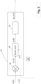
- Fig. 2 schematically illustrates a block diagram of an embodiment of a control unit 22 in accordance with the present invention.
- the Fig. 2 control unit 22 is adapted to control a rotational speed of an output shaft 18 of a propulsion unit 14.
- the control unit 22 is adapted to receive information relating to a speed setpoint value ⁇ s (k), indicative of a rotational speed setpoint for the output shaft 18, and an actual speed value ⁇ (k), indicative of an actual rotational speed of the output shaft 18.
- the parameter k may either be a real number (for instance indicating an actual time instant) or an integer indicating a reference index for a certain time instant such that two adjacent values of the parameter k, such as k-1 and k, indicate adjacent occurrences in time.
- the temporal distance between two adjacent parameter values, such as k-1 and k may be a predetermined time increment.
- the parameter k may be related to certain conditions in an internal combustion engine. Consequently, the temporal distance between two adjacent values of the parameter k may be dependent on the current operating condition of the propulsion unit.
- k is used as an integer.
- the Fig. 2 embodiment of the control unit 22 comprises an acceleration controller 24 adapted to receive the above two values ⁇ s (k), ⁇ (k). Moreover, the control unit 22 is adapted to receive information relating to an acceleration setting member asm. In the Fig. 2 embodiment, the acceleration controller 24 is adapted to receive information relating to an acceleration setting member asm.
- control unit 22 is adapted to determine an acceleration value ⁇ ⁇ s (k) ⁇ using an acceleration value determination procedure comprising employing an acceleration conversion function that uses the speed setpoint value ⁇ s (k), the actual speed value ⁇ (k) and the acceleration setting member asm as inputs and which produces a resulting value ⁇ s (k) to be used for determining the acceleration value acceleration value ⁇ ⁇ s (k) ⁇ .
- the acceleration conversion function is such that different resulting values ⁇ s (k) can be obtained for the same set of the speed setpoint value ⁇ s (k) and the actual speed value ⁇ (k) but for different choices of the acceleration setting member asm.
- the relation between the resulting value ⁇ s (k) and the acceleration value acceleration value ⁇ ⁇ s (k) ⁇ will be presented hereinbelow with reference to Fig. 3 .
- control unit 22 is adapted to determine a torque request value T s (k) using a torque conversion operation that uses the acceleration value ⁇ ⁇ s (k) ⁇ and to issue a signal indicative of the torque request value T s (k) to the propulsion unit 14.
- the Fig. 2 embodiment of the control unit 22 comprises a torque controller 26 adapted to issue the signal indicative of the torque request value T s (k) to the propulsion unit 14 using the acceleration value ⁇ ⁇ s (k) ⁇ .
- FIG. 3 illustrates an example implementation of the acceleration controller 24 introduced in relation to Fig. 2 .
- the Fig. 3 implementation of the acceleration controller 24 comprises a summing point 28, an acceleration converter 30 and an overshoot predictor 32.
- the propulsion assembly - which has been introduced hereinabove and which comprises the propulsion unit 14 and the control unit 22 - may further comprise an acceleration setting arrangement 34 adapted to receive a signal indicative of a selected acceleration setting and in response thereto issue the signal indicative of the acceleration setting member asm to the control unit.
- such an acceleration setting arrangement 34 may comprise a human-machine interface such as a lever, knob, touch screen or the like, via which an operator may select a preferred acceleration setting member asm.
- the acceleration setting arrangement 34 may be adapted so as to automatically set the acceleration setting member asm.
- the acceleration setting member is from a predetermined set of acceleration setting members, the set comprising at least two different acceleration setting members. Preferably the set comprising a continuous range of values for the acceleration setting member.
- the set of acceleration setting members may comprise a limited set of values which may for instance be selected from a look-up table or the like.
- an acceleration converter 30 determines a resulting value ⁇ s (k) from the speed error ⁇ e (k).
- f ⁇ e j , asm ⁇ e k ⁇ asm
- the ⁇ s (k) may be dependent on the square of the acceleration setting member asm or the like.
- the speed error ⁇ e (k) need not be explicitly determined.
- the function f in Eq. 4 hereinabove need not necessarily determine the difference between the speed setpoint value ⁇ s (k) and the actual speed value ⁇ (k).
- the function f in Eq. 4 may refer to a table, such as a look-up table from which resulting values ⁇ s (k) can be looked up and/or interpolated using the speed setpoint value ⁇ s (k), the actual speed value ⁇ (k) and the acceleration setting member asm.
- the acceleration value acceleration value ⁇ ⁇ s (k) ⁇ can be set to equal the resulting value ⁇ s (k).
- the acceleration value determination procedure may further comprise determining an overshoot prediction value for the acceleration value and if the absolute value of the resulting value exceeds the absolute value of the overshoot prediction value, the acceleration value determination procedure sets the acceleration value to equal the overshoot prediction value. Otherwise, the acceleration value determination procedure sets the acceleration value to equal the resulting value.
- the overshoot predictor 32 in Fig. 3 although the feature of determining an overshoot prediction value may be implemented in a plurality of different ways.
- the overshoot prediction value may use values determined for at least one previous time instant for each one of the speed setpoint value ⁇ s (k), the actual speed value ⁇ (k), an actual torque value, indicative of an actual torque of the output shaft 18, a moment of inertia value, a resistive torque value and a torque disturbance value.
- the entities relating to each one of: the actual torque value, the moment of inertia value, the resistive torque value and the torque disturbance value will be presented hereinbelow.
- such a conversion may for instance be performed by the torque controller 26 in Fig. 2 .
- the torque conversion operation may comprise forming a torque request sum by multiplying the acceleration value by a moment of inertia value, indicative of a moment of inertia associated with the propulsion unit, and adding thereto a resistive torque value, indicative of a resistive torque associated with the propulsion unit.
- control unit 22 may be adapted to use the torque request sum as the torque request value.
- T k J ⁇ k ⁇ ⁇ ⁇ ⁇ s k ⁇ + T ⁇ r k
- the torque request sum T(k) may be modified further, e.g. by putting overshoot or undershoot constraints thereon, before forming the torque request value T s ( k) .
- the torque request value T s ( k ) may be set so as to equal the torque request sum T(k).
- the torque conversion operation may further comprise adding a torque disturbance value, indicative of torque disturbance associated with the propulsion unit, to the torque request sum.
- the torque disturbance value T ⁇ d ( k ) may be determined using values determined for at least one previous time instant for each one of an actual torque value T a (k - 1), the moment of inertia value ⁇ ( k - 1), the resistive torque value T ⁇ r (k - 1), the torque disturbance value T ⁇ d (k - 1) and an actual acceleration value ⁇ (k).
- the torque disturbance value T ⁇ d (k - 1) for at least one previous time instant k - 1 may be set to zero when starting the procedure for determining the torque disturbance value T ⁇ d ( k ) .
- the propulsion unit 14 may be connected to a drivetrain 16 for propelling a vehicle 10. Moreover, each one of the moment of inertia value ⁇ ( k ) and resistive torque value T ⁇ r (k) may be determined on the basis on information indicative of at least a current operating condition of the drivetrain 16.
- the torque controller 26 may receive a signal ocs indicative of a current operating condition of the drivetrain 16.
- the signal ocs indicative of the current operating condition of the drivetrain 16 may comprise, or even consist of, information indicative of a current speed ratio, e.g. between the propulsion unit 14 and driving wheels 20 of the vehicle 10 as mentioned hereinabove.
- the moment of inertia value ⁇ ( k ) may be dependent on the current speed ratio.
- each one of the moment of inertia value ⁇ ( k ) and resistive torque value T ⁇ r (k) may be dependent on additional parameters.
- additional parameters may for instance comprise information such as road inclination, viz the inclination of the road on which the vehicle is travelling, vehicle acceleration and wheel speeds.
- the signal ocs indicative of the current operating condition of the drivetrain 16 may comprise information indicative of the conditions of a vehicle that the propulsion unit 14 is propelling.
- the ocs may comprise information indicative of the for instance the actual torque T a (k) being produced by the propulsion unit 14.
- the powertrain 12 may comprise a sensor 23 adapted to determine information indicative of the current operating condition of the propulsion unit 14, such as the current operating condition of the drivetrain 16 and/or the actual torque T a (k).
- a sensor 23 may be adapted to be in communication with one or more portions of the control unit, such as the torque controller 26, such that information determined by the sensor 23 may be forwarded to the relevant portions of the control unit 22.
- propulsion unit 14 for instance be it an internal combustion engine or an electric machine or a combination thereof
- propulsion unit 14 certain implementations for an internal combustion engine will be presented hereinbelow.
- the below examples are presented in relation to a six-cylinder internal combustion engine, such as a six-cylinder diesel engine.
- Fig. 4 illustrates a combustion cycle for three cylinders of a six-cylinder engine.
- Fig. 4 illustrates an injection cycle A, B, C for each one of the three cylinders.
- the injection cycle for each of the other three cylinders of the six-cylinder engine may be synchronized with the three cylinders indicated in Fig. 4 such that each one of the injection cycles A, B, C illustrates the injection cycle for a pair of cylinders of the engine.
- Each cylinder comprises a piston adapted for reciprocal movement in the cylinder between a bottom dead centre and top dead centre.
- the top dead centre TDC for each injection cycle A, B, C is indicated in Fig. 4 .
- a crank angle range of approximately 60° is available for each injection cycle A, B, C during which the torque produced by the stroke of the relevant cylinder can be controlled.
- control of the produced torque may occur between the time instant indicated by k and the time instant indicated by TDC for injection cycle A.
- certain entities used when determining e.g. the torque request sum T(k) may be based on data representing a previous time instants. As has been indicated hereinabove, each time instant k-1, k, k+1 etcetera may be related to a certain crank angle position of the internal combustion engine.
- the torque disturbance value T ⁇ d ( k ) may be determined for a previous time instant for each one of an actual torque value T a (k ⁇ 1), the moment of inertia value ⁇ (k ⁇ 1), the resistive torque value T ⁇ r ( k ⁇ 1), the torque disturbance value T ⁇ d (k - 1) and an actual acceleration value ⁇ (k) .
- ⁇ (k) represents an actual acceleration value at the end of the last injection cycle, starting at k-1 and ending at k.
- the actual acceleration value ⁇ (k) may be determined by determining the rotational speed of the output shaft 18, for instance using the sensor 23 mentioned above, on a plurality of time instants, for instance time instants between k-1 and k, and determining a mean acceleration value by calculating a derivative using the determined rotational speeds as well as information indicative of the time increment between the time instants.
- Eq. 7 contains a term ⁇ that is within the range of zero to one such that 0 ⁇ ⁇ ⁇ 1.
- the term ⁇ can be used for controlling how fast the torque disturbance is learnt by the control unit 22.
- the term ⁇ may improve robustness by avoiding the overcompensation when cylinders are unbalanced and the value of the term ⁇ may for instance be in the range of approximately 0.4.
- the time stamp ⁇ t may be selected so as to be smaller than the time increment between two adjacent time instants, e.g. k ⁇ 1 and k.
- the time stamp ⁇ t may be less than 50%, preferably less than 30%, more preferred less than 10%, of the time increment between two adjacent time instants, e.g. k ⁇ 1 and k.
- the integer m may be set to three.
- ⁇ ( k ⁇ 1) can be expressed as a rotational speed measurement in rpm.
- overshoot prediction value as has been introduced above, may be determined for an internal combustion engine.
- the overshot prediction value determination procedure presented hereinbelow is based on the assumption that the acceleration value to be used when determining the torque request value should not exceed the maximum acceleration that the internal combustion engine could achieve during a predetermined number n of strokes. Furthermore, the maximum achievable acceleration during the predetermined number n of strokes may be based using information from two preceding time instants k-1 and k-2.
- an upper limit ⁇ upper (k) and a lower limit ⁇ lower (k) for the overshoot prediction value ⁇ l ( k ) in the above equations is occasioned by the fact that the overshoot prediction value ⁇ l ( k ), as well as the resulting value ⁇ s (k), may be positive as well as negative.
- Fig. 5 is a flow chart illustrating a method for controlling a rotational speed ⁇ of an output shaft 18 of a propulsion unit 14. The method comprises:
Abstract
- determining a speed setpoint value (ωs(k)), indicative of a rotational speed setpoint for the output shaft (18), and an actual speed value (ω(k)), indicative of an actual rotational speed of the output shaft (18),
- determining an acceleration value (〈ω̇s (k)〉) using an acceleration value determination procedure comprising employing an acceleration conversion function (ƒ(ωs (k), ω(k), asm)) that uses the speed setpoint value (ωs(k)), the actual speed value (ω(k)) and an acceleration setting member (asm) as inputs and which produces a resulting value (ω̇s (k)) to be used for determining the acceleration value (〈ω̇s (k)〉), the acceleration conversion function (f(ωs (k), ω(k), asm) being such that different resulting values (ω̇s (k)) can be obtained for the same set of the speed setpoint value (ωs(k)) and the actual speed value (ω(k)) but for different choices of the acceleration setting member (asm),
- determining a torque request value (Ts (k))using a torque conversion operation that uses the acceleration value (〈ω̇s (k)〉), and
- controlling the propulsion unit (14) using the torque request value.
Description
- The present invention relates to a method for controlling a rotational speed of an output shaft of a propulsion unit. Moreover, the present invention relates to a control unit for controlling a rotational speed of an output shaft of a propulsion unit. Furthermore, the present invention relates to a propulsion assembly. Additionally, the present invention relates to a vehicle.
- The invention can be applied in heavy-duty vehicles, such as trucks, buses and construction equipment. Although the invention will be described with respect to a truck, the invention is not restricted to this particular vehicle, but may also be used in other vehicles such as working machines or seagoing vessels such as boats. Moreover, the present invention may be used in stationary power generators and the like.
- When controlling a rotational speed of an output shaft of a propulsion unit, it is generally desired to ensure that the rotational speed meets a speed setpoint value. Purely by way of example, the speed setpoint value may be set by an operator of the propulsion unit or the speed setpoint value may be set by a control assembly or similar equipment.
- In order to ensure appropriate rotational speed control,
US 7,788 018 B2 discloses a method for controlling an internal combustion engine having a common rail system together with individual accumulators. A rotational speed-control deviation is determined from a target rotational speed that represents the set point for an outer control loop to control the rotational speed, as well as from an actual rotational speed. A target torque is determined from the rotational speed-control deviation via a rotational speed controller as a master controller. - Although the method according to
US 7,788 018 B2 may be useful under certain operating conditions, there may still be a need for further improving the control of a rotational speed of an output shaft of a propulsion unit. - In view of the above, an object of the invention is to enable that a rotational speed of an output shaft of a propulsion unit can be controlled in an appropriate manner.
- According to a first aspect of the invention, the object is achieved by a method according to
claim 1. - As such, the first aspect of the present invention relates to a method for controlling a rotational speed of an output shaft of a propulsion unit. The method comprises:
- determining a speed setpoint value, indicative of a rotational speed setpoint for the output shaft, and an actual speed value, indicative of an actual rotational speed of the output shaft,
- determining an acceleration value using an acceleration value determination procedure comprising employing an acceleration conversion function that uses the speed setpoint value, the actual speed value and an acceleration setting member as inputs and which produces a resulting value to be used for determining the acceleration value, the acceleration conversion function being such that different resulting values can be obtained for the same set of the speed setpoint value and the actual speed value but for different choices of the acceleration setting member,
- determining a torque request value using a torque conversion operation that uses the acceleration value, and
- controlling the propulsion unit using the torque request value.
- The method as recited above implies that different acceleration values may be obtained for different values of the acceleration setting member. This in turn implies that e.g. an operator of a propulsion unit may choose how quickly the actual speed value should approach the speed setpoint value. This will in turn present an operator or a control system with an increased versatility as regards the control of the propulsion unit.
- As used herein, the term "acceleration setting member" relates to an entity that can be used by the acceleration value determination procedure. Purely by way of example, the "acceleration setting member" may be numeric value, such as an integer or a real number. However, it is also contemplated that different choices of the acceleration setting member may be expressed in other terms than numerical. As a non-limiting example, choices for the acceleration setting member may be "low", "medium" or "high"; "A", "B" or "C" or similar.
- Optionally, the torque conversion operation comprises forming a torque request sum by multiplying the acceleration value by a moment of inertia value, indicative of a moment of inertia associated with the propulsion unit, and adding thereto a resistive torque value, indicative of a resistive torque associated with the propulsion unit.
- Forming a torque request sum in accordance with the above implies that an appropriately accurate estimate of the torque request may be arrived at.
- Optionally, the torque conversion operation further comprises adding a torque disturbance value, indicative of torque disturbance associated with the propulsion unit, to the torque request sum.
- The addition of the torque disturbance value implies that the torque request sum, and possibly also the torque request, may include a torque term that is not immediately derivable when studying e.g. the current state of the propulsion unit or the entity, such as a vehicle, powered by the propulsion unit.
- Purely by way of example, the torque disturbance value may be related to one or more of the following:
- a trailer connected to a vehicle hosting the propulsion unit, wherein the trailer may have certain characteristics, such as a number of axles, tires, friction etcetera, which are not known when initiating the method;
- unmodeled disturbances such as power take off equipment, waves/propeller going in/out the water (for a seagoing vessel hosting the propulsion unit);
- a sudden energy consumption change, for instance when the propulsion unit powers a generator;
- uncertainties in measurements: inclination, mass, torque, curvature, etcetera associated with a vehicle propelled by the propulsion unit, and
- uncertainties in parameters: inertia, air drag and rolling resistance coefficients, curvature resistance factor, etcetera associated with a vehicle propelled by the propulsion unit.
- Optionally, the torque disturbance value is determined using values determined for at least one previous time instant for each one of an actual torque value, indicative of an actual torque of the output shaft, the moment of inertia value, the resistive torque value, the torque disturbance value and an actual acceleration value, indicative of an actual acceleration of said output shaft.
- Purely by way of example, each one of the actual torque value and the actual acceleration value can be determined by a sensor associated with the output shaft.
- As may be realized from the above, the torque disturbance value may be determined using inter alia a torque disturbance value for at least one previous time instant. As such, though purely by way of example, the method may comprise setting the torque disturbance value to be a predetermined value, for instance zero, at a certain time instant.
- Purely by way of example, the method may comprise setting the torque disturbance value to be zero when the propulsion unit is started.
- Determining the torque disturbance value using the above values implies an appropriately accurate estimate of the torque disturbance.
- Optionally, the method further comprises using the torque request sum as the torque request value.
- Optionally, the propulsion unit is connected to a drivetrain for propelling a vehicle and each one of the moment of inertia value and resistive torque value is determined on the basis of information indicative of at least a current operating condition of the drivetrain. Such a determination implies that current operating conditions, such as a current speed ratio between the propulsion unit and e.g. ground engaging members such as wheels, are duly accounted for. Purely by way of example, the information indicative of at least a current operating condition of the drivetrain may comprise information indicative of e.g. a road inclination, viz the inclination of the road on which the vehicle is travelling, vehicle acceleration and wheels speeds.
- Optionally, the acceleration setting member, being used by the acceleration conversion function, is from a predetermined set of acceleration setting members, the set comprising at least two different acceleration setting members, preferably the set comprising a continuous range of values for the acceleration setting member. This implies that a user or another system may select an appropriate acceleration setting members and thus arrive at an appropriate resulting value which may be used for arriving at an appropriate acceleration value.
- Optionally, the method comprises selecting an acceleration setting member to be used by the acceleration conversion function.
- Optionally, wherein the acceleration value determination procedure further comprises determining an overshoot prediction value for the acceleration value and if the absolute value of the resulting value exceeds the absolute value of the overshoot prediction value, the acceleration value determination procedure sets the acceleration value to equal the overshoot prediction value, otherwise, the acceleration value determination procedure sets the acceleration value to equal the resulting value.
- The overshoot prediction value implies that the acceleration value may be kept within a reasonable range such that undesirably large acceleration amplitudes are avoided.
- Optionally, the overshoot prediction value is determined using values determined for at least one previous time instant for each one of the speed setpoint value, the actual speed value, an actual torque value, indicative of an actual torque of the output shaft, the moment of inertia value, the resistive torque value and the torque disturbance value.
- According to a second aspect of the invention, the object is achieved by a device according to claim 11.
- As such, the second aspect of the present invention relates to a control unit for controlling a rotational speed of an output shaft of a propulsion unit. The control unit is adapted to:
- receive information relating to a speed setpoint value, indicative of a rotational speed setpoint for the output shaft, and an actual speed value, indicative of an actual rotational speed of the output shaft,
- receive information relating to an acceleration setting member,
- determine an acceleration value using an acceleration value determination procedure comprising employing an acceleration conversion function that uses the speed setpoint value, the actual speed value and the acceleration setting member as inputs and which produces a resulting value to be used for determining the acceleration value, the acceleration conversion function being such that different resulting values can be obtained for the same set of the speed setpoint value and the actual speed value but for different choices of the acceleration setting member,
- determine a torque request value using a torque conversion operation that uses the acceleration value, and
- issue a signal indicative of the torque request value to the propulsion unit.
- Optionally, the torque conversion operation comprises forming a torque request sum by multiplying the acceleration value by a moment of inertia value, indicative of a moment of inertia associated with the propulsion unit, and adding thereto a resistive torque value, indicative of a resistive torque associated with the propulsion unit.
- Optionally, the torque conversion operation further comprises adding a torque disturbance value, indicative of torque disturbance associated with the propulsion unit, to the torque request sum.
- Optionally, the torque disturbance value is determined using values determined for at least one previous time instant for each one of an actual torque value, indicative of an actual torque of the output shaft, the moment of inertia value, the resistive torque value, the torque disturbance value and an actual acceleration value, indicative of an actual acceleration of said output shaft.
- As may be realized from the above, the torque disturbance value may be determined using inter alia a torque disturbance value for at least one previous time instant. As such, though purely by way of example, the method may comprise setting the torque disturbance value to be a predetermined value, for instance zero, at a certain time instant.
- Purely by way of example, the method may comprise setting the torque disturbance value to be zero when the propulsion unit is started.
- Optionally, the control unit is adapted to use the torque request sum as the torque request value.
- Optionally, the propulsion unit is connected to a drivetrain for propelling a vehicle and each one of the moment of inertia value and resistive torque value is determined on the basis on information indicative of at least a current operating condition of the drivetrain.
- Optionally, the acceleration setting member, being used by the acceleration conversion function, is from a predetermined set of acceleration setting members, the set comprising at least two different acceleration setting members, preferably the set comprising a continuous range of values for the acceleration setting member.
- Optionally, the acceleration value determination procedure further comprises determining an overshoot prediction value for the acceleration value and if the absolute value of the resulting value exceeds the absolute value of the overshoot prediction value, the acceleration value determination procedure sets the acceleration value to equal the overshoot prediction value, otherwise, the acceleration value determination procedure sets the acceleration value to equal the resulting value.
- Optionally, the overshoot prediction value is determined using values determined for at least one previous time instant for each one of the speed setpoint value, the actual speed value, an actual torque value, indicative of an actual torque of the output shaft, the moment of inertia value, the resistive torque value and the torque disturbance value.
- A third aspect of the invention relates to a propulsion assembly comprising a propulsion unit and a control unit according to the second aspect of the present invention.
- Optionally, the propulsion assembly further comprises an acceleration setting arrangement adapted to receive a signal indicative of a selected acceleration setting and in response thereto issue the signal indicative of the acceleration setting member to the control unit.
- A fourth aspect of the invention relates to a vehicle comprising a control unit according to the second aspect of the invention or a propulsion assembly according to the third aspect of the present invention.
- Optionally, the vehicle comprises a drivetrain for propelling the vehicle, the propulsion unit being connected to the drivetrain.
- With reference to the appended drawings, below follows a more detailed description of embodiments of the invention cited as examples.
- In the drawings:
-
Fig. 1 is a schematic view of a vehicle; -
Fig. 2 illustrates a block diagram of an embodiment of a control unit in accordance with the present invention; -
Fig. 3 illustrates a block diagram of implementation of a portion of a control unit; -
Fig. 4 schematically illustrates injection cycles for an internal combustion engine, and -
Fig. 5 is a flow chart illustrating an embodiment of the method of the present invention. - The invention will be described below for a vehicle in the form of a
truck 10 such as the truck illustrated inFig. 1 . Thetruck 10 should be seen as an example of a vehicle which could comprise a control unit according to the present invention. - However, the present invention may be implemented in a plurality of different types of vehicles. Purely by way of example, the present invention could be implemented in a truck, a tractor, a car, a bus, a work machine such as a wheel loader or any other type of construction equipment. Moreover, the present invention need not be implanted in a vehicle, but may be used for a stationary propulsion unit, such as a power generator (not shown).
- The
Fig. 1 vehicle comprises apowertrain 12 that in turn comprises apropulsion unit 14 and adrivetrain 16. Purely by way of example, thepropulsion unit 14 may comprise or constitute an internal combustion engine and thedrivetrain 16 may comprise a transmission assembly, such as a gearbox. Moreover, as indicated inFig. 1 , thepropulsion unit 14 comprises anoutput shaft 18. In theFig. 1 embodiment, theoutput shaft 18 is connected to thedrivetrain 16. - Purely by way of example, the
drivetrain 16 may be adapted to assume a plurality of different conditions with different speed ratios between thepropulsion unit 14 and drivingwheels 20 of thevehicle 10. As a non-limiting example, thedrivetrain 16 may comprise a stepped transmission assembly with a fixed set of speed ratios between thepropulsion unit 14 and drivingwheels 20 of thevehicle 10. Alternatively, thedrivetrain 16 may comprise a stepless transmission assembly via which an infinite number set of speed ratios may be obtained between thepropulsion unit 14 and drivingwheels 20 of thevehicle 10. -
Fig. 1 further illustrates that thevehicle 10 may comprise acontrol unit 22 as will be presented further hereinbelow. Thepropulsion unit 14 and thecontrol unit 22 may be regarded as forming part of a propulsion assembly. -
Fig. 2 schematically illustrates a block diagram of an embodiment of acontrol unit 22 in accordance with the present invention. Although details of the present invention will be presented in relation to thecontrol unit 22, it should be noted that the below presentation is equally applicable to other aspects of the present invention. In particular, the below presentation with reference to thecontrol unit 22 is equally applicable to the first aspect of the present invention, viz the method for controlling a rotational speed of anoutput shaft 18 of apropulsion unit 14. - The
Fig. 2 control unit 22 is adapted to control a rotational speed of anoutput shaft 18 of apropulsion unit 14. - The
control unit 22 is adapted to receive information relating to a speed setpoint value ωs(k), indicative of a rotational speed setpoint for theoutput shaft 18, and an actual speed value ω(k), indicative of an actual rotational speed of theoutput shaft 18. Here, the parameter k may either be a real number (for instance indicating an actual time instant) or an integer indicating a reference index for a certain time instant such that two adjacent values of the parameter k, such as k-1 and k, indicate adjacent occurrences in time. Purely by way of example, the temporal distance between two adjacent parameter values, such as k-1 and k, may be a predetermined time increment. As another non-limiting example, an as will be exemplified hereinbelow, the parameter k may be related to certain conditions in an internal combustion engine. Consequently, the temporal distance between two adjacent values of the parameter k may be dependent on the current operating condition of the propulsion unit. In the below description, k is used as an integer. - The
Fig. 2 embodiment of thecontrol unit 22 comprises anacceleration controller 24 adapted to receive the above two values ωs(k), ω(k). Moreover, thecontrol unit 22 is adapted to receive information relating to an acceleration setting member asm. In theFig. 2 embodiment, theacceleration controller 24 is adapted to receive information relating to an acceleration setting member asm. - Furthermore, the
control unit 22 is adapted to determine an acceleration value 〈ω̇s (k)〉 using an acceleration value determination procedure comprising employing an acceleration conversion function that uses the speed setpoint value ωs(k), the actual speed value ω(k) and the acceleration setting member asm as inputs and which produces a resulting value ω̇s (k) to be used for determining the acceleration value acceleration value 〈ω̇s (k)〉. The acceleration conversion function is such that different resulting values ω̇s (k) can be obtained for the same set of the speed setpoint value ωs(k) and the actual speed value ω(k) but for different choices of the acceleration setting member asm. The relation between the resulting value ω̇s (k) and the acceleration value acceleration value 〈ω̇s (k)〉 will be presented hereinbelow with reference toFig. 3 . - Additionally, the
control unit 22 is adapted to determine a torque request value Ts(k) using a torque conversion operation that uses the acceleration value 〈ω̇s (k)〉 and to issue a signal indicative of the torque request value Ts(k) to thepropulsion unit 14. - The
Fig. 2 embodiment of thecontrol unit 22 comprises atorque controller 26 adapted to issue the signal indicative of the torque request value Ts(k) to thepropulsion unit 14 using the acceleration value 〈ω̇s (k)〉. - Non-limiting examples of how the acceleration value acceleration value 〈ω̇S (k)〉 can be determined are presented hereinbelow. As such,
Fig. 3 illustrates an example implementation of theacceleration controller 24 introduced in relation toFig. 2 . TheFig. 3 implementation of theacceleration controller 24 comprises a summingpoint 28, anacceleration converter 30 and anovershoot predictor 32. - Purely by way of example, and as indicated in
Fig. 3 , the propulsion assembly - which has been introduced hereinabove and which comprises thepropulsion unit 14 and the control unit 22 - may further comprise anacceleration setting arrangement 34 adapted to receive a signal indicative of a selected acceleration setting and in response thereto issue the signal indicative of the acceleration setting member asm to the control unit. - As a non-limiting example, such an
acceleration setting arrangement 34 may comprise a human-machine interface such as a lever, knob, touch screen or the like, via which an operator may select a preferred acceleration setting member asm. Alternatively, theacceleration setting arrangement 34 may be adapted so as to automatically set the acceleration setting member asm. - As a non-limiting example, the acceleration setting member is from a predetermined set of acceleration setting members, the set comprising at least two different acceleration setting members. Preferably the set comprising a continuous range of values for the acceleration setting member. As another non-limiting example, the set of acceleration setting members may comprise a limited set of values which may for instance be selected from a look-up table or the like.
- As indicated in
Fig. 3 , the summingpoint 28 calculates the difference between the speed setpoint value ωs(k) and the actual speed value ω(k) and the result of the difference is a speed error ωe(k) as presented hereinbelow:
- Once the speed error ωe(k) has been determined, an
acceleration converter 30 determines a resulting value ω̇s (k) from the speed error ωe(k). Purely by way of example, and as indicated inFig. 3 , theacceleration converter 30 may operate in accordance with the following:
- As a non-limiting example, the acceleration conversion function can be in accordance with the following:

- Moreover, in embodiments of the
control unit 22, the speed error ωe(k) need not be explicitly determined. Instead, the acceleration conversion function can be in accordance with the following example:
- As such, the function f in Eq. 4 hereinabove need not necessarily determine the difference between the speed setpoint value ωs(k) and the actual speed value ω(k). Purely by way of example, the function f in Eq. 4 may refer to a table, such as a look-up table from which resulting values ω̇s (k) can be looked up and/or interpolated using the speed setpoint value ωs(k), the actual speed value ω(k) and the acceleration setting member asm.
- Irrespective of how the resulting value ω̇s (k) is determined, it is used for determining the acceleration value acceleration value 〈ω̇s (k)〉. As a non-limiting example, the acceleration value acceleration value 〈ω̇s (k)〉 can be set to equal the resulting value ω̇s (k).
- However, the acceleration value determination procedure may further comprise determining an overshoot prediction value for the acceleration value and if the absolute value of the resulting value exceeds the absolute value of the overshoot prediction value, the acceleration value determination procedure sets the acceleration value to equal the overshoot prediction value. Otherwise, the acceleration value determination procedure sets the acceleration value to equal the resulting value. The above possibility is exemplified by the
overshoot predictor 32 inFig. 3 although the feature of determining an overshoot prediction value may be implemented in a plurality of different ways. - Irrespective of the implementation of how the overshoot prediction value is determined, the overshoot prediction value may use values determined for at least one previous time instant for each one of the speed setpoint value ωs(k), the actual speed value ω (k), an actual torque value, indicative of an actual torque of the
output shaft 18, a moment of inertia value, a resistive torque value and a torque disturbance value. The entities relating to each one of: the actual torque value, the moment of inertia value, the resistive torque value and the torque disturbance value will be presented hereinbelow. - Turning to the the torque conversion operation, such a conversion may for instance be performed by the
torque controller 26 inFig. 2 . - Purely by way of example, the torque conversion operation may comprise forming a torque request sum by multiplying the acceleration value by a moment of inertia value, indicative of a moment of inertia associated with the propulsion unit, and adding thereto a resistive torque value, indicative of a resistive torque associated with the propulsion unit.
- Preferably, though purely by way of example, the
control unit 22 may be adapted to use the torque request sum as the torque request value. - The forming of the torque request sum in accordance with the above is exemplified hereinbelow.

- T(k) is the torque request sum;
- Ĵ(k) is the moment of inertia value;
- 〈ω̇s 〉 is the acceleration value, and
- T̂r (k) is the resistive torque.
- The torque request sum T(k) may be modified further, e.g. by putting overshoot or undershoot constraints thereon, before forming the torque request value Ts (k). However, it is envisaged that the torque request value T s (k) may be set so as to equal the torque request sum T(k).
- In embodiments of the
control unit 22, the torque conversion operation may further comprise adding a torque disturbance value, indicative of torque disturbance associated with the propulsion unit, to the torque request sum. As such, Eq. 5 may be expanded in accordance with the following:
- T̂d (k) is the torque disturbance value.
- As a non-limiting example, the torque disturbance value T̂d (k) may be determined using values determined for at least one previous time instant for each one of an actual torque value Ta(k - 1), the moment of inertia value Ĵ(k - 1), the resistive torque value T̂r (k - 1), the torque disturbance value T̂d (k - 1) and an actual acceleration value ω̇(k).
- Since a previous value T̂d (k - 1) of the torque disturbance value is used when determining the torque disturbance value T̂d (k), the torque disturbance value T̂d (k - 1) for at least one previous time instant k - 1 may be set to zero when starting the procedure for determining the torque disturbance value T̂d (k). Purely by way of example, the torque disturbance value may be set to zero for k=1 and possibly also for k=2, for instance when starting the
propulsion unit 14. - As has been indicated hereinabove with reference to
Fig. 1 , thepropulsion unit 14 may be connected to adrivetrain 16 for propelling avehicle 10. Moreover, each one of the moment of inertia value Ĵ(k) and resistive torque value T̂r (k) may be determined on the basis on information indicative of at least a current operating condition of thedrivetrain 16. - To this end, though purely by way of example, reference is made to
Fig. 2 again in which it is indicated that thetorque controller 26 may receive a signal ocs indicative of a current operating condition of thedrivetrain 16. As a non-limiting example, the signal ocs indicative of the current operating condition of thedrivetrain 16 may comprise, or even consist of, information indicative of a current speed ratio, e.g. between thepropulsion unit 14 and drivingwheels 20 of thevehicle 10 as mentioned hereinabove. To this end, it should be noted that e.g. the moment of inertia value Ĵ(k) may be dependent on the current speed ratio. - Moreover, it should be noted that each one of the moment of inertia value Ĵ(k) and resistive torque value T̂r (k) may be dependent on additional parameters. As such, in embodiments of the present invention wherein the
control unit 22 is adapted to control a propulsion unit for propelling a vehicle, such additional parameters may for instance comprise information such as road inclination, viz the inclination of the road on which the vehicle is travelling, vehicle acceleration and wheel speeds. As such, the signal ocs indicative of the current operating condition of thedrivetrain 16 may comprise information indicative of the conditions of a vehicle that thepropulsion unit 14 is propelling. - Furthermore, the ocs may comprise information indicative of the for instance the actual torque Ta(k) being produced by the
propulsion unit 14. To this end, though purely by way of example, thepowertrain 12 may comprise asensor 23 adapted to determine information indicative of the current operating condition of thepropulsion unit 14, such as the current operating condition of thedrivetrain 16 and/or the actual torque Ta(k). Purely by way of example, such asensor 23 may be adapted to be in communication with one or more portions of the control unit, such as thetorque controller 26, such that information determined by thesensor 23 may be forwarded to the relevant portions of thecontrol unit 22. - Although the above presentation of the invention is applicable for any type of
propulsion unit 14, for instance be it an internal combustion engine or an electric machine or a combination thereof, certain implementations for an internal combustion engine will be presented hereinbelow. In particular the below examples are presented in relation to a six-cylinder internal combustion engine, such as a six-cylinder diesel engine. -
Fig. 4 illustrates a combustion cycle for three cylinders of a six-cylinder engine. In particular,Fig. 4 illustrates an injection cycle A, B, C for each one of the three cylinders. The injection cycle for each of the other three cylinders of the six-cylinder engine may be synchronized with the three cylinders indicated inFig. 4 such that each one of the injection cycles A, B, C illustrates the injection cycle for a pair of cylinders of the engine. - Each cylinder comprises a piston adapted for reciprocal movement in the cylinder between a bottom dead centre and top dead centre. The top dead centre TDC for each injection cycle A, B, C is indicated in
Fig. 4 . - As may be gleaned from
Fig. 4 , a crank angle range of approximately 60° is available for each injection cycle A, B, C during which the torque produced by the stroke of the relevant cylinder can be controlled. As such, using injection cycle A as an example, control of the produced torque may occur between the time instant indicated by k and the time instant indicated by TDC for injection cycle A. Moreover, as will be elaborated on hereinbelow, certain entities used when determining e.g. the torque request sum T(k) may be based on data representing a previous time instants. As has been indicated hereinabove, each time instant k-1, k, k+1 etcetera may be related to a certain crank angle position of the internal combustion engine. - Purely by way of example, and has been indicated hereinabove, the torque disturbance value T̂d (k) may be determined for a previous time instant for each one of an actual torque value Ta(k ― 1), the moment of inertia value Ĵ(k ― 1), the resistive torque value T̂r (k ― 1), the torque disturbance value T̂d (k - 1) and an actual acceleration value ω̇(k) .
- For an internal combustion engine, in particular with a six-cylinder internal combustion engine, the torque disturbance value T̂d (k) may be determined in accordance with the following:


- Moreover, ω̇(k) represents an actual acceleration value at the end of the last injection cycle, starting at k-1 and ending at k. As a non-limiting example, the actual acceleration value ω̇(k) may be determined by determining the rotational speed of the
output shaft 18, for instance using thesensor 23 mentioned above, on a plurality of time instants, for instance time instants between k-1 and k, and determining a mean acceleration value by calculating a derivative using the determined rotational speeds as well as information indicative of the time increment between the time instants. - It should not be overlooked that Eq. 7 contains a term α that is within the range of zero to one such that 0 ≤ α ≤ 1. The term α can be used for controlling how fast the torque disturbance is learnt by the
control unit 22. Purely by way of example, the term α may improve robustness by avoiding the overcompensation when cylinders are unbalanced and the value of the term α may for instance be in the range of approximately 0.4. - As a non-limiting example, a time dependent variant α'(k) of the term α may be used instead of the term α in Eq. 7, which time dependent variant may be determined in accordance with the following:

- Purely by way of example, for an internal combustion engine with six cylinders operating in pairs, the integer m may be set to three. For the sake of completeness, it should be noted that the term ω(k ― 1) can be expressed as a rotational speed measurement in rpm.
- Presented hereinbelow is an example of how the overshoot prediction value, as has been introduced above, may be determined for an internal combustion engine.
- The overshot prediction value determination procedure presented hereinbelow is based on the assumption that the acceleration value to be used when determining the torque request value should not exceed the maximum acceleration that the internal combustion engine could achieve during a predetermined number n of strokes. Furthermore, the maximum achievable acceleration during the predetermined number n of strokes may be based using information from two preceding time instants k-1 and k-2. To this end, though purely by way of example, an overshoot prediction value ω̇l (k) may be determined in accordance with the following:

- The overshoot prediction value ω̇l (k), as well as the resulting value ω̇s (k) discussed hereinabove, could be used for determining the acceleration value 〈ω̇s (k)〉 in accordance with the following:


- The use of an upper limit ω̇upper (k) and a lower limit ω̇lower (k) for the overshoot prediction value ω̇l (k) in the above equations is occasioned by the fact that the overshoot prediction value ω̇l (k), as well as the resulting value ω̇s (k), may be positive as well as negative.
- It should be noted that the although the above equations Eq. 7 - Eq. 13 have been presented in relation to an internal combustion engine, the equations could also be adapted so as to be applicable for an electric motor.
-
Fig. 5 is a flow chart illustrating a method for controlling a rotational speed ω of anoutput shaft 18 of apropulsion unit 14. The method comprises: - S1. determining a speed setpoint value (ωs(k)), indicative of a rotational speed setpoint for said output shaft (18), and an actual speed value (w(k)), indicative of an actual rotational speed of said output shaft (18),
- S2. determining an acceleration value (〈ω̇s(k)〉) using an acceleration value determination procedure comprising employing an acceleration conversion function (f(ωs (k), ω(k), asm)) that uses said speed setpoint value (ωs(k)), said actual speed value (ω(k)) and an acceleration setting member (asm) as inputs and which produces a resulting value (ω̇s (k)) to be used for determining said acceleration value (〈ω̇ s(k)〉), said acceleration conversion function (f(ωs (k), ω(k), asm) being such that different resulting values (ω̇s (k)) can be obtained for the same set of said speed setpoint value (ωs(k)) and said actual speed value (ω(k)) but for different choices of said acceleration setting member (asm),
- S3. determining a torque request value using a torque conversion operation that uses said acceleration value (〈ω̇ s(k)〉), and
- S4. controlling said propulsion unit (14) using said torque request value.
- It is to be understood that the present invention is not limited to the embodiments described above and illustrated in the drawings; rather, the skilled person will recognize that many changes and modifications may be made within the scope of the appended claims.
Claims (23)
- A method for controlling a rotational speed (ω) of an output shaft (18) of a propulsion unit (14), said method comprising:- determining a speed setpoint value (ωs(k)), indicative of a rotational speed setpoint for said output shaft (18), and an actual speed value (w(k)), indicative of an actual rotational speed of said output shaft (18),- determining an acceleration value (〈ω̇s (k)〉) using an acceleration value determination procedure comprising employing an acceleration conversion function (f(ωs (k), ω(k), asm)) that uses said speed setpoint value (ωs(k)), said actual speed value (ω(k)) and an acceleration setting member (asm) as inputs and which produces a resulting value (ω̇s (k)) to be used for determining said acceleration value (〈ω̇ s(k)〉), said acceleration conversion function (f(ωs(k), ω(k), asm)) being such that different resulting values (ω̇s (k)) can be obtained for the same set of said speed setpoint value (ωs(k)) and said actual speed value (ω(k)) but for different choices of said acceleration setting member (asm),- determining a torque request value (Ts (k)) using a torque conversion operation that uses said acceleration value (〈ω̇ s(k)〉), and- controlling said propulsion unit (14) using said torque request value.
- The method according to claim 1, wherein said torque conversion operation comprises forming a torque request sum (T(k)) by multiplying said acceleration value (〈ω̇s (k)〉) by a moment of inertia value (Ĵ(k)), indicative of a moment of inertia associated with said propulsion unit (14), and adding thereto a resistive torque value (T̂r (k)), indicative of a resistive torque associated with said propulsion unit (14).
- The method according to claim 2, wherein said torque conversion operation further comprises adding a torque disturbance value (T̂d (k)), indicative of torque disturbance associated with said propulsion unit (14), to said torque request sum (T(k)).
- The method according to claim 3, wherein said torque disturbance value (T̂d (k)) is determined using values determined for at least one previous time instant for each one of an actual torque value (Ta(k - 1)), indicative of an actual torque of said output shaft (18), said moment of inertia value (Ĵ(k - 1)), said resistive torque value (T̂r (k - 1)), said torque disturbance value (T̂d (k - 1)) and an actual acceleration value (ω̇(k)), indicative of an actual acceleration of said output shaft (18).
- The method according to any one of claims 2 - 4, further comprising using said torque request sum (T(k)) as said torque request value (Ts (k)).
- The method according to any one of claims 2 - 5, wherein said propulsion unit (14) is connected to a drivetrain for propelling a vehicle (10) and each one of said moment of inertia value (Ĵ(k)) and resistive torque value (T̂r (k)) is determined on the basis on information indicative of at least a current operating condition of said drivetrain.
- The method according to any one of the preceding claims, wherein said acceleration setting member (asm), being used by said acceleration conversion function (f(ωs (k), ω(k), asm)), is from a predetermined set of acceleration setting members (asm), said set comprising at least two different acceleration setting members (asm), preferably said set comprising a continuous range of values for said acceleration setting member (asm).
- The method according to any one of the preceding claims, wherein said method comprises selecting an acceleration setting member (asm) to be used by said acceleration conversion function (f(ωs (k), ω(k),asm)).
- The method according to any one of the preceding claims, wherein said acceleration value determination procedure further comprises determining an overshoot prediction value (ωl (k)) for said acceleration value and if the absolute value of said resulting value (ω̇s (k)) exceeds the absolute value of said overshoot prediction value (ω̇l (k)), said acceleration value determination procedure sets said acceleration value (〈ω̇ s(k)〉) to equal said overshoot prediction value (ω̇l (k)), otherwise, said acceleration value determination procedure sets said acceleration value (〈ω̇ s(k)〉) to equal said resulting value (ω̇s (k)).
- The method according to claim 9, wherein said overshoot prediction value (ω̇l (k)). is determined using values determined for at least one previous time instant for each one of said speed setpoint value (ωs(k-1)), said actual speed value (ω(k-1)), an actual torque value (Ta(k - 1)), indicative of an actual torque of said output shaft (18), said moment of inertia value (Ĵ(k - 2)), said resistive torque value (T̂r(k - 2)) and said torque disturbance value (T̂d(k - 2)).
- A control unit (22) for controlling a rotational speed of an output shaft (18) of a propulsion unit (14), said control unit (22) being adapted to:- receive information relating to a speed setpoint value (ωs(k)), indicative of a rotational speed setpoint for said output shaft (18), and an actual speed value (ω(k)), indicative of an actual rotational speed of said output shaft (18),- receive information relating to an acceleration setting member (asm),- determine an acceleration value (〈ω̇s (k)〉) using an acceleration value determination procedure comprising employing an acceleration conversion function (f(ωs (k), ω(k), asm)) that uses said speed setpoint value (ωs(k)), said actual speed value (ω(k)) and said acceleration setting member (asm) as inputs and which produces a resulting value (ω̇s (k)) to be used for determining said acceleration value (〈ω̇ s(k)〉), said acceleration conversion function (f(ωs (k), ω(k),asm)) being such that different resulting values (ω̇s (k)) can be obtained for the same set of said speed setpoint value (ωs(k)) and said actual speed value (ω(k)) but for different choices of said acceleration setting member (asm),- determine a torque request value (Ts(k)) using a torque conversion operation that uses said acceleration value (〈ω̇ s(k)〉), and- issue a signal indicative of said torque request value to said propulsion unit (14).
- The control unit (22) according to claim 11, wherein said torque conversion operation comprises forming a torque request sum (T(k)) by multiplying said acceleration value (〈ω̇ s(k)〉) by a moment of inertia value (Ĵ(k)), indicative of a moment of inertia associated with said propulsion unit (14), and adding thereto a resistive torque value (T̂r(k)), indicative of a resistive torque associated with said propulsion unit (14).
- The control unit (22) according to claim 12, wherein said torque conversion operation further comprises adding a torque disturbance value (T̂d (k)), indicative of torque disturbance associated with said propulsion unit (14), to said torque request sum (T(k)).
- The control unit (22) according to claim 13, wherein said torque disturbance value (T̂d (k)) is determined using values determined for at least one previous time instant for each one of an actual torque value (Ta(k ― 1)), indicative of an actual torque of said output shaft (18), said moment of inertia value (Ĵ(k - 1)), said resistive torque value (T̂r (k - 1)), said torque disturbance value (T̂d (k - 1)) and an actual acceleration value (ω̇(k)), indicative of an actual acceleration of said output shaft (18).
- The control unit (22) according to any one of claims 12 - 14, wherein said control unit (22) is adapted to use said torque request sum (T(k)) as said torque request value (Ts(k)).
- The control unit (22) according to any one of claims 12 - 15, wherein said propulsion unit (14) is connected to a drivetrain for propelling a vehicle (10) and each one of said moment of inertia value (Ĵ(k)) and resistive torque value (T̂r (k)) is determined on the basis on information indicative of at least a current operating condition of said drivetrain.
- The control unit (22) according to any one of claims 11 - 16, wherein said acceleration setting member (asm), being used by said acceleration conversion function (f(ωs (k), ω(k), asm)), is from a predetermined set of acceleration setting members (asm), said set comprising at least two different acceleration setting members (asm), preferably said set comprising a continuous range of values for said acceleration setting member (asm).
- The control unit (22) according to any one of claims 11 - 17, wherein said acceleration value determination procedure further comprising determining an overshoot prediction value (ωl (k)) for said acceleration value (〈ω̇ s(k)〉) and if the absolute value of said resulting value (ω̇s (k)) exceeds the absolute value of said overshoot prediction value (ω̇l (k)), said acceleration value determination procedure sets said acceleration value (〈ω̇s (k)〉) to equal said overshoot prediction value (ω̇l (k)), otherwise, said acceleration value determination procedure sets said acceleration value (〈ω̇s (k)〉) to equal said resulting value (ω̇s (k)).
- The control unit (22) according to claim 18, wherein said overshoot prediction value (ωl (k)) is determined using values determined for at least one previous time instant for each one of said speed setpoint value (ωs(k-1)), said actual speed value (ω(k-1)), an actual torque value (Ta(k - 1)), indicative of an actual torque of said output shaft (18), said moment of inertia value (Ĵ(k - 2)), said resistive torque value (T̂r (k - 2)) and said torque disturbance value (T̂d (k - 2)).
- A propulsion assembly comprising a propulsion unit (14) and a control unit (22) according to any one of claims 11 - 19.
- The propulsion assembly according to claim 20, wherein said propulsion assembly further comprises an acceleration setting arrangement adapted to receive a signal indicative of a selected acceleration setting and in response thereto issue said signal indicative of said acceleration setting member (asm) to said control unit (22).
- A vehicle (10) comprising a control unit (22) according to any one of claims 11 - 19 or a propulsion assembly according to any one of claims 20 - 21.
- The vehicle (10) according to claim 22, further comprising a drivetrain for propelling said vehicle (10), said propulsion unit (14) being connected to said drivetrain.
Priority Applications (3)
| Application Number | Priority Date | Filing Date | Title |
|---|---|---|---|
| EP21201095.3A EP4163486A1 (en) | 2021-10-06 | 2021-10-06 | A method for controlling a rotational speed of an output shaft of a propulsion unit |
| CN202211197547.6A CN115929487A (en) | 2021-10-06 | 2022-09-29 | Method for controlling the rotational speed of an output shaft of a propulsion unit |
| US17/938,144 US20230105929A1 (en) | 2021-10-06 | 2022-10-05 | Method for controlling a rotational speed of an output shaft of a propulsion unit |
Applications Claiming Priority (1)
| Application Number | Priority Date | Filing Date | Title |
|---|---|---|---|
| EP21201095.3A EP4163486A1 (en) | 2021-10-06 | 2021-10-06 | A method for controlling a rotational speed of an output shaft of a propulsion unit |
Publications (1)
| Publication Number | Publication Date |
|---|---|
| EP4163486A1 true EP4163486A1 (en) | 2023-04-12 |
Family
ID=78085486
Family Applications (1)
| Application Number | Title | Priority Date | Filing Date |
|---|---|---|---|
| EP21201095.3A Pending EP4163486A1 (en) | 2021-10-06 | 2021-10-06 | A method for controlling a rotational speed of an output shaft of a propulsion unit |
Country Status (3)
| Country | Link |
|---|---|
| US (1) | US20230105929A1 (en) |
| EP (1) | EP4163486A1 (en) |
| CN (1) | CN115929487A (en) |
Citations (6)
| Publication number | Priority date | Publication date | Assignee | Title |
|---|---|---|---|---|
| WO2000036475A1 (en) * | 1998-12-15 | 2000-06-22 | Caterpillar Inc. | Acceleration based control system for speed governing |
| US7788018B2 (en) | 2007-08-06 | 2010-08-31 | Mtu Friedrichshafen Gmbh | Method for controlling an internal combustion engine |
| EP2851254A1 (en) * | 2012-05-18 | 2015-03-25 | Yamaha Hatsudoki Kabushiki Kaisha | Vehicle control device and motorcycle provided therewith |
| US20150293543A1 (en) * | 2014-04-10 | 2015-10-15 | Robert Bosch Gmbh | Method for controlling the rotational speed of a motor |
| DE102017005860A1 (en) * | 2016-06-22 | 2017-12-28 | Scania Cv Ab | A method and system for controlling fuel injection in conjunction with an engine starting operation |
| WO2019207542A1 (en) * | 2018-04-27 | 2019-10-31 | Fpt Industrial S.P.A. | Speed control method for an internal combustion engine |
-
2021
- 2021-10-06 EP EP21201095.3A patent/EP4163486A1/en active Pending
-
2022
- 2022-09-29 CN CN202211197547.6A patent/CN115929487A/en active Pending
- 2022-10-05 US US17/938,144 patent/US20230105929A1/en active Pending
Patent Citations (6)
| Publication number | Priority date | Publication date | Assignee | Title |
|---|---|---|---|---|
| WO2000036475A1 (en) * | 1998-12-15 | 2000-06-22 | Caterpillar Inc. | Acceleration based control system for speed governing |
| US7788018B2 (en) | 2007-08-06 | 2010-08-31 | Mtu Friedrichshafen Gmbh | Method for controlling an internal combustion engine |
| EP2851254A1 (en) * | 2012-05-18 | 2015-03-25 | Yamaha Hatsudoki Kabushiki Kaisha | Vehicle control device and motorcycle provided therewith |
| US20150293543A1 (en) * | 2014-04-10 | 2015-10-15 | Robert Bosch Gmbh | Method for controlling the rotational speed of a motor |
| DE102017005860A1 (en) * | 2016-06-22 | 2017-12-28 | Scania Cv Ab | A method and system for controlling fuel injection in conjunction with an engine starting operation |
| WO2019207542A1 (en) * | 2018-04-27 | 2019-10-31 | Fpt Industrial S.P.A. | Speed control method for an internal combustion engine |
Also Published As
| Publication number | Publication date |
|---|---|
| CN115929487A (en) | 2023-04-07 |
| US20230105929A1 (en) | 2023-04-06 |
Similar Documents
| Publication | Publication Date | Title |
|---|---|---|
| US8175790B2 (en) | Engine droop governor and method | |
| US8265849B2 (en) | Drive system for electrically driven dump truck | |
| US10099678B2 (en) | Method of controlling hybrid electric vehicle | |
| US8423218B2 (en) | Travel controller for industrial vehicle | |
| EP2559586A2 (en) | Systems and methods for engine load management for electric drive vehicles | |
| US8249765B2 (en) | Drive system for electrically driven dump truck | |
| US20090132116A1 (en) | Drive system for electrically driven dump truck | |
| CN102069792B (en) | Method for controlling output torque in powertrains | |
| US11351982B2 (en) | Driving force control method and device for hybrid vehicle | |
| WO2012074605A2 (en) | Power source speed control in a machine with a cvt | |
| US11260846B2 (en) | Driving force control method and device for hybrid vehicle | |
| US11312355B2 (en) | Driving force control method and device for hybrid vehicle | |
| US11235749B2 (en) | Driving force control method and device for hybrid vehicle | |
| EP4163486A1 (en) | A method for controlling a rotational speed of an output shaft of a propulsion unit | |
| CN100374699C (en) | Method and device for controlling the drive unit of a vehicle | |
| EP3967542A1 (en) | Method of generating virtual vibration effect of internal combustion engine in electric vehicle | |
| CN107676186A (en) | A kind of engine torque control method | |
| KR101392141B1 (en) | Power control apparatus of hybrid forklift | |
| KR102322388B1 (en) | Apparatus and method for estimating torque of engine clutch in hybrid electric vehicle | |
| GB2571335A (en) | A controller for a vehicle display system | |
| US11066074B2 (en) | Control of an engine of a machine based on detected load requirements of the machine | |
| US11121651B2 (en) | Driving force control method and device for hybrid vehicle | |
| CN110406392B (en) | Off-highway vehicle electric transmission system control method | |
| US11230281B2 (en) | Driving force control method and device for hybrid vehicle | |
| CN101937005B (en) | Method for detecting rated power vehicle speed of diesel vehicle |
Legal Events
| Date | Code | Title | Description |
|---|---|---|---|
| PUAI | Public reference made under article 153(3) epc to a published international application that has entered the european phase |
Free format text: ORIGINAL CODE: 0009012 |
|
| STAA | Information on the status of an ep patent application or granted ep patent |
Free format text: STATUS: THE APPLICATION HAS BEEN PUBLISHED |
|
| AK | Designated contracting states |
Kind code of ref document: A1 Designated state(s): AL AT BE BG CH CY CZ DE DK EE ES FI FR GB GR HR HU IE IS IT LI LT LU LV MC MK MT NL NO PL PT RO RS SE SI SK SM TR |
|
| STAA | Information on the status of an ep patent application or granted ep patent |
Free format text: STATUS: REQUEST FOR EXAMINATION WAS MADE |
|
| 17P | Request for examination filed |
Effective date: 20231011 |
|
| RBV | Designated contracting states (corrected) |
Designated state(s): AL AT BE BG CH CY CZ DE DK EE ES FI FR GB GR HR HU IE IS IT LI LT LU LV MC MK MT NL NO PL PT RO RS SE SI SK SM TR |