EP4163124A1 - Pneumatic tire - Google Patents
Pneumatic tire Download PDFInfo
- Publication number
- EP4163124A1 EP4163124A1 EP21821777.6A EP21821777A EP4163124A1 EP 4163124 A1 EP4163124 A1 EP 4163124A1 EP 21821777 A EP21821777 A EP 21821777A EP 4163124 A1 EP4163124 A1 EP 4163124A1
- Authority
- EP
- European Patent Office
- Prior art keywords
- pneumatic tire
- rubber
- tire
- belt
- mass
- Prior art date
- Legal status (The legal status is an assumption and is not a legal conclusion. Google has not performed a legal analysis and makes no representation as to the accuracy of the status listed.)
- Pending
Links
Images


Classifications
-
- B—PERFORMING OPERATIONS; TRANSPORTING
- B60—VEHICLES IN GENERAL
- B60C—VEHICLE TYRES; TYRE INFLATION; TYRE CHANGING; CONNECTING VALVES TO INFLATABLE ELASTIC BODIES IN GENERAL; DEVICES OR ARRANGEMENTS RELATED TO TYRES
- B60C1/00—Tyres characterised by the chemical composition or the physical arrangement or mixture of the composition
- B60C1/0016—Compositions of the tread
-
- B—PERFORMING OPERATIONS; TRANSPORTING
- B60—VEHICLES IN GENERAL
- B60C—VEHICLE TYRES; TYRE INFLATION; TYRE CHANGING; CONNECTING VALVES TO INFLATABLE ELASTIC BODIES IN GENERAL; DEVICES OR ARRANGEMENTS RELATED TO TYRES
- B60C1/00—Tyres characterised by the chemical composition or the physical arrangement or mixture of the composition
- B60C1/0025—Compositions of the sidewalls
-
- B—PERFORMING OPERATIONS; TRANSPORTING
- B60—VEHICLES IN GENERAL
- B60C—VEHICLE TYRES; TYRE INFLATION; TYRE CHANGING; CONNECTING VALVES TO INFLATABLE ELASTIC BODIES IN GENERAL; DEVICES OR ARRANGEMENTS RELATED TO TYRES
- B60C1/00—Tyres characterised by the chemical composition or the physical arrangement or mixture of the composition
- B60C1/0041—Compositions of the carcass layers
-
- B—PERFORMING OPERATIONS; TRANSPORTING
- B60—VEHICLES IN GENERAL
- B60C—VEHICLE TYRES; TYRE INFLATION; TYRE CHANGING; CONNECTING VALVES TO INFLATABLE ELASTIC BODIES IN GENERAL; DEVICES OR ARRANGEMENTS RELATED TO TYRES
- B60C3/00—Tyres characterised by the transverse section
- B60C3/04—Tyres characterised by the transverse section characterised by the relative dimensions of the section, e.g. low profile
-
- B—PERFORMING OPERATIONS; TRANSPORTING
- B60—VEHICLES IN GENERAL
- B60C—VEHICLE TYRES; TYRE INFLATION; TYRE CHANGING; CONNECTING VALVES TO INFLATABLE ELASTIC BODIES IN GENERAL; DEVICES OR ARRANGEMENTS RELATED TO TYRES
- B60C9/00—Reinforcements or ply arrangement of pneumatic tyres
- B60C9/18—Structure or arrangement of belts or breakers, crown-reinforcing or cushioning layers
- B60C9/20—Structure or arrangement of belts or breakers, crown-reinforcing or cushioning layers built-up from rubberised plies each having all cords arranged substantially parallel
-
- B—PERFORMING OPERATIONS; TRANSPORTING
- B60—VEHICLES IN GENERAL
- B60C—VEHICLE TYRES; TYRE INFLATION; TYRE CHANGING; CONNECTING VALVES TO INFLATABLE ELASTIC BODIES IN GENERAL; DEVICES OR ARRANGEMENTS RELATED TO TYRES
- B60C9/00—Reinforcements or ply arrangement of pneumatic tyres
- B60C9/18—Structure or arrangement of belts or breakers, crown-reinforcing or cushioning layers
- B60C9/20—Structure or arrangement of belts or breakers, crown-reinforcing or cushioning layers built-up from rubberised plies each having all cords arranged substantially parallel
- B60C9/2003—Structure or arrangement of belts or breakers, crown-reinforcing or cushioning layers built-up from rubberised plies each having all cords arranged substantially parallel characterised by the materials of the belt cords
- B60C9/2009—Structure or arrangement of belts or breakers, crown-reinforcing or cushioning layers built-up from rubberised plies each having all cords arranged substantially parallel characterised by the materials of the belt cords comprising plies of different materials
-
- B—PERFORMING OPERATIONS; TRANSPORTING
- B60—VEHICLES IN GENERAL
- B60C—VEHICLE TYRES; TYRE INFLATION; TYRE CHANGING; CONNECTING VALVES TO INFLATABLE ELASTIC BODIES IN GENERAL; DEVICES OR ARRANGEMENTS RELATED TO TYRES
- B60C9/00—Reinforcements or ply arrangement of pneumatic tyres
- B60C9/18—Structure or arrangement of belts or breakers, crown-reinforcing or cushioning layers
- B60C9/20—Structure or arrangement of belts or breakers, crown-reinforcing or cushioning layers built-up from rubberised plies each having all cords arranged substantially parallel
- B60C9/22—Structure or arrangement of belts or breakers, crown-reinforcing or cushioning layers built-up from rubberised plies each having all cords arranged substantially parallel the plies being arranged with all cords disposed along the circumference of the tyre
-
- B—PERFORMING OPERATIONS; TRANSPORTING
- B60—VEHICLES IN GENERAL
- B60C—VEHICLE TYRES; TYRE INFLATION; TYRE CHANGING; CONNECTING VALVES TO INFLATABLE ELASTIC BODIES IN GENERAL; DEVICES OR ARRANGEMENTS RELATED TO TYRES
- B60C9/00—Reinforcements or ply arrangement of pneumatic tyres
- B60C9/18—Structure or arrangement of belts or breakers, crown-reinforcing or cushioning layers
- B60C9/20—Structure or arrangement of belts or breakers, crown-reinforcing or cushioning layers built-up from rubberised plies each having all cords arranged substantially parallel
- B60C9/22—Structure or arrangement of belts or breakers, crown-reinforcing or cushioning layers built-up from rubberised plies each having all cords arranged substantially parallel the plies being arranged with all cords disposed along the circumference of the tyre
- B60C9/2204—Structure or arrangement of belts or breakers, crown-reinforcing or cushioning layers built-up from rubberised plies each having all cords arranged substantially parallel the plies being arranged with all cords disposed along the circumference of the tyre obtained by circumferentially narrow strip winding
-
- B—PERFORMING OPERATIONS; TRANSPORTING
- B60—VEHICLES IN GENERAL
- B60C—VEHICLE TYRES; TYRE INFLATION; TYRE CHANGING; CONNECTING VALVES TO INFLATABLE ELASTIC BODIES IN GENERAL; DEVICES OR ARRANGEMENTS RELATED TO TYRES
- B60C9/00—Reinforcements or ply arrangement of pneumatic tyres
- B60C9/18—Structure or arrangement of belts or breakers, crown-reinforcing or cushioning layers
- B60C9/26—Folded plies
-
- C—CHEMISTRY; METALLURGY
- C08—ORGANIC MACROMOLECULAR COMPOUNDS; THEIR PREPARATION OR CHEMICAL WORKING-UP; COMPOSITIONS BASED THEREON
- C08K—Use of inorganic or non-macromolecular organic substances as compounding ingredients
- C08K3/00—Use of inorganic substances as compounding ingredients
- C08K3/02—Elements
- C08K3/04—Carbon
-
- C—CHEMISTRY; METALLURGY
- C08—ORGANIC MACROMOLECULAR COMPOUNDS; THEIR PREPARATION OR CHEMICAL WORKING-UP; COMPOSITIONS BASED THEREON
- C08K—Use of inorganic or non-macromolecular organic substances as compounding ingredients
- C08K3/00—Use of inorganic substances as compounding ingredients
- C08K3/34—Silicon-containing compounds
- C08K3/36—Silica
-
- C—CHEMISTRY; METALLURGY
- C08—ORGANIC MACROMOLECULAR COMPOUNDS; THEIR PREPARATION OR CHEMICAL WORKING-UP; COMPOSITIONS BASED THEREON
- C08L—COMPOSITIONS OF MACROMOLECULAR COMPOUNDS
- C08L7/00—Compositions of natural rubber
-
- B—PERFORMING OPERATIONS; TRANSPORTING
- B60—VEHICLES IN GENERAL
- B60C—VEHICLE TYRES; TYRE INFLATION; TYRE CHANGING; CONNECTING VALVES TO INFLATABLE ELASTIC BODIES IN GENERAL; DEVICES OR ARRANGEMENTS RELATED TO TYRES
- B60C1/00—Tyres characterised by the chemical composition or the physical arrangement or mixture of the composition
- B60C2001/0066—Compositions of the belt layers
-
- B—PERFORMING OPERATIONS; TRANSPORTING
- B60—VEHICLES IN GENERAL
- B60C—VEHICLE TYRES; TYRE INFLATION; TYRE CHANGING; CONNECTING VALVES TO INFLATABLE ELASTIC BODIES IN GENERAL; DEVICES OR ARRANGEMENTS RELATED TO TYRES
- B60C9/00—Reinforcements or ply arrangement of pneumatic tyres
- B60C9/18—Structure or arrangement of belts or breakers, crown-reinforcing or cushioning layers
- B60C9/20—Structure or arrangement of belts or breakers, crown-reinforcing or cushioning layers built-up from rubberised plies each having all cords arranged substantially parallel
- B60C2009/2035—Structure or arrangement of belts or breakers, crown-reinforcing or cushioning layers built-up from rubberised plies each having all cords arranged substantially parallel built-up by narrow strips
-
- B—PERFORMING OPERATIONS; TRANSPORTING
- B60—VEHICLES IN GENERAL
- B60C—VEHICLE TYRES; TYRE INFLATION; TYRE CHANGING; CONNECTING VALVES TO INFLATABLE ELASTIC BODIES IN GENERAL; DEVICES OR ARRANGEMENTS RELATED TO TYRES
- B60C9/00—Reinforcements or ply arrangement of pneumatic tyres
- B60C9/18—Structure or arrangement of belts or breakers, crown-reinforcing or cushioning layers
- B60C9/20—Structure or arrangement of belts or breakers, crown-reinforcing or cushioning layers built-up from rubberised plies each having all cords arranged substantially parallel
- B60C2009/2074—Physical properties or dimension of the belt cord
- B60C2009/2083—Density in width direction
-
- B—PERFORMING OPERATIONS; TRANSPORTING
- B60—VEHICLES IN GENERAL
- B60C—VEHICLE TYRES; TYRE INFLATION; TYRE CHANGING; CONNECTING VALVES TO INFLATABLE ELASTIC BODIES IN GENERAL; DEVICES OR ARRANGEMENTS RELATED TO TYRES
- B60C9/00—Reinforcements or ply arrangement of pneumatic tyres
- B60C9/18—Structure or arrangement of belts or breakers, crown-reinforcing or cushioning layers
- B60C9/26—Folded plies
- B60C9/263—Folded plies further characterised by an endless zigzag configuration in at least one belt ply, i.e. no cut edge being present
- B60C2009/266—Folded plies further characterised by an endless zigzag configuration in at least one belt ply, i.e. no cut edge being present combined with non folded cut-belt plies
-
- B—PERFORMING OPERATIONS; TRANSPORTING
- B60—VEHICLES IN GENERAL
- B60C—VEHICLE TYRES; TYRE INFLATION; TYRE CHANGING; CONNECTING VALVES TO INFLATABLE ELASTIC BODIES IN GENERAL; DEVICES OR ARRANGEMENTS RELATED TO TYRES
- B60C2200/00—Tyres specially adapted for particular applications
- B60C2200/04—Tyres specially adapted for particular applications for road vehicles, e.g. passenger cars
-
- Y—GENERAL TAGGING OF NEW TECHNOLOGICAL DEVELOPMENTS; GENERAL TAGGING OF CROSS-SECTIONAL TECHNOLOGIES SPANNING OVER SEVERAL SECTIONS OF THE IPC; TECHNICAL SUBJECTS COVERED BY FORMER USPC CROSS-REFERENCE ART COLLECTIONS [XRACs] AND DIGESTS
- Y02—TECHNOLOGIES OR APPLICATIONS FOR MITIGATION OR ADAPTATION AGAINST CLIMATE CHANGE
- Y02T—CLIMATE CHANGE MITIGATION TECHNOLOGIES RELATED TO TRANSPORTATION
- Y02T10/00—Road transport of goods or passengers
- Y02T10/80—Technologies aiming to reduce greenhouse gasses emissions common to all road transportation technologies
- Y02T10/86—Optimisation of rolling resistance, e.g. weight reduction
Definitions
- This disclosure relates to a pneumatic tire.
- Rubber compositions used for producing rubber articles such as tires are generally required to have high durability such as cut resistance.
- Examples of technologies aimed at improving the durability of rubber include the one described in WO/2003/093337 (PTL 1).
- PTL 1 develops a technology that enhances the durability by double network gel, which is a semi-interpenetrating network structure hydrogel or interpenetrating network structure hydrogel obtained by introducing a second monomer component into a network structure formed by polymerizing and cross-linking a first monomer component and polymerizing and optionally cross-linking the second monomer component, where 10 mol% or more of the first monomer component is a charged unsaturated monomer, and 60 mol% or more of the second monomer component is an electrically neutral unsaturated monomer, the amount of the first monomer component: the amount of the second monomer component is in a molar ratio of 1:2 to 1:100, and when polymerizing and cross-linking the second monomer component, the degree of cross-linking is set smaller than when poly
- the pneumatic tire of this disclosure is a pneumatic tire to be mounted on a vehicle, including a tread in contact with a road surface and a belt layer provided inside the tread in the tire radial direction, where
- FIG. 1 is an overall schematic side view of a vehicle equipped with tires. As illustrated in FIG. 1 , the vehicle 1 is a four-wheel vehicle in this embodiment. The vehicle 1 is not limited to a four-wheel vehicle, and it may have a six-wheel configuration or an eight-wheel configuration, for example.
- the vehicle 1 is equipped with a predetermined number of pneumatic tires 10 according to the wheel configuration. Specifically, the pneumatic tires 10 assembled to a rim wheel 100 are mounted on the vehicle 1 at predetermined positions.
- the vehicle 1 is a new small shuttle bus that mainly focuses on transportation of people and goods in the city.
- the new small shuttle bus is assumed to be a vehicle with a total length of 4 m to 7 m, a total width of approximately 2 m, and a gross vehicle weight of approximately 3 tons.
- the size and the gross vehicle weight are not necessarily limited to the above ranges and may deviate from the ranges to some extent.
- the small shuttle bus is not necessarily limited to transportation of people. It may be used for transportation of goods, mobile stores, mobile offices, and the like.
- the small shuttle bus mainly focuses on transportation of people and goods in the city, it is assumed to run at a relatively low running speed (maximum speed of 70 km/h or less, average speed of about 50 km/h). Therefore, measures to prevent hydroplaning may not be emphasized.
- the vehicle 1 is preferably an electric vehicle having an automatic driving function (assuming it is at level four or higher).
- the automatic driving function is not essential, and the vehicle 1 does not have to be an electric vehicle.
- an in-wheel motor (not illustrated in the drawings) as a power unit.
- the entire unit may be provided in the inner space of the rim wheel 100, or part of the unit may be provided in the inner space of the rim wheel 100.
- the vehicle 1 When using an in-wheel motor, the vehicle 1 preferably has an independent steering function that allows each wheel to be steered independently. In this case, the vehicle can turn on the spot and move in the lateral direction, and a power transmission mechanism is unnecessary, which improves the space efficiency of the vehicle 1.
- the vehicle 1 is required to have high space efficiency. Therefore, the pneumatic tire 10 preferably has a diameter as small as possible.
- the vehicle 1 is mounted on the vehicle 1 that has a suitable gross vehicle weight corresponding to the vehicle size and application, so that it is required to have high load capacity (maximum load capacity).
- the pneumatic tire 10 has a load capacity corresponding to the gross vehicle weight of the vehicle 1 while reducing the tire outer diameter OD (not illustrated in FIG. 1 , see FIG. 2 ).
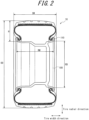
- FIG. 2 is a cross-sectional view of the pneumatic tire 10 and the rim wheel 100. Specifically, FIG. 2 is a cross-sectional view of the pneumatic tire 10 assembled to the rim wheel 100 along the tire width direction and the tire radial direction. Note that in FIG. 2 , the hatching display of the cross section is omitted (the same applies to FIG. 3 and subsequent figures).
- the pneumatic tire 10 has a relatively small diameter but a large width.
- the rim diameter RD which is the diameter of the rim wheel 100, is preferably 12 inches or more and 17.5 inches or less.
- the rim diameter RD may be 10 inches or more and 22 inches or less as long as it satisfies other numerical ranges (formulas 2 and 3 below).
- rim diameter RD is the outer diameter of a rim body portion of the rim wheel 100 and does not include a portion of a rim flange 110, as illustrated in FIG. 2 .
- the tire width SW of the pneumatic tire 10 is preferably 125 mm or more and 255 mm or less. As illustrated in FIG. 2 , the tire width SW means the cross-sectional width of the pneumatic tire 10, and when the pneumatic tire 10 has a rim guard (not illustrated in the drawings), the rim guard portion is not included.
- the aspect ratio of the pneumatic tire 10 is preferably 35 % or more and 75 % or less.
- the aspect ratio is calculated using the following (formula A).
- Aspect ratio % tire section height H/tire width SW section width ⁇ 100
- the tire outer diameter OD which is the outer diameter of the pneumatic tire 10, is 350 mm or more and 600 mm or less.
- the tire outer diameter OD is preferably 500 mm or less.
- the pneumatic tire 10 satisfies the relationships of (formula B) and (formula C). 0.78 ⁇ RW / SW ⁇ 0.88 0.56 ⁇ RD / OD ⁇ 0.66
- the pneumatic tire 10 that satisfies the above relationships can secure the air volume necessary to support the gross vehicle weight of the vehicle 1 while having a small diameter.
- the air volume is preferably 20,000 cm 3 or more in consideration of load supporting performance. Further, it is preferably 80,000 cm 3 or less in consideration of saving space.
- the distance D between bead heels in the tire width direction may be 0.78 ⁇ D / SW ⁇ 0.88 .
- the rim width RW is not particularly limited as long as the above relationship is satisfied. However, from the viewpoint of securing the air volume, the rim width RW is preferably as wide as possible.
- a ratio of the rim diameter RD to the tire outer diameter OD is preferably small, that is, the aspect ratio is preferably high.
- a low aspect ratio is preferable from the viewpoint of responsiveness, and a large rim diameter RD is preferable in consideration of the accommodation space for an in-wheel motor or the like. Therefore, the aspect ratio and the rim diameter RD are in a trade-off relationship between the air volume, and the responsiveness and the accommodation space for an in-wheel motor and the like.
- An example of a suitable size for the pneumatic tire 10 is 215/45R12.
- a suitable rim width is about 7.0 J.
- the set internal pressure (normal internal pressure) of the pneumatic tire 10 is assumed to be 400 kPa to 1,100 kPa and preferably 500 kPa to 900 kPa.
- the normal internal pressure is, for example, the air pressure corresponding to the maximum load capacity in the JATMA (Japan Automobile Tyre Manufacturers Association) YearBook in Japan, ETRTO in Europe, TRA in the United States, and tire standards in other countries.
- the load born by the pneumatic tire 10 is preferably 500 kgf to 1,500 kgf, and it may be about 900 kgf, for example.
- FIG. 3 is a single sectional view of the pneumatic tire 10. Specifically, FIG. 3 is a cross-sectional view of the pneumatic tire 10 along the tire width direction and the tire radial direction.
- the pneumatic tire 10 includes a tread 20, a tire side portion 30, a carcass 40, a belt layer 50, a bead portion 60, and a belt reinforcement layer 70.
- the tread 20 is a portion that contacts a road surface.
- a pattern (not illustrated in the drawings) is formed on the tread 20 according to the service conditions of the pneumatic tire 10 and the type of vehicle on which the pneumatic tire 10 is to be mounted.
- the tread 20 is formed with a plurality of circumferential grooves including a circumferential main groove 21 and a circumferential main groove 22 extending in the tire circumferential direction.
- the tire side portion 30 continues to the tread 20 and is positioned inside the tread 20 in the tire radial direction.
- the tire side portion 30 is an area from the outer end of the tread 20 in the tire width direction to the upper end of the bead portion 60.
- the tire side portion 30 is sometimes called a sidewall or the like.
- the carcass 40 forms the skeleton of the pneumatic tire 10.
- the carcass 40 has a radial structure in which carcass cords (not illustrated in the drawings) radially arranged along the tire radial direction are covered with a rubber material.
- the structure is not limited to a radial structure, and a bias structure in which carcass cords are arranged so as to intersect in the tire radial direction may also be used.
- the belt layer 50 is provided inside the tread 20 in the tire radial direction.
- the belt layer 50 includes a core belt 51 and a sheath belt 52.
- the core belt 51 is provided from one shoulder portion 26 of the tread 20 to the other shoulder portion 27 of the tread 20.
- the shoulder portion 26 is an area outside the circumferential main groove 21 in the tire width direction
- the shoulder portion 27 is an area outside the circumferential main groove 22 in the tire width direction. That is, the shoulder portion 26 and the shoulder portion 27 are areas on the outer side in the tire width direction of the circumferential main grooves that are formed on the outermost side in the tire width direction.
- the core belt 51 is a belt in which belt cords 51a (not illustrated in FIG. 3 , see FIG. 4A ) inclined at a small angle with respect to the tire width direction are covered with rubber.
- the sheath belt 52 is a tape-shaped belt including cords (not illustrated in the drawings) and is wound around the core belt 51 all over the circumference.
- the belt layer 50 serves a similar function as interlaced belt layers. The configuration of the belt layer 50 will be further described later.
- the bead portion 60 continues to the tire side portion 30 and is positioned inside the tire side portion 30 in the tire radial direction.
- the bead portion 60 is engaged with the rim wheel 100 and has an annular bead core 61.
- the carcass 40 is folded outward in the tire width direction via the bead core 61.
- a folded end portion 41 of the carcass 40 folded at the bead portion 60 is provided so as to be wound along the bead core 61.
- the folded end portion 41 is in contact with the outer end of the bead core 61 in the tire radial direction.
- the carcass cord is wound around the outer end of the bead core 61 in the tire radial direction.
- the bead portion 60 may be provided with a bead filler outside the bead core in the tire radial direction, or be provided with a chafer that prevents the carcass 40 and the like folded at the bead portion 60 from rubbing against the rim wheel 100 and being worn.
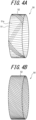
- FIGS. 4A and 4B illustrate the configuration of the belt layer 50. Specifically, FIG. 4A is a single perspective view of the belt layer 50 during production, and FIG. 4B is a single perspective view of the belt layer 50 after production.
- the belt layer 50 includes the core belt 51 and the sheath belt 52. As illustrated in FIG. 4A , the core belt 51 has belt cords 51a arranged along the tire width direction.
- the core belt 51 is an annular belt formed by coating a plurality of belt cords 51a with rubber.
- the belt cord 51a is preferably slightly inclined with respect to the tire width direction, as illustrated in FIG. 4A . Specifically, the belt cord 51a is preferably inclined in the same direction as the inclination direction of the sheath belt 52 (which is upward to the left in FIG. 4A ).
- the sheath belt 52 is a tape-shaped belt with a width of about 1 cm, and it is spirally wound around the core belt 51 along the tire circumferential direction. Specifically, the sheath belt 52 is spirally wound around the core belt 51 along the tire circumferential direction at a predetermined distance equal to or larger than the width of the sheath belt 52.
- the sheath belt 52 is wound a plurality of times in the tire circumferential direction so as not to overlap the adjacent sheath belt 52, so that it covers the outer surface of the core belt 51 in the tire radial direction and the inner surface of the core belt 51 in the tire radial direction.
- the longitudinal ends (not illustrated in the drawings) of the tape-shaped sheath belt 52 are wound around the core belt 51 so as not to be positioned in the shoulder portions 26 and 27 and the central area (immediately below the tire equator line).
- sheath belt 52 is wound around all over the circumference of the annular core belt 51 as illustrated in FIG. 4B .
- the belt layer 50 is composed only of the core belt 51 and the sheath belt 52. As described above, the belt layer 50 serves a similar function as interlaced belt layers.
- one belt reinforcement layer 70 is arranged outside the belt layer 50, which includes the core belt 51 and the sheath belt 52, in the tire radial direction in the illustrated example.
- the belt reinforcement layer 70 may be, for example, one or more layers in which cords extending in the tire circumferential direction are coated with rubber.
- the width of the belt reinforcement layer 70 in the tire width direction is larger than the width of the belt layer 50 in the tire width direction, but it may be equal to or smaller than the width of the belt layer 50 in the tire width direction.
- two or more belt reinforcement layers 70 may be in a so-called cap-and-layer structure, and the belt reinforcement layer on the outer side in the tire radial direction may be provided only on the shoulder portion of each half in the tire width direction.
- the number of the belt cords 51a driven into the core belt 51 is preferably 15 cords/50 mm or more and 30 cords/50 mm or less. Further, the number of the cords driven into the sheath belt 52 is preferably 10 cords/50 mm or more and 25 cords/50 mm or less. Moreover, the number of the driven belt cords 51a is preferably larger than the number of the cords driven into the sheath belt 52 (that is, the former is denser than the latter).
- the angle between the belt cord 51a and the tire width direction is preferably 20 degrees or more and 60 degrees or less.
- the angle between the cord of the sheath belt 52 and the tire width direction is preferably 50 degrees or more and 80 degrees or less. Further, the angle between the cord of the sheath belt 52 and the tire width direction is preferably larger than the angle between the belt cord 51a and the tire width direction.
- the number of turns of the sheath belt 52 in the tire circumferential direction is preferably 3 or more and 6 or less in consideration of ensuring performance and productivity.
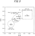
- FIG. 5 is a diagram illustrating typical tire size positioning based on a combination of tire shape (tire outer diameter OD and tire width SW) and rim wheel shape (rim diameter RD and rim width RW).
- the horizontal axis of the graph in FIG. 5 indicates a ratio (RW/SW) of the rim width RW and the tire width SW
- the vertical axis indicates a ratio (RD/OD) of the rim diameter RD and the tire outer diameter OD.
- typical tire size positions are plotted according to RW/SW and RD/OD values.
- both RW/SW and RD/OD are low in the area of tires for trucks and buses. Both RW/SW and RD/OD are higher in the area of tires for passenger vehicles or light trucks than in the area of tires for trucks and buses.
- the area A1 includes 215/45R12, which is an example of a suitable size for the above-described pneumatic tire 10.
- the area A1 is in the ranges of 0.78 ⁇ RW/SW ⁇ 0.88 and 0.56 ⁇ RD/OD ⁇ 0.66 described above.
- Such an area A1 is positioned as an area of tires for new small shuttle buses that mainly focus on transportation of people and goods in the city, such as the vehicle 1 described above.
- the RD/OD in the area of tires for new small shuttle buses is not significantly different from the RD/OD in the area of tires for passenger vehicles or light trucks, and the two areas overlap each other in one part.
- the RW/SW in the area of tires for new small shuttle buses is higher than the RW/SW in the area of tires for passenger vehicles or light trucks.
- the tire outer diameter OD of the pneumatic tire 10 is 350 mm or more and 600 mm or less. Therefore, it has a sufficiently small diameter compared to the size of the vehicle 1 and can contribute to space saving in the vehicle 1.
- the pneumatic tire 10 having a size included in the area A1 satisfies the relationship of 0.78 ⁇ RW / SW ⁇ 0.88 , and therefore the rim width RW is wide with respect to the tire width SW.
- a wide tire can be constructed, and it is easy to secure the air volume necessary for exhibiting high load capacity. If the rim width RW is too wide, the tire width SW also increases, which reduces the space efficiency and makes it easier for the bead portion 60 to come off the rim wheel 100.
- the pneumatic tire 10 having a size included in the area A1 satisfies the relationship of 0.56 ⁇ RD/OD ⁇ 0.66 , and therefore the rim diameter RD is large with respect to the tire outer diameter OD, making it easy to secure accommodation space for an in-wheel motor and the like. If the rim diameter RD is too small, the diameter size of a disc brake or drum brake decreases. As a result, the effective contact area of the brake decreases, making it difficult to secure the required braking performance.
- the rim diameter RD of the pneumatic tire 10 is preferably 12 inches or more and 17.5 inches or less. As a result, a necessary and sufficient air volume and an accommodation space for an in-wheel motor and the like can be secured while maintaining a small diameter. Braking performance and driving performance can also be secured.
- the tire width SW of the pneumatic tire 10 is preferably 125 mm or more and 255 mm or less. Further, the aspect ratio of the pneumatic tire 10 is preferably 35 % or more and 75 % or less. As a result, a necessary and sufficient air volume and an accommodation space for an in-wheel motor and the like can be secured.
- the belt layer 50 includes a core belt 51 provided from one shoulder portion 26 of the tread 20 to the other shoulder portion 27 of the tread 20, and a sheath belt 52 spirally wound around the core belt 51 along the tire circumferential direction, as described above.
- Such a belt layer 50 has high rigidity, particularly at the shoulder portions 26 and 27 of the tread 20, as compared with common interlaced belt layers, and it is possible to effectively suppress the diameter growth of the shoulder portion, which is a concern for small-diameter tires such as the pneumatic tire 10.
- the tire outer diameter OD of the pneumatic tire 10 is small, so that, assuming that the tension of the carcass 40 is constant, the tension of the belt layer 50 is relatively lower than that of a tire having a large tire outer diameter OD. Therefore, the diameter of the tire increases remarkably especially in the shoulder portion where the belt layer has low rigidity.
- the pneumatic tire 10 has a low aspect ratio, so that the pulling force of the carcass 40 is larger in the tire width direction and the pulling force in the tire radial direction is relatively weak. For this reason, the diameter of the tire increases remarkably in the shoulder portion.
- the pneumatic tire 10 should carry a large load and is set to have a high internal pressure corresponding to the gross vehicle weight. Therefore, there is a concern that the durability of the belt layer may deteriorate.
- the belt layer 50 including the core belt 51 and the sheath belt 52 suppresses such diameter growth at the shoulder portions 26 and 27 of the tread 20.
- the durability of the belt (belt layer 50) can be improved while achieving high load capacity and space saving properties.
- the longitudinal ends of the sheath belt 52 that is spirally wound are not positioned in the shoulder portions 26 and 27 (areas on the outer side in the tire width direction of the circumferential main grooves that are formed on the outermost side in the tire radial direction) or the central area (immediately below the tire equator line), which can suppress the occurrence of strain caused by the longitudinal ends of the sheath belt 52.
- the belt cord 51a is inclined in the same direction as the inclination direction of the sheath belt 52.
- the core belt 51 and the sheath belt 52 have similar properties when deformed, which improves the durability of the belt layer 50.
- the sheath belt 52 is a tape-shaped belt, and it is spirally wound around the core belt 51 along the tire circumferential direction at a predetermined distance equal to or larger than the width of the sheath belt 52. Further, the sheath belt 52 is wound a plurality of times in the tire circumferential direction, thereby covering the outer surface of the core belt 51 in the tire radial direction and the inner surface of the core belt 51 in the tire radial direction.
- the belt layer 50 is composed only of the core belt 51 and the sheath belt 52.
- the belt layer 50 including the core belt 51 and the sheath belt 52 can sufficiently suppress the diameter growth in the shoulder portions 26 and 27 of the tread 20, there is no need to further add a reinforcement belt or the like. As a result, the durability of the belt layer 50 can be improved while suppressing the weight increase of the pneumatic tire 10.
- this embodiment uses a rubber composition containing a rubber component containing 50 % by mass or more of natural rubber and/or synthetic isoprene rubber, and syndiotactic 1,2-polybutadiene, where the syndiotactic 1,2-polybutadiene has a crystal content of 7 J/g to 40 J/g and a number average molecular weight of 3.0 ⁇ 10 4 or more.
- sPB syndiotactic 1,2-polybutadiene
- the sPB is a kind of crystalline polymer, and its crystals sacrificially fracture under high strain to dissipate the input energy. Further, the sPB also has the property of being compatible with natural rubber and synthetic isoprene rubber.
- This double network structure provides a high energy dissipation effect due to the sPB crystal part and provides flexibility due to the rubber component/sPB compatible part. Therefore, a pneumatic tire using the rubber composition can achieve excellent wear resistance and cut resistance. Because the rubber composition uses a sPB having high crystallinity and a large molecular weight, crystal collapse does not occur at a low strain input that contributes to rolling resistance. Further, because the molecular weight is larger and the movement of terminal chains is less than that of other general-purpose resins, deterioration of fuel efficiency can also be suppressed.
- a method of confirming whether or not the mesh-like three-dimensional network (double network) structure described above has been formed is not particularly limited.
- the formation of a double network can be confirmed by confirming that the sPB has formed a co-continuous network structure in the matrix polymer of natural rubber and/or isoprene rubber based on a phase image of an atomic force microscope (AFM).
- AFM atomic force microscope
- whether or not the double network has been formed can be inferred from the composition of the rubber composition before vulcanization and production conditions such as vulcanization temperature.
- the rubber composition contains 50 % by mass or more of natural rubber (NR) and/or synthetic isoprene rubber (IR) as a rubber component.
- NR natural rubber
- IR synthetic isoprene rubber
- the rubber component contains 50 % by mass or more of at least one of natural rubber and synthetic isoprene rubber, the above-described sPB double network is formed in the rubber composition after vulcanization. As a result, when it is applied to a tire, the wear resistance and the cut resistance can be improved while maintaining good fuel efficiency.
- the natural rubber (NR) and synthetic isoprene rubber (IR) have isoprene as a monomer and a cis-1,4-polyisoprene structure as a main component.
- the natural rubber may be derived from rubber trees or other plant sources.
- the isoprene monomer for synthesizing the synthetic isoprene rubber may be petroleum-derived or biomass-derived isoprene.
- the content ratio of the natural rubber (NR) and/or synthetic isoprene rubber (IR) is preferably 60 % by mass or more, more preferably 70 % by mass or more, further preferably 80 % by mass or more, particularly preferably 90 % by mass or more, and most preferably 100 % by mass of the rubber component.
- the rubber composition may contain other types of rubber as long as they do not impair the effects of this disclosure.
- the rubber composition also contains syndiotactic 1,2-polybutadiene (sPB) having a crystal content of 7 J/g to 40 J/g and a number average molecular weight of 3.0 ⁇ 10 4 or more.
- sPB syndiotactic 1,2-polybutadiene
- the syndiotactic 1,2-polybutadiene has a crystal content of 7 J/g to 40 J/g. This is because, by setting the crystal content of the sPB to 7 J/g or more, the above-described double network can be more reliably formed in the rubber composition after vulcanization, and the fuel efficiency, wear resistance, and cut resistance can be further improved when applied to a tire. From the same point of view, the crystal content of the sPB is preferably 15 J/g or more and more preferably 17 J/g or more. On the other hand, if the crystal content of the sPB is too large, the melting point of the sPB may become too high, rendering it difficult to set the vulcanization temperature to form the double network.
- the crystal content is set to 40 J/g, preferably 36 J/g or less, and more preferably 31 J/g or less.
- the crystal content of the sPB is the amount of heat of fusion, and it is an index indicating how much the sPB is crystallized. It can be derived from the melting peak measured with a differential scanning calorimeter.
- the syndiotactic 1,2-polybutadiene is required to have a number average molecular weight of 3.0 ⁇ 10 4 or more.
- the number average molecular weight of the sPB may be 5.0 ⁇ 10 4 or more, 6.5 ⁇ 10 4 or more, 8.9 ⁇ 10 4 or more, 10.0 ⁇ 10 4 or more, 11.0 ⁇ 10 4 or more, 12.0 ⁇ 10 4 or more, 13.0 ⁇ 10 4 or more, 14.0 ⁇ 10 4 or more, 15.0 ⁇ 10 4 or more, 16.0 ⁇ 10 4 or more, 17.0 ⁇ 10 4 or more, 17.9 ⁇ 10 4 or more, 18.0 ⁇ 10 4 or more, 19.0 ⁇ 10 4 or more, or 20.0 ⁇ 10 4 or more.
- the sPB preferably has a number average molecular weight of 50.0 ⁇ 10 4 or less.
- the number average molecular weight of the sPB may be 40.0 ⁇ 10 4 or less, 39.0 ⁇ 10 4 or less, 38.0 ⁇ 10 4 or less, 37.0 ⁇ 10 4 or less, 36.0 ⁇ 10 4 or less, 35.0 ⁇ 10 4 or less, 34.7 ⁇ 10 4 or less, 34.0 ⁇ 10 4 or less, 33.0 ⁇ 10 4 or less, 32.0 ⁇ 10 4 or less, 31.0 ⁇ 10 4 or less, or 30.0 ⁇ 10 4 or less.
- the content of 1,2-bond in the sPB (the content of 1,2-bond in the microstructure of the sPB) is preferably 80 % by mass or more and more preferably 85 % by mass or more. This is because in this case, the above-described double network can be more reliably formed in the rubber composition after vulcanization, and the fuel efficiency, wear resistance, and cut resistance when applied to a tire can be further improved.
- the content of 1,2-bond in the sPB may be 90 % by mass or more, 91 % by mass or more, 92 % by mass or more, 93 % by mass or more, 94 % by mass or more, or 95 % by mass or more.
- the content of 1,2-bond in the sPB can be determined by 1 H and 13 C nuclear magnetic resonance (NMR) analysis.
- the syndiotacticity of 1,2-bond of the sPB is preferably 60 % or more and more preferably 65 % or more. This is because in this case, the above-described double network can be more reliably formed in the rubber composition after vulcanization, and the fuel efficiency, wear resistance, and cut resistance when applied to a tire can be further improved. From the same point of view, the syndiotacticity of 1,2-bond of the sPB may be 70 % or more, 75 % or more, 80 % or more, 85 % or more, 90 % or more, 95 % or more, or 100 %.
- the syndiotacticity of 1,2-bond of the sPB can be determined by 1 H and 13 C nuclear magnetic resonance (NMR) analysis.
- the syndiotactic 1,2-polybutadiene may be a copolymer obtained by copolymerizing 1,3-butadiene and a small amount of conjugated diene such as 1,3-pentadiene and 1-pentyl-1,3-butadiene, or it may be a homopolymer of 1,3-butadiene.
- the ratio of a unit derived from 1,3-butadiene in all repeating units of the sPB may be 80 % or more, 85 % or more, 90 % or more, 95 % or more, 98 % or more, or 99 % or more in one embodiment.
- the melting point of the syndiotactic 1,2-polybutadiene is not particularly limited, it is preferably 85 °C to 180 °C from the viewpoint of further improving the wear resistance and cut resistance of the rubber composition.
- the melting point of the sPB may be 170 °C or lower or 160 °C or lower.
- the melting point of the sPB may be 90 °C or higher or 100 °C or higher.
- the content of the syndiotactic 1,2-polybutadiene in the rubber composition is not particularly limited, and it can be appropriately changed according to the required cut resistance and other properties.
- the content of the sPB is preferably 5 parts by mass to 40 parts by mass with respect to 100 parts by mass of the rubber component.
- the content of the sPB may be 10 parts by mass or more or 20 parts by mass or more with respect to 100 parts by mass of the rubber component.
- the content of the sPB is 40 parts by mass or less with respect to 100 parts by mass of the rubber component, deterioration of fuel efficiency can be suppressed.
- a method of obtaining the sPB is not particularly limited, and the sPB may be produced by oneself or may be a commercially available product.
- it can be obtained by polymerizing a 1,3-butadiene monomer in an organic solvent containing an aliphatic solvent using an iron-based catalyst composition, a chromium-based catalyst composition, a cobalt-based catalyst composition, or the like.
- it can be prepared with the polymerization methods described in, for example, JP 2006-063183 A , JP 2000-119324 A , JP 2004-528410 A , JP 2005-518467 A , JP 2005-527641 A , JP 2009-108330 A , JP H07-25212 A , JP H06-306207 A , JP H06-199103 A , JP H06-92108 A , and JP H06-87975 A .
- the iron-based catalyst composition is preferred because it can more reliably control the crystal content of the sPB in the range of 7 J/g to 40 J/g and the number average molecular weight in the range of 3.0 ⁇ 10 4 or more.
- Example of the iron-based catalyst composition include a catalyst composition obtained by mixing (a) an iron-containing compound, (b) an ⁇ -acylphosphonic acid diester and (c) an organoaluminum compound, a catalyst composition obtained by mixing (a) an iron-containing compound, (b) an ⁇ -acylphosphonic acid diester, (c) an organoaluminum compound and other organometallic compounds or a Lewis base, and a catalyst composition including (a) an iron-containing compound, (b) a dihydrocarbyl hydrogen phosphite and (c) an organoaluminum compound.
- the (a) iron-containing compound is not particularly limited, and preferable examples include iron carboxylates, organic iron phosphates, organic iron phosphonates, organic iron phosphinates, iron carbamates, iron dithiocarbamates, iron xanthates, iron ⁇ -diketonates, iron alkoxides or aryloxides, and organic iron compounds.
- the iron-based catalyst composition more preferably contains tris(2-ethylhexanoate) iron (III), bis(2-ethylhexyl) phosphite, triisobutylaluminum, tri-n-butylaluminum, and tri-n-octylaluminum, from the viewpoint of more reliably controlling the crystal content of the sPB in the range of 7 J/g to 40 J/g and the number average molecular weight in the range of 3.0 ⁇ 10 4 or more.
- the chromium-based catalyst composition examples include a three-component catalyst system containing (a) a chromium-containing compound, (b) an alkylaluminum hydride compound, and (c) a hydrogen phosphite.
- Various chromium-containing compounds can be used as the (a) component of the chromium-based catalyst composition according to this disclosure.
- chromium in the (a) chromium-containing compound examples include, but are not limited to, chromium carboxylates, chromium ⁇ -diketonates, chromium alkoxides or aryloxides, chromium halides, pseudo chromium halides, and organochromium compounds.
- cobalt-based catalyst composition examples include a catalyst system containing soluble cobalt, such as cobalt octoate, cobalt 1-naphtate and cobalt benzoate, an organoaluminum compound, such as trimethylaluminum, triethylaluminum, tributylaluminum and triphenylaluminum, and carbon disulfide.
- soluble cobalt such as cobalt octoate, cobalt 1-naphtate and cobalt benzoate
- organoaluminum compound such as trimethylaluminum, triethylaluminum, tributylaluminum and triphenylaluminum
- carbon disulfide examples include carbon disulfide.
- JSR RB ® JSR RB is a registered trademark in Japan, other countries, or both
- JSR RB ® 810, 820, 830, and 840 of JSR Corporation examples of commercial products of the sPB.
- the rubber composition preferably further contains a filler in addition to the rubber component and the syndiotactic 1,2-polybutadiene described above.
- the durability such as the wear resistance and cut resistance of the rubber composition can be further improved.
- the filler is not particularly limited, and examples thereof include carbon black, silica, aluminum hydroxide, clay, alumina, talc, mica, kaolin, glass balloons, glass beads, calcium carbonate, magnesium carbonate, magnesium hydroxide, magnesium oxide, titanium oxide, potassium titanate, and barium sulfate. Among these, it is preferable to contain at least carbon black from the viewpoint of improving the durability. These fillers may be used alone or in combination of two or more. For example, the filler may only contain carbon black.
- the content of the filler is preferably 10 parts by mass to 160 parts by mass, more preferably 15 parts by mass to 140 parts by mass, further preferably 15 parts by mass to 120 parts by mass, and particularly preferably 20 parts by mass to 120 parts by mass with respect to 100 parts by mass of the rubber component.
- the carbon black is not particularly limited, and examples thereof include carbon black of SAF, ISAF, IISAF, N339, HAF, FEF, and GPF grades.
- the nitrogen adsorption specific surface area (N 2 SA, measured according to JIS K 6217-2:2001) of the carbon black is preferably 20 m 2 /g to 160 m 2 /g, more preferably 25 m 2 /g to 160 m 2 /g, still more preferably 25 m 2 /g to 150 m 2 /g, and particularly preferably 30 m 2 /g to 150 m 2 /g.
- the dibutyl phthalate oil absorption (DBP, measured according to JIS K 6217-4: 2008) of the carbon black is preferably 40 ml/100 g to 160 ml/100 g, more preferably 40 ml/100 g to 150 ml/100 g, still more preferably 50 ml/100 g to 150 ml/100 g, even more preferably 60 ml/100 g to 150 ml/100 g, and particularly preferably 60 ml/100 g to 140 ml/100 g.
- the carbon black may be used alone or in combination of two or more.
- the content of the carbon black is preferably 10 parts by mass or more, more preferably 20 parts by mass or more, and particularly preferably 30 parts by mass or more with respect to 100 parts by mass of the rubber component.
- the content of the carbon black is preferably 70 parts by mass or less and more preferably 60 parts by mass or less with respect to 100 parts by mass of the rubber component.
- silica examples include wet silica (hydrous silicic acid), dry silica (anhydrous silicic acid), calcium silicate, and aluminum silicate, among which wet silica is preferable.
- the wet silica preferably has a BET specific surface area (measured according to ISO 5794/1) of 40 m 2 /g to 350 m 2 /g.
- Silica having a BET specific surface area within this range has the advantage of being able to achieve both rubber reinforcing properties and dispersibility in the rubber component. From this point of view, silica having a BET specific surface area in a range of 80 m 2 /g to 300 m 2 /g is more preferable.
- Commercially available products such as "Nipsil AQ" and "Nipsil KQ" manufactured by Tosoh Silica Corporation and "Ultrasil VN3" manufactured by Evonik Industries AG can be used as such silica.
- the silica may be used alone or in combination of two or more.
- the filler may contain carbon black but no silica. In this case, the effect of reducing rolling resistance can be further improved, which is preferable.
- silica When silica is used as the filler, it is preferable to further contain a silane coupling agent, such as bis(3-triethoxysilylpropyl)polysulfide, bis(3-triethoxysilylpropyl)disulfide and 3-trimethoxysilylpropylbenzothiazyltetrasulfide in the rubber composition before vulcanization.
- a silane coupling agent such as bis(3-triethoxysilylpropyl)polysulfide, bis(3-triethoxysilylpropyl)disulfide and 3-trimethoxysilylpropylbenzothiazyltetrasulfide in the rubber composition before vulcanization.
- the content of the silane coupling agent in the rubber composition before vulcanization varies depending on the type of the silane coupling agent and the like, but it is preferably in a range of 2 parts by mass to 20 parts by mass with respect
- the rubber composition may appropriately contain other components commonly used in the rubber industry depending on the required performance.
- the rubber composition before vulcanization may contain a vulcanizing agent (cross-linking agent), a vulcanization accelerator, a vulcanization retarder, an age resistor, a reinforcing agent, a softener, a vulcanizing co-agent, a colorant, a flame retardant, a lubricant, a foaming agent, a plasticizer, a processing aid, an antioxidant, an anti-scorch agent, a ultraviolet rays protecting agent, an antistatic agent, a color protecting agent, oil, and the like, as the other components.
- a vulcanizing agent cross-linking agent
- a vulcanization accelerator cross-linking agent
- a vulcanization retarder an age resistor
- a reinforcing agent e.g., a softener
- a vulcanizing co-agent e.g., a colorant, a flame retardant, a lubricant, a foaming agent, a plastic
- examples of the vulcanizing agent include sulfur (powder sulfur or the like), and sulfur-containing cross-linking agents such as morpholine disulfide and polymer polysulfides.
- examples thereof include peroxide cross-linking such as tert-butyl hydroperoxide, 1,1,3,3-tetramethylbutyl hydroperoxide, cumene hydroperoxide, dicumyl peroxide, di-tert-butyl peroxide, diisopropylbenzene hydroperoxide, and tert-butyl cumyl peroxide.
- vulcanization accelerator examples include a sulfenamide-based vulcanization accelerator, a thiazole-based vulcanization accelerator, a guanidine-based vulcanization accelerator, a thiourea-based vulcanization accelerator, a thiuram-based vulcanization accelerator, a dithiocarbamine-based vulcanization accelerator, and a xanthate-based vulcanization accelerator.
- Examples of a co-crosslinking agent in the peroxide cross-linking include ethylene glycol dimethacrylate, trimethylolpropane trimethacrylate, zinc methacrylate, and magnesium methacrylate.
- a method of preparing the rubber composition before vulcanization is not particularly limited, and a known method can be used. For example, it can be obtained by adding each compounding component simultaneously or in an arbitrary order and kneading them using a kneader such as a Banbury mixer, a roll, or an internal mixer.
- a kneader such as a Banbury mixer, a roll, or an internal mixer.
- the viewpoint of ensuring the formation of the above-described double network in the rubber composition after vulcanization it is possible to use production conditions including a process of kneading each component by setting the temperature at which the syndiotactic 1,2-polybutadiene and the natural rubber and/or synthetic isoprene rubber are kneaded (during kneading in a masterbatch kneading stage) to a temperature 10 °C to 100 °C higher than the melting point of the sPB, and a process of vulcanizing the obtained unvulcanized rubber composition at a temperature equal to or higher than the melting point of the sPB, in preparing the unvulcanized rubber composition.
- production conditions including a process of kneading each component by setting the temperature at which the syndiotactic 1,2-polybutadiene and the natural rubber and/or synthetic isoprene rubber are kneaded (during kneading in
- the sPB becomes semi-compatible with the rubber component and is fixed as a network in the rubber component, thereby forming the above-described double network in the vulcanized rubber composition.
- this does not mean that the double network is not formed at all when the vulcanization is performed at a temperature lower than the melting point of the sPB.
- the double network can be at least partially formed.
- the obtained rubber composition after vulcanization has excellent durability such as cut resistance without deteriorating the low heat generating properties.
- the sPB and the natural rubber and/or synthetic isoprene rubber are kneaded under the above-described production conditions (during kneading in a masterbatch kneading stage), and when the temperature during kneading reaches a temperature 10 °C higher than the melting point of the sPB, it is ensured that the sPB is compatible with the natural rubber and/or the synthetic isoprene rubber.
- the sPB and the natural rubber and/or synthetic isoprene rubber are kneaded under the above-described production conditions (during kneading in a masterbatch kneading stage), and when the temperature during kneading is 100 °C higher than the melting point of the sPB or lower, preferably 50 °C higher than the melting point of the sPB or lower, it is possible to suitably prevent the rubber component and the sPB from thermal aging, which can contribute to improving the cut resistance of the obtained vulcanized rubber composition.
- a kneader such as a Banbury mixer, a roll, an internal mixer, or the like can be used.
- the temperature during kneading in the above-described production conditions refers to the temperature of a masterbatch when a masterbatch of the unvulcanized rubber composition is discharged from the kneading device.
- masterbatch kneading it is the temperature obtained by measuring the internal temperature of the masterbatch immediately after it is discharged from the kneading device, using a temperature sensor or the like.
- the temperature of the masterbatch may be measured when it is discharged.
- the masterbatch is a rubber composition obtained by kneading the rubber component and the sPB in a kneading stage in which no cross-linking agent or vulcanization accelerator is added.
- the vulcanization temperature in the above-described production conditions is preferably a temperature equal to or higher than the melting point of the sPB.
- the reason is as follows. If the vulcanization temperature is equal to or higher than the melting point of the sPB, it is thermodynamically difficult for the sPB in the rubber component to obtain a crystalline domain structure, and the above-described double network can be more reliably formed.
- the temperature during vulcanization in the above-described production conditions means the maximum temperature reached during the vulcanization from the start of vulcanization (usually the set temperature of a vulcanization device).
- a known vulcanization system may be used for the vulcanization in the above-described production method, and it may be a sulfur vulcanization system or a non-sulfur vulcanization system.
- the pneumatic tire of this disclosure uses the above-described rubber composition, there is no particular limitation on the portion to which the rubber composition is applied.
- a tread portion for example, it can be used in at least one of a tread portion, a shoulder portion, a sidewall portion, a bead portion, a belt layer (belt coating rubber) and a carcass (ply coating rubber).
- a belt layer belt coating rubber
- a carcass ply coating rubber
- the pneumatic tire 10 satisfies the relationship 0.56 ⁇ RD/OD ⁇ 0.66, but this relationship does not necessarily have to be satisfied.
- the folded end portion 41 of the carcass 40 is provided so as to be wound along the bead core 61, but the folded end portion 41 does not have to be wound along the bead core 61.
- the sheath belt 52 is spirally wound around the core belt 51 along the tire circumferential direction at a predetermined distance equal to or larger than the width of the sheath belt 52 and covers the outer surface of the core belt 51 in the tire radial direction and the inner surface of the core belt 51 in the tire radial direction, but the sheath belt 52 does not necessarily have to be configured in this way.
- the sheath belt 52 may simply be spirally wound along the tire circumferential direction without leaving a predetermined distance therebetween, and it may not completely cover the outer surface of the core belt 51 in the tire radial direction and the inner surface of the core belt 51 in the tire radial direction.
- the core belt 51 may not necessarily be provided. That is, the sheath belt 52 may simply be spirally wound along the tire circumferential direction without covering the core belt 51.
- the tire of this disclosure can be molded by steam vulcanization or electric vulcanization.
- the syndiotactic 1,2-polybutadiene used in the examples was "JSR RB ® 840" manufactured by JSR Corporation.
- This sPB had a 1,2-bond content of 84 mas%, a melting point of 122 °C, a number average molecular weight of 6.6 ⁇ 10 4 , and a crystal content of 21 J/g.
- the melting point, weight average number average molecular weight (Mw), 1,2-bond content and degree of crystallinity of the sPB were measured with the following methods.
- a sample of the syndiotactic 1,2-polybutadiene was placed in a differential scanning calorimetry (DSC) device, and the melting point was measured with a method in which the melting peak temperature of a DSC curve when the temperature was raised at a heating rate of 10 °C/min was taken as the melting point.
- DSC differential scanning calorimetry
- the crystal content (J/ g) was obtained by calculating the area of the melting peak observed from -100 °C to 200 °C when measuring the melting point, using differential scanning calorimetry (manufactured by TA Instruments).
- a non-productive kneading process (temperature during kneading: 160 °C) was performed with the composition listed in Table 1.
- the components listed in Table 1 were added to a masterbatch obtained from the non-productive kneading process, and a productive vulcanization process (temperature during vulcanization: 150 °C) was performed to obtain a sample of each vulcanized rubber composition.
- a mesh-like three-dimensional network having a portion of sPB crystal and a portion where the rubber component and the sPB were compatible with each other had been formed in the vulcanized rubber in the samples of Examples 1 to 3, based on the presence or absence of the sPB, the melting point of the sPB, and the conditions of the vulcanization temperature.
- compositions in Table 1 are listed in terms of the amount (parts by mass) with respect to 100 parts by mass of the rubber component.
- the tangent loss tan ⁇ of the sample of each vulcanized rubber composition was measured using a viscoelasticity meter (manufactured by Ueshima Seisakusho Co., Ltd.) under conditions of a frequency of 15 Hz, a tensile strain of 2 %, and a temperature of 50 °C.
- the evaluation result is indicated in an index, where the reciprocal of the measured value of tan ⁇ is taken and the index is a value when the reciprocal of Comparative Example 1 is 100. As the index increases, the tan ⁇ decreases, indicating the fuel efficiency improves.
- the tear strength (J/m 2 ) of the sample of each vulcanized rubber composition was measured in a trouser shape according to JIS K 6252 using a tensile tester manufactured by Shimadzu Corporation.
- the index value of Comparative Example 2 is indicated as an index when the tear strength of Comparative Example 1 is 100, and the index value is indicated when the tear strength of Comparative Example 1 is 100. As the index increases, the tear strength increases, indicating the crack growth resistance improves. Table 1 No.
Landscapes
- Engineering & Computer Science (AREA)
- Mechanical Engineering (AREA)
- Chemical & Material Sciences (AREA)
- Health & Medical Sciences (AREA)
- Chemical Kinetics & Catalysis (AREA)
- Medicinal Chemistry (AREA)
- Polymers & Plastics (AREA)
- Organic Chemistry (AREA)
- Tires In General (AREA)
- Compositions Of Macromolecular Compounds (AREA)
Abstract

Description
- This disclosure relates to a pneumatic tire.
- Rubber compositions used for producing rubber articles such as tires are generally required to have high durability such as cut resistance. Examples of technologies aimed at improving the durability of rubber include the one described in
WO/2003/093337 (PTL 1).PTL 1 develops a technology that enhances the durability by double network gel, which is a semi-interpenetrating network structure hydrogel or interpenetrating network structure hydrogel obtained by introducing a second monomer component into a network structure formed by polymerizing and cross-linking a first monomer component and polymerizing and optionally cross-linking the second monomer component, where 10 mol% or more of the first monomer component is a charged unsaturated monomer, and 60 mol% or more of the second monomer component is an electrically neutral unsaturated monomer, the amount of the first monomer component: the amount of the second monomer component is in a molar ratio of 1:2 to 1:100, and when polymerizing and cross-linking the second monomer component, the degree of cross-linking is set smaller than when polymerizing and cross-linking the first monomer component. - In recent years, a new small shuttle bus that mainly focuses on transportation of people and goods in the city has been proposed. Although this shuttle bus is small (approximately 5 meters long and 2 meters wide), it is assumed that the gross vehicle weight may exceed 3 tons. Therefore, pneumatic tires to be mounted on such a vehicle are required to have high load capacity and space-saving properties, and it is desired to develop a technology to achieve the above-described high fuel efficiency as well as rubber strength.
- PTL 1:
WO/2003/093337 - It could thus be helpful to provide a pneumatic tire that has excellent durability and achieves both high load capacity and space-saving properties.
- The pneumatic tire of this disclosure is a pneumatic tire to be mounted on a vehicle, including a tread in contact with a road surface and a belt layer provided inside the tread in the tire radial direction, where
- the pneumatic tire has an outer diameter of 350 mm or more and 600 mm or less, and when the rim width of a rim wheel assembled to the pneumatic tire is defined as RW, and the tire cross-sectional width of the pneumatic tire is defined as SW, they satisfy the relationship of 0.78 ≤ RW/SW ≤ 0.88, and
- the pneumatic tire uses a rubber composition containing a rubber component containing 50 % by mass or more of natural rubber and/or synthetic isoprene rubber, and syndiotactic 1,2-polybutadiene, where the syndiotactic 1,2-polybutadiene has a crystal content of 7 J/g to 40 J/g and a number average molecular weight of 3.0 × 10⁴ or more.
- According to this disclosure, it is possible to provide a pneumatic tire that has excellent durability and achieves both high load capacity and space-saving properties.
- In the accompanying drawings:
-
FIG. 1 is an overall schematic side view of a vehicle equipped with tires; -
FIG. 2 is a cross-sectional view of a pneumatic tire and a rim wheel according to one embodiment of this disclosure; -
FIG. 3 a cross-sectional view in the tire width direction of a pneumatic tire according to one embodiment of this disclosure; -
FIG. 4A is a single perspective view of a belt layer during production; -
FIG. 4B is a single perspective view of a belt layer after production; and -
FIG. 5 is a diagram illustrating typical tire size positioning based on a combination of tire shape (tire outer diameter OD and tire width SW) and rim wheel shape (rim diameter RD and rim width RW) - The following describes the pneumatic tire of this disclosure in detail with reference to the drawings.
-
FIG. 1 is an overall schematic side view of a vehicle equipped with tires. As illustrated inFIG. 1 , thevehicle 1 is a four-wheel vehicle in this embodiment. Thevehicle 1 is not limited to a four-wheel vehicle, and it may have a six-wheel configuration or an eight-wheel configuration, for example. - The
vehicle 1 is equipped with a predetermined number ofpneumatic tires 10 according to the wheel configuration. Specifically, thepneumatic tires 10 assembled to arim wheel 100 are mounted on thevehicle 1 at predetermined positions. - The
vehicle 1 is a new small shuttle bus that mainly focuses on transportation of people and goods in the city. In this embodiment, the new small shuttle bus is assumed to be a vehicle with a total length of 4 m to 7 m, a total width of approximately 2 m, and a gross vehicle weight of approximately 3 tons. However, the size and the gross vehicle weight are not necessarily limited to the above ranges and may deviate from the ranges to some extent. - The small shuttle bus is not necessarily limited to transportation of people. It may be used for transportation of goods, mobile stores, mobile offices, and the like.
- Because the small shuttle bus mainly focuses on transportation of people and goods in the city, it is assumed to run at a relatively low running speed (maximum speed of 70 km/h or less, average speed of about 50 km/h). Therefore, measures to prevent hydroplaning may not be emphasized.
- In this embodiment, the
vehicle 1 is preferably an electric vehicle having an automatic driving function (assuming it is at level four or higher). However, the automatic driving function is not essential, and thevehicle 1 does not have to be an electric vehicle. - When the
vehicle 1 is an electric vehicle, it is preferable to use an in-wheel motor (not illustrated in the drawings) as a power unit. With regard to the in-wheel motor, the entire unit may be provided in the inner space of therim wheel 100, or part of the unit may be provided in the inner space of therim wheel 100. - When using an in-wheel motor, the
vehicle 1 preferably has an independent steering function that allows each wheel to be steered independently. In this case, the vehicle can turn on the spot and move in the lateral direction, and a power transmission mechanism is unnecessary, which improves the space efficiency of thevehicle 1. - As described above, the
vehicle 1 is required to have high space efficiency. Therefore, thepneumatic tire 10 preferably has a diameter as small as possible. - On the other hand, it is mounted on the
vehicle 1 that has a suitable gross vehicle weight corresponding to the vehicle size and application, so that it is required to have high load capacity (maximum load capacity). - Therefore, to meet such requirements, the
pneumatic tire 10 has a load capacity corresponding to the gross vehicle weight of thevehicle 1 while reducing the tire outer diameter OD (not illustrated inFIG. 1 , seeFIG. 2 ). -
FIG. 2 is a cross-sectional view of thepneumatic tire 10 and therim wheel 100. Specifically,FIG. 2 is a cross-sectional view of thepneumatic tire 10 assembled to therim wheel 100 along the tire width direction and the tire radial direction. Note that inFIG. 2 , the hatching display of the cross section is omitted (the same applies toFIG. 3 and subsequent figures). - The
pneumatic tire 10 has a relatively small diameter but a large width. Specifically, the rim diameter RD, which is the diameter of therim wheel 100, is preferably 12 inches or more and 17.5 inches or less. However, the rim diameter RD may be 10 inches or more and 22 inches or less as long as it satisfies other numerical ranges (formulas 2 and 3 below). - Note that the rim diameter RD is the outer diameter of a rim body portion of the
rim wheel 100 and does not include a portion of arim flange 110, as illustrated inFIG. 2 . - The tire width SW of the
pneumatic tire 10 is preferably 125 mm or more and 255 mm or less. As illustrated inFIG. 2 , the tire width SW means the cross-sectional width of thepneumatic tire 10, and when thepneumatic tire 10 has a rim guard (not illustrated in the drawings), the rim guard portion is not included. - The aspect ratio of the
pneumatic tire 10 is preferably 35 % or more and 75 % or less. The aspect ratio is calculated using the following (formula A).
- The tire outer diameter OD, which is the outer diameter of the
pneumatic tire 10, is 350 mm or more and 600 mm or less. The tire outer diameter OD is preferably 500 mm or less. - When the tire outer diameter OD is such a size and the rim width of the
rim wheel 100 assembled to thepneumatic tire 10 is the rim width RW, thepneumatic tire 10 satisfies the relationships of (formula B) and (formula C).

- The
pneumatic tire 10 that satisfies the above relationships can secure the air volume necessary to support the gross vehicle weight of thevehicle 1 while having a small diameter. Specifically, the air volume is preferably 20,000 cm3 or more in consideration of load supporting performance. Further, it is preferably 80,000 cm3 or less in consideration of saving space. - Instead of the RW, the distance D between bead heels in the tire width direction may be

- The rim width RW is not particularly limited as long as the above relationship is satisfied. However, from the viewpoint of securing the air volume, the rim width RW is preferably as wide as possible.
- From the same viewpoint of securing the air volume, a ratio of the rim diameter RD to the tire outer diameter OD is preferably small, that is, the aspect ratio is preferably high. However, as described above, a low aspect ratio is preferable from the viewpoint of responsiveness, and a large rim diameter RD is preferable in consideration of the accommodation space for an in-wheel motor or the like. Therefore, the aspect ratio and the rim diameter RD are in a trade-off relationship between the air volume, and the responsiveness and the accommodation space for an in-wheel motor and the like.
- An example of a suitable size for the
pneumatic tire 10 is 215/45R12. A suitable rim width is about 7.0 J. - Although not particularly limited, the set internal pressure (normal internal pressure) of the
pneumatic tire 10 is assumed to be 400 kPa to 1,100 kPa and preferably 500 kPa to 900 kPa. The normal internal pressure is, for example, the air pressure corresponding to the maximum load capacity in the JATMA (Japan Automobile Tyre Manufacturers Association) YearBook in Japan, ETRTO in Europe, TRA in the United States, and tire standards in other countries. - The load born by the
pneumatic tire 10 is preferably 500 kgf to 1,500 kgf, and it may be about 900 kgf, for example. -
FIG. 3 is a single sectional view of thepneumatic tire 10. Specifically,FIG. 3 is a cross-sectional view of thepneumatic tire 10 along the tire width direction and the tire radial direction. - As illustrated in
FIG. 3 , thepneumatic tire 10 includes atread 20, atire side portion 30, acarcass 40, abelt layer 50, abead portion 60, and abelt reinforcement layer 70. - The
tread 20 is a portion that contacts a road surface. A pattern (not illustrated in the drawings) is formed on thetread 20 according to the service conditions of thepneumatic tire 10 and the type of vehicle on which thepneumatic tire 10 is to be mounted. - In this embodiment, the
tread 20 is formed with a plurality of circumferential grooves including a circumferentialmain groove 21 and a circumferentialmain groove 22 extending in the tire circumferential direction. - The
tire side portion 30 continues to thetread 20 and is positioned inside thetread 20 in the tire radial direction. Thetire side portion 30 is an area from the outer end of thetread 20 in the tire width direction to the upper end of thebead portion 60. Thetire side portion 30 is sometimes called a sidewall or the like. - The
carcass 40 forms the skeleton of thepneumatic tire 10. Thecarcass 40 has a radial structure in which carcass cords (not illustrated in the drawings) radially arranged along the tire radial direction are covered with a rubber material. However, the structure is not limited to a radial structure, and a bias structure in which carcass cords are arranged so as to intersect in the tire radial direction may also be used. - The
belt layer 50 is provided inside thetread 20 in the tire radial direction. Thebelt layer 50 includes acore belt 51 and asheath belt 52. - The
core belt 51 is provided from oneshoulder portion 26 of thetread 20 to theother shoulder portion 27 of thetread 20. Theshoulder portion 26 is an area outside the circumferentialmain groove 21 in the tire width direction, and theshoulder portion 27 is an area outside the circumferentialmain groove 22 in the tire width direction. That is, theshoulder portion 26 and theshoulder portion 27 are areas on the outer side in the tire width direction of the circumferential main grooves that are formed on the outermost side in the tire width direction. - The
core belt 51 is a belt in whichbelt cords 51a (not illustrated inFIG. 3 , seeFIG. 4A ) inclined at a small angle with respect to the tire width direction are covered with rubber. Thesheath belt 52 is a tape-shaped belt including cords (not illustrated in the drawings) and is wound around thecore belt 51 all over the circumference. Thebelt layer 50 serves a similar function as interlaced belt layers. The configuration of thebelt layer 50 will be further described later. - The
bead portion 60 continues to thetire side portion 30 and is positioned inside thetire side portion 30 in the tire radial direction. Thebead portion 60 is engaged with therim wheel 100 and has anannular bead core 61. Thecarcass 40 is folded outward in the tire width direction via thebead core 61. - A folded
end portion 41 of thecarcass 40 folded at thebead portion 60 is provided so as to be wound along thebead core 61. The foldedend portion 41 is in contact with the outer end of thebead core 61 in the tire radial direction. Specifically, at the foldedend portion 41 of thecarcass 40, the carcass cord is wound around the outer end of thebead core 61 in the tire radial direction. - The
bead portion 60 may be provided with a bead filler outside the bead core in the tire radial direction, or be provided with a chafer that prevents thecarcass 40 and the like folded at thebead portion 60 from rubbing against therim wheel 100 and being worn. -
FIGS. 4A and 4B illustrate the configuration of thebelt layer 50. Specifically,FIG. 4A is a single perspective view of thebelt layer 50 during production, andFIG. 4B is a single perspective view of thebelt layer 50 after production. - As described above, the
belt layer 50 includes thecore belt 51 and thesheath belt 52. As illustrated inFIG. 4A , thecore belt 51 hasbelt cords 51a arranged along the tire width direction. Thecore belt 51 is an annular belt formed by coating a plurality ofbelt cords 51a with rubber. - The
belt cord 51a is preferably slightly inclined with respect to the tire width direction, as illustrated inFIG. 4A . Specifically, thebelt cord 51a is preferably inclined in the same direction as the inclination direction of the sheath belt 52 (which is upward to the left inFIG. 4A ). - The
sheath belt 52 is a tape-shaped belt with a width of about 1 cm, and it is spirally wound around thecore belt 51 along the tire circumferential direction. Specifically, thesheath belt 52 is spirally wound around thecore belt 51 along the tire circumferential direction at a predetermined distance equal to or larger than the width of thesheath belt 52. - The
sheath belt 52 is wound a plurality of times in the tire circumferential direction so as not to overlap theadjacent sheath belt 52, so that it covers the outer surface of thecore belt 51 in the tire radial direction and the inner surface of thecore belt 51 in the tire radial direction. - The longitudinal ends (not illustrated in the drawings) of the tape-shaped
sheath belt 52 are wound around thecore belt 51 so as not to be positioned in theshoulder portions - Further, the
sheath belt 52 is wound around all over the circumference of theannular core belt 51 as illustrated inFIG. 4B . - In this embodiment, the
belt layer 50 is composed only of thecore belt 51 and thesheath belt 52. As described above, thebelt layer 50 serves a similar function as interlaced belt layers. In this embodiment, onebelt reinforcement layer 70 is arranged outside thebelt layer 50, which includes thecore belt 51 and thesheath belt 52, in the tire radial direction in the illustrated example. Thebelt reinforcement layer 70 may be, for example, one or more layers in which cords extending in the tire circumferential direction are coated with rubber. In the illustrated example, the width of thebelt reinforcement layer 70 in the tire width direction is larger than the width of thebelt layer 50 in the tire width direction, but it may be equal to or smaller than the width of thebelt layer 50 in the tire width direction. When two or more belt reinforcement layers 70 are provided, they may be in a so-called cap-and-layer structure, and the belt reinforcement layer on the outer side in the tire radial direction may be provided only on the shoulder portion of each half in the tire width direction. - The number of the
belt cords 51a driven into thecore belt 51 is preferably 15 cords/50 mm or more and 30 cords/50 mm or less. Further, the number of the cords driven into thesheath belt 52 is preferably 10 cords/50 mm or more and 25 cords/50 mm or less. Moreover, the number of the drivenbelt cords 51a is preferably larger than the number of the cords driven into the sheath belt 52 (that is, the former is denser than the latter). - The angle between the
belt cord 51a and the tire width direction is preferably 20 degrees or more and 60 degrees or less. The angle between the cord of thesheath belt 52 and the tire width direction is preferably 50 degrees or more and 80 degrees or less. Further, the angle between the cord of thesheath belt 52 and the tire width direction is preferably larger than the angle between thebelt cord 51a and the tire width direction. - The number of turns of the
sheath belt 52 in the tire circumferential direction is preferably 3 or more and 6 or less in consideration of ensuring performance and productivity. - The following describes the functions and effects of the above-described
pneumatic tire 10.FIG. 5 is a diagram illustrating typical tire size positioning based on a combination of tire shape (tire outer diameter OD and tire width SW) and rim wheel shape (rim diameter RD and rim width RW). - Specifically, the horizontal axis of the graph in
FIG. 5 indicates a ratio (RW/SW) of the rim width RW and the tire width SW, and the vertical axis indicates a ratio (RD/OD) of the rim diameter RD and the tire outer diameter OD. InFIG. 5 , typical tire size positions are plotted according to RW/SW and RD/OD values. - As illustrated in
FIG. 5 , both RW/SW and RD/OD are low in the area of tires for trucks and buses. Both RW/SW and RD/OD are higher in the area of tires for passenger vehicles or light trucks than in the area of tires for trucks and buses. - The area A1 includes 215/45R12, which is an example of a suitable size for the above-described
pneumatic tire 10. The area A1 is in the ranges of 0.78 ≤ RW/SW ≤ 0.88 and 0.56 ≤ RD/OD ≤ 0.66 described above. Such an area A1 is positioned as an area of tires for new small shuttle buses that mainly focus on transportation of people and goods in the city, such as thevehicle 1 described above. - The RD/OD in the area of tires for new small shuttle buses is not significantly different from the RD/OD in the area of tires for passenger vehicles or light trucks, and the two areas overlap each other in one part. On the other hand, the RW/SW in the area of tires for new small shuttle buses is higher than the RW/SW in the area of tires for passenger vehicles or light trucks.
- As described above, the tire outer diameter OD of the
pneumatic tire 10 is 350 mm or more and 600 mm or less. Therefore, it has a sufficiently small diameter compared to the size of thevehicle 1 and can contribute to space saving in thevehicle 1. - The
pneumatic tire 10 having a size included in the area A1 satisfies the relationship of
bead portion 60 to come off therim wheel 100. - Further, the
pneumatic tire 10 having a size included in the area A1 satisfies the relationship of
- That is, when the
pneumatic tire 10 is mounted on the new small shuttle bus or the like, it is possible to achieve high space efficiency while providing higher load capacity. - The rim diameter RD of the
pneumatic tire 10 is preferably 12 inches or more and 17.5 inches or less. As a result, a necessary and sufficient air volume and an accommodation space for an in-wheel motor and the like can be secured while maintaining a small diameter. Braking performance and driving performance can also be secured. - The tire width SW of the
pneumatic tire 10 is preferably 125 mm or more and 255 mm or less. Further, the aspect ratio of thepneumatic tire 10 is preferably 35 % or more and 75 % or less. As a result, a necessary and sufficient air volume and an accommodation space for an in-wheel motor and the like can be secured. - In this embodiment, the
belt layer 50 includes acore belt 51 provided from oneshoulder portion 26 of thetread 20 to theother shoulder portion 27 of thetread 20, and asheath belt 52 spirally wound around thecore belt 51 along the tire circumferential direction, as described above. - Such a
belt layer 50 has high rigidity, particularly at theshoulder portions tread 20, as compared with common interlaced belt layers, and it is possible to effectively suppress the diameter growth of the shoulder portion, which is a concern for small-diameter tires such as thepneumatic tire 10. - Specifically, the tire outer diameter OD of the
pneumatic tire 10 is small, so that, assuming that the tension of thecarcass 40 is constant, the tension of thebelt layer 50 is relatively lower than that of a tire having a large tire outer diameter OD. Therefore, the diameter of the tire increases remarkably especially in the shoulder portion where the belt layer has low rigidity. - Further, the
pneumatic tire 10 has a low aspect ratio, so that the pulling force of thecarcass 40 is larger in the tire width direction and the pulling force in the tire radial direction is relatively weak. For this reason, the diameter of the tire increases remarkably in the shoulder portion. - As described above, the
pneumatic tire 10 should carry a large load and is set to have a high internal pressure corresponding to the gross vehicle weight. Therefore, there is a concern that the durability of the belt layer may deteriorate. - In the
pneumatic tire 10, thebelt layer 50 including thecore belt 51 and thesheath belt 52 suppresses such diameter growth at theshoulder portions tread 20. - That is, according to the
pneumatic tire 10, the durability of the belt (belt layer 50) can be improved while achieving high load capacity and space saving properties. - In this embodiment, the longitudinal ends of the
sheath belt 52 that is spirally wound are not positioned in theshoulder portions 26 and 27 (areas on the outer side in the tire width direction of the circumferential main grooves that are formed on the outermost side in the tire radial direction) or the central area (immediately below the tire equator line), which can suppress the occurrence of strain caused by the longitudinal ends of thesheath belt 52. - In this embodiment, the
belt cord 51a is inclined in the same direction as the inclination direction of thesheath belt 52. As a result, thecore belt 51 and thesheath belt 52 have similar properties when deformed, which improves the durability of thebelt layer 50. - In this embodiment, the
sheath belt 52 is a tape-shaped belt, and it is spirally wound around thecore belt 51 along the tire circumferential direction at a predetermined distance equal to or larger than the width of thesheath belt 52. Further, thesheath belt 52 is wound a plurality of times in the tire circumferential direction, thereby covering the outer surface of thecore belt 51 in the tire radial direction and the inner surface of thecore belt 51 in the tire radial direction. - Therefore, it is possible to provide a
belt layer 50 with high rigidity all over the circumference of the tire, particularly at the ends in the tire width direction. As a result, the durability of thebelt layer 50 can be further improved. - In this embodiment, the
belt layer 50 is composed only of thecore belt 51 and thesheath belt 52. As described above, because thebelt layer 50 including thecore belt 51 and thesheath belt 52 can sufficiently suppress the diameter growth in theshoulder portions tread 20, there is no need to further add a reinforcement belt or the like. As a result, the durability of thebelt layer 50 can be improved while suppressing the weight increase of thepneumatic tire 10. - In addition to the above-described structure, this embodiment uses a rubber composition containing a rubber component containing 50 % by mass or more of natural rubber and/or synthetic isoprene rubber, and syndiotactic 1,2-polybutadiene, where the syndiotactic 1,2-polybutadiene has a crystal content of 7 J/g to 40 J/g and a number average molecular weight of 3.0 × 10⁴ or more.
- It is preferable that, after vulcanization, a so-called double network structure, in which syndiotactic 1,2-polybutadiene (hereinafter may be referred to as "sPB") forms a mesh-like three-dimensional network in a rubber component matrix of natural rubber or synthetic isoprene rubber, should be formed in the above-described rubber composition. The sPB is a kind of crystalline polymer, and its crystals sacrificially fracture under high strain to dissipate the input energy. Further, the sPB also has the property of being compatible with natural rubber and synthetic isoprene rubber. Therefore, it is possible to partially immobilize the sPB in the rubber component containing natural rubber and synthetic isoprene rubber, and a three-dimensional network (double network) including a sPB crystal part and a rubber component/sPB compatible part can be formed in the vulcanized rubber.
- This double network structure provides a high energy dissipation effect due to the sPB crystal part and provides flexibility due to the rubber component/sPB compatible part. Therefore, a pneumatic tire using the rubber composition can achieve excellent wear resistance and cut resistance. Because the rubber composition uses a sPB having high crystallinity and a large molecular weight, crystal collapse does not occur at a low strain input that contributes to rolling resistance. Further, because the molecular weight is larger and the movement of terminal chains is less than that of other general-purpose resins, deterioration of fuel efficiency can also be suppressed.
- A method of confirming whether or not the mesh-like three-dimensional network (double network) structure described above has been formed is not particularly limited. For example, the formation of a double network can be confirmed by confirming that the sPB has formed a co-continuous network structure in the matrix polymer of natural rubber and/or isoprene rubber based on a phase image of an atomic force microscope (AFM). Further, whether or not the double network has been formed can be inferred from the composition of the rubber composition before vulcanization and production conditions such as vulcanization temperature.
- The rubber composition contains 50 % by mass or more of natural rubber (NR) and/or synthetic isoprene rubber (IR) as a rubber component. When the rubber component contains 50 % by mass or more of at least one of natural rubber and synthetic isoprene rubber, the above-described sPB double network is formed in the rubber composition after vulcanization. As a result, when it is applied to a tire, the wear resistance and the cut resistance can be improved while maintaining good fuel efficiency.
- The natural rubber (NR) and synthetic isoprene rubber (IR) have isoprene as a monomer and a cis-1,4-polyisoprene structure as a main component. The natural rubber may be derived from rubber trees or other plant sources. The isoprene monomer for synthesizing the synthetic isoprene rubber may be petroleum-derived or biomass-derived isoprene. From the same point of view, the content ratio of the natural rubber (NR) and/or synthetic isoprene rubber (IR) is preferably 60 % by mass or more, more preferably 70 % by mass or more, further preferably 80 % by mass or more, particularly preferably 90 % by mass or more, and most preferably 100 % by mass of the rubber component.
- The rubber composition may contain other types of rubber as long as they do not impair the effects of this disclosure.
- The rubber composition also contains syndiotactic 1,2-polybutadiene (sPB) having a crystal content of 7 J/g to 40 J/g and a number average molecular weight of 3.0 × 10⁴ or more. By containing the sPB together with the natural rubber and/or synthetic isoprene rubber, the above-described double network can be formed in the rubber composition after vulcanization. When it is applied to a tire, the wear resistance and the cut resistance can be improved while maintaining good fuel efficiency.
- The syndiotactic 1,2-polybutadiene has a crystal content of 7 J/g to 40 J/g. This is because, by setting the crystal content of the sPB to 7 J/g or more, the above-described double network can be more reliably formed in the rubber composition after vulcanization, and the fuel efficiency, wear resistance, and cut resistance can be further improved when applied to a tire. From the same point of view, the crystal content of the sPB is preferably 15 J/g or more and more preferably 17 J/g or more. On the other hand, if the crystal content of the sPB is too large, the melting point of the sPB may become too high, rendering it difficult to set the vulcanization temperature to form the double network. In addition, if the crystal content is too large, the fracture elongation of the rubber may tend to decrease due to the crystals acting as fracture nuclei. From this point of view, it is set to 40 J/g, preferably 36 J/g or less, and more preferably 31 J/g or less.
- The crystal content of the sPB is the amount of heat of fusion, and it is an index indicating how much the sPB is crystallized. It can be derived from the melting peak measured with a differential scanning calorimeter.
- From the viewpoint that the above-described double network can be more reliably formed in the rubber composition after vulcanization, and the fuel efficiency, wear resistance, and cut resistance when applied to a tire can be further improved, the syndiotactic 1,2-polybutadiene is required to have a number average molecular weight of 3.0 × 10⁴ or more.
- From the same point of view, the number average molecular weight of the sPB may be 5.0 × 10⁴ or more, 6.5 × 10⁴ or more, 8.9 × 10⁴ or more, 10.0 × 10⁴ or more, 11.0 × 10⁴ or more, 12.0 × 10⁴ or more, 13.0 × 10⁴ or more, 14.0 × 10⁴ or more, 15.0 × 10⁴ or more, 16.0 × 10⁴ or more, 17.0 × 10⁴ or more, 17.9 × 10⁴ or more, 18.0 × 10⁴ or more, 19.0 × 10⁴ or more, or 20.0 × 10⁴ or more. On the other hand, from the viewpoints of crack growth resistance and preventing deterioration of riding comfort when applied to a tire, the sPB preferably has a number average molecular weight of 50.0 × 10⁴ or less. From the same point of view, the number average molecular weight of the sPB may be 40.0 × 10⁴ or less, 39.0 × 10⁴ or less, 38.0 × 10⁴ or less, 37.0 × 10⁴ or less, 36.0 × 10⁴ or less, 35.0 × 10⁴ or less, 34.7 × 10⁴ or less, 34.0 × 10⁴ or less, 33.0 × 10⁴ or less, 32.0 × 10⁴ or less, 31.0 × 10⁴ or less, or 30.0 × 10⁴ or less.
- In the syndiotactic 1,2-polybutadiene, the content of 1,2-bond in the sPB (the content of 1,2-bond in the microstructure of the sPB) is preferably 80 % by mass or more and more preferably 85 % by mass or more. This is because in this case, the above-described double network can be more reliably formed in the rubber composition after vulcanization, and the fuel efficiency, wear resistance, and cut resistance when applied to a tire can be further improved. From the same point of view, the content of 1,2-bond in the sPB may be 90 % by mass or more, 91 % by mass or more, 92 % by mass or more, 93 % by mass or more, 94 % by mass or more, or 95 % by mass or more.
- In this disclosure, the content of 1,2-bond in the sPB can be determined by 1H and 13C nuclear magnetic resonance (NMR) analysis.
- In the syndiotactic 1,2-polybutadiene, the syndiotacticity of 1,2-bond of the sPB is preferably 60 % or more and more preferably 65 % or more. This is because in this case, the above-described double network can be more reliably formed in the rubber composition after vulcanization, and the fuel efficiency, wear resistance, and cut resistance when applied to a tire can be further improved. From the same point of view, the syndiotacticity of 1,2-bond of the sPB may be 70 % or more, 75 % or more, 80 % or more, 85 % or more, 90 % or more, 95 % or more, or 100 %.
- In this disclosure, the syndiotacticity of 1,2-bond of the sPB can be determined by 1H and 13C nuclear magnetic resonance (NMR) analysis.
- The syndiotactic 1,2-polybutadiene may be a copolymer obtained by copolymerizing 1,3-butadiene and a small amount of conjugated diene such as 1,3-pentadiene and 1-pentyl-1,3-butadiene, or it may be a homopolymer of 1,3-butadiene.
- When the sPB contains a unit derived from a conjugated diene other than 1,3-butadiene, the ratio of a unit derived from 1,3-butadiene in all repeating units of the sPB may be 80 % or more, 85 % or more, 90 % or more, 95 % or more, 98 % or more, or 99 % or more in one embodiment.
- Although the melting point of the syndiotactic 1,2-polybutadiene is not particularly limited, it is preferably 85 °C to 180 °C from the viewpoint of further improving the wear resistance and cut resistance of the rubber composition. By setting the melting point of the sPB to 180 °C or lower, the crystallization of the sPB is facilitated during vulcanization of the rubber composition, and the above-described double network can be more reliably formed in the rubber composition after vulcanization. From the same point of view, the melting point of the sPB may be 170 °C or lower or 160 °C or lower. On the other hand, by setting the melting point of the sPB to 85 °C or higher, it is possible to suppress deterioration in the heat resistance and strength of the vulcanized rubber. From the same point of view, the melting point of the sPB may be 90 °C or higher or 100 °C or higher.
- The content of the syndiotactic 1,2-polybutadiene in the rubber composition is not particularly limited, and it can be appropriately changed according to the required cut resistance and other properties. For example, from the viewpoint of further improving the fuel efficiency, wear resistance, and cut resistance of the tire, the content of the sPB is preferably 5 parts by mass to 40 parts by mass with respect to 100 parts by mass of the rubber component. When the content of the sPB is 5 parts by mass or more with respect to 100 parts by mass of the rubber component, the energy dissipation effect is enhanced, thereby obtaining better wear resistance and cut resistance. From the same point of view, the content of the sPB may be 10 parts by mass or more or 20 parts by mass or more with respect to 100 parts by mass of the rubber component. On the other hand, when the content of the sPB is 40 parts by mass or less with respect to 100 parts by mass of the rubber component, deterioration of fuel efficiency can be suppressed.
- A method of obtaining the sPB is not particularly limited, and the sPB may be produced by oneself or may be a commercially available product.
- For example, it can be obtained by polymerizing a 1,3-butadiene monomer in an organic solvent containing an aliphatic solvent using an iron-based catalyst composition, a chromium-based catalyst composition, a cobalt-based catalyst composition, or the like. Specifically, it can be prepared with the polymerization methods described in, for example,
JP 2006-063183 A JP 2000-119324 A JP 2004-528410 A JP 2005-518467 A JP 2005-527641 A JP 2009-108330 A JP H07-25212 A JP H06-306207 A JP H06-199103 A JP H06-92108 A JP H06-87975 A - Among these catalyst compositions, the iron-based catalyst composition is preferred because it can more reliably control the crystal content of the sPB in the range of 7 J/g to 40 J/g and the number average molecular weight in the range of 3.0 × 10⁴ or more.
- Example of the iron-based catalyst composition include a catalyst composition obtained by mixing (a) an iron-containing compound, (b) an α-acylphosphonic acid diester and (c) an organoaluminum compound, a catalyst composition obtained by mixing (a) an iron-containing compound, (b) an α-acylphosphonic acid diester, (c) an organoaluminum compound and other organometallic compounds or a Lewis base, and a catalyst composition including (a) an iron-containing compound, (b) a dihydrocarbyl hydrogen phosphite and (c) an organoaluminum compound.
- The (a) iron-containing compound is not particularly limited, and preferable examples include iron carboxylates, organic iron phosphates, organic iron phosphonates, organic iron phosphinates, iron carbamates, iron dithiocarbamates, iron xanthates, iron α-diketonates, iron alkoxides or aryloxides, and organic iron compounds.
- Among these compounds, the iron-based catalyst composition more preferably contains tris(2-ethylhexanoate) iron (III), bis(2-ethylhexyl) phosphite, triisobutylaluminum, tri-n-butylaluminum, and tri-n-octylaluminum, from the viewpoint of more reliably controlling the crystal content of the sPB in the range of 7 J/g to 40 J/g and the number average molecular weight in the range of 3.0 × 10⁴ or more.
- Examples of the chromium-based catalyst composition include a three-component catalyst system containing (a) a chromium-containing compound, (b) an alkylaluminum hydride compound, and (c) a hydrogen phosphite. Various chromium-containing compounds can be used as the (a) component of the chromium-based catalyst composition according to this disclosure. In general, it is advantageous to use a chromium-containing compound that is soluble in hydrocarbon solvents, such as aromatic, aliphatic or alicyclic hydrocarbons, but it is also acceptable that an insoluble chromium-containing compound that is simply dispersed in a polymerization medium produces a catalytically active species. Therefore, no limitations should be placed on the chromium-containing compound to ensure solubility.
- Examples of chromium in the (a) chromium-containing compound include, but are not limited to, chromium carboxylates, chromium β-diketonates, chromium alkoxides or aryloxides, chromium halides, pseudo chromium halides, and organochromium compounds.
- Examples of the cobalt-based catalyst composition include a catalyst system containing soluble cobalt, such as cobalt octoate, cobalt 1-naphtate and cobalt benzoate, an organoaluminum compound, such as trimethylaluminum, triethylaluminum, tributylaluminum and triphenylaluminum, and carbon disulfide.
- Examples of commercial products of the sPB include JSR RB® (JSR RB is a registered trademark in Japan, other countries, or both) series such as JSR RB® 810, 820, 830, and 840 of JSR Corporation.
- The rubber composition preferably further contains a filler in addition to the rubber component and the syndiotactic 1,2-polybutadiene described above.
- By containing the filler, the durability such as the wear resistance and cut resistance of the rubber composition can be further improved.
- The filler is not particularly limited, and examples thereof include carbon black, silica, aluminum hydroxide, clay, alumina, talc, mica, kaolin, glass balloons, glass beads, calcium carbonate, magnesium carbonate, magnesium hydroxide, magnesium oxide, titanium oxide, potassium titanate, and barium sulfate. Among these, it is preferable to contain at least carbon black from the viewpoint of improving the durability. These fillers may be used alone or in combination of two or more. For example, the filler may only contain carbon black.
- For example, the content of the filler is preferably 10 parts by mass to 160 parts by mass, more preferably 15 parts by mass to 140 parts by mass, further preferably 15 parts by mass to 120 parts by mass, and particularly preferably 20 parts by mass to 120 parts by mass with respect to 100 parts by mass of the rubber component.
- The carbon black is not particularly limited, and examples thereof include carbon black of SAF, ISAF, IISAF, N339, HAF, FEF, and GPF grades. The nitrogen adsorption specific surface area (N2SA, measured according to JIS K 6217-2:2001) of the carbon black is preferably 20 m2/g to 160 m2/g, more preferably 25 m2/g to 160 m2/g, still more preferably 25 m2/g to 150 m2/g, and particularly preferably 30 m2/g to 150 m2/g. The dibutyl phthalate oil absorption (DBP, measured according to JIS K 6217-4: 2008) of the carbon black is preferably 40 ml/100 g to 160 ml/100 g, more preferably 40 ml/100 g to 150 ml/100 g, still more preferably 50 ml/100 g to 150 ml/100 g, even more preferably 60 ml/100 g to 150 ml/100 g, and particularly preferably 60 ml/100 g to 140 ml/100 g. The carbon black may be used alone or in combination of two or more.
- From the viewpoint of further increasing the durability of the rubber composition, the content of the carbon black is preferably 10 parts by mass or more, more preferably 20 parts by mass or more, and particularly preferably 30 parts by mass or more with respect to 100 parts by mass of the rubber component. On the other hand, from the viewpoint of suppressing deterioration of the low-loss properties of the rubber composition and deterioration of the fuel efficiency of the pneumatic tire, the content of the carbon black is preferably 70 parts by mass or less and more preferably 60 parts by mass or less with respect to 100 parts by mass of the rubber component.
- Examples of the silica include wet silica (hydrous silicic acid), dry silica (anhydrous silicic acid), calcium silicate, and aluminum silicate, among which wet silica is preferable.
- The wet silica preferably has a BET specific surface area (measured according to ISO 5794/1) of 40 m2/g to 350 m2/g. Silica having a BET specific surface area within this range has the advantage of being able to achieve both rubber reinforcing properties and dispersibility in the rubber component. From this point of view, silica having a BET specific surface area in a range of 80 m2/g to 300 m2/g is more preferable. Commercially available products such as "Nipsil AQ" and "Nipsil KQ" manufactured by Tosoh Silica Corporation and "Ultrasil VN3" manufactured by Evonik Industries AG can be used as such silica. The silica may be used alone or in combination of two or more.
- The filler may contain carbon black but no silica. In this case, the effect of reducing rolling resistance can be further improved, which is preferable.
- When silica is used as the filler, it is preferable to further contain a silane coupling agent, such as bis(3-triethoxysilylpropyl)polysulfide, bis(3-triethoxysilylpropyl)disulfide and 3-trimethoxysilylpropylbenzothiazyltetrasulfide in the rubber composition before vulcanization. The content of the silane coupling agent in the rubber composition before vulcanization varies depending on the type of the silane coupling agent and the like, but it is preferably in a range of 2 parts by mass to 20 parts by mass with respect to 100 parts by mass of the silica.
- In addition to the above-described rubber component, syndiotactic 1,2-polybutadiene and filler, the rubber composition may appropriately contain other components commonly used in the rubber industry depending on the required performance.
- The rubber composition before vulcanization may contain a vulcanizing agent (cross-linking agent), a vulcanization accelerator, a vulcanization retarder, an age resistor, a reinforcing agent, a softener, a vulcanizing co-agent, a colorant, a flame retardant, a lubricant, a foaming agent, a plasticizer, a processing aid, an antioxidant, an anti-scorch agent, a ultraviolet rays protecting agent, an antistatic agent, a color protecting agent, oil, and the like, as the other components. Each of these may be used alone or in combination of two or more.
- In a case of sulfur cross-linking, examples of the vulcanizing agent include sulfur (powder sulfur or the like), and sulfur-containing cross-linking agents such as morpholine disulfide and polymer polysulfides. In a case of non-sulfur cross-linking, examples thereof include peroxide cross-linking such as tert-butyl hydroperoxide, 1,1,3,3-tetramethylbutyl hydroperoxide, cumene hydroperoxide, dicumyl peroxide, di-tert-butyl peroxide, diisopropylbenzene hydroperoxide, and tert-butyl cumyl peroxide.
- Examples of the vulcanization accelerator include a sulfenamide-based vulcanization accelerator, a thiazole-based vulcanization accelerator, a guanidine-based vulcanization accelerator, a thiourea-based vulcanization accelerator, a thiuram-based vulcanization accelerator, a dithiocarbamine-based vulcanization accelerator, and a xanthate-based vulcanization accelerator.
- Examples of a co-crosslinking agent in the peroxide cross-linking include ethylene glycol dimethacrylate, trimethylolpropane trimethacrylate, zinc methacrylate, and magnesium methacrylate.
- A method of preparing the rubber composition before vulcanization is not particularly limited, and a known method can be used. For example, it can be obtained by adding each compounding component simultaneously or in an arbitrary order and kneading them using a kneader such as a Banbury mixer, a roll, or an internal mixer.
- Methods of obtaining the rubber composition (hereinafter, it may be referred to as "unvulcanized rubber composition") and the vulcanized rubber composition ((hereinafter, it may be referred to as "rubber composition after vulcanization")) are not particularly limited.
- For example, from the viewpoint of ensuring the formation of the above-described double network in the rubber composition after vulcanization, it is possible to use production conditions including a process of kneading each component by setting the temperature at which the syndiotactic 1,2-polybutadiene and the natural rubber and/or synthetic isoprene rubber are kneaded (during kneading in a masterbatch kneading stage) to a
temperature 10 °C to 100 °C higher than the melting point of the sPB, and a process of vulcanizing the obtained unvulcanized rubber composition at a temperature equal to or higher than the melting point of the sPB, in preparing the unvulcanized rubber composition. - Reasons for limiting the temperature during kneading of the sPB and natural rubber and/or synthetic isoprene rubber in the production conditions are as follows. By setting the temperature during kneading to 10 °C to 100 °C, preferably 10 °C to 50 °C, more preferably 12 °C to 50 °C higher than the melting point of the sPB and performing kneading at this temperature, the sPB can be compatible with the rubber component.
- After that, it is considered important to perform vulcanization at a temperature equal to or higher than the melting point of the sPB to form the above-described double network under the production conditions. The reason is as follows. By vulcanizing the obtained unvulcanized rubber composition at a temperature equal to or higher than the melting point of the sPB, the sPB becomes semi-compatible with the rubber component and is fixed as a network in the rubber component, thereby forming the above-described double network in the vulcanized rubber composition. However, this does not mean that the double network is not formed at all when the vulcanization is performed at a temperature lower than the melting point of the sPB. This is because even when the vulcanization is performed at a temperature lower than the melting point of the sPB, a part of the sPB can be melt to at least partially form a double network. For example, even at a temperature of -15 °C from the melting point or higher and lower than the melting point, it is considered that the double network can be at least partially formed.
- As a result, the obtained rubber composition after vulcanization has excellent durability such as cut resistance without deteriorating the low heat generating properties.
- When the sPB and the natural rubber and/or synthetic isoprene rubber are kneaded under the above-described production conditions (during kneading in a masterbatch kneading stage), and when the temperature during kneading reaches a
temperature 10 °C higher than the melting point of the sPB, it is ensured that the sPB is compatible with the natural rubber and/or the synthetic isoprene rubber. - On the other hand, when the sPB and the natural rubber and/or synthetic isoprene rubber are kneaded under the above-described production conditions (during kneading in a masterbatch kneading stage), and when the temperature during kneading is 100 °C higher than the melting point of the sPB or lower, preferably 50 °C higher than the melting point of the sPB or lower, it is possible to suitably prevent the rubber component and the sPB from thermal aging, which can contribute to improving the cut resistance of the obtained vulcanized rubber composition.
- For the kneading of the sPB and the natural rubber and/or the synthetic isoprene rubber in the above-described production method, a kneader such as a Banbury mixer, a roll, an internal mixer, or the like can be used.
- The temperature during kneading in the above-described production conditions refers to the temperature of a masterbatch when a masterbatch of the unvulcanized rubber composition is discharged from the kneading device. Specifically, in masterbatch kneading, it is the temperature obtained by measuring the internal temperature of the masterbatch immediately after it is discharged from the kneading device, using a temperature sensor or the like. However, if there is temperature measuring means for the unvulcanized rubber composition in the kneading device, the temperature of the masterbatch may be measured when it is discharged.
- As used herein, the masterbatch is a rubber composition obtained by kneading the rubber component and the sPB in a kneading stage in which no cross-linking agent or vulcanization accelerator is added.
- The vulcanization temperature in the above-described production conditions is preferably a temperature equal to or higher than the melting point of the sPB. The reason is as follows. If the vulcanization temperature is equal to or higher than the melting point of the sPB, it is thermodynamically difficult for the sPB in the rubber component to obtain a crystalline domain structure, and the above-described double network can be more reliably formed.
- The temperature during vulcanization in the above-described production conditions means the maximum temperature reached during the vulcanization from the start of vulcanization (usually the set temperature of a vulcanization device).
- A known vulcanization system may be used for the vulcanization in the above-described production method, and it may be a sulfur vulcanization system or a non-sulfur vulcanization system.
- Although the pneumatic tire of this disclosure uses the above-described rubber composition, there is no particular limitation on the portion to which the rubber composition is applied.
- For example, it can be used in at least one of a tread portion, a shoulder portion, a sidewall portion, a bead portion, a belt layer (belt coating rubber) and a carcass (ply coating rubber). Among these portions, it can be suitably used for portions requiring high durability (particularly wear resistance and cut resistance) such as a tread portion and a sidewall portion. Further, it is more preferable to use it in a belt layer (belt coating rubber) among these portions because the effect of improving durability can be remarkably exhibited.
- An embodiment of this disclosure has been described above, but this disclosure is not limited to the above embodiment.
- For example, in the above embodiment, the
pneumatic tire 10 satisfies the relationship 0.56 ≤ RD/OD ≤ 0.66, but this relationship does not necessarily have to be satisfied. In the above embodiment, the foldedend portion 41 of thecarcass 40 is provided so as to be wound along thebead core 61, but the foldedend portion 41 does not have to be wound along thebead core 61. In the above embodiment, thesheath belt 52 is spirally wound around thecore belt 51 along the tire circumferential direction at a predetermined distance equal to or larger than the width of thesheath belt 52 and covers the outer surface of thecore belt 51 in the tire radial direction and the inner surface of thecore belt 51 in the tire radial direction, but thesheath belt 52 does not necessarily have to be configured in this way. For example, thesheath belt 52 may simply be spirally wound along the tire circumferential direction without leaving a predetermined distance therebetween, and it may not completely cover the outer surface of thecore belt 51 in the tire radial direction and the inner surface of thecore belt 51 in the tire radial direction. Thecore belt 51 may not necessarily be provided. That is, thesheath belt 52 may simply be spirally wound along the tire circumferential direction without covering thecore belt 51. - The tire of this disclosure can be molded by steam vulcanization or electric vulcanization.
- The following describes this disclosure in more detail with reference to examples, but this disclosure is not limited to the following examples.
- The syndiotactic 1,2-polybutadiene used in the examples was "JSR RB® 840" manufactured by JSR Corporation. This sPB had a 1,2-bond content of 84 mas%, a melting point of 122 °C, a number average molecular weight of 6.6 × 10⁴, and a crystal content of 21 J/g.
- The melting point, weight average number average molecular weight (Mw), 1,2-bond content and degree of crystallinity of the sPB were measured with the following methods.
- A sample of the syndiotactic 1,2-polybutadiene was placed in a differential scanning calorimetry (DSC) device, and the melting point was measured with a method in which the melting peak temperature of a DSC curve when the temperature was raised at a heating rate of 10 °C/min was taken as the melting point.
- It was measured by gel permeation chromatography [GPC: HLC-8220/HT manufactured by Tosoh Corporation] using a differential refractometer as a detector, and the result was indicated in terms of polystyrene with monodisperse polystyrene as a standard. The column was GMHHR-H(S)HT [manufactured by Tosoh Corporation], the eluent was trichlorobenzene, and the measurement temperature was 140 °C.
- They were determined by 1H and 13C nuclear magnetic resonance (NMR) analysis of the syndiotactic 1,2-polybutadiene.
- The crystal content (J/ g) was obtained by calculating the area of the melting peak observed from -100 °C to 200 °C when measuring the melting point, using differential scanning calorimetry (manufactured by TA Instruments).
- A non-productive kneading process (temperature during kneading: 160 °C) was performed with the composition listed in Table 1. Next, the components listed in Table 1 were added to a masterbatch obtained from the non-productive kneading process, and a productive vulcanization process (temperature during vulcanization: 150 °C) was performed to obtain a sample of each vulcanized rubber composition.
- Regarding the sample of each vulcanized rubber composition, it is considered that a mesh-like three-dimensional network (double network) having a portion of sPB crystal and a portion where the rubber component and the sPB were compatible with each other had been formed in the vulcanized rubber in the samples of Examples 1 to 3, based on the presence or absence of the sPB, the melting point of the sPB, and the conditions of the vulcanization temperature.
- The compositions in Table 1 are listed in terms of the amount (parts by mass) with respect to 100 parts by mass of the rubber component.
- The rolling resistance, crack growth resistance, and wear resistance of the obtained sample of each vulcanized rubber composition were evaluated with the following methods. The results are listed in Table 1.
- The tangent loss tanδ of the sample of each vulcanized rubber composition was measured using a viscoelasticity meter (manufactured by Ueshima Seisakusho Co., Ltd.) under conditions of a frequency of 15 Hz, a tensile strain of 2 %, and a temperature of 50 °C.
- The evaluation result is indicated in an index, where the reciprocal of the measured value of tanδ is taken and the index is a value when the reciprocal of Comparative Example 1 is 100. As the index increases, the tanδ decreases, indicating the fuel efficiency improves.
- The tear strength (J/m2) of the sample of each vulcanized rubber composition was measured in a trouser shape according to JIS K 6252 using a tensile tester manufactured by Shimadzu Corporation.
- Regarding the evaluation, the index value of Comparative Example 2 is indicated as an index when the tear strength of Comparative Example 1 is 100, and the index value is indicated when the tear strength of Comparative Example 1 is 100. As the index increases, the tear strength increases, indicating the crack growth resistance improves.
Table 1 No. Comparative Example 1 Comparative Example 2 Example 1 Example 2 Example 3 Composition Natural rubber 100 100 100 100 100 Carbon black ∗1 50 60 50 50 40 Silica *2 - - - - 10 sPB - - 20 30 20 Stearic acid 2 2 2 2 2 Zinc oxide 4 4 4 4 4 Age resistor 1 1 1 1 1 Sulfur 5 5 5 5 5 Vulcanization accelerator□ 1 1 1 1 1 Fatty acid cobalt salt 1 1 1 1 1 Evaluation Fuel efficiency 100 85 115 125 120 Crack growth resistance 100 110 120 130 140 ∗1 Carbon black: LS-HAF grade carbon black
∗2 Silica: "Nipsil AQ" manufactured by Tosoh Silica Corporation - From the results in Table 1, it is understood that the vulcanized rubber composition of each example according to this disclosure achieves both fuel efficiency and crack growth resistance at high levels.
- According to this disclosure, it is possible to provide a pneumatic tire that has excellent durability and achieves both high load capacity and space-saving properties.
-
- 1
- vehicle
- 10
- pneumatic tire
- 20
- tread
- 21, 22
- circumferential main groove
- 26, 27
- shoulder portion
- 30
- tire side portion
- 40
- carcass
- 41
- folded end portion
Claims (12)
- A pneumatic tire that is mounted on a vehicle, comprising a tread in contact with a road surface and a belt layer provided inside the tread in a tire radial direction, whereinthe pneumatic tire has an outer diameter of 350 mm or more and 600 mm or less,when a rim width of a rim wheel assembled to the pneumatic tire is defined as RW, and a tire cross-sectional width of the pneumatic tire is defined as SW, they satisfy a relationship of
 the pneumatic tire uses a rubber composition containing a rubber component containing 50 % by mass or more of either or both of natural rubber and synthetic isoprene rubber, and syndiotactic 1,2-polybutadiene, where the syndiotactic 1,2-polybutadiene has a crystal content of 7 J/g to 40 J/g and a number average molecular weight of 3.0 × 10⁴ or more.
 - The pneumatic tire according to claim 1, wherein the belt layer comprises a sheath belt that is spirally wound along a tire circumferential direction.
- The pneumatic tire according to claim 1 or 2, wherein a content of the syndiotactic 1,2-polybutadiene is 5 parts by mass to 40 parts by mass with respect to 100 parts by mass of the rubber component.
- The pneumatic tire according to any one of claims 1 to 3, wherein the syndiotactic 1,2-polybutadiene has a crystal content of 15 J/g to 40 J/g and a number average molecular weight of 5.0 × 10⁴ or more.
- The pneumatic tire according to any one of claims 1 to 4, wherein the syndiotactic 1,2-polybutadiene has a melting point of 85 °C to 180 °C.
- The pneumatic tire according to any one of claims 1 to 5, wherein the syndiotactic 1,2-polybutadiene has a 1,2-bond content of 80 % by mass or more.
- The pneumatic tire according to any one of claims 1 to 6, wherein the rubber composition further contains a filler.
- The pneumatic tire according to claim 7, wherein the filler contains at least carbon black.
- The pneumatic tire according to claim 7 or 8, wherein a content of the carbon black in the rubber composition is 10 parts by mass to 70 parts by mass with respect to 100 parts by mass of the rubber component.
- The pneumatic tire according to any one of claims 7 to 9, wherein the filler further contains silica.
- The pneumatic tire according to any one of claims 1 to 10, wherein after vulcanization, a mesh-like three-dimensional network is formed in a matrix of the rubber component in the rubber composition, and the mesh-like three-dimensional network comprises a part of crystal of the sPB and a part where the rubber component and the sPB are compatible with each other.
- The pneumatic tire according to claims 1 to 11, wherein the rubber composition is used for belt coating rubber.
Applications Claiming Priority (2)
| Application Number | Priority Date | Filing Date | Title |
|---|---|---|---|
| JP2020099683A JP7345434B2 (en) | 2020-06-08 | 2020-06-08 | pneumatic tires |
| PCT/JP2021/020249 WO2021251167A1 (en) | 2020-06-08 | 2021-05-27 | Pneumatic tire |
Publications (2)
| Publication Number | Publication Date |
|---|---|
| EP4163124A1 true EP4163124A1 (en) | 2023-04-12 |
| EP4163124A4 EP4163124A4 (en) | 2023-12-06 |
Family
ID=78845511
Family Applications (1)
| Application Number | Title | Priority Date | Filing Date |
|---|---|---|---|
| EP21821777.6A Pending EP4163124A4 (en) | 2020-06-08 | 2021-05-27 | Pneumatic tire |
Country Status (4)
| Country | Link |
|---|---|
| US (1) | US20230241917A1 (en) |
| EP (1) | EP4163124A4 (en) |
| JP (1) | JP7345434B2 (en) |
| WO (1) | WO2021251167A1 (en) |
Cited By (1)
| Publication number | Priority date | Publication date | Assignee | Title |
|---|---|---|---|---|
| EP4023457A4 (en) * | 2019-08-28 | 2023-10-04 | Bridgestone Corporation | Rubber composition and tire |
Families Citing this family (2)
| Publication number | Priority date | Publication date | Assignee | Title |
|---|---|---|---|---|
| US20230303735A1 (en) * | 2020-08-07 | 2023-09-28 | Apollo Tyres Global R&D B.V. | Rubber composition for tyres with low rolling resistance and good winter properties |
| JP2026108473A (en) * | 2024-12-18 | 2026-06-30 | 株式会社ブリヂストン | Rubber composition for tires and tires |
Family Cites Families (26)
| Publication number | Priority date | Publication date | Assignee | Title |
|---|---|---|---|---|
| JP3090792B2 (en) | 1992-09-04 | 2000-09-25 | 株式会社ブリヂストン | Pneumatic tire |
| JPH0692108A (en) | 1992-09-14 | 1994-04-05 | Bridgestone Corp | Pneumatic radial tires |
| JP3415217B2 (en) | 1992-09-29 | 2003-06-09 | 株式会社ブリヂストン | Pneumatic tires for heavy vehicles |
| JPH06306207A (en) | 1993-04-26 | 1994-11-01 | Bridgestone Corp | Pneumatic tire |
| JP3345106B2 (en) | 1993-07-14 | 2002-11-18 | 株式会社ブリヂストン | Pneumatic tire |
| JP3644728B2 (en) * | 1995-07-26 | 2005-05-11 | 横浜ゴム株式会社 | Pneumatic radial tire |
| JP4750235B2 (en) * | 1997-07-04 | 2011-08-17 | 株式会社ブリヂストン | Vulcanized rubber and tires |
| US6277779B1 (en) | 1998-10-14 | 2001-08-21 | Bridgestone Corporation | Process and iron-based catalyst composition for the production of syndiotactic 1,2-polybutadiene |
| US5919875A (en) | 1998-10-14 | 1999-07-06 | Bridgestone Corporation | Method of preparing syndiotactic 1,2-polybutadiene with a chromium-based catalyst system |
| US6627712B2 (en) | 2001-02-19 | 2003-09-30 | Bridgestone Corporation | Manufacture of conjugated diene polymers by using an iron-based catalyst composition |
| EP1419182B1 (en) | 2001-08-24 | 2008-10-15 | Bridgestone Corporation | Iron-based catalyst composition for the manufacture of syndiotactic 1,2-polybutadiene |
| US6720397B2 (en) | 2002-02-20 | 2004-04-13 | Bridgestone Corporation | Polymerization process for preparing syndiotactic 1,2-polybutadiene |
| WO2003093327A1 (en) | 2002-05-01 | 2003-11-13 | Hokkaido Technology Licensing Office Co., Ltd. | Gel having multiple network structure and method for preparation thereof |
| JP4441333B2 (en) * | 2004-06-03 | 2010-03-31 | 住友ゴム工業株式会社 | Pneumatic tire |
| JP2006063183A (en) | 2004-08-26 | 2006-03-09 | Jsr Corp | Thermoplastic polymer composition |
| US8695663B2 (en) * | 2011-12-20 | 2014-04-15 | The Goodyear Tire & Rubber Company | Tire component containing syndiotactic-1,2-polybutadiene |
| TW201406859A (en) * | 2012-06-29 | 2014-02-16 | Jsr Corp | Rubber composition |
| JP6054138B2 (en) * | 2012-10-24 | 2016-12-27 | 東洋ゴム工業株式会社 | Dry masterbatch, rubber composition for tire using the same, and method for producing the same |
| FR3014362B1 (en) * | 2013-12-11 | 2017-03-17 | Michelin & Cie | PERFECTIONED ROLLING ASSEMBLY |
| JP6420203B2 (en) * | 2015-05-21 | 2018-11-07 | 東洋ゴム工業株式会社 | Method for producing rubber composition |
| JP2017043202A (en) * | 2015-08-26 | 2017-03-02 | 横浜ゴム株式会社 | Pneumatic tire |
| JP6804959B2 (en) * | 2016-12-09 | 2020-12-23 | Toyo Tire株式会社 | Rubber composition for tire tread and pneumatic tire |
| JP2018138435A (en) * | 2017-02-24 | 2018-09-06 | 横浜ゴム株式会社 | Pneumatic tire |
| JP2019209746A (en) * | 2018-05-31 | 2019-12-12 | 株式会社ブリヂストン | Pneumatic tire |
| KR102060531B1 (en) * | 2018-07-20 | 2020-02-11 | 금호석유화학 주식회사 | A method for manufacturing a rubber composition |
| JP7225590B2 (en) * | 2018-07-25 | 2023-02-21 | 住友ゴム工業株式会社 | pneumatic tire |
-
2020
- 2020-06-08 JP JP2020099683A patent/JP7345434B2/en active Active
-
2021
- 2021-05-27 WO PCT/JP2021/020249 patent/WO2021251167A1/en not_active Ceased
- 2021-05-27 US US18/008,823 patent/US20230241917A1/en not_active Abandoned
- 2021-05-27 EP EP21821777.6A patent/EP4163124A4/en active Pending
Cited By (2)
| Publication number | Priority date | Publication date | Assignee | Title |
|---|---|---|---|---|
| EP4023457A4 (en) * | 2019-08-28 | 2023-10-04 | Bridgestone Corporation | Rubber composition and tire |
| US12202977B2 (en) | 2019-08-28 | 2025-01-21 | Bridgestone Corporation | Rubber composition and tire |
Also Published As
| Publication number | Publication date |
|---|---|
| JP7345434B2 (en) | 2023-09-15 |
| EP4163124A4 (en) | 2023-12-06 |
| WO2021251167A1 (en) | 2021-12-16 |
| JP2021193009A (en) | 2021-12-23 |
| US20230241917A1 (en) | 2023-08-03 |
Similar Documents
| Publication | Publication Date | Title |
|---|---|---|
| EP3130479B1 (en) | Pneumatic radial tire for use on passenger vehicle | |
| EP3205515B1 (en) | Pneumatic radial tire for passenger vehicle | |
| US5769980A (en) | Pneumatic tire with sidewall inserts having specified extension underneath the belt package | |
| EP2072289B1 (en) | Run-flat tire | |
| EP3348423A1 (en) | Pneumatic tire | |
| EP3348422A1 (en) | Passenger vehicle pneumatic tire | |
| US20230241917A1 (en) | Pneumatic tire | |
| WO2015182153A1 (en) | Pneumatic radial tire for use on passenger vehicle | |
| KR20140047723A (en) | Rubber composition for sidewall and tire using the same | |
| US20210039437A1 (en) | Pneumatic Tire | |
| EP0988999A2 (en) | Antireversion agent for inserts used in runflat tires | |
| EP4000955B1 (en) | Tire | |
| JP2001171316A (en) | Tire with low rolling resistance for vehicles and method of manufacturing the same | |
| JP6350779B1 (en) | Rubber composition for tire tread and pneumatic tire | |
| CN114341248A (en) | Vulcanized rubber composition, method for producing vulcanized rubber composition, and tire | |
| JP5740932B2 (en) | Pneumatic tire | |
| JP7151932B1 (en) | Rubber composition for tire | |
| EP0985554B1 (en) | Runflat tire | |
| US4295512A (en) | Thick-cord lightweight tire body having an improved fatigue life | |
| US20220289950A1 (en) | Rubber composition and tire | |
| EP0829380A2 (en) | Truck tyre with cap/base construction tread | |
| JP7786072B2 (en) | tire | |
| JP2002036831A (en) | Pneumatic tire | |
| JP2019055623A (en) | Heavy duty pneumatic tire | |
| JP7849624B2 (en) | Rubber composition for side treads |
Legal Events
| Date | Code | Title | Description |
|---|---|---|---|
| STAA | Information on the status of an ep patent application or granted ep patent |
Free format text: STATUS: THE INTERNATIONAL PUBLICATION HAS BEEN MADE |
|
| PUAI | Public reference made under article 153(3) epc to a published international application that has entered the european phase |
Free format text: ORIGINAL CODE: 0009012 |
|
| STAA | Information on the status of an ep patent application or granted ep patent |
Free format text: STATUS: REQUEST FOR EXAMINATION WAS MADE |
|
| 17P | Request for examination filed |
Effective date: 20221122 |
|
| AK | Designated contracting states |
Kind code of ref document: A1 Designated state(s): AL AT BE BG CH CY CZ DE DK EE ES FI FR GB GR HR HU IE IS IT LI LT LU LV MC MK MT NL NO PL PT RO RS SE SI SK SM TR |
|
| DAV | Request for validation of the european patent (deleted) | ||
| DAX | Request for extension of the european patent (deleted) | ||
| A4 | Supplementary search report drawn up and despatched |
Effective date: 20231107 |
|
| RIC1 | Information provided on ipc code assigned before grant |
Ipc: B60C 3/04 20060101ALI20231031BHEP Ipc: B60C 9/26 20060101ALI20231031BHEP Ipc: B60C 9/22 20060101ALI20231031BHEP Ipc: B60C 9/20 20060101ALI20231031BHEP Ipc: B60C 9/18 20060101ALI20231031BHEP Ipc: B60C 3/00 20060101ALI20231031BHEP Ipc: C08K 3/36 20060101ALI20231031BHEP Ipc: C08K 3/04 20060101ALI20231031BHEP Ipc: C08L 9/00 20060101ALI20231031BHEP Ipc: C08L 7/00 20060101ALI20231031BHEP Ipc: B60C 1/00 20060101AFI20231031BHEP |