EP4162999B1 - Separation device and separation method - Google Patents
Separation device and separation method Download PDFInfo
- Publication number
- EP4162999B1 EP4162999B1 EP21886241.5A EP21886241A EP4162999B1 EP 4162999 B1 EP4162999 B1 EP 4162999B1 EP 21886241 A EP21886241 A EP 21886241A EP 4162999 B1 EP4162999 B1 EP 4162999B1
- Authority
- EP
- European Patent Office
- Prior art keywords
- container
- grooves
- separation instrument
- separation
- solution
- Prior art date
- Legal status (The legal status is an assumption and is not a legal conclusion. Google has not performed a legal analysis and makes no representation as to the accuracy of the status listed.)
- Active
Links
Images




Classifications
-
- B—PERFORMING OPERATIONS; TRANSPORTING
- B01—PHYSICAL OR CHEMICAL PROCESSES OR APPARATUS IN GENERAL
- B01D—SEPARATION
- B01D1/00—Evaporating
- B01D1/14—Evaporating with heated gases or vapours or liquids in contact with the liquid
-
- B—PERFORMING OPERATIONS; TRANSPORTING
- B01—PHYSICAL OR CHEMICAL PROCESSES OR APPARATUS IN GENERAL
- B01D—SEPARATION
- B01D19/00—Degasification of liquids
- B01D19/0042—Degasification of liquids modifying the liquid flow
- B01D19/0052—Degasification of liquids modifying the liquid flow in rotating vessels, vessels containing movable parts or in which centrifugal movement is caused
- B01D19/0057—Degasification of liquids modifying the liquid flow in rotating vessels, vessels containing movable parts or in which centrifugal movement is caused the centrifugal movement being caused by a vortex, e.g. using a cyclone, or by a tangential inlet
-
- B—PERFORMING OPERATIONS; TRANSPORTING
- B01—PHYSICAL OR CHEMICAL PROCESSES OR APPARATUS IN GENERAL
- B01D—SEPARATION
- B01D1/00—Evaporating
- B01D1/0011—Heating features
- B01D1/0041—Use of fluids
-
- B—PERFORMING OPERATIONS; TRANSPORTING
- B01—PHYSICAL OR CHEMICAL PROCESSES OR APPARATUS IN GENERAL
- B01D—SEPARATION
- B01D19/00—Degasification of liquids
- B01D19/0005—Degasification of liquids with one or more auxiliary substances
-
- B—PERFORMING OPERATIONS; TRANSPORTING
- B01—PHYSICAL OR CHEMICAL PROCESSES OR APPARATUS IN GENERAL
- B01D—SEPARATION
- B01D19/00—Degasification of liquids
- B01D19/0036—Flash degasification
-
- B—PERFORMING OPERATIONS; TRANSPORTING
- B01—PHYSICAL OR CHEMICAL PROCESSES OR APPARATUS IN GENERAL
- B01L—CHEMICAL OR PHYSICAL LABORATORY APPARATUS FOR GENERAL USE
- B01L3/00—Containers or dishes for laboratory use, e.g. laboratory glassware; Droppers
- B01L3/50—Containers for the purpose of retaining a material to be analysed, e.g. test tubes
- B01L3/508—Rigid containers without fluid transport within
- B01L3/5082—Test tubes per se
- B01L3/50825—Closing or opening means, corks, bungs
-
- B—PERFORMING OPERATIONS; TRANSPORTING
- B01—PHYSICAL OR CHEMICAL PROCESSES OR APPARATUS IN GENERAL
- B01L—CHEMICAL OR PHYSICAL LABORATORY APPARATUS FOR GENERAL USE
- B01L3/00—Containers or dishes for laboratory use, e.g. laboratory glassware; Droppers
- B01L3/56—Labware specially adapted for transferring fluids
-
- B—PERFORMING OPERATIONS; TRANSPORTING
- B65—CONVEYING; PACKING; STORING; HANDLING THIN OR FILAMENTARY MATERIAL
- B65D—CONTAINERS FOR STORAGE OR TRANSPORT OF ARTICLES OR MATERIALS, e.g. BAGS, BARRELS, BOTTLES, BOXES, CANS, CARTONS, CRATES, DRUMS, JARS, TANKS, HOPPERS, FORWARDING CONTAINERS; ACCESSORIES, CLOSURES, OR FITTINGS THEREFOR; PACKAGING ELEMENTS; PACKAGES
- B65D51/00—Closures not otherwise provided for
- B65D51/16—Closures not otherwise provided for with means for venting air or gas
- B65D51/1605—Closures not otherwise provided for with means for venting air or gas whereby the interior of the container is maintained in permanent gaseous communication with the exterior
- B65D51/1611—Closures not otherwise provided for with means for venting air or gas whereby the interior of the container is maintained in permanent gaseous communication with the exterior by means of an orifice, capillary or labyrinth passage
Definitions
- the present invention relates to a separation device and a separation method.
- PTL 1 discloses a stopper for closing an opening of a container that contains a solution containing a volatile substance.
- the stopper includes a through-pore for exhausting gas, a gas inlet port, a gas outlet port, and a spiral groove connecting the gas inlet port to the gas outlet port, the spiral groove being formed at the side surface of the stopper.
- external gas is introduced from the gas inlet port into the space between an inner peripheral surface of the container and the groove, and blown into the container through the gas outlet port.
- the gas rotates spirally along the inner peripheral surface of the container, the solution is swirled up and the volatile substance contained in the solution is vaporized and separated.
- the stopper disclosed in PTL 1 has a configuration in which one groove for spirally rotating the gas is formed on the stopper attached to the opening of the container containing the solution, it is difficult for the gas reaching the liquid surface to flow uniformly. This may increase the time needed to separate the gaseous substance in the solution.
- the present disclosure has been made in view of the foregoing, and an object thereof is to obtain a separation device that requires less time to separate a gaseous substance dissolved in a solution.
- a separation device is defined as in claim 1 and a separation method is defined as in claim 4.
- the time needed to separate a gaseous substance dissolved in a solution can be reduced.
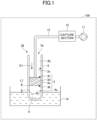
- FIG. 1 is a diagram illustrating the overall configuration of a separation device 10 including a separation instrument 3 and a separation system 100 according to the present embodiment.
- the separation system 100 is a device for separating a gaseous substance from a solution 4 in which the gaseous substance is dissolved and capturing the separated gaseous substance.
- the gaseous substances include volatile substances such as methanol, ethanol, acetonitrile, water, and dimethyl sulfoxide (DMSO), carbonic acid, oxygen, and the like.
- the separation system 100 includes a depressurization section 11 for depressurizing the inside of a container 2, a capture section 15 for capturing the gaseous substance, a pipe 12, and the separation device 10.
- the depressurization section 11 is, for example, an exhaust air pump.
- the pipe 12 is connected to the depressurization section 11.
- the capture section 15 is provided in the middle of the pipe 12.
- the capture section 15 is not a required element, and may be omitted when, for example, the separated gaseous substance may be released directly into the atmosphere without any problem.
- the end of the pipe 12 is inserted into the separation instrument 3.
- a valve (not illustrated) may be provided at an appropriate location on the pipe 12. The amount of drawn gas may be adjusted by adjusting the opening of the valve.
- the separation device 10 includes the container 2 and the separation instrument 3.
- the container 2 is, for example, a centrifuge tube made of glass, plastic, or the like, or a similar container.
- a general-purpose product for example, a Falcon tube
- the shape of the container is not limited to the one with a constant inner diameter.
- the container has a tapered shape that narrows toward the interior of the container from the opening, there is no problem when a separation instrument having a shape that can be brought into close contact with the inner diameter of the tapered shape is used. "That can be brought into close contact” means having airtightness to the extent that gas does not substantially flow in and out from the side surface of the separation instrument other than through gas introduction grooves formed in the side surface of the separation instrument. The gas introduction grooves will be described later.
- the solution 4 is contained in the container 2.
- the container 2 is supported by a support member (not illustrated) such that the bottom of the container 2 is immersed in a tank 14 of a water bath, for example.
- a support member not illustrated
- vaporization and separation of the gaseous substance such as the volatile substance from the solution 4 are promoted.
- the separation instrument 3 is immersed in the tank 14, but instead of immersing the separation instrument 3 in the tank 14, a bead bath in which aluminum beads are spread may be used, or the separation instrument 3 may be heated such as by applying hot air to the container 2. Heating may be unnecessary depending on the type of the solution 4 containing the gaseous substance, the outside temperature, and the like.
- the separation instrument 3 is inserted into an inner space 2b of the container 2.
- the separation instrument 3 is a columnar member that separates and discharges the dissolved gaseous substance from the solution 4 contained in the container 2.
- the separation instrument 3 is inserted from the opening 2a of the container 2 toward the bottom of the container 2 in an insertion direction D1, and is provided near the surface 4a at a predetermined distance L1 from the surface 4a of the solution 4 in the container 2.
- the predetermined distance L1 corresponds to the distance from the highest point of the surface 4a of the solution 4 due to the surface tension on the inner peripheral surface of the container 2 to a second end 3b of the separation instrument 3.
- the predetermined distance L1 is set to a value at which the separation instrument 3 is close to the surface 4a of the solution 4, and also, the predetermined distance L1 is set such that, when the depressurization section 11 operates and the solution 4 is swirled up by the gas blown into the container 2 through the separation instrument 3, the swirled solution 4 is not sucked into the pipe 12.
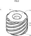
- FIG. 2 is a perspective view of the separation instrument 3.
- FIG. 3 is a side view of the separation instrument 3.
- the separation instrument 3 includes a first end 3c located on the side opposite to the solution 4 side of the separation instrument 3, the second end 3b located on the solution side of the separation instrument 3, the side surface 3a located between the first end 3c and the second end 3b, grooves 3d, and a through hole 3e.
- the material of the separation instrument 3 is not particularly limited, but is preferably a material that is stable even in contact with a solution.
- fluorinated resins such as fluorinated rubber, polytetrafluoroethylene (PTFE), and the like, are preferable.
- the material other than fluorinated materials include, depending on the type of solution, a general purpose rubber such as silicone rubber, polyisobutylene rubber, acrylic rubber, styrene-butadiene rubber, butadiene rubber, isoprene rubber, chloroprene rubber, and the like, or, a thermoplastic elastomer such as polyethylene elastomer, polyisobutylene elastomer, and the like.
- the grooves 3d are sloped grooves for introducing gases, which extends from the first end 3c to the second end 3b.
- the separation instrument 3 illustrated in FIG. 2 is formed with six grooves 3d.
- the grooves 3d are formed on the side surface 3a of the separation instrument 3 and tilt at a predetermined angle with respect to the second end 3b.
- the tilt angle ⁇ of the grooves 3d is preferably 10° to 45°, and more preferably 15° to 25° from the viewpoint of increasing the separation efficiency by the grooves 3d while increasing the flow rate of the gas introduced into the container 2.
- the grooves are one example of gas introduction grooves.
- the gas introduced into the grooves 3d is preferably air.
- an inert gas for example, nitrogen or argon gas.
- the entire container 2 into which the separation instrument 3 is inserted may be placed under an inert gas atmosphere.
- the grooves 3d extends from the first end 3c toward the second end 3b in a clockwise direction when viewed from the upper side of the separation instrument 3, but may extend in a counterclockwise direction.
- the number of the grooves 3d is preferably plural.
- the flow of the gas blown from a single groove tends to be uneven, and depending on the gas flow rate, the liquid surface may not be stable.
- the number of the grooves is preferably 2 to 10. In the case of 2 grooves, the interval thereof is preferably 180°, and in the case of 3 grooves, the interval thereof is preferably 120°.
- the gas grooves are preferably arranged at equal intervals in any of the cases of 4, 5, ..., and 10 grooves.
- the depth and width of the grooves 3d are suitably set depending on the dimensions of the separation instrument 3.
- the cross-sectional area of the grooves 3d is 0.4 to 10% of the cross-sectional area of the separation instrument 3, and more preferably 1.6 to 3.5% of the cross-sectional area of the separation instrument 3.
- the solution 4 blown up by the gas blown in from the grooves 3d may reach the top of the container 2 and enter the pump.
- the gas blown from the grooves 3d may hit only the upper portion of the solution 4, and only the upper portion of the solution 4 is stirred, resulting in an insufficient effect to promote vaporization of the gaseous substance.
- the plurality of grooves 3d have the same cross-sectional area.
- different cross-sectional areas if the number of the grooves is even, it is preferable to alternately combine grooves with a large cross-sectional area and grooves with a small cross-sectional area. For example, when there are six grooves, stable separation can be achieved by setting three grooves to have a larger cross-sectional area and the remaining three grooves to have a smaller cross-sectional area.
- the grooves 3d are preferably formed as a spiral on the side surface 3a of the separation instrument 3 from the first end 3c toward the second end 3b of the separation instrument 3.
- the side surface 3a contacts the inner peripheral surface 2c of the container 2 illustrated in FIG. 1 in a region between the first end 3c to the second end 3b. That is, the separation instrument 3 is formed so that the entire side surface 3a except for the grooves 3d is in contact with the inner peripheral surface 2c of the container 2. Thus, a space 3d1 (see FIG. 3 ) is formed between the grooves 3d and the inner peripheral surface 2c of the container 2. The space 3d1 communicates from the first end 3c to the second end 3b of the separation instrument 3, and serves as a path through which the gas is introduced.
- the gas introduced from the first end 3c to the grooves 3d of the separation instrument 3 is led to the second end 3b of the separation instrument 3, without being diffused to portions other than the grooves 3d (between the side surface 3a of the separation instrument 3 and the inner peripheral surface 2c of the container 2), and sprayed onto the solution 4.
- the through hole 3e is a discharge hole for discharging the gaseous substance separated from the solution 4 together with the gas introduced into the container 2 through the grooves 3d.
- the through hole 3e is formed between a center portion of the second end 3b and a center portion of the first end 3c.
- the cross-sectional area of the through hole 3e is the same as or larger than the total cross-sectional area of the grooves.
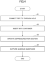
- FIG. 4 is a flow chart illustrating operation of the separation system 100.
- FIG. 5 is a diagram illustrating a state of a gas flowing through the grooves 3d of the separation instrument 3 and the like when the separation system 100 is in operation.
- step S1 With the pipe 12, which extends from the capture section 15, inserted into the through hole 3e of the separation instrument 3 (step S1), the separation instrument 3 is inserted into the container 2 (step S2).
- the separation instrument 3 is disposed so as to be close to the solution 4, and the depressurizing section 11 is operated (step S3).
- the pressure inside the container 2 is reduced, and the gas on the first end 3c side of the separation instrument 3 is drawn into the grooves 3d and blown into the container 2 at high speed through the grooves 3d.
- Insertion of the separation instrument may be performed as follows. First, the separation instrument is positioned away from the solution surface and the depressurization section is operated. Then the separation instrument is gradually brought closer to the solution surface while the operation of the depressurization section is kept constant, and the separation instrument is held at such a distance to the solution surface that the liquid does not get caught in the through hole.
- the separation device may be positioned near the solution surface while the operation of the depressurization section is kept low. Then the exhaust amount of the depressurization section is gradually increased, and the operation of the depressurization section is made constant with the exhaust amount of the depressurization section to such an extent that the liquid does not get caught in the through hole.
- the gaseous substance can be stably separated by reproducing the position of the separation instrument in proximity to the exhaust amount of the above-described constant exhaust amount of the depressurization section.
- the gas blown in at high speed reaches the solution 4, for example, by spiraling along the inner peripheral surface 2c of the container 2.
- the solution 4 is swirled up by the airflow and stirred, thereby promoting the vaporization of the gaseous substance.
- the vaporized gaseous substance is captured by the capture section 15 through the pipe 12 (step S4).
- FIG. 6 is a perspective view of a separation instrument 3A according to Comparative Example 1, which is a prior art.
- FIG. 7 is a diagram illustrating a configuration example of a separation system 100A using the separation instrument 3A illustrated in FIG. 6 .
- the separation instrument 3A is formed into a truncated cone shape so as to block the opening 2a of the container 2.
- the grooves 3d are formed in the side surface 3a of the separation instrument 3A.
- the separation instrument 3A having such a shape When the separation instrument 3A having such a shape is attached to the opening 2a of the container 2, because the inner diameter of the container 2 is constant from the opening 2a to the vicinity of the bottom, a gap GP is formed between the side surface 3a of the separation instrument 3A and the inner peripheral surface 2c of the container 2. In addition, because the separation instrument 3A is provided near the opening 2a of the container 2, the distance L2 from the second end 3b of the separation instrument 3A to the surface 4a of the solution 4 is increased.
- the vicinity of the opening of the container 2 may formed in a mortar shape.
- the manufacturing cost of the container 2 is increased.
- the concentration time of the solution 4 was about 200 minutes for the separation instrument 3A and about 39 minutes for the separation instrument 3. That is, it was confirmed that the concentration time of the solution 4 can be reduced to one-fifth by the separation instrument 3 according to the present embodiment.
- the number of grooves is at least two or more.
- FIG. 8 illustrates the relationship between the number of grooves 3d and the concentration time of the solution 4 (concentration performance) when a conical tube is used as the container.
- the conical tube has a tapered tip (the tip is rounded) as compared with the container illustrated in FIG. 1 and the like.
- the conical tube used in the experiment has a total length of about 170 mm, an inner diameter of about 14 mm, an inner diameter of about 5 mm on the tip side, and a tapered slope length of about 22 mm.
- Examples 1 to 9 and Comparative Example 1 differed only in the number of grooves of the separation instrument, and used the same shape. Water was used as the liquid.
- An inclination angle ⁇ of the grooves 3d was about 20°, and the thickness and depth of the grooves 3d were designed so that the cross-sectional area of the entire grooves is 6.25 mm 2 even when the number of grooves was different.
- the length of the separation instrument 3 and the like is designed according to the type and amount of the liquid to be used.
- the length (distance L1) from the separation instrument 3 to the solution 4 when standing still during the measurement of FIG. 8 was the same and was set to about 24 mm.
- the distance from the separation instrument 3 to the solution 4 varies depending on the type of the liquid, the size of the container, and the like. It is preferable that the distance does not exceed twice the inner diameter of the container, and more preferably, the distance is approximately the same as the inner diameter of the container. In the case of the conical tube, it was preferable that the distance was the inner diameter of the container (other than the conical part) or more.
- the time n in FIG. 8 represents the time (sec) until 500 ul of tap water (solution) placed in a 14 ml conical tube dries up. More specifically, the separation instrument 3 having each number of grooves was placed in the conical tube, and the liquid surface was stirred by drawing with a vacuum pump, and the time required for the water to evaporate was measured.
- the scattering was evaluated using the following criteria.
- FIG. 9 compares the concentration rate of a methanol (MeOH) solution when there is one groove (prior art), to when there are two or eight grooves according to the present embodiment. All of the separation instruments have the same outer shape, and only the number of grooves is different.
- the P2 plug is a conventional separation instrument (plug) that also functions as a lid.
- the 8 grooves test tube and the 2 grooves test tube are the separation instruments (plugs) of the present embodiment, which have the same diameter and differ only in the number of grooves.
- the concentration rate was measured as follows. 1 ml of methanol (MeOH) with a concentration of 99.7% was placed in a 10 ml container and the gas (air) flow was 18 L/min.
- the flow rate is set to 15 L/min at first and then to 18 L/min after 5 minutes.
- the concentration rate was measured by measuring the volume of the tare with a precision scale every hour and measuring the weight.
- "Peltier -10°C” indicates the preset temperature when the vaporized methanol gas drawn into the vacuum pump is liquefied by the Peltier device, and was set to - 10°C.
- the separation instrument (plug) having a plurality of grooves significantly reduces the concentration time compared to a conventional single-grooved plug.
- the concentration time can be substantially the same as for the plug with 8 grooves.
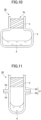
- FIG. 10 is a diagram illustrating a first variation of the container 2. As illustrated in FIG. 10 , even when the separation instrument 3 is applied to the container 2 having a larger bottom cross-sectional area than the cross-sectional area of the opening 2a, the separation instrument 3 can be provided near the solution 4. By bringing the inner peripheral surface of the container 2 in the vicinity of the opening into contact with the entire side surface 3a of the separation instrument 3, the aforementioned effects can be obtained.
- FIG. 11 is a diagram illustrating a second variation of the container 2.
- the container 2 illustrated in FIG. 11 has a tubular member 2A and a bottomed member 2B that are vertically divided into two parts, and have shapes that can be connected to each other with respective flanges 2d.
- the container 2 is completed as follows.
- the tubular member 2A on the upper side is connected to the bottomed member 2B on the lower side in a state in which the tubular member 2A is provided with the separation instrument 3.
- the respective flanges 2d are fixed to each other by a member such as a screw or a clip, for example.
- the separation instrument 3 may be provided near the solution 4.
- FIG. 12 is a diagram illustrating a variation of the separation instrument 3.
- the separation instrument 3 illustrated in FIG. 12 includes a mounting portion 3f to facilitate attachment and detachment of the separation instrument 3.
- the mounting portion 3f is a tubular member that can be grasped by a guide member (not illustrated).
- the guide member is a tool for inserting the separation instrument 3 into the container 2 or taking out the separation instrument 3 from the container 2 while gripping the mounting portion 3f of the separation instrument 3.
- a recess 3f1 with which the gripping portion of the guide member is engaged, is formed on the outer peripheral portion of the mounting portion 3f.
- the configuration of the separation instrument 3 in this manner facilitates, among other things, removal of the separation instrument 3 from the inside of the container 2.
- the structure illustrated in the above-described embodiment is an example of the contents of the present disclosure, and it may be combined with another known art, or part of the structure may be omitted or changed without departing from the gist of the present disclosure.
Landscapes
- Chemical & Material Sciences (AREA)
- Chemical Kinetics & Catalysis (AREA)
- Health & Medical Sciences (AREA)
- Clinical Laboratory Science (AREA)
- Analytical Chemistry (AREA)
- General Health & Medical Sciences (AREA)
- Hematology (AREA)
- Sampling And Sample Adjustment (AREA)
- Centrifugal Separators (AREA)
Description
- The present invention relates to a separation device and a separation method.
-
PTL 1 discloses a stopper for closing an opening of a container that contains a solution containing a volatile substance. The stopper includes a through-pore for exhausting gas, a gas inlet port, a gas outlet port, and a spiral groove connecting the gas inlet port to the gas outlet port, the spiral groove being formed at the side surface of the stopper. According to the stopper ofPTL 1, external gas is introduced from the gas inlet port into the space between an inner peripheral surface of the container and the groove, and blown into the container through the gas outlet port. When the gas rotates spirally along the inner peripheral surface of the container, the solution is swirled up and the volatile substance contained in the solution is vaporized and separated. - [PTL 1]
Japanese Patent No.4763805 JP2014104412 - However, because the stopper disclosed in
PTL 1 has a configuration in which one groove for spirally rotating the gas is formed on the stopper attached to the opening of the container containing the solution, it is difficult for the gas reaching the liquid surface to flow uniformly. This may increase the time needed to separate the gaseous substance in the solution. - The present disclosure has been made in view of the foregoing, and an object thereof is to obtain a separation device that requires less time to separate a gaseous substance dissolved in a solution.
- In order to solve the above problem, according to the present disclosure, a separation device is defined as in
claim 1 and a separation method is defined as inclaim 4. - According to the present disclosure, the time needed to separate a gaseous substance dissolved in a solution can be reduced.
-
- [
FIG. 1 ]
FIG. 1 is a diagram illustrating the overall configuration of aseparation device 10 including aseparation instrument 3 and aseparation system 100 according to the present embodiment; - [
FIG. 2 ]
FIG. 2 is a perspective view of theseparation instrument 3; - [
FIG. 3 ]
FIG. 3 is a side view of theseparation instrument 3; - [
FIG. 4 ]
FIG. 4 is a flow chart illustrating the operation of theseparation system 100; - [
FIG. 5 ]
FIG. 5 is a diagram illustrating a state of a gas flowing throughgrooves 3d and the like of theseparation instrument 3 during operation of theseparation system 100; - [
FIG. 6 ]
FIG. 6 is a perspective view of aseparation instrument 3A according to Comparative Example 1; - [
FIG. 7 ]
FIG. 7 is a diagram illustrating the configuration example of aseparation system 100A using theseparation instrument 3A; - [
FIG. 8 ]
FIG. 8 is a table of Examples and Comparative Examples illustrating the relationship between the number of grooves of a separation instrument and the concentration time of asolution 4 at a same gas flow rate; - [
FIG. 9 ]
FIG. 9 is a graph of another embodiment illustrating the relationship between a gas flow rate, the number of grooves in a separation instrument, and the concentration time of thesolution 4; - [
FIG. 10 ]
FIG. 10 is a diagram illustrating a first variation of acontainer 2; - [
FIG. 11 ]
FIG. 11 is a diagram illustrating a second variation of thecontainer 2; and - [
FIG. 12 ]
FIG. 12 is a diagram illustrating a variation of theseparation instrument 3. - Hereinafter, embodiments for carrying out the present disclosure will be described with reference to the drawings. The present invention is not limited to the particulars of the described embodiments. In the description of the figures below, the same or similar parts are given the same or similar reference numerals. The following embodiments exemplify apparatuses and methods that embody the technical idea of the present disclosure. The technical idea of the present disclosure is not limited to the specifics of the structure, arrangement, and the like, of the components as described below. Various modifications can be made to the technical idea of the present disclosure within the technical scope defined by the claims.
-
FIG. 1 is a diagram illustrating the overall configuration of aseparation device 10 including aseparation instrument 3 and aseparation system 100 according to the present embodiment. Theseparation system 100 is a device for separating a gaseous substance from asolution 4 in which the gaseous substance is dissolved and capturing the separated gaseous substance. Examples of the gaseous substances include volatile substances such as methanol, ethanol, acetonitrile, water, and dimethyl sulfoxide (DMSO), carbonic acid, oxygen, and the like. - The
separation system 100 includes adepressurization section 11 for depressurizing the inside of acontainer 2, acapture section 15 for capturing the gaseous substance, apipe 12, and theseparation device 10. Thedepressurization section 11 is, for example, an exhaust air pump. Thepipe 12 is connected to thedepressurization section 11. Thecapture section 15 is provided in the middle of thepipe 12. Thecapture section 15 is not a required element, and may be omitted when, for example, the separated gaseous substance may be released directly into the atmosphere without any problem. The end of thepipe 12 is inserted into theseparation instrument 3. A valve (not illustrated) may be provided at an appropriate location on thepipe 12. The amount of drawn gas may be adjusted by adjusting the opening of the valve. - The
separation device 10 includes thecontainer 2 and theseparation instrument 3. Thecontainer 2 is, for example, a centrifuge tube made of glass, plastic, or the like, or a similar container. In the present embodiment, a general-purpose product (for example, a Falcon tube) having a constant inner diameter from the opening 2a of thecontainer 2 to the vicinity of the bottom is used as thecontainer 2. The shape of the container is not limited to the one with a constant inner diameter. In the case where the container has a tapered shape that narrows toward the interior of the container from the opening, there is no problem when a separation instrument having a shape that can be brought into close contact with the inner diameter of the tapered shape is used. "That can be brought into close contact" means having airtightness to the extent that gas does not substantially flow in and out from the side surface of the separation instrument other than through gas introduction grooves formed in the side surface of the separation instrument. The gas introduction grooves will be described later. - The
solution 4 is contained in thecontainer 2. Thecontainer 2 is supported by a support member (not illustrated) such that the bottom of thecontainer 2 is immersed in atank 14 of a water bath, for example. By heating the water in thetank 14, vaporization and separation of the gaseous substance such as the volatile substance from thesolution 4 are promoted. In the example ofFIG. 1 , theseparation instrument 3 is immersed in thetank 14, but instead of immersing theseparation instrument 3 in thetank 14, a bead bath in which aluminum beads are spread may be used, or theseparation instrument 3 may be heated such as by applying hot air to thecontainer 2. Heating may be unnecessary depending on the type of thesolution 4 containing the gaseous substance, the outside temperature, and the like. - The
separation instrument 3 is inserted into aninner space 2b of thecontainer 2. Theseparation instrument 3 is a columnar member that separates and discharges the dissolved gaseous substance from thesolution 4 contained in thecontainer 2. Theseparation instrument 3 is inserted from theopening 2a of thecontainer 2 toward the bottom of thecontainer 2 in an insertion direction D1, and is provided near thesurface 4a at a predetermined distance L1 from thesurface 4a of thesolution 4 in thecontainer 2. The predetermined distance L1 corresponds to the distance from the highest point of thesurface 4a of thesolution 4 due to the surface tension on the inner peripheral surface of thecontainer 2 to asecond end 3b of theseparation instrument 3. For example, the predetermined distance L1 is set to a value at which theseparation instrument 3 is close to thesurface 4a of thesolution 4, and also, the predetermined distance L1 is set such that, when thedepressurization section 11 operates and thesolution 4 is swirled up by the gas blown into thecontainer 2 through theseparation instrument 3, the swirledsolution 4 is not sucked into thepipe 12. - For example, by reducing the discharge amount of the
depressurization section 11, the flow of the gas blown through theside surface 3a of theseparation instrument 3 is decreased. Therefore, the liquid surface is not heavily swirled up, and the length of L1 can be reduced. However, when the exhaust amount (gas blowing amount) is too small, the stirring action of the solution will hardly work and the solution will be in a state close to standing still, so it will take a long time to separate the gaseous substance. - Conversely, when the exhaust amount by the
depressurization section 11 is too large, the gas is blown at high speed from theside surface 3a of theseparation instrument 3, and the liquid surface is heavily stirred and scattered. Some of the scattered solution not only adheres to the inner wall (the innerperipheral surface 2c) of thecontainer 2, but is also drawn at high speed through the discharge hole. As a result, even when the length of L1 is increased, the gaseous substance is not separated so much, and the solution is easily sucked into thepipe 12 as is, which is not preferable. In addition, as will be described later, in a case where the gas flow blown from theside surface 3a of theseparation instrument 3 is uneven, even when the length of L1 is increased, the gaseous substance is not separated so much, and the solution is easily sucked into thepipe 12 as is, which is not preferable. Accordingly, a configuration in which the separation instrument is arranged near the liquid surface (thesurface 4a of the solution 4) is preferable. - Next, a configuration example of the
separation instrument 3 will be described with reference toFIGS. 2 and3 .FIG. 2 is a perspective view of theseparation instrument 3.FIG. 3 is a side view of theseparation instrument 3. - The
separation instrument 3 includes afirst end 3c located on the side opposite to thesolution 4 side of theseparation instrument 3, thesecond end 3b located on the solution side of theseparation instrument 3, theside surface 3a located between thefirst end 3c and thesecond end 3b,grooves 3d, and a throughhole 3e. - The material of the
separation instrument 3 is not particularly limited, but is preferably a material that is stable even in contact with a solution. For example, fluorinated resins such as fluorinated rubber, polytetrafluoroethylene (PTFE), and the like, are preferable. Examples of the material other than fluorinated materials include, depending on the type of solution, a general purpose rubber such as silicone rubber, polyisobutylene rubber, acrylic rubber, styrene-butadiene rubber, butadiene rubber, isoprene rubber, chloroprene rubber, and the like, or, a thermoplastic elastomer such as polyethylene elastomer, polyisobutylene elastomer, and the like. - The
grooves 3d are sloped grooves for introducing gases, which extends from thefirst end 3c to thesecond end 3b. Theseparation instrument 3 illustrated inFIG. 2 is formed with sixgrooves 3d. Thegrooves 3d are formed on theside surface 3a of theseparation instrument 3 and tilt at a predetermined angle with respect to thesecond end 3b. The tilt angle θ of thegrooves 3d is preferably 10° to 45°, and more preferably 15° to 25° from the viewpoint of increasing the separation efficiency by thegrooves 3d while increasing the flow rate of the gas introduced into thecontainer 2. The grooves are one example of gas introduction grooves. - The gas introduced into the
grooves 3d is preferably air. Depending on the type of the gaseous substance, it may be necessary to separate the gaseous substance from the solution under an inert gas (for example, nitrogen or argon gas). In this case, at least, theentire container 2 into which theseparation instrument 3 is inserted may be placed under an inert gas atmosphere. Thegrooves 3d extends from thefirst end 3c toward thesecond end 3b in a clockwise direction when viewed from the upper side of theseparation instrument 3, but may extend in a counterclockwise direction. - The number of the
grooves 3d is preferably plural. The flow of the gas blown from a single groove tends to be uneven, and depending on the gas flow rate, the liquid surface may not be stable. The number of the grooves is preferably 2 to 10. In the case of 2 grooves, the interval thereof is preferably 180°, and in the case of 3 grooves, the interval thereof is preferably 120°. The gas grooves are preferably arranged at equal intervals in any of the cases of 4, 5, ..., and 10 grooves. - The depth and width of the
grooves 3d are suitably set depending on the dimensions of theseparation instrument 3. The cross-sectional area of thegrooves 3d is 0.4 to 10% of the cross-sectional area of theseparation instrument 3, and more preferably 1.6 to 3.5% of the cross-sectional area of theseparation instrument 3. When the cross-sectional area of thegrooves 3d is less than 0.4% of the cross-sectional area of theseparation instrument 3, thesolution 4 blown up by the gas blown in from thegrooves 3d may reach the top of thecontainer 2 and enter the pump. In contrast, when the cross-sectional area of thegrooves 3d exceeds 10% of the cross-sectional area of theseparation instrument 3, the gas blown from thegrooves 3d may hit only the upper portion of thesolution 4, and only the upper portion of thesolution 4 is stirred, resulting in an insufficient effect to promote vaporization of the gaseous substance. - It is preferable that the plurality of
grooves 3d have the same cross-sectional area. When different cross-sectional areas are used, if the number of the grooves is even, it is preferable to alternately combine grooves with a large cross-sectional area and grooves with a small cross-sectional area. For example, when there are six grooves, stable separation can be achieved by setting three grooves to have a larger cross-sectional area and the remaining three grooves to have a smaller cross-sectional area. - The
grooves 3d are preferably formed as a spiral on theside surface 3a of theseparation instrument 3 from thefirst end 3c toward thesecond end 3b of theseparation instrument 3. - The
side surface 3a contacts the innerperipheral surface 2c of thecontainer 2 illustrated inFIG. 1 in a region between thefirst end 3c to thesecond end 3b. That is, theseparation instrument 3 is formed so that theentire side surface 3a except for thegrooves 3d is in contact with the innerperipheral surface 2c of thecontainer 2. Thus, a space 3d1 (seeFIG. 3 ) is formed between thegrooves 3d and the innerperipheral surface 2c of thecontainer 2. The space 3d1 communicates from thefirst end 3c to thesecond end 3b of theseparation instrument 3, and serves as a path through which the gas is introduced. Accordingly, the gas introduced from thefirst end 3c to thegrooves 3d of theseparation instrument 3 is led to thesecond end 3b of theseparation instrument 3, without being diffused to portions other than thegrooves 3d (between theside surface 3a of theseparation instrument 3 and the innerperipheral surface 2c of the container 2), and sprayed onto thesolution 4. - The through
hole 3e is a discharge hole for discharging the gaseous substance separated from thesolution 4 together with the gas introduced into thecontainer 2 through thegrooves 3d. The throughhole 3e is formed between a center portion of thesecond end 3b and a center portion of thefirst end 3c. - The cross-sectional area of the through
hole 3e is the same as or larger than the total cross-sectional area of the grooves. - When the gas is blown from the
side surface 3a of theseparation instrument 3 to the solution surface (thesurface 4a of the solution 4) as a swirling flow, the swirling flow of the gas induces rotational movement of the entire solution. As a result of the rotational movement of the solution, a centrifugal force acts on the solution on the side of the inner peripheral surface C2 of thecontainer 2, which acts to raise the liquid level. However, the swirling flow of the gas exerts a downward force, and the gas is drawn from the throughhole 3e formed in the center portion of theseparation instrument 3, thereby reducing the air pressure near the center portion of the liquid surface. Further, by arranging theseparation instrument 3 near the liquid surface, it is possible to prevent the liquid surface from scattering. Therefore, even when a certain amount of gas is blown in, due to the balance of these factors, the liquid surface does not fluctuate significantly. As a result, it is possible to stably maintain the state in which the lower end of theseparation instrument 3 is close to the liquid surface. - Next, the operation of the
separation system 100 will be described with reference toFIGS. 4 and5 .FIG. 4 is a flow chart illustrating operation of theseparation system 100.FIG. 5 is a diagram illustrating a state of a gas flowing through thegrooves 3d of theseparation instrument 3 and the like when theseparation system 100 is in operation. - With the
pipe 12, which extends from thecapture section 15, inserted into the throughhole 3e of the separation instrument 3 (step S1), theseparation instrument 3 is inserted into the container 2 (step S2). - As illustrated in
FIG. 1 , theseparation instrument 3 is disposed so as to be close to thesolution 4, and the depressurizingsection 11 is operated (step S3). As a result, the pressure inside thecontainer 2 is reduced, and the gas on thefirst end 3c side of theseparation instrument 3 is drawn into thegrooves 3d and blown into thecontainer 2 at high speed through thegrooves 3d. - Insertion of the separation instrument may be performed as follows. First, the separation instrument is positioned away from the solution surface and the depressurization section is operated. Then the separation instrument is gradually brought closer to the solution surface while the operation of the depressurization section is kept constant, and the separation instrument is held at such a distance to the solution surface that the liquid does not get caught in the through hole. Alternatively, the separation device may be positioned near the solution surface while the operation of the depressurization section is kept low. Then the exhaust amount of the depressurization section is gradually increased, and the operation of the depressurization section is made constant with the exhaust amount of the depressurization section to such an extent that the liquid does not get caught in the through hole.
- When the same amount of the same solution is taken into the container, the gaseous substance can be stably separated by reproducing the position of the separation instrument in proximity to the exhaust amount of the above-described constant exhaust amount of the depressurization section. In addition, it is possible to separate stable gaseous substances by reproducing the position of the separation instrument close to the liquid surface with the above-described constant exhaust amount of the depressurization section.
- The gas blown in at high speed reaches the
solution 4, for example, by spiraling along the innerperipheral surface 2c of thecontainer 2. As a result, thesolution 4 is swirled up by the airflow and stirred, thereby promoting the vaporization of the gaseous substance. The vaporized gaseous substance is captured by thecapture section 15 through the pipe 12 (step S4). - Next, Comparative Example 1 of the
separation instrument 3 according to the present embodiment will be described with reference toFIGS. 6 and7 .FIG. 6 is a perspective view of aseparation instrument 3A according to Comparative Example 1, which is a prior art.FIG. 7 is a diagram illustrating a configuration example of aseparation system 100A using theseparation instrument 3A illustrated inFIG. 6 . - The
separation instrument 3A is formed into a truncated cone shape so as to block theopening 2a of thecontainer 2. Thegrooves 3d are formed in theside surface 3a of theseparation instrument 3A. - When the
separation instrument 3A having such a shape is attached to theopening 2a of thecontainer 2, because the inner diameter of thecontainer 2 is constant from theopening 2a to the vicinity of the bottom, a gap GP is formed between theside surface 3a of theseparation instrument 3A and the innerperipheral surface 2c of thecontainer 2. In addition, because theseparation instrument 3A is provided near theopening 2a of thecontainer 2, the distance L2 from thesecond end 3b of theseparation instrument 3A to thesurface 4a of thesolution 4 is increased. - The air flow when the
depressurization section 11 is operated will be described with reference toFIG. 7 . When thedepressurization section 11 is operated while theseparation instrument 3A is attached to thecontainer 2, the inside of thecontainer 2 is depressurized and the gas at thefirst end 3c side of theseparation instrument 3A is taken into thegrooves 3d. At this time, a part of the gas passing through thegrooves 3d leaks out from the gap GP, and furthermore, because the distance L2 is long, so that the gas momentum is greatly reduced before reaching thesolution 4. Therefore, it may take a long time to vaporize the gaseous substance dissolved in thesolution 4. - In order to eliminate the gap GP, the vicinity of the opening of the
container 2 may formed in a mortar shape. However, because a special shape of thecontainer 2 is required, the manufacturing cost of thecontainer 2 is increased. - Also, even when such a
container 2 is manufactured, because the distance L2 from theseparation instrument 3A to thesolution 4 is long, the momentum of the gas blown into thecontainer 2 is greatly reduced before reaching thesolution 4. - When the
separation instrument 3A of Comparative Example 1 and theseparation instrument 3 according to the present embodiment were used under the same conditions, the concentration time of thesolution 4 was about 200 minutes for theseparation instrument 3A and about 39 minutes for theseparation instrument 3. That is, it was confirmed that the concentration time of thesolution 4 can be reduced to one-fifth by theseparation instrument 3 according to the present embodiment. - In the case of
FIG. 7 , the above-described problem can be solved when the opening of the container has a shape that expands in diameter upwardly, and the side surface of theseparation instrument 3A and the opening of the container are in close contact with each other except at the groove. However, as illustrated in Comparative Example 1 below, in the case of a single groove, the swirling flow is uneven, so the state of the liquid surface tends to be unstable. - As illustrated below, the number of grooves is at least two or more.
- Hereinafter, the present invention will be described specifically with reference to examples.
FIG. 8 illustrates the relationship between the number ofgrooves 3d and the concentration time of the solution 4 (concentration performance) when a conical tube is used as the container. - The conical tube has a tapered tip (the tip is rounded) as compared with the container illustrated in
FIG. 1 and the like. The conical tube used in the experiment has a total length of about 170 mm, an inner diameter of about 14 mm, an inner diameter of about 5 mm on the tip side, and a tapered slope length of about 22 mm. - Examples 1 to 9 and Comparative Example 1 differed only in the number of grooves of the separation instrument, and used the same shape. Water was used as the liquid.
- An inclination angle θ of the
grooves 3d was about 20°, and the thickness and depth of thegrooves 3d were designed so that the cross-sectional area of the entire grooves is 6.25 mm2 even when the number of grooves was different. The length of theseparation instrument 3 and the like is designed according to the type and amount of the liquid to be used. - The length (distance L1) from the
separation instrument 3 to thesolution 4 when standing still during the measurement ofFIG. 8 was the same and was set to about 24 mm. The distance from theseparation instrument 3 to thesolution 4 varies depending on the type of the liquid, the size of the container, and the like. It is preferable that the distance does not exceed twice the inner diameter of the container, and more preferably, the distance is approximately the same as the inner diameter of the container. In the case of the conical tube, it was preferable that the distance was the inner diameter of the container (other than the conical part) or more. - Five measurements were performed under the same conditions, and the average value was determined.
- The time n in
FIG. 8 represents the time (sec) until 500 ul of tap water (solution) placed in a 14 ml conical tube dries up. More specifically, theseparation instrument 3 having each number of grooves was placed in the conical tube, and the liquid surface was stirred by drawing with a vacuum pump, and the time required for the water to evaporate was measured. - In
FIG. 8 , the scattering was evaluated using the following criteria. - EXCELLENT: The liquid surface (the water surface) was at a position of 17 mm, and the solution was uniformly stirred without scattering.
- GOOD: The liquid surface of the solution was at a position of 20 mm, and the solution was scattered to some extent, but did not reach the pipe.
- NOT GOOD: The liquid surface was at a position of 24 mm, and the solution was violently scattered from the top of the separation instrument to the pipe, and the solution also adhered to the pipe (the remaining solution was less due to the scattering, which greatly reduced the concentration time).
- From the above, it was confirmed that the gaseous substances can be efficiently separated and vaporized when the number of grooves is two or more. In addition, it was found that in a case where the number of grooves is 2 to 10, when the number of grooves is 2, 6, 7, or 8, concentration can be performed in a relatively short time.
-
FIG. 9 compares the concentration rate of a methanol (MeOH) solution when there is one groove (prior art), to when there are two or eight grooves according to the present embodiment. All of the separation instruments have the same outer shape, and only the number of grooves is different. The P2 plug is a conventional separation instrument (plug) that also functions as a lid. The 8 grooves test tube and the 2 grooves test tube are the separation instruments (plugs) of the present embodiment, which have the same diameter and differ only in the number of grooves. - As a condition, the concentration rate was measured as follows. 1 ml of methanol (MeOH) with a concentration of 99.7% was placed in a 10 ml container and the gas (air) flow was 18 L/min.
- As for the number of grooves being two, an example is illustrated in which the flow rate is set to 15 L/min at first and then to 18 L/min after 5 minutes.
- The concentration rate was measured by measuring the volume of the tare with a precision scale every hour and measuring the weight. "Peltier -10°C" indicates the preset temperature when the vaporized methanol gas drawn into the vacuum pump is liquefied by the Peltier device, and was set to - 10°C.
- From
FIG. 9 , it can be seen that the separation instrument (plug) having a plurality of grooves according to the present embodiment significantly reduces the concentration time compared to a conventional single-grooved plug. - In the case of 2 grooves, it is indicated that, when the flow rate is initially 15 l/min and 18 l/min after 5 minutes, the concentration time can be substantially the same as for the plug with 8 grooves.
- In this manner, by changing the flow rate from low to high, it is possible to efficiently perform concentration.
- Next, a variation of the
container 2 will be described with reference toFIGS. 10 and 11 . -
FIG. 10 is a diagram illustrating a first variation of thecontainer 2. As illustrated inFIG. 10 , even when theseparation instrument 3 is applied to thecontainer 2 having a larger bottom cross-sectional area than the cross-sectional area of theopening 2a, theseparation instrument 3 can be provided near thesolution 4. By bringing the inner peripheral surface of thecontainer 2 in the vicinity of the opening into contact with theentire side surface 3a of theseparation instrument 3, the aforementioned effects can be obtained. -
FIG. 11 is a diagram illustrating a second variation of thecontainer 2. Thecontainer 2 illustrated inFIG. 11 has atubular member 2A and a bottomedmember 2B that are vertically divided into two parts, and have shapes that can be connected to each other withrespective flanges 2d. Thecontainer 2 is completed as follows. Thetubular member 2A on the upper side is connected to the bottomedmember 2B on the lower side in a state in which thetubular member 2A is provided with theseparation instrument 3. Then, therespective flanges 2d are fixed to each other by a member such as a screw or a clip, for example. Even when thecontainer 2 that can be divided into upper and lower parts is used in this manner, theseparation instrument 3 may be provided near thesolution 4. By bringing the inner peripheral surface of thetubular member 2A in contact with theentire side surface 3a of theseparation instrument 3, the aforementioned effect can be obtained. -
FIG. 12 is a diagram illustrating a variation of theseparation instrument 3. Theseparation instrument 3 illustrated inFIG. 12 includes a mountingportion 3f to facilitate attachment and detachment of theseparation instrument 3. The mountingportion 3f is a tubular member that can be grasped by a guide member (not illustrated). The guide member is a tool for inserting theseparation instrument 3 into thecontainer 2 or taking out theseparation instrument 3 from thecontainer 2 while gripping the mountingportion 3f of theseparation instrument 3. For example, a recess 3f1, with which the gripping portion of the guide member is engaged, is formed on the outer peripheral portion of the mountingportion 3f. The configuration of theseparation instrument 3 in this manner facilitates, among other things, removal of theseparation instrument 3 from the inside of thecontainer 2. - The structure illustrated in the above-described embodiment is an example of the contents of the present disclosure, and it may be combined with another known art, or part of the structure may be omitted or changed without departing from the gist of the present disclosure.
- The present application claims priority to
Japanese Patent Application No. 2020-178774, filed October 26, 2020 -
- 2
- Container
- 2a
- Opening
- 2c
- Inner peripheral surface
- 3
- Separation instrument
- 3a
- Side surface
- 3b
- Second end
- 3c
- First end
- 3d
- Grooves
- 3d1
- Space
- 3e
- Through hole
- 4
- Solution
- 4a
- Surface
- 10
- Separation device
- 11
- Depressurization section
- 100
- Separation system
- L1
- Distance
Claims (4)
- A separation device (10) including a separation instrument (3) and a container (2), the separation instrument (3) being configured to separate a gaseous substance from a solution (4) contained in the container (2), the separation instrument (3) being a cylindrical columnar member and comprising:a first end (3c);a second end (3b); anda side surface (3a) provided between the first end (3c) and the second end (3b), whereina plurality of sloped gas introduction grooves (3d) configured to swirl a gas and introduce the gas into the container (2) are formed on the side surface (3a) between the first end (3c) and the second end (3b), wherein a cross-sectional area of the grooves (3d) is 0.4 to 10% of a cross-sectional area of the separation instrument (3),a discharge hole (3e) configured to discharge the gaseous substance separated from the solution (4) together with the gas is formed between a center portion of the second end (3b) and a center portion of the first end (3c), wherein a cross-sectional area of the discharge hole (3e) is the same as or larger than the cross-sectional area of the grooves (3d), andthe side surface (3a) is configured to contact an inner peripheral surface (2c) of the container (2) in a region between the first end (3c) and the second end (3b), wherein the entire side surface (3a) except for the grooves (3d) is in contact with the inner peripheral surface (2c) of the container (2).
- The separation device (10)) according to claim 1, wherein a number of the gas introduction grooves (3d) is 2 to 10.
- A separation system (100) including the separation device (10) of any one of claims 1 to 2 and a depressurization section (11) configured to depressurize the container (2).
- A separation method comprising:providing, in a container (2) containing a solution (4) in which a gaseous substance is dissolved, a separation instrument (3) near a surface (4a) of the solution (4) in a state where a side surface (3a) of the separation instrument (3) is in contact with an inner peripheral surface (2c) of the container (2), the separation instrument (3) being a cylindrical columnar member and having a plurality of sloped gas swirl grooves (3d) formed on the side surface (3a), wherein the entire side surface (3a) except for the grooves (3d) is in contact with the inner peripheral surface (2c) of the container (2), wherein a cross-sectional area of the grooves (3d) is 0.4 to 10% of a cross-sectional area of the separation instrument (3); andswirling a gas, which is introduced between the container (2) and the surface (4a) of the solution (4) through the gas swirl grooves (3d), along the inner peripheral surface (2c) of the container (2) and blowing the gas onto the surface (4a) of the solution (4), thereby separating the gaseous substance from the solution (4) and exhausting the gaseous substance separated from the solution (4) together with the gas through a through hole (3e) formed in the separation instrument (3) between a center portion of a second end (3b) of the separation instrument (3) and a center portion of a first end (3c) of the separation instrument (3), wherein a cross-sectional area of the through hole (3e) is the same as or larger than the cross-sectional area of the grooves (3d).
Applications Claiming Priority (2)
| Application Number | Priority Date | Filing Date | Title |
|---|---|---|---|
| JP2020178774 | 2020-10-26 | ||
| PCT/JP2021/039565 WO2022092123A1 (en) | 2020-10-26 | 2021-10-26 | Separation instrument, separation device, separation system, and separation method |
Publications (3)
| Publication Number | Publication Date |
|---|---|
| EP4162999A4 EP4162999A4 (en) | 2023-04-12 |
| EP4162999A1 EP4162999A1 (en) | 2023-04-12 |
| EP4162999B1 true EP4162999B1 (en) | 2024-06-05 |
Family
ID=81383982
Family Applications (1)
| Application Number | Title | Priority Date | Filing Date |
|---|---|---|---|
| EP21886241.5A Active EP4162999B1 (en) | 2020-10-26 | 2021-10-26 | Separation device and separation method |
Country Status (7)
| Country | Link |
|---|---|
| US (1) | US12157070B2 (en) |
| EP (1) | EP4162999B1 (en) |
| JP (1) | JP7804852B2 (en) |
| KR (1) | KR20230003155A (en) |
| CN (1) | CN115697512A (en) |
| CA (1) | CA3185720A1 (en) |
| WO (1) | WO2022092123A1 (en) |
Family Cites Families (9)
| Publication number | Priority date | Publication date | Assignee | Title |
|---|---|---|---|---|
| US4600473A (en) | 1984-11-09 | 1986-07-15 | Zymark Corporation | Control of laboratory evaporation |
| DE3681165D1 (en) | 1986-02-12 | 1991-10-02 | Zymark Corp | EVAPORATION IN THE LABORATORY. |
| JP4763805B2 (en) | 2006-12-27 | 2011-08-31 | 株式会社バイオクロマト | Volatile substance evaporation stopper, volatile substance evaporation container, and volatile substance evaporation device |
| JP2014222148A (en) * | 2011-09-06 | 2014-11-27 | 株式会社バイオクロマト | Simultaneous concentrator of sample solutions |
| JP2014104412A (en) * | 2012-11-27 | 2014-06-09 | Bio Chromato Co Ltd | Concentrator |
| JP6032655B2 (en) * | 2014-07-10 | 2016-11-30 | 株式会社大澤商会 | Adapter for distilling volatile substances |
| JP2018158292A (en) * | 2017-03-22 | 2018-10-11 | 株式会社バイオクロマト | Volatile substance distilling-out apparatus and volatile substance distilling-out method |
| JP2020178774A (en) | 2019-04-23 | 2020-11-05 | 伊藤忠商事株式会社 | Mattress pad |
| JP2023165341A (en) * | 2022-05-02 | 2023-11-15 | 株式会社バイオクロマト | Concentration container, concentration device, and concentration method |
-
2021
- 2021-10-26 KR KR1020227041716A patent/KR20230003155A/en not_active Ceased
- 2021-10-26 WO PCT/JP2021/039565 patent/WO2022092123A1/en not_active Ceased
- 2021-10-26 CA CA3185720A patent/CA3185720A1/en active Pending
- 2021-10-26 EP EP21886241.5A patent/EP4162999B1/en active Active
- 2021-10-26 US US18/000,003 patent/US12157070B2/en active Active
- 2021-10-26 CN CN202180039258.0A patent/CN115697512A/en active Pending
- 2021-10-26 JP JP2022559181A patent/JP7804852B2/en active Active
Also Published As
| Publication number | Publication date |
|---|---|
| CA3185720A1 (en) | 2022-05-05 |
| US12157070B2 (en) | 2024-12-03 |
| CN115697512A (en) | 2023-02-03 |
| US20230201739A1 (en) | 2023-06-29 |
| EP4162999A4 (en) | 2023-04-12 |
| KR20230003155A (en) | 2023-01-05 |
| EP4162999A1 (en) | 2023-04-12 |
| JP7804852B2 (en) | 2026-01-23 |
| WO2022092123A1 (en) | 2022-05-05 |
| JPWO2022092123A1 (en) | 2022-05-05 |
Similar Documents
| Publication | Publication Date | Title |
|---|---|---|
| US8893643B2 (en) | Coating apparatus and liquid substance coating method | |
| US11311872B2 (en) | Pipetting device comprising a fluid volume sensor and fluid processing system | |
| US7000785B2 (en) | Tube rack accommodating a range of tube diameters | |
| CA1142407A (en) | Self-cleaning nozzle construction for aspirators | |
| JP2536946B2 (en) | Liquid control nozzle structure for liquid distribution | |
| JP4983383B2 (en) | Mass spectrometer | |
| EP3235554B1 (en) | Gas-liquid separation device | |
| US12157070B2 (en) | Separation instrument, separation device, separation system, and separation method | |
| US5275723A (en) | Mobile phase reservoir | |
| US20100316542A1 (en) | Pipette tip | |
| US20140234185A1 (en) | Reagent container | |
| US12276587B2 (en) | Method for preparing a substrate by applying a sample to be analysed | |
| RU2818263C1 (en) | Separation tool, separation device, separation system and separation method | |
| US20120024416A1 (en) | System and method for dispensing fluid from a container and into a fluid receptacle | |
| JP2023165341A (en) | Concentration container, concentration device, and concentration method | |
| JP2017144131A (en) | Liquid container | |
| JP4955330B2 (en) | Nozzle tip for dispensing equipment | |
| EP4343336A1 (en) | Sample container and automatic analysis device | |
| CN222939128U (en) | Reagent bottle loading device | |
| US20200132642A1 (en) | Liquid chromatograph | |
| US20260138127A1 (en) | Single-channel lower part for a pipette and pipette with an upper part and a single-channel lower part | |
| KR20250052061A (en) | Device for quantitative dispensing of sample | |
| KR100265023B1 (en) | Mercury electrode system | |
| US5520857A (en) | Liquid agent evaporator | |
| JP2025041480A (en) | Sampling container |
Legal Events
| Date | Code | Title | Description |
|---|---|---|---|
| STAA | Information on the status of an ep patent application or granted ep patent |
Free format text: STATUS: THE INTERNATIONAL PUBLICATION HAS BEEN MADE |
|
| PUAI | Public reference made under article 153(3) epc to a published international application that has entered the european phase |
Free format text: ORIGINAL CODE: 0009012 |
|
| STAA | Information on the status of an ep patent application or granted ep patent |
Free format text: STATUS: REQUEST FOR EXAMINATION WAS MADE |
|
| 17P | Request for examination filed |
Effective date: 20230106 |
|
| A4 | Supplementary search report drawn up and despatched |
Effective date: 20230302 |
|
| AK | Designated contracting states |
Kind code of ref document: A1 Designated state(s): AL AT BE BG CH CY CZ DE DK EE ES FI FR GB GR HR HU IE IS IT LI LT LU LV MC MK MT NL NO PL PT RO RS SE SI SK SM TR |
|
| STAA | Information on the status of an ep patent application or granted ep patent |
Free format text: STATUS: EXAMINATION IS IN PROGRESS |
|
| 17Q | First examination report despatched |
Effective date: 20231120 |
|
| DAV | Request for validation of the european patent (deleted) | ||
| DAX | Request for extension of the european patent (deleted) | ||
| GRAP | Despatch of communication of intention to grant a patent |
Free format text: ORIGINAL CODE: EPIDOSNIGR1 |
|
| STAA | Information on the status of an ep patent application or granted ep patent |
Free format text: STATUS: GRANT OF PATENT IS INTENDED |
|
| INTG | Intention to grant announced |
Effective date: 20240221 |
|
| GRAS | Grant fee paid |
Free format text: ORIGINAL CODE: EPIDOSNIGR3 |
|
| GRAA | (expected) grant |
Free format text: ORIGINAL CODE: 0009210 |
|
| STAA | Information on the status of an ep patent application or granted ep patent |
Free format text: STATUS: THE PATENT HAS BEEN GRANTED |
|
| RAP3 | Party data changed (applicant data changed or rights of an application transferred) |
Owner name: BIOCHROMATO, INC. |
|
| AK | Designated contracting states |
Kind code of ref document: B1 Designated state(s): AL AT BE BG CH CY CZ DE DK EE ES FI FR GB GR HR HU IE IS IT LI LT LU LV MC MK MT NL NO PL PT RO RS SE SI SK SM TR |
|
| REG | Reference to a national code |
Ref country code: CH Ref legal event code: EP |
|
| REG | Reference to a national code |
Ref country code: DE Ref legal event code: R096 Ref document number: 602021014191 Country of ref document: DE |
|
| REG | Reference to a national code |
Ref country code: IE Ref legal event code: FG4D |
|
| GRAT | Correction requested after decision to grant or after decision to maintain patent in amended form |
Free format text: ORIGINAL CODE: EPIDOSNCDEC |
|
| RAP4 | Party data changed (patent owner data changed or rights of a patent transferred) |
Owner name: BIOCHROMATO, INC. |
|
| REG | Reference to a national code |
Ref country code: LT Ref legal event code: MG9D |
|
| PG25 | Lapsed in a contracting state [announced via postgrant information from national office to epo] |
Ref country code: BG Free format text: LAPSE BECAUSE OF FAILURE TO SUBMIT A TRANSLATION OF THE DESCRIPTION OR TO PAY THE FEE WITHIN THE PRESCRIBED TIME-LIMIT Effective date: 20240605 |
|
| REG | Reference to a national code |
Ref country code: NL Ref legal event code: MP Effective date: 20240605 |
|
| PG25 | Lapsed in a contracting state [announced via postgrant information from national office to epo] |
Ref country code: HR Free format text: LAPSE BECAUSE OF FAILURE TO SUBMIT A TRANSLATION OF THE DESCRIPTION OR TO PAY THE FEE WITHIN THE PRESCRIBED TIME-LIMIT Effective date: 20240605 Ref country code: FI Free format text: LAPSE BECAUSE OF FAILURE TO SUBMIT A TRANSLATION OF THE DESCRIPTION OR TO PAY THE FEE WITHIN THE PRESCRIBED TIME-LIMIT Effective date: 20240605 |
|
| PG25 | Lapsed in a contracting state [announced via postgrant information from national office to epo] |
Ref country code: GR Free format text: LAPSE BECAUSE OF FAILURE TO SUBMIT A TRANSLATION OF THE DESCRIPTION OR TO PAY THE FEE WITHIN THE PRESCRIBED TIME-LIMIT Effective date: 20240906 |
|
| PG25 | Lapsed in a contracting state [announced via postgrant information from national office to epo] |
Ref country code: ES Free format text: LAPSE BECAUSE OF FAILURE TO SUBMIT A TRANSLATION OF THE DESCRIPTION OR TO PAY THE FEE WITHIN THE PRESCRIBED TIME-LIMIT Effective date: 20240605 |
|
| PG25 | Lapsed in a contracting state [announced via postgrant information from national office to epo] |
Ref country code: LV Free format text: LAPSE BECAUSE OF FAILURE TO SUBMIT A TRANSLATION OF THE DESCRIPTION OR TO PAY THE FEE WITHIN THE PRESCRIBED TIME-LIMIT Effective date: 20240605 |
|
| PG25 | Lapsed in a contracting state [announced via postgrant information from national office to epo] |
Ref country code: NO Free format text: LAPSE BECAUSE OF FAILURE TO SUBMIT A TRANSLATION OF THE DESCRIPTION OR TO PAY THE FEE WITHIN THE PRESCRIBED TIME-LIMIT Effective date: 20240905 Ref country code: LV Free format text: LAPSE BECAUSE OF FAILURE TO SUBMIT A TRANSLATION OF THE DESCRIPTION OR TO PAY THE FEE WITHIN THE PRESCRIBED TIME-LIMIT Effective date: 20240605 Ref country code: HR Free format text: LAPSE BECAUSE OF FAILURE TO SUBMIT A TRANSLATION OF THE DESCRIPTION OR TO PAY THE FEE WITHIN THE PRESCRIBED TIME-LIMIT Effective date: 20240605 Ref country code: GR Free format text: LAPSE BECAUSE OF FAILURE TO SUBMIT A TRANSLATION OF THE DESCRIPTION OR TO PAY THE FEE WITHIN THE PRESCRIBED TIME-LIMIT Effective date: 20240906 Ref country code: FI Free format text: LAPSE BECAUSE OF FAILURE TO SUBMIT A TRANSLATION OF THE DESCRIPTION OR TO PAY THE FEE WITHIN THE PRESCRIBED TIME-LIMIT Effective date: 20240605 Ref country code: ES Free format text: LAPSE BECAUSE OF FAILURE TO SUBMIT A TRANSLATION OF THE DESCRIPTION OR TO PAY THE FEE WITHIN THE PRESCRIBED TIME-LIMIT Effective date: 20240605 Ref country code: BG Free format text: LAPSE BECAUSE OF FAILURE TO SUBMIT A TRANSLATION OF THE DESCRIPTION OR TO PAY THE FEE WITHIN THE PRESCRIBED TIME-LIMIT Effective date: 20240605 Ref country code: RS Free format text: LAPSE BECAUSE OF FAILURE TO SUBMIT A TRANSLATION OF THE DESCRIPTION OR TO PAY THE FEE WITHIN THE PRESCRIBED TIME-LIMIT Effective date: 20240905 |
|
| PG25 | Lapsed in a contracting state [announced via postgrant information from national office to epo] |
Ref country code: NL Free format text: LAPSE BECAUSE OF FAILURE TO SUBMIT A TRANSLATION OF THE DESCRIPTION OR TO PAY THE FEE WITHIN THE PRESCRIBED TIME-LIMIT Effective date: 20240605 |
|
| REG | Reference to a national code |
Ref country code: AT Ref legal event code: MK05 Ref document number: 1692035 Country of ref document: AT Kind code of ref document: T Effective date: 20240605 |
|
| PG25 | Lapsed in a contracting state [announced via postgrant information from national office to epo] |
Ref country code: NL Free format text: LAPSE BECAUSE OF FAILURE TO SUBMIT A TRANSLATION OF THE DESCRIPTION OR TO PAY THE FEE WITHIN THE PRESCRIBED TIME-LIMIT Effective date: 20240605 |
|
| PG25 | Lapsed in a contracting state [announced via postgrant information from national office to epo] |
Ref country code: PT Free format text: LAPSE BECAUSE OF FAILURE TO SUBMIT A TRANSLATION OF THE DESCRIPTION OR TO PAY THE FEE WITHIN THE PRESCRIBED TIME-LIMIT Effective date: 20241007 |
|
| PG25 | Lapsed in a contracting state [announced via postgrant information from national office to epo] |
Ref country code: PT Free format text: LAPSE BECAUSE OF FAILURE TO SUBMIT A TRANSLATION OF THE DESCRIPTION OR TO PAY THE FEE WITHIN THE PRESCRIBED TIME-LIMIT Effective date: 20241007 |
|
| PG25 | Lapsed in a contracting state [announced via postgrant information from national office to epo] |
Ref country code: PL Free format text: LAPSE BECAUSE OF FAILURE TO SUBMIT A TRANSLATION OF THE DESCRIPTION OR TO PAY THE FEE WITHIN THE PRESCRIBED TIME-LIMIT Effective date: 20240605 |
|
| PG25 | Lapsed in a contracting state [announced via postgrant information from national office to epo] |
Ref country code: EE Free format text: LAPSE BECAUSE OF FAILURE TO SUBMIT A TRANSLATION OF THE DESCRIPTION OR TO PAY THE FEE WITHIN THE PRESCRIBED TIME-LIMIT Effective date: 20240605 |
|
| PG25 | Lapsed in a contracting state [announced via postgrant information from national office to epo] |
Ref country code: AT Free format text: LAPSE BECAUSE OF FAILURE TO SUBMIT A TRANSLATION OF THE DESCRIPTION OR TO PAY THE FEE WITHIN THE PRESCRIBED TIME-LIMIT Effective date: 20240605 Ref country code: IS Free format text: LAPSE BECAUSE OF FAILURE TO SUBMIT A TRANSLATION OF THE DESCRIPTION OR TO PAY THE FEE WITHIN THE PRESCRIBED TIME-LIMIT Effective date: 20241005 |
|
| PG25 | Lapsed in a contracting state [announced via postgrant information from national office to epo] |
Ref country code: CZ Free format text: LAPSE BECAUSE OF FAILURE TO SUBMIT A TRANSLATION OF THE DESCRIPTION OR TO PAY THE FEE WITHIN THE PRESCRIBED TIME-LIMIT Effective date: 20240605 |
|
| PG25 | Lapsed in a contracting state [announced via postgrant information from national office to epo] |
Ref country code: RO Free format text: LAPSE BECAUSE OF FAILURE TO SUBMIT A TRANSLATION OF THE DESCRIPTION OR TO PAY THE FEE WITHIN THE PRESCRIBED TIME-LIMIT Effective date: 20240605 Ref country code: SK Free format text: LAPSE BECAUSE OF FAILURE TO SUBMIT A TRANSLATION OF THE DESCRIPTION OR TO PAY THE FEE WITHIN THE PRESCRIBED TIME-LIMIT Effective date: 20240605 |
|
| PG25 | Lapsed in a contracting state [announced via postgrant information from national office to epo] |
Ref country code: SM Free format text: LAPSE BECAUSE OF FAILURE TO SUBMIT A TRANSLATION OF THE DESCRIPTION OR TO PAY THE FEE WITHIN THE PRESCRIBED TIME-LIMIT Effective date: 20240605 |
|
| PG25 | Lapsed in a contracting state [announced via postgrant information from national office to epo] |
Ref country code: SM Free format text: LAPSE BECAUSE OF FAILURE TO SUBMIT A TRANSLATION OF THE DESCRIPTION OR TO PAY THE FEE WITHIN THE PRESCRIBED TIME-LIMIT Effective date: 20240605 Ref country code: SK Free format text: LAPSE BECAUSE OF FAILURE TO SUBMIT A TRANSLATION OF THE DESCRIPTION OR TO PAY THE FEE WITHIN THE PRESCRIBED TIME-LIMIT Effective date: 20240605 Ref country code: RO Free format text: LAPSE BECAUSE OF FAILURE TO SUBMIT A TRANSLATION OF THE DESCRIPTION OR TO PAY THE FEE WITHIN THE PRESCRIBED TIME-LIMIT Effective date: 20240605 Ref country code: PL Free format text: LAPSE BECAUSE OF FAILURE TO SUBMIT A TRANSLATION OF THE DESCRIPTION OR TO PAY THE FEE WITHIN THE PRESCRIBED TIME-LIMIT Effective date: 20240605 Ref country code: IS Free format text: LAPSE BECAUSE OF FAILURE TO SUBMIT A TRANSLATION OF THE DESCRIPTION OR TO PAY THE FEE WITHIN THE PRESCRIBED TIME-LIMIT Effective date: 20241005 Ref country code: EE Free format text: LAPSE BECAUSE OF FAILURE TO SUBMIT A TRANSLATION OF THE DESCRIPTION OR TO PAY THE FEE WITHIN THE PRESCRIBED TIME-LIMIT Effective date: 20240605 Ref country code: CZ Free format text: LAPSE BECAUSE OF FAILURE TO SUBMIT A TRANSLATION OF THE DESCRIPTION OR TO PAY THE FEE WITHIN THE PRESCRIBED TIME-LIMIT Effective date: 20240605 Ref country code: AT Free format text: LAPSE BECAUSE OF FAILURE TO SUBMIT A TRANSLATION OF THE DESCRIPTION OR TO PAY THE FEE WITHIN THE PRESCRIBED TIME-LIMIT Effective date: 20240605 |
|
| PG25 | Lapsed in a contracting state [announced via postgrant information from national office to epo] |
Ref country code: IT Free format text: LAPSE BECAUSE OF FAILURE TO SUBMIT A TRANSLATION OF THE DESCRIPTION OR TO PAY THE FEE WITHIN THE PRESCRIBED TIME-LIMIT Effective date: 20240605 |
|
| REG | Reference to a national code |
Ref country code: DE Ref legal event code: R097 Ref document number: 602021014191 Country of ref document: DE |
|
| PLBE | No opposition filed within time limit |
Free format text: ORIGINAL CODE: 0009261 |
|
| STAA | Information on the status of an ep patent application or granted ep patent |
Free format text: STATUS: NO OPPOSITION FILED WITHIN TIME LIMIT |
|
| PG25 | Lapsed in a contracting state [announced via postgrant information from national office to epo] |
Ref country code: DK Free format text: LAPSE BECAUSE OF FAILURE TO SUBMIT A TRANSLATION OF THE DESCRIPTION OR TO PAY THE FEE WITHIN THE PRESCRIBED TIME-LIMIT Effective date: 20240605 |
|
| 26N | No opposition filed |
Effective date: 20250306 |
|
| REG | Reference to a national code |
Ref country code: CH Ref legal event code: PL |
|
| PG25 | Lapsed in a contracting state [announced via postgrant information from national office to epo] |
Ref country code: MC Free format text: LAPSE BECAUSE OF FAILURE TO SUBMIT A TRANSLATION OF THE DESCRIPTION OR TO PAY THE FEE WITHIN THE PRESCRIBED TIME-LIMIT Effective date: 20240605 |
|
| PG25 | Lapsed in a contracting state [announced via postgrant information from national office to epo] |
Ref country code: LU Free format text: LAPSE BECAUSE OF NON-PAYMENT OF DUE FEES Effective date: 20241026 Ref country code: BE Free format text: LAPSE BECAUSE OF NON-PAYMENT OF DUE FEES Effective date: 20241031 |
|
| PG25 | Lapsed in a contracting state [announced via postgrant information from national office to epo] |
Ref country code: CH Free format text: LAPSE BECAUSE OF NON-PAYMENT OF DUE FEES Effective date: 20241031 |
|
| REG | Reference to a national code |
Ref country code: BE Ref legal event code: MM Effective date: 20241031 |
|
| PG25 | Lapsed in a contracting state [announced via postgrant information from national office to epo] |
Ref country code: SE Free format text: LAPSE BECAUSE OF FAILURE TO SUBMIT A TRANSLATION OF THE DESCRIPTION OR TO PAY THE FEE WITHIN THE PRESCRIBED TIME-LIMIT Effective date: 20240605 |
|
| PG25 | Lapsed in a contracting state [announced via postgrant information from national office to epo] |
Ref country code: IE Free format text: LAPSE BECAUSE OF NON-PAYMENT OF DUE FEES Effective date: 20241026 |
|
| PGFP | Annual fee paid to national office [announced via postgrant information from national office to epo] |
Ref country code: DE Payment date: 20251021 Year of fee payment: 5 |
|
| PGFP | Annual fee paid to national office [announced via postgrant information from national office to epo] |
Ref country code: GB Payment date: 20251020 Year of fee payment: 5 |
|
| PGFP | Annual fee paid to national office [announced via postgrant information from national office to epo] |
Ref country code: FR Payment date: 20251014 Year of fee payment: 5 |
|
| PG25 | Lapsed in a contracting state [announced via postgrant information from national office to epo] |
Ref country code: CY Free format text: LAPSE BECAUSE OF FAILURE TO SUBMIT A TRANSLATION OF THE DESCRIPTION OR TO PAY THE FEE WITHIN THE PRESCRIBED TIME-LIMIT; INVALID AB INITIO Effective date: 20211026 |
|
| PG25 | Lapsed in a contracting state [announced via postgrant information from national office to epo] |
Ref country code: HU Free format text: LAPSE BECAUSE OF FAILURE TO SUBMIT A TRANSLATION OF THE DESCRIPTION OR TO PAY THE FEE WITHIN THE PRESCRIBED TIME-LIMIT; INVALID AB INITIO Effective date: 20211026 |