EP4162847A1 - Machine a café automatique munie d'une pompe avec un dispositif d' amortissement amelioré - Google Patents
Machine a café automatique munie d'une pompe avec un dispositif d' amortissement amelioré Download PDFInfo
- Publication number
- EP4162847A1 EP4162847A1 EP22198538.5A EP22198538A EP4162847A1 EP 4162847 A1 EP4162847 A1 EP 4162847A1 EP 22198538 A EP22198538 A EP 22198538A EP 4162847 A1 EP4162847 A1 EP 4162847A1
- Authority
- EP
- European Patent Office
- Prior art keywords
- coffee machine
- automatic coffee
- damping device
- pump
- drive system
- Prior art date
- Legal status (The legal status is an assumption and is not a legal conclusion. Google has not performed a legal analysis and makes no representation as to the accuracy of the status listed.)
- Granted
Links
Images

Classifications
-
- A—HUMAN NECESSITIES
- A47—FURNITURE; DOMESTIC ARTICLES OR APPLIANCES; COFFEE MILLS; SPICE MILLS; SUCTION CLEANERS IN GENERAL
- A47J—KITCHEN EQUIPMENT; COFFEE MILLS; SPICE MILLS; APPARATUS FOR MAKING BEVERAGES
- A47J31/00—Apparatus for making beverages
- A47J31/44—Parts or details or accessories of beverage-making apparatus
- A47J31/46—Dispensing spouts, pumps, drain valves or like liquid transporting devices
- A47J31/468—Pumping means
-
- A—HUMAN NECESSITIES
- A47—FURNITURE; DOMESTIC ARTICLES OR APPLIANCES; COFFEE MILLS; SPICE MILLS; SUCTION CLEANERS IN GENERAL
- A47J—KITCHEN EQUIPMENT; COFFEE MILLS; SPICE MILLS; APPARATUS FOR MAKING BEVERAGES
- A47J31/00—Apparatus for making beverages
- A47J31/44—Parts or details or accessories of beverage-making apparatus
- A47J31/4403—Constructional details
Definitions
- the present invention relates to the general technical field of automatic coffee machines, more particularly automatic coffee machines which comprise a fluid transfer pump generating vibrations.
- the pump includes an inlet port, an outlet port, a liquid drive system for pressurizing and circulating a liquid, including water, from the inlet port to the outlet port and a downstream conduit connecting in fluid communication the drive system to the pump outlet port.
- the downstream conduit comprises a damping device to dampen the vibrations generated by the drive system in the pressurized liquid which circulates towards the outlet orifice.
- the downstream conduit is formed by a one-piece rigid portion which extends from the drive system to the pump outlet port.
- the damping device can also generate vibrations which are transmitted in return to the pump and to the frame of the machine by the rigid portion, these vibrations essentially creating noise pollution.
- the rigid downstream duct provided with the damping device forms a significant protrusion on the pump which can pose problems of arrangement of the pump inside the automatic coffee machine.
- the present invention aims to remedy these drawbacks.
- the technical problem at the basis of the invention consists in proposing an automatic coffee machine comprising a pump which exhibits operation with reduced nuisances, in particular noise and/or vibration nuisances.
- Another object of the invention is to provide an automatic coffee machine which has a compact, simple and economical design to implement.
- the subject of the invention is an automatic coffee machine comprising a pump comprising an inlet orifice, an outlet orifice, a liquid drive system for pressurizing and circulating a liquid from the orifice inlet to the outlet port and a downstream conduit connecting in fluid communication the drive system to the pump outlet port, said downstream conduit comprising a damping device to dampen the vibrations generated by the drive system in the pressurized liquid which circulates towards the outlet orifice, characterized in that the downstream duct comprises a flexible portion arranged between the drive system and the damping device and in that the damping device is arranged in a flexible support.
- damping device is arranged in a flexible support, it is understood that the flexible support is separate from the pump.
- the flexible portion of the downstream conduit decouples the damping device from the pump drive system.
- the vibrations induced by the damping device are damped by the flexible support. As a result, nuisances, in particular noise pollution, are reduced.
- the flexible support provided with the damping device can be positioned in the space available in the automatic coffee machine and easily connected to the pump drive system by the flexible conduit.
- the flexible portion extends over a length greater than two centimeters.
- the flexible portion extends straight.
- the damping device comprises an upper body, a lower body and a flexible membrane, the flexible membrane being arranged between the upper body and the lower body.
- the upper body and the flexible membrane define a damping cavity provided with an inlet channel and an outlet channel and the lower body and the flexible membrane define a closed cavity filled with air.
- the flexible support is made of a material chosen from among the flexible support is made from a material chosen from a silicone, a rubber, or a thermoplastic elastomer.
- the automatic coffee machine comprises a frame, the flexible support being fixed to the frame.
- the flexible support provided with the damping device is not fixed directly to the pump to improve the decoupling of the damping device from the drive system of the pump.
- the flexible support includes a housing for receiving the damping device and at least two feet arranged laterally to the receiving housing and the frame includes a base comprising at least two receiving elements, the at least two feet being engaged in the at least two receiving elements.
- the frame comprises a side box, the side box comprising a lower wall which caps the flexible support to hold it on the frame.
- the receiving housing has an upper opening for introducing the damping device.
- the lower wall of the side box holds the damping device in place in the receiving housing.
- the pump is an electromagnetic pump and the liquid drive system includes a piston and a coil.
- Such a pump is particularly economical.
- an automatic coffee machine 1 comprises a frame 2 provided with a base 3 intended to rest on a work surface.
- the automatic coffee machine 1 comprises a reservoir 5 forming a cold water supply, an electromagnetic pump 10 ( Fig. 2 ) and an infusion group (not shown in the figures) provided with an infusion chamber supplied with ground coffee by a coffee bean grinder.
- the brew group includes a pressure piston compressing the ground coffee in the brewing chamber to form a grind patty.
- the infusion group comprises a device for expelling the ground cake into a tray 6 for recovering the ground cakes.
- Such an infusion group has been described in more detail in the patent EP1827182 .
- the automatic coffee machine 1 comprises a boiler (not shown in the figures) which makes it possible to produce hot water and/or steam.
- the automatic coffee machine 1 comprises a coffee dispensing head 7 ( Fig.1 ) which is arranged on the frame 2 and which comprises coffee outlets 9 connected to the infusion chamber.
- the dispensing head 7 is arranged above a cup rest 8.
- the cup rest 8 extends in the extension of the base 3.
- the dispensing head 7 is mounted movable in vertical translation to allow a user to adjust the position of the coffee outlets 9 to the height of the cup.
- the automatic coffee machine 1 comprises a coffee bean container 4 arranged above the grinder.
- the automatic coffee machine 1 comprises a control circuit 60 to manage the production of a drink from the instructions given by a user.
- the electromagnetic pump 10 supplies water to a hydraulic distributor (not shown in the figures) which is controlled by the control circuit 60 to distribute the water to the various components of the automatic coffee machine 1.
- the pump 10 is connected to the frame 2 by damping mechanical connection devices (not shown in the figures).
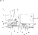
- the pump 10 comprises an inlet 11 supplied with water from the reservoir 5, an outlet 12 and a drive system 13 of liquid to pressurize and circulate the water from the inlet 11 to the outlet orifice 12.
- the liquid drive system 13 comprises a piston 14 and a coil 15 which extend along an axis ⁇ .
- the electric supply of the coil 15 by the control circuit 60 imparts to the piston 14 an alternating movement along the axis ⁇ .
- the pump 10 comprises a downstream conduit 20 which connects the liquid drive system 13 to the outlet orifice 12.
- the downstream conduit 20 comprises a rigid portion 21 bent, a flexible portion 22 and a damping device 30.
- the flexible portion 22 fluidically connects the rigid portion 21 bent to the damping device 30.
- the flexible portion 22 extends over a length equal to five centimeters.
- the rigid portion 21 comprises a duct appendix 23 intended to evacuate the overpressures generated in the pump 10.
- the damping device 30 has a generally cylindrical shape.
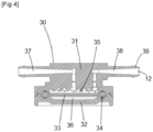
- the damping device comprises an upper body 31, a lower body 32 and a circular flexible membrane 33 provided with a peripheral edge 34.
- the flexible membrane 33 is arranged between the upper body 31 and the lower body 32 which hold the edge by pinching it. peripheral 34.
- the upper body 31 and the flexible membrane 33 define a damping cavity 35.
- the lower body 32 and the flexible membrane 33 define a closed cavity 36 filled with air.
- the upper body 31 includes an inlet channel 37 and an outlet channel 38.
- the inlet channel 37 fluidically connects the flexible portion 22 of the downstream conduit 20 to the damping cavity 35.
- the outlet channel 38 has one end free 39 which includes the outlet orifice 12.
- the outlet channel 38 fluidically connects the damping cavity 35 and the outlet orifice 12.
- the flexible membrane 33 is made of a material chosen from a silicone, a rubber or a thermoplastic elastomer. The pulsations generated by the piston 14 oscillating in the liquid which enters the damping chamber 35 are damped by the deformation of the flexible membrane 33 in the closed cavity 36 filled with air.
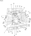
- the automatic coffee machine 1 comprises a flexible support 40 which comprises a housing 41 for receiving the damping device 30.
- the flexible support 40 is made of a material chosen from a silicone, a rubber or a thermoplastic elastomer.
- the receiving housing 41 comprises a bottom wall 42, a side wall 43 which extends upwards and an upper opening 45.
- the side wall 43 comprises two notches 44a, 44b for the passage of the inlet channel 37 and the channel outlet 38 of the upper body 31.
- the flexible support 40 comprises four pillars 46a, 46b, 46c, 46d which extend upwards in the extension of the side wall.
- the pillars 46a, 46b, 46c, 46d have upper faces 47a, 47b, 47c, 47d which are inscribed in a horizontal plane.
- Each pillar 46a, 46b, 46c, 46d comprises a material return 48a, 48b, 48c, 48d which extends radially, towards the inside of the receiving housing 41 to block the damping device 30 in position.
- the two notches 44a, 44b allow a deformation of the bottom wall 42 to separate the returns of material 48a, 48b, 48c, 48d and to allow the passage of the damping device 30 in the receiving housing 41.
- the damping device 30 is tightly mounted in the receiving housing 41, in particular at the side wall 43.
- the flexible support 40 has three feet 49a, 49b, 49c distributed equidistantly over its periphery.
- Each foot 49a, 49b, 49c comprises an annular portion 50a, 50b, 50c which extends vertically and which is connected to the flexible support 40.
- the base 3 of the frame 2 comprises three receiving elements 51a, 51b, 51c of the three legs 49a , 49b, 49c.
- Each receiving element 51a, 51b, 51c comprises a vertical cavity 52a, 52b, 52c, open upwards and of a shape complementary to the shape of each foot 49a, 49b, 49c.
- the three feet 49a, 49b, 49c are forcibly inserted into the three cavities 52a, 52b, 52c to position and hold the flexible support 40 on the base 3 of the frame 2.
- the frame 2 comprises a side box 55 for receiving the tray 6 for recovering the grind cakes.
- the side box 55 comprises a lower wall 56 which is arranged above the flexible support 40.
- the lower wall 56 extends in a plane slightly offset in height relative to the plane in which the upper faces 47a, 47b are inscribed, 47c, 47d of pillars 46a, 46b, 46c, 46d.
- the pump is a rotary vane pump whose drive system comprises a rotor provided with several blades which slide radially and ensure the transfer of the pumped fluid.
Landscapes
- Engineering & Computer Science (AREA)
- Food Science & Technology (AREA)
- Apparatus For Making Beverages (AREA)
- Tea And Coffee (AREA)
Abstract
Description
- La présente invention concerne le domaine technique général des machines à café automatiques, plus particulièrement des machines à café automatiques qui comportent une pompe de transfert de fluide générant des vibrations.
- Il est connu du document
EP2542128 une machine à café automatique comportant une pompe. La pompe comprend un orifice d'entrée, un orifice de sortie, un système d'entraînement de liquide pour mettre sous pression et faire circuler un liquide, notamment de l'eau, de l'orifice d'entrée vers l'orifice de sortie et un conduit aval reliant en communication fluidique le système d'entraînement à l'orifice de sortie de pompe. Le conduit aval comprend un dispositif amortisseur pour amortir les vibrations générées par le système d'entraînement dans le liquide sous pression qui circule vers l'orifice de sortie. Le conduit aval est formé par une portion rigide d'un seul tenant qui s'étend depuis le système d'entraînement jusqu'à l'orifice de sortie de pompe. - Cependant, le dispositif amortisseur peut générer également des vibrations qui sont transmises en retour à la pompe et au bâti de la machine par la portion rigide, ces vibrations créant des nuisances essentiellement sonores.
- De plus, le conduit aval rigide muni du dispositif d'amortissement forme sur la pompe une excroissance importante qui peut poser des problèmes d'agencement de la pompe à l'intérieur de la machine à café automatique.
- La présente invention vise à remédier à ces inconvénients.
- Le problème technique à la base de l'invention consiste à proposer une machine à café automatique comportant une pompe qui présente un fonctionnement avec des nuisances réduites, notamment des nuisances sonores et/ou vibratoires.
- Un autre but de l'invention est de proposer une machine à café automatique qui présente une conception compacte, simple et économique à mettre en œuvre.
- A cet effet, l'invention a pour objet une machine à café automatique comportant une pompe comprenant un orifice d'entrée, un orifice de sortie, un système d'entraînement de liquide pour mettre sous pression et faire circuler un liquide de l'orifice d'entrée vers l'orifice de sortie et un conduit aval reliant en communication fluidique le système d'entraînement à l'orifice de sortie de pompe, ledit conduit aval comprenant un dispositif amortisseur pour amortir les vibrations générées par le système d'entraînement dans le liquide sous pression qui circule vers l'orifice de sortie, caractérisée en ce que le conduit aval comporte une portion souple agencée entre le système d'entrainement et le dispositif amortisseur et en ce que le dispositif amortisseur est agencé dans un support souple.
- Par le dispositif amortisseur est agencé dans un support souple, on comprend que le support souple est dissocié de la pompe.
- Ainsi, la portion souple du conduit aval découple le dispositif amortisseur du système d'entraînement de la pompe. Les vibrations induites par le dispositif amortisseur sont amorties par le support souple. En conséquence, les nuisances, notamment sonores s'en trouvent réduites.
- De plus le support souple muni du dispositif amortisseur peut être positionné dans l'espace disponible dans la machine à café automatique et facilement relié au système d'entraînement de la pompe par le conduit souple.
- Avantageusement, la portion souple s'étend sur une longueur supérieure à deux centimètres.
- Une telle disposition permet de découpler efficacement le dispositif amortisseur du système d'entraînement de la pompe
- De préférence, la portion souple s'étend de manière rectiligne.
- Avantageusement, le dispositif amortisseur comporte un corps supérieur, un corps inférieur et une membrane souple, la membrane souple étant agencée entre le corps supérieur et le corps inférieur.
- De manière avantageuse, le corps supérieur et le membrane souple définissent une cavité d'amortissement munie d'un canal d'entrée et d'un canal de sortie et le corps inférieur et la membrane souple définissent une cavité fermée remplie d'air.
- De préférence, le support souple est réalisé en un matériau choisi parmi le support souple est réalisé en un matériau choisi parmi un silicone, un caoutchouc, ou un élastomère thermoplastique.
- De tels matériaux permettent de maintenir efficacement le dispositif amortisseur tout en filtrant les vibrations.
- Avantageusement, la machine à café automatique comporte un bâti, le support souple étant fixé sur le bâti.
- Ainsi, le support souple muni du dispositif amortisseur n'est pas fixé directement sur la pompe pour améliorer le découplage du dispositif amortisseur du système d'entraînement de la pompe
- De préférence, le support souple comporte un logement de réception du dispositif amortisseur et au moins deux pieds agencés latéralement au logement de réception et le bâti comporte un socle comprenant au moins deux éléments de réception, les au moins deux pieds étant engagés dans les au moins deux éléments de réception.
- Un tel agencement permet de loger le support dans un espace réduit.
- Avantageusement, le bâti comporte un boitier latéral, le boitier latéral comportant une paroi inférieure qui coiffe le support souple pour le maintenir sur le bâti.
- Une telle disposition permet une construction compacte de la machine à café automatique.
- De préférence, le logement de réception comporte une ouverture supérieure d'introduction du dispositif amortisseur.
- Ainsi, la paroi inférieure du boitier latéral maintient le dispositif amortisseur en place dans le logement de réception.
- De préférence, la pompe est une pompe électromagnétique et le système d'entraînement de liquide comporte un piston et une bobine.
- Une telle pompe est particulièrement économique.
- On comprendra mieux les buts, aspects et avantages de la présente invention, d'après la description donnée ci-après d'un mode particulier de réalisation de l'invention présenté à titre d'exemple non limitatif, en se référant aux dessins annexés dans lesquels :
- La
figure 1 est une vue en perspective d'une machine à café automatique comportant une pompe selon un mode particulier de réalisation de l'invention. - La
figure 2 est une vue en perspective écorchée suivant une direction II de la machine à café automatique illustrée sur lafigure 1 , une partie du bâti étant retirée. - La
figure 3 est une vue en perspective éclatée suivant une direction III du bâti, du support souple et du dispositif amortisseur de la machine à café automatique illustrée sur lafigure 1 . - La
figure 4 est une vue en coupe suivant le plan de coupe vertical suivant la ligne IV-IV du dispositif amortisseur de machine à café automatique de lafigure 1 . - Seuls les éléments nécessaires à la compréhension de l'invention ont été représentés. Pour faciliter la lecture des dessins, les mêmes éléments portent les mêmes références d'une figure à l'autre.
- On notera que dans ce document, les termes "horizontal", "vertical", "inférieur", "supérieur", "haut", "bas", "avant", "arrière", "longitudinal", "transversal", employés pour décrire la machine à café automatique font référence à cette machine reposant sur un plan de travail, en situation d'usage.
- Dans l'exemple de réalisation représenté aux
figures 1 à 4 , une machine à café automatique 1 comporte un bâti 2 muni d'un socle 3 destiné à reposer sur un plan de travail. La machine à café automatique 1 comporte un réservoir 5 formant une alimentation en eau froide, une pompe 10 électromagnétique (Fig. 2 ) et un groupe d'infusion (non représentés sur les figures) muni d'une chambre d'infusion alimentée en mouture de café par un broyeur à grains de café. Le groupe d'infusion comporte un piston presseur comprimant la mouture dans la chambre d'infusion pour former une galette de mouture. Le groupe d'infusion comporte un dispositif d'expulsion de la galette de mouture dans un bac 6 de récupération des galettes de mouture. Un tel groupe d'infusion a été décrit plus en détail dans le brevetEP1827182 . La machine à café automatique 1 comporte une chaudière (non représentée sur les figures) qui permet de produire de l'eau chaude et/ou de la vapeur. - La machine à café automatique 1 comporte une tête de distribution 7 du café (
Fig.1 ) qui est agencée sur le bâti 2 et qui comprend des sorties de café 9 reliées à la chambre d'infusion. La tête de distribution 7 est agencée au-dessus d'un repose tasse 8. Le repose tasse 8 s'étend dans le prolongement de du socle 3. La tête de distribution 7 est montée mobile en translation verticale pour permettre à un utilisateur d'ajuster la position des sorties de café 9 à la hauteur de la tasse. La machine à café automatique 1 comporte un bac à grains de café 4 agencé au-dessus du broyeur. La machine à café automatique 1 comporte un circuit de commande 60 pour gérer la réalisation d'une boisson à partir des instructions données par un utilisateur. - La pompe 10 électromagnétique alimente en eau un distributeur hydraulique (non représentés sur les figures) qui est piloté par le circuit de commande 60 pour répartir l'eau vers les différents organes de la machine à café automatique 1. La pompe 10 est reliée au bâti 2 par des dispositifs de connexion mécaniques amortissants (non illustrés sur les figures). Conformément à la
figure 2 , la pompe 10 comporte un orifice d'entrée 11 alimenté en eau par le réservoir 5, un orifice de sortie 12 et un système d'entraînement 13 de liquide pour mettre sous pression et faire circuler l'eau de l'orifice d'entrée 11 vers l'orifice de sortie 12. Le système d'entrainement 13 de liquide comporte un piston 14 et une bobine 15 qui s'étendent selon un axe Δ. L'alimentation électrique de la bobine 15 par le circuit de commande 60 imprime au piston 14 un mouvement alternatif selon l'axe Δ. La pompe 10 comporte un conduit aval 20 qui relie le système d'entrainement 13 de liquide à l'orifice de sortie 12. Le conduit aval 20 comporte une portion rigide 21 coudée, une portion souple 22 et un dispositif amortisseur 30. La portion souple 22 relie fluidiquement la portion rigide 21 coudée au dispositif amortisseur 30. la portion souple 22 s'étend sur une longueur égale à cinq centimètres. La portion rigide 21 comporte un conduit annexe 23 destiné à évacuer les surpressions générées dans la pompe 10. - Conformément aux
figures 3 et4 , le dispositif amortisseur 30 présente une forme générale cylindrique. Le dispositif amortisseur comporte un corps supérieur 31, un corps inférieur 32 et une membrane souple 33 circulaire munie d'une bordure périphérique 34. La membrane souple 33 est agencée entre le corps supérieur 31 et le corps inférieur 32 qui maintiennent en la pinçant la bordure périphérique 34. Le corps supérieur 31 et la membrane souple 33 définissent une cavité d'amortissement 35. Le corps inférieur 32 et la membrane souple 33 définissent une cavité fermée 36 remplie d'air. Le corps supérieur 31 comporte un canal d'entrée 37 et un canal de sortie 38. Le canal d'entrée 37 relie fluidiquement la portion souple 22 du conduit aval 20 à la cavité d'amortissement 35. Le canal de sortie 38 comporte une extrémité libre 39 qui comprend l'orifice de sortie 12. Le canal de sortie 38 relie fluidiquement la cavité d'amortissement 35 et l'orifice de sortie 12. La membrane souple 33 est réalisée en un matériau choisi parmi un silicone, un caoutchouc ou un élastomère thermoplastique. Les pulsations générées par le piston 14 oscillant dans le liquide qui entre dans la chambre d'amortissement 35 sont amorties par la déformation de la membrane souple 33 dans la cavité fermée 36 remplie d'air. - Conformément à la
figure 3 , la machine à café automatique 1 comporte un support souple 40 qui comprend un logement de réception 41 du dispositif amortisseur 30. Le support souple 40 est réalisé en un matériau choisi parmi un silicone, un caoutchouc ou un élastomère thermoplastique. Le logement de réception 41 comporte une paroi de fond 42, une paroi latérale 43 qui s'étend vers le haut et une ouverture supérieure 45. La paroi latérale 43 comporte deux échancrures 44a, 44b de passage du canal d'entrée 37 et du canal de sortie 38 du corps supérieur 31. Le support souple 40 comporte quatre piliers 46a, 46b, 46c, 46d qui s'étendent vers le haut dans le prolongement de la paroi latérale. Les piliers 46a, 46b, 46c, 46d comportent des faces supérieures 47a, 47b, 47c, 47d qui s'inscrivent dans un plan horizontal. Chaque pilier 46a, 46b, 46c, 46d comporte un retour de matière 48a, 48b, 48c, 48d qui s'étend radialement, vers l'intérieur du logement de réception 41 pour bloquer en position le dispositif amortisseur 30. Lors du montage, les deux échancrures 44a, 44b permettent une déformation de la paroi de fond 42 pour écarter les retours de matière 48a, 48b, 48c, 48d et autoriser le passage du dispositif amortisseur 30 dans le logement de réception 41. Ainsi, le dispositif amortisseur 30 est monté serré dans le logement de réception 41, notamment au niveau de la paroi latérale 43. - Tel que visible à la
figure 3 , le support souple 40 comporte trois pieds 49a, 49b, 49c répartis de manière équidistante sur sa périphérie. Chaque pied 49a, 49b, 49c comporte une portion annulaire 50a, 50b, 50c qui s'étend verticalement et qui est reliée au support souple 40. Le socle 3 du bâti 2 comporte trois éléments de réception 51a, 51b, 51c des trois pieds 49a, 49b, 49c. Chaque élément de réception 51a, 51b, 51c comporte une cavité 52a, 52b, 52c verticale, ouverte vers le haut et de forme complémentaire à la forme de chaque pied 49a, 49b, 49c. Les trois pieds 49a, 49b, 49c sont insérés en force dans les trois cavités 52a, 52b, 52c pour positionner et maintenir le support souple 40 sur le socle 3 du bâti 2. - Conformément à la
figure 2 , le bâti 2 comporte un boitier latéral 55 de réception du bac 6 de récupération des galettes de mouture. Le boitier latéral 55 comprend une paroi inférieure 56 qui est agencée au-dessus du support souple 40. La paroi inférieure 56 s'étend dans un plan légèrement décalé en hauteur par rapport au plan dans lequel s'inscrivent les faces supérieures 47a, 47b, 47c, 47d des piliers 46a, 46b, 46c, 46d. - Bien entendu, l'invention n'est nullement limitée au mode de réalisation décrit et illustré qui n'a été donné qu'à titre d'exemple. Des modifications restent possibles, notamment du point de vue de la constitution des divers éléments ou par substitution d'équivalents techniques, sans sortir pour autant du domaine de protection de l'invention.
- Ainsi, dans une variante de réalisation non illustrée, la pompe est une pompe rotative à palettes dont le système d'entrainement comporte un rotor muni de plusieurs lames qui coulissent radialement et assurent le transfert du fluide pompé.
Claims (10)
- Machine à café automatique (1) comportant une pompe (10) comprenant un orifice d'entrée (11), un orifice de sortie (12), un système d'entraînement (13) de liquide pour mettre sous pression et faire circuler un liquide de l'orifice d'entrée (11) vers l'orifice de sortie (12) et un conduit aval (20) reliant en communication fluidique le système d'entraînement (13) à l'orifice de sortie (12) de pompe (10), ledit conduit aval (20) comprenant un dispositif amortisseur (30) pour amortir les vibrations générées par le système d'entraînement (13) dans le liquide sous pression qui circule vers l'orifice de sortie (12), caractérisée en ce que le conduit aval (20) comporte une portion souple (22) agencée entre le système d'entrainement (13) et le dispositif amortisseur (30) et en ce que le dispositif amortisseur (30) est agencé dans un support souple (40).
- Machine à café automatique (1) selon la revendication 1, caractérisée en ce que la portion souple (22) s'étend sur une longueur supérieure à deux centimètres.
- Machine à café automatique (1) selon l'une quelconque des revendications 1 à 2, caractérisée en ce que la portion souple (22) s'étend de manière rectiligne.
- Machine à café automatique (1) selon l'une quelconque des revendications 1 à 3, caractérisée en ce que le dispositif amortisseur (30) comporte un corps supérieur (31), un corps inférieur (32) et une membrane souple (33), la membrane souple (33) étant agencée entre le corps supérieur (31) et le corps inférieur (32).
- Machine à café automatique (1) selon l'une quelconque des revendications 1 à 4, caractérisée en ce que le support souple (40) est réalisé en un matériau choisi parmi un silicone, un caoutchouc ou un élastomère thermoplastique.
- Machine à café automatique (1) selon l'une quelconque des revendications 1 à 5, caractérisée en ce qu'elle comporte un bâti (2), le support souple (40) étant fixé sur le bâti (2).
- Machine à café automatique (1) selon la revendication 6, caractérisée en ce que le support souple (40) comporte un logement de réception (41) du dispositif amortisseur (30) et au moins deux pieds (49a, 49b, 49c) agencés latéralement au logement de réception (41) et en ce que le bâti (2) comporte un socle (3) comprenant au moins deux éléments de réception (51a, 51b, 51c), les au moins deux pieds (49a, 49b, 49c) étant engagés dans les au moins deux éléments de réception (51a, 51b, 51c).
- Machine à café automatique (1) selon la revendication 7, caractérisée en ce que le bâti (2) comporte un boitier latéral (55), le boitier latéral (55) comportant une paroi inférieure (56) qui coiffe le support souple (40) pour le maintenir sur le bâti (2).
- Machine à café automatique (1) selon l'une quelconque des revendications 7 à 8, caractérisée en ce que le logement de réception (41) comporte une ouverture supérieure (45) d'introduction du dispositif amortisseur (30).
- Machine à café automatique (1) selon l'une quelconque des revendications 1 à 9, caractérisée en ce que la pompe (10) est une pompe électromagnétique et le système d'entraînement (13) de liquide comporte un piston (14) et une bobine (15).
Applications Claiming Priority (1)
| Application Number | Priority Date | Filing Date | Title |
|---|---|---|---|
| FR2110632A FR3127870B1 (fr) | 2021-10-07 | 2021-10-07 | Machine a cafe automatique munie d’une pompe avec un dispositif d’amortissement ameliore |
Publications (3)
| Publication Number | Publication Date |
|---|---|
| EP4162847A1 true EP4162847A1 (fr) | 2023-04-12 |
| EP4162847B1 EP4162847B1 (fr) | 2024-07-17 |
| EP4162847C0 EP4162847C0 (fr) | 2024-07-17 |
Family
ID=78333001
Family Applications (1)
| Application Number | Title | Priority Date | Filing Date |
|---|---|---|---|
| EP22198538.5A Active EP4162847B1 (fr) | 2021-10-07 | 2022-09-28 | Machine a café automatique munie d'une pompe avec un dispositif d'amortissement amelioré |
Country Status (3)
| Country | Link |
|---|---|
| EP (1) | EP4162847B1 (fr) |
| CN (1) | CN115944210A (fr) |
| FR (1) | FR3127870B1 (fr) |
Citations (6)
| Publication number | Priority date | Publication date | Assignee | Title |
|---|---|---|---|---|
| EP1827182A1 (fr) | 2004-12-06 | 2007-09-05 | Seb Sa | Distributeur automatique de boissons infusees comportant un dispositif d'expulsion de produit infuse |
| WO2011107574A2 (fr) * | 2010-03-05 | 2011-09-09 | Nestec S.A. | Réduction de problèmes de pompe |
| WO2013011475A2 (fr) * | 2011-07-19 | 2013-01-24 | Koninklijke Philips Electronics N.V. | Appareil ménager comprenant un actionneur |
| DE202014010335U1 (de) * | 2013-11-21 | 2015-04-20 | Eugster/Frismag Ag | Pumpenanordnung sowie Getränkezubereitungsvorrichtung |
| US20170099982A1 (en) * | 2015-10-08 | 2017-04-13 | Flow Control LLC | Solenoid pump mounting method |
| CN111631602A (zh) * | 2020-06-30 | 2020-09-08 | 深圳市西啡科技有限公司 | 一种核心模组及咖啡机或饮品机 |
-
2021
- 2021-10-07 FR FR2110632A patent/FR3127870B1/fr active Active
-
2022
- 2022-09-28 EP EP22198538.5A patent/EP4162847B1/fr active Active
- 2022-09-28 CN CN202211189183.7A patent/CN115944210A/zh active Pending
Patent Citations (7)
| Publication number | Priority date | Publication date | Assignee | Title |
|---|---|---|---|---|
| EP1827182A1 (fr) | 2004-12-06 | 2007-09-05 | Seb Sa | Distributeur automatique de boissons infusees comportant un dispositif d'expulsion de produit infuse |
| WO2011107574A2 (fr) * | 2010-03-05 | 2011-09-09 | Nestec S.A. | Réduction de problèmes de pompe |
| EP2542128A2 (fr) | 2010-03-05 | 2013-01-09 | Nestec S.A. | Réduction de problèmes de pompe |
| WO2013011475A2 (fr) * | 2011-07-19 | 2013-01-24 | Koninklijke Philips Electronics N.V. | Appareil ménager comprenant un actionneur |
| DE202014010335U1 (de) * | 2013-11-21 | 2015-04-20 | Eugster/Frismag Ag | Pumpenanordnung sowie Getränkezubereitungsvorrichtung |
| US20170099982A1 (en) * | 2015-10-08 | 2017-04-13 | Flow Control LLC | Solenoid pump mounting method |
| CN111631602A (zh) * | 2020-06-30 | 2020-09-08 | 深圳市西啡科技有限公司 | 一种核心模组及咖啡机或饮品机 |
Also Published As
| Publication number | Publication date |
|---|---|
| FR3127870B1 (fr) | 2023-10-06 |
| EP4162847B1 (fr) | 2024-07-17 |
| EP4162847C0 (fr) | 2024-07-17 |
| FR3127870A1 (fr) | 2023-04-14 |
| CN115944210A (zh) | 2023-04-11 |
Similar Documents
| Publication | Publication Date | Title |
|---|---|---|
| EP2922447B1 (fr) | Dispositif de preparation de boisson par infusion de dosette avec berceau pivotant | |
| FR2947442A3 (fr) | Kit destine a ameliorer les proprietes d'etancheite d'une capsule remplissable | |
| EP1583446B1 (fr) | Dispositif et machine pour l'extraction d'une substance pour la production de boisson | |
| EP0452214A1 (fr) | Moulin à café et machine à café équipée d'un tel moulin | |
| EP0919171A1 (fr) | Porte-filtre pour cafetière du type expresso | |
| FR3065865B1 (fr) | Machine de preparation de boissons, dont des boissons lactees, munie d'une douchette et d'un support de dosette | |
| EP2511417B1 (fr) | Appareil électroménager de repassage comportant un boîtier comprenant un réservoir et une pompe alimentée en liquide par le réservoir | |
| EP4205607A1 (fr) | Machine a cafe automatique munie d'un bac de recuperation de galettes de mouture ameliore | |
| EP4162847B1 (fr) | Machine a café automatique munie d'une pompe avec un dispositif d'amortissement amelioré | |
| FR2804002A1 (fr) | Groupe pour la fabrication de boissons par infusion et machine l'integrant | |
| FR2713905A1 (fr) | Machine automatique pour la préparation d'infusions de boissons chaudes. | |
| EP2018955A1 (fr) | Cuve de pressoir | |
| KR101553517B1 (ko) | 소음 및 진동 발생이 억제되는 커피머신용 진동펌프 | |
| EP1628883A2 (fr) | Distributeur de produit fluide | |
| EP0622040B1 (fr) | Machine à café électrique | |
| WO2011023895A1 (fr) | Ensemble et procede de conditionnement sous vide | |
| EP0919170B1 (fr) | Porte-filtre pour cafétière du type expresso | |
| EP2378930B1 (fr) | Dispositif de filtration pour des infusions et appareil de confection d'infusions équipé d'un tel dispositif | |
| EP2937460B1 (fr) | Appareil électroménager de repassage comportant un réservoir et une pompe reliée au réservoir | |
| FR3065866A1 (fr) | Machine de preparation de boissons munie d'un support de recipient escamotable | |
| FR2886830A1 (fr) | Porte-filtre pour mouture de cafe et machine a cafe comprenant un tel porte-filtre | |
| EP4302658A1 (fr) | Procede de nettoyage optimise d'une chambre d'infusion d'une machine a cafe | |
| WO1995029015A1 (fr) | Dispositif de reglage du volume d'une chambre de pompe d'une pompe a precompression | |
| EP1578652A1 (fr) | Dispositif de commande de frein a ma tre-cylindre | |
| FR2833825A1 (fr) | Porte-filtre a cafe |
Legal Events
| Date | Code | Title | Description |
|---|---|---|---|
| PUAI | Public reference made under article 153(3) epc to a published international application that has entered the european phase |
Free format text: ORIGINAL CODE: 0009012 |
|
| STAA | Information on the status of an ep patent application or granted ep patent |
Free format text: STATUS: THE APPLICATION HAS BEEN PUBLISHED |
|
| AK | Designated contracting states |
Kind code of ref document: A1 Designated state(s): AL AT BE BG CH CY CZ DE DK EE ES FI FR GB GR HR HU IE IS IT LI LT LU LV MC MK MT NL NO PL PT RO RS SE SI SK SM TR |
|
| STAA | Information on the status of an ep patent application or granted ep patent |
Free format text: STATUS: REQUEST FOR EXAMINATION WAS MADE |
|
| 17P | Request for examination filed |
Effective date: 20230913 |
|
| RBV | Designated contracting states (corrected) |
Designated state(s): AL AT BE BG CH CY CZ DE DK EE ES FI FR GB GR HR HU IE IS IT LI LT LU LV MC MK MT NL NO PL PT RO RS SE SI SK SM TR |
|
| GRAP | Despatch of communication of intention to grant a patent |
Free format text: ORIGINAL CODE: EPIDOSNIGR1 |
|
| STAA | Information on the status of an ep patent application or granted ep patent |
Free format text: STATUS: GRANT OF PATENT IS INTENDED |
|
| RIC1 | Information provided on ipc code assigned before grant |
Ipc: A47J 31/44 20060101ALI20240112BHEP Ipc: A47J 31/46 20060101AFI20240112BHEP |
|
| INTG | Intention to grant announced |
Effective date: 20240213 |
|
| GRAS | Grant fee paid |
Free format text: ORIGINAL CODE: EPIDOSNIGR3 |
|
| GRAA | (expected) grant |
Free format text: ORIGINAL CODE: 0009210 |
|
| STAA | Information on the status of an ep patent application or granted ep patent |
Free format text: STATUS: THE PATENT HAS BEEN GRANTED |
|
| AK | Designated contracting states |
Kind code of ref document: B1 Designated state(s): AL AT BE BG CH CY CZ DE DK EE ES FI FR GB GR HR HU IE IS IT LI LT LU LV MC MK MT NL NO PL PT RO RS SE SI SK SM TR |
|
| REG | Reference to a national code |
Ref country code: CH Ref legal event code: EP |
|
| REG | Reference to a national code |
Ref country code: DE Ref legal event code: R096 Ref document number: 602022004606 Country of ref document: DE |
|
| REG | Reference to a national code |
Ref country code: IE Ref legal event code: FG4D Free format text: LANGUAGE OF EP DOCUMENT: FRENCH |
|
| U01 | Request for unitary effect filed |
Effective date: 20240717 |
|
| U07 | Unitary effect registered |
Designated state(s): AT BE BG DE DK EE FI FR IT LT LU LV MT NL PT RO SE SI Effective date: 20240902 |
|
| U20 | Renewal fee for the european patent with unitary effect paid |
Year of fee payment: 3 Effective date: 20240827 |
|
| PG25 | Lapsed in a contracting state [announced via postgrant information from national office to epo] |
Ref country code: NO Free format text: LAPSE BECAUSE OF FAILURE TO SUBMIT A TRANSLATION OF THE DESCRIPTION OR TO PAY THE FEE WITHIN THE PRESCRIBED TIME-LIMIT Effective date: 20241017 |
|
| PG25 | Lapsed in a contracting state [announced via postgrant information from national office to epo] |
Ref country code: GR Free format text: LAPSE BECAUSE OF FAILURE TO SUBMIT A TRANSLATION OF THE DESCRIPTION OR TO PAY THE FEE WITHIN THE PRESCRIBED TIME-LIMIT Effective date: 20241018 Ref country code: PL Free format text: LAPSE BECAUSE OF FAILURE TO SUBMIT A TRANSLATION OF THE DESCRIPTION OR TO PAY THE FEE WITHIN THE PRESCRIBED TIME-LIMIT Effective date: 20240717 |
|
| PG25 | Lapsed in a contracting state [announced via postgrant information from national office to epo] |
Ref country code: IS Free format text: LAPSE BECAUSE OF FAILURE TO SUBMIT A TRANSLATION OF THE DESCRIPTION OR TO PAY THE FEE WITHIN THE PRESCRIBED TIME-LIMIT Effective date: 20241117 |
|
| PG25 | Lapsed in a contracting state [announced via postgrant information from national office to epo] |
Ref country code: HR Free format text: LAPSE BECAUSE OF FAILURE TO SUBMIT A TRANSLATION OF THE DESCRIPTION OR TO PAY THE FEE WITHIN THE PRESCRIBED TIME-LIMIT Effective date: 20240717 |
|
| PG25 | Lapsed in a contracting state [announced via postgrant information from national office to epo] |
Ref country code: RS Free format text: LAPSE BECAUSE OF FAILURE TO SUBMIT A TRANSLATION OF THE DESCRIPTION OR TO PAY THE FEE WITHIN THE PRESCRIBED TIME-LIMIT Effective date: 20241017 Ref country code: ES Free format text: LAPSE BECAUSE OF FAILURE TO SUBMIT A TRANSLATION OF THE DESCRIPTION OR TO PAY THE FEE WITHIN THE PRESCRIBED TIME-LIMIT Effective date: 20240717 |
|
| PG25 | Lapsed in a contracting state [announced via postgrant information from national office to epo] |
Ref country code: RS Free format text: LAPSE BECAUSE OF FAILURE TO SUBMIT A TRANSLATION OF THE DESCRIPTION OR TO PAY THE FEE WITHIN THE PRESCRIBED TIME-LIMIT Effective date: 20241017 Ref country code: PL Free format text: LAPSE BECAUSE OF FAILURE TO SUBMIT A TRANSLATION OF THE DESCRIPTION OR TO PAY THE FEE WITHIN THE PRESCRIBED TIME-LIMIT Effective date: 20240717 Ref country code: NO Free format text: LAPSE BECAUSE OF FAILURE TO SUBMIT A TRANSLATION OF THE DESCRIPTION OR TO PAY THE FEE WITHIN THE PRESCRIBED TIME-LIMIT Effective date: 20241017 Ref country code: IS Free format text: LAPSE BECAUSE OF FAILURE TO SUBMIT A TRANSLATION OF THE DESCRIPTION OR TO PAY THE FEE WITHIN THE PRESCRIBED TIME-LIMIT Effective date: 20241117 Ref country code: HR Free format text: LAPSE BECAUSE OF FAILURE TO SUBMIT A TRANSLATION OF THE DESCRIPTION OR TO PAY THE FEE WITHIN THE PRESCRIBED TIME-LIMIT Effective date: 20240717 Ref country code: GR Free format text: LAPSE BECAUSE OF FAILURE TO SUBMIT A TRANSLATION OF THE DESCRIPTION OR TO PAY THE FEE WITHIN THE PRESCRIBED TIME-LIMIT Effective date: 20241018 Ref country code: ES Free format text: LAPSE BECAUSE OF FAILURE TO SUBMIT A TRANSLATION OF THE DESCRIPTION OR TO PAY THE FEE WITHIN THE PRESCRIBED TIME-LIMIT Effective date: 20240717 |
|
| PG25 | Lapsed in a contracting state [announced via postgrant information from national office to epo] |
Ref country code: SM Free format text: LAPSE BECAUSE OF FAILURE TO SUBMIT A TRANSLATION OF THE DESCRIPTION OR TO PAY THE FEE WITHIN THE PRESCRIBED TIME-LIMIT Effective date: 20240717 |
|
| PG25 | Lapsed in a contracting state [announced via postgrant information from national office to epo] |
Ref country code: MC Free format text: LAPSE BECAUSE OF FAILURE TO SUBMIT A TRANSLATION OF THE DESCRIPTION OR TO PAY THE FEE WITHIN THE PRESCRIBED TIME-LIMIT Effective date: 20240717 |
|
| PG25 | Lapsed in a contracting state [announced via postgrant information from national office to epo] |
Ref country code: CZ Free format text: LAPSE BECAUSE OF FAILURE TO SUBMIT A TRANSLATION OF THE DESCRIPTION OR TO PAY THE FEE WITHIN THE PRESCRIBED TIME-LIMIT Effective date: 20240717 |
|
| PG25 | Lapsed in a contracting state [announced via postgrant information from national office to epo] |
Ref country code: SK Free format text: LAPSE BECAUSE OF FAILURE TO SUBMIT A TRANSLATION OF THE DESCRIPTION OR TO PAY THE FEE WITHIN THE PRESCRIBED TIME-LIMIT Effective date: 20240717 |
|
| PLBE | No opposition filed within time limit |
Free format text: ORIGINAL CODE: 0009261 |
|
| STAA | Information on the status of an ep patent application or granted ep patent |
Free format text: STATUS: NO OPPOSITION FILED WITHIN TIME LIMIT |
|
| 26N | No opposition filed |
Effective date: 20250422 |
|
| PG25 | Lapsed in a contracting state [announced via postgrant information from national office to epo] |
Ref country code: IE Free format text: LAPSE BECAUSE OF NON-PAYMENT OF DUE FEES Effective date: 20240928 |
|
| U20 | Renewal fee for the european patent with unitary effect paid |
Year of fee payment: 4 Effective date: 20250826 |
|
| PG25 | Lapsed in a contracting state [announced via postgrant information from national office to epo] |
Ref country code: CY Free format text: LAPSE BECAUSE OF FAILURE TO SUBMIT A TRANSLATION OF THE DESCRIPTION OR TO PAY THE FEE WITHIN THE PRESCRIBED TIME-LIMIT; INVALID AB INITIO Effective date: 20220928 |
|
| PG25 | Lapsed in a contracting state [announced via postgrant information from national office to epo] |
Ref country code: HU Free format text: LAPSE BECAUSE OF FAILURE TO SUBMIT A TRANSLATION OF THE DESCRIPTION OR TO PAY THE FEE WITHIN THE PRESCRIBED TIME-LIMIT; INVALID AB INITIO Effective date: 20220928 |
|
| REG | Reference to a national code |
Ref country code: CH Ref legal event code: H13 Free format text: ST27 STATUS EVENT CODE: U-0-0-H10-H13 (AS PROVIDED BY THE NATIONAL OFFICE) Effective date: 20260425 |