EP4161171A1 - Amélioration de la synchronisation - Google Patents
Amélioration de la synchronisation Download PDFInfo
- Publication number
- EP4161171A1 EP4161171A1 EP22193804.6A EP22193804A EP4161171A1 EP 4161171 A1 EP4161171 A1 EP 4161171A1 EP 22193804 A EP22193804 A EP 22193804A EP 4161171 A1 EP4161171 A1 EP 4161171A1
- Authority
- EP
- European Patent Office
- Prior art keywords
- synchronization mode
- signal
- synchronization
- downlink
- timing
- Prior art date
- Legal status (The legal status is an assumption and is not a legal conclusion. Google has not performed a legal analysis and makes no representation as to the accuracy of the status listed.)
- Pending
Links
- 230000009849 deactivation Effects 0.000 claims abstract description 32
- 230000004913 activation Effects 0.000 claims abstract description 26
- 230000003213 activating effect Effects 0.000 claims abstract description 9
- 230000005540 biological transmission Effects 0.000 claims description 50
- 238000005070 sampling Methods 0.000 claims description 33
- 238000001514 detection method Methods 0.000 claims description 19
- 238000000034 method Methods 0.000 abstract description 61
- 238000004891 communication Methods 0.000 description 32
- 238000004590 computer program Methods 0.000 description 30
- 230000008569 process Effects 0.000 description 17
- 238000005516 engineering process Methods 0.000 description 15
- 230000011664 signaling Effects 0.000 description 14
- 230000006870 function Effects 0.000 description 12
- 230000007246 mechanism Effects 0.000 description 10
- 238000012545 processing Methods 0.000 description 7
- 238000007726 management method Methods 0.000 description 6
- 230000006855 networking Effects 0.000 description 6
- 230000001413 cellular effect Effects 0.000 description 5
- 238000013500 data storage Methods 0.000 description 5
- 230000008901 benefit Effects 0.000 description 4
- 238000010586 diagram Methods 0.000 description 4
- 230000008054 signal transmission Effects 0.000 description 3
- 238000001228 spectrum Methods 0.000 description 3
- 101100411667 Arabidopsis thaliana RAN4 gene Proteins 0.000 description 2
- 101150069124 RAN1 gene Proteins 0.000 description 2
- 101100355633 Salmo salar ran gene Proteins 0.000 description 2
- 230000003190 augmentative effect Effects 0.000 description 2
- 230000009286 beneficial effect Effects 0.000 description 2
- 230000010267 cellular communication Effects 0.000 description 2
- 230000008859 change Effects 0.000 description 2
- 230000003247 decreasing effect Effects 0.000 description 2
- 230000003111 delayed effect Effects 0.000 description 2
- 230000007774 longterm Effects 0.000 description 2
- 238000005259 measurement Methods 0.000 description 2
- 238000010295 mobile communication Methods 0.000 description 2
- 230000003287 optical effect Effects 0.000 description 2
- 230000004044 response Effects 0.000 description 2
- 239000004065 semiconductor Substances 0.000 description 2
- 238000010561 standard procedure Methods 0.000 description 2
- WYWHKKSPHMUBEB-UHFFFAOYSA-N 6-Mercaptoguanine Natural products N1C(N)=NC(=S)C2=C1N=CN2 WYWHKKSPHMUBEB-UHFFFAOYSA-N 0.000 description 1
- 101100335572 Escherichia coli (strain K12) ftsN gene Proteins 0.000 description 1
- 101150084062 RAN gene Proteins 0.000 description 1
- 230000006978 adaptation Effects 0.000 description 1
- 238000004458 analytical method Methods 0.000 description 1
- 230000003466 anti-cipated effect Effects 0.000 description 1
- 238000013459 approach Methods 0.000 description 1
- 238000003491 array Methods 0.000 description 1
- 238000013475 authorization Methods 0.000 description 1
- 230000002567 autonomic effect Effects 0.000 description 1
- 230000006399 behavior Effects 0.000 description 1
- 238000004364 calculation method Methods 0.000 description 1
- 230000000295 complement effect Effects 0.000 description 1
- 230000001419 dependent effect Effects 0.000 description 1
- 238000011156 evaluation Methods 0.000 description 1
- 238000007519 figuring Methods 0.000 description 1
- 238000001914 filtration Methods 0.000 description 1
- 230000014509 gene expression Effects 0.000 description 1
- 230000007274 generation of a signal involved in cell-cell signaling Effects 0.000 description 1
- 238000007689 inspection Methods 0.000 description 1
- 101150106977 msgA gene Proteins 0.000 description 1
- 238000004088 simulation Methods 0.000 description 1
- 238000001356 surgical procedure Methods 0.000 description 1
- 235000019527 sweetened beverage Nutrition 0.000 description 1
- 229940095374 tabloid Drugs 0.000 description 1
- 238000012360 testing method Methods 0.000 description 1
- 238000012546 transfer Methods 0.000 description 1
- 230000001960 triggered effect Effects 0.000 description 1
Images


Classifications
-
- H—ELECTRICITY
- H04—ELECTRIC COMMUNICATION TECHNIQUE
- H04W—WIRELESS COMMUNICATION NETWORKS
- H04W56/00—Synchronisation arrangements
- H04W56/004—Synchronisation arrangements compensating for timing error of reception due to propagation delay
- H04W56/0045—Synchronisation arrangements compensating for timing error of reception due to propagation delay compensating for timing error by altering transmission time
-
- H—ELECTRICITY
- H04—ELECTRIC COMMUNICATION TECHNIQUE
- H04W—WIRELESS COMMUNICATION NETWORKS
- H04W52/00—Power management, e.g. TPC [Transmission Power Control], power saving or power classes
- H04W52/02—Power saving arrangements
- H04W52/0209—Power saving arrangements in terminal devices
- H04W52/0225—Power saving arrangements in terminal devices using monitoring of external events, e.g. the presence of a signal
- H04W52/0229—Power saving arrangements in terminal devices using monitoring of external events, e.g. the presence of a signal where the received signal is a wanted signal
Definitions
- Various example embodiments relate generally to synchronization, and for example to reducing power consumption of a user equipment while still obtaining improved synchronization.
- Network synchronization is important for optimal radio network performance.
- Accurate and reliable time synchronization in the network comprises for example that a base station and a user equipment share a common understanding of a clock time. Finding a balance between accuracy of timing and costs (e.g. power consumption) of obtaining the timing is required.
- the phrases “at least one of A or B”, “at least one of A and B", “A and/or B” means (A), (B), or (A and B).
- the phrases “A or B” and “A and/or B” means (A), (B), or (A and B).
- the phrase “A, B, and/or C” means (A), (B), (C), (A and B), (A and C), (B and C), or (A, B, and C).
- Embodiments described may be implemented in a radio system, such as one comprising at least one of the following radio access technologies (RATs): Worldwide In-teroperability for Micro-wave Access (WiMAX), Global System for Mobile communications (GSM, 2G), GSM EDGE radio access Network (GERAN), General Packet Radio Service (GRPS), Universal Mobile Telecommunication System (UMTS, 3G) based on basic wide-band-code division multiple access (W-CDMA), high-speed packet access (HSPA), Long Term Evolution (LTE), LTE-Advanced, and enhanced LTE (eLTE).
- Term 'eLTE' here denotes the LTE evolution that connects to a 5G core.
- LTE is also known as evolved UMTS terrestrial radio access (EUTRA) or as evolved UMTS terrestrial radio access network (EUTRAN).
- a term “resource” may refer to radio resources, such as a physical resource block (PRB), a radio frame, a subframe, a time slot, a subband, a frequency region, a subcarrier, a beam, etc.
- PRB physical resource block
- transmission and/or “reception” may refer to wirelessly transmitting and/or receiving via a wireless propagation channel on radio resources
- the embodiments are not, however, restricted to the systems/RATs given as an example but a person skilled in the art may apply the solution to other communication systems provided with necessary properties.
- a suitable communications system is the 5G system.
- the 3GPP solution to 5G is referred to as New Radio (NR).
- 5G has been envisaged to use multiple-input-multiple-output (MIMO) multi-antenna transmission techniques, more base stations or nodes than the current network deployments of LTE (a so-called small cell concept), including macro sites operating in co-operation with smaller local area access nodes and perhaps also employing a variety of radio technologies for better coverage and enhanced data rates.
- MIMO multiple-input-multiple-output
- 5G will likely be comprised of more than one radio access technology / radio access network (RAT/RAN), each optimized for certain use cases and/or spectrum.
- 5G mobile communications may have a wider range of use cases and related applications including video streaming, augmented reality, different ways of data sharing and various forms of machine type applications, including vehicular safety, different sensors and real-time control.
- 5G is expected to have multiple radio interfaces, namely below 6GHz, cmWave and mmWave, and being integrable with existing legacy radio access technologies, such as the LTE.
- the current architecture in LTE networks is distributed in the radio and centralized in the core network.
- the low latency applications and services in 5G require to bring the content close to the radio which leads to local break out and multi-access edge computing (MEC).
- MEC multi-access edge computing
- 5G enables analytics and knowledge generation to occur at the source of the data. This approach requires leveraging resources that may not be continuously connected to a network such as laptops, smartphones, tablets and sensors.
- MEC provides a distributed computing environment for application and service hosting. It also has the ability to store and process content in close proximity to cellular subscribers for faster response time.
- Edge computing covers a wide range of technologies such as wireless sensor networks, mobile data acquisition, mobile signature analysis, cooperative distributed peer-to-peer ad hoc networking and processing also classifiable as local cloud/fog computing and grid/mesh computing, dew computing, mobile edge computing, cloudlet, distributed data storage and retrieval, autonomic self-healing networks, remote cloud services, augmented and virtual reality, data caching, Internet of Things (massive connectivity and/or latency critical), critical communications (autonomous vehicles, traffic safety, real-time analytics, time-critical control, healthcare applications).
- Edge cloud may be brought into RAN by utilizing network function virtualization (NVF) and software defined networking (SDN).
- NVF network function virtualization
- SDN software defined networking
- edge cloud may mean access node operations to be carried out, at least partly, in a server, host or node operationally coupled to a remote radio head or base station comprising radio parts.
- Network slicing allows multiple virtual networks to be created on top of a common shared physical infrastructure. The virtual networks are then customised to meet the specific needs of applications, services, devices, customers or operators.
- node operations may in be carried out, at least partly, in a central/centralized unit, CU, (e.g. server, host or node) operationally coupled to distributed unit, DU, (e.g. a radio head/node). It is also possible that node operations will be distributed among a plurality of servers, nodes or hosts. It should also be understood that the distribution of labour between core network operations and base station operations may vary depending on implementation.
- 5G networks architecture may be based on a so-called CU-DU split.
- One gNB-CU controls several gNB-DUs.
- the term 'gNB' may correspond in 5G to the eNB in LTE.
- the gNBs (one or more) may communicate with one or more UEs.
- the gNB-CU central node may control a plurality of spatially separated gNB-DUs, acting at least as transmit/receive (Tx/Rx) nodes.
- the gNB-DUs also called DU
- the gNB-DUs may comprise e.g. a radio link control (RLC), medium access control (MAC) layer and a physical (PHY) layer
- the gNB-CU also called a CU
- the layers above RLC layer such as a packet data convergence protocol (PDCP) layer, a radio resource control (RRC) and an internet protocol (IP) layers.
- PDCP packet data convergence protocol
- RRC radio resource control
- IP internet protocol
- the server or CU may generate a virtual network through which the server communicates with the radio node.
- virtual networking may involve a process of combining hardware and software network resources and network functionality into a single, software-based administrative entity, a virtual network.
- Such virtual network may provide flexible distribution of operations between the server and the radio head/node.
- any digital signal processing task may be performed in either the CU or the DU and the boundary where the responsibility is shifted between the CU and the DU may be selected according to implementation.
- network slicing may be a form of virtual network architecture using the same principles behind software defined networking (SDN) and network functions virtualisation (NFV) in fixed networks.
- SDN and NFV may deliver greater network flexibility by allowing traditional network architectures to be partitioned into virtual elements that can be linked (also through software).
- Network slicing allows multiple virtual networks to be created on top of a common shared physical infrastructure. The virtual networks are then customised to meet the specific needs of applications, services, devices, customers or operators.
- the plurality of gNBs (access points/nodes), each comprising the CU and one or more DUs, may be connected to each other via the Xn interface over which the gNBs may negotiate.
- the gNBs may also be connected over next generation (NG) interfaces to a 5G core network (5GC), which may be a 5G equivalent for the core network of LTE.
- 5G CU-DU split architecture may be implemented using cloud/server so that the CU having higher layers locates in the cloud and the DU is closer to or comprises actual radio and antenna unit.
- LTE/LTE-A/eLTE There are similar plans ongoing for LTE/LTE-A/eLTE as well.
- the next step may be to combine software (SW) so that one common SW controls both radio access networks/technologies (RAN/RAT).
- SW software
- RAN/RAT radio access networks/technologies
- This may allow then new ways to control radio resources of both RANs.
- it may be possible to have configurations where the full protocol stack is controlled by the same HW and handled by the same radio unit as the CU.
- 5G may also utilize satellite communication to enhance or complement the coverage of 5G service, for example by providing backhauling.
- Possible use cases are providing service continuity for machine-to-machine (M2M) or Internet of Things (IoT) devices or for passengers on board of vehicles, or ensuring service availability for critical communications, and future rail-way/maritime/aeronautical communications.
- Satellite communication may utilize geostationary earth orbit (GEO) satellite systems, but also low earth orbit (LEO) satellite systems, in particular mega-constellations (systems in which hundreds of (nano) satellites are deployed).
- GEO geostationary earth orbit
- LEO low earth orbit
- mega-constellations systems in which hundreds of (nano) satellites are deployed.
- Each satellite in the mega-constellation may cover several satellite-enabled network entities that create on-ground cells.
- the on-ground cells may be created through an on-ground relay node or by a gNB located on-ground or in a satellite.
- the embodiments may be also applicable to narrow-band (NB) Internet-of-things (IoT) systems which may enable a wide range of devices and services to be connected using cellular telecommunications bands.
- NB-IoT is a narrowband radio technology designed for the Internet of Things (IoT) and is one of technologies standardized by the 3rd Generation Partnership Project (3GPP).
- 3GPP IoT technologies also suitable to implement the embodiments include machine type communication (MTC) and eMTC (enhanced Machine-Type Communication).
- MTC machine type communication
- eMTC enhanced Machine-Type Communication
- the NB-IoT technology is deployed "in-band" in spectrum allocated to Long Term Evolution (LTE) - using resource blocks within a normal LTE carrier, or in the unused resource blocks within a LTE carrier's guard-band - or "standalone" for deployments in dedicated spectrum.
- LTE Long Term Evolution
- the embodiments may be also applicable to device-to-device (D2D), machine-to-machine, peer-to-peer (P2P) communications.
- D2D device-to-device
- P2P peer-to-peer
- the embodiments may be also applicable to vehicle-to-vehicle (V2V), vehicle-to-infrastructure (V2I), infrastructure-to-vehicle (12V), or in general to V2X or X2V communications.
- Figure 1 illustrates an example of a communication system to which embodiments of the invention may be applied.
- the system may comprise a control node 110 providing one or more cells, such as cell 100, and a control node 112 providing one or more other cells, such as cell 102.
- Each cell may be, e.g., a macro cell, a micro cell, femto, or a pico cell, for example.
- the cell may define a coverage area or a service area of the corresponding access node.
- the control node 110, 112 may be an evolved Node B (eNB) as in the LTE and LTE-A, ng-eNB as in eLTE, gNB of 5G, or any other apparatus capable of controlling radio communication and managing radio resources within a cell.
- eNB evolved Node B
- the control node 110, 112 may be called a base station, network node, or an access node.
- the system may be a cellular communication system composed of a radio access network of access nodes, each controlling a respective cell or cells.
- the access node 110 may provide user equipment (UE) 120 (one or more UEs) with wireless access to other networks such as the Internet.
- the wireless access may comprise downlink (DL) communication from the control node to the UE 120 and uplink (UL) communication from the UE 120 to the control node.
- DL downlink
- UL uplink
- one or more local area access nodes may be arranged such that a cell provided by the local area access node at least partially overlaps the cell of the access node 110 and/or 112.
- the local area access node may provide wireless access within a sub-cell.
- the sub-cell may include a micro, pico and/or femto cell.
- the sub-cell provides a hot spot within a macro cell.
- the operation of the local area access node may be controlled by an access node under whose control area the sub-cell is provided.
- the control node for the small cell may be likewise called a base station, network node, or an access node.
- UEs 120, 122 There may be a plurality of UEs 120, 122 in the system. Each of them may be served by the same or by different control nodes 110, 112. The UEs 120, 122 may communicate with each other, in case D2D communication interface is established between them.
- terminal device refers to any end device that may be capable of wireless communication.
- a terminal device may also be referred to as a communication device, user equipment (UE), a Subscriber Station (SS), a Portable Subscriber Station, a Mobile Station (MS), or an Access Terminal (AT).
- UE user equipment
- SS Subscriber Station
- MS Mobile Station
- AT Access Terminal
- the terminal device may include, but not limited to, a mobile phone, a cellular phone, a smart phone, voice over IP (VoIP) phones, wireless local loop phones, a tablet, a wearable terminal device, a personal digital assistant (PDA), portable computers, desktop computer, image capture terminal devices such as digital cameras, gaming terminal devices, music storage and playback appliances, vehicle-mounted wireless terminal devices, wireless endpoints, mobile stations, laptop-embedded equipment (LEE), laptop-mounted equipment (LME), USB dongles, smart devices, wireless customer-premises equipment (CPE), an Internet of Things (loT) device, a watch or other wearable, a head-mounted display (HMD), a vehicle, a drone, a medical device and applications (e.g., remote surgery), an industrial device and applications (e.g., a robot and/or other wireless devices operating in an industrial and/or an automated processing chain contexts), a consumer electronics device, a device operating on commercial and/or industrial wireless networks, and the like.
- the terminal device
- the access nodes may be connected to each other with an interface.
- LTE specifications call such an interface as X2 interface.
- IEEE 802.11 network i.e. wireless local area network, WLAN, WiFi
- a similar interface Xw may be provided between access points.
- An interface between an eLTE access point and a 5G access point, or between two 5G access points may be called Xn.
- Other communication methods between the access nodes may also be possible.
- the access nodes 110 and 112 may be further connected via another interface to a core network 116 of the cellular communication system.
- the LTE specifications specify the core network as an evolved packet core (EPC), and the core network may comprise a mobility management entity (MME) and a gateway node.
- EPC evolved packet core
- MME mobility management entity
- the MME may handle mobility of terminal devices in a tracking area encompassing a plurality of cells and handle signalling connections between the terminal devices and the core network.
- the gateway node may handle data routing in the core network and to/from the terminal devices.
- the 5G specifications specify the core network as a 5G core (5GC), and there the core network may comprise e.g. an access and mobility management function (AMF) and a user plane function/gateway (UPF), to mention only a few.
- the AMF may handle termination of non-access stratum (NAS) signalling, NAS ciphering & integrity protection, registration management, connection management, mobility management, access authentication and authorization, security context management.
- the UPF node may support packet routing & forwarding, packet inspection and QoS handling, for example.
- Time synchronization was introduced in Release-16 of the 3GPP 5G New Radio specifications in order to support Industrial loT (IIoT) use-cases and, in particular, to support Time Sensitive Networking (TSN) or Time Sensitive Communications (TSC) applications.
- Time synchronization shall ensure that different nodes of a 5G net-work (e.g. UPF, gNB, UE) share the same Time of Day (ToD) understanding common events, e.g. according to the Coordinated Universal Time (UTC).
- UPF User Planed Universal Time
- Synchronization Signal Block includes e.g. Primary Synchronization Signal (PSS), which is a physical layer specific signal, that helps UE to get Symbol Boundary and Radio Frame Boundary understanding. It is used by UE for downlink synchronization/timing, which is a process in which the UE detects the Time of Arrival (ToA) and then determines the OFDM symbol boundary (i.e. the timing when an OFDM symbol starts) and/or the radio boundary (i.e. the timing when a radio frame starts).
- PSS Primary Synchronization Signal
- uplink synchronization/timing comprises UE figuring out the timing when it should send uplink data (i.e. PUSCH / PUCCH).
- uplink data i.e. PUSCH / PUCCH.
- a given gNB is handling multiple UEs and the network has to ensure that the uplink signal from every UE should be aligned with a common receiver timer of the network. This may be at least partially achieved with a time advance (TA) provided to the UE, for example.
- TA time advance
- time synchronization information (i.e. gNB time) can be delivered from a gNB to served UEs using two methods: One is a broadcast method where the time information, referenceTimeInfo-r16, is encoded in a SIB9 message.
- the other is a unicast method where the time information is encoded in a unicast RRC message.
- the encoded time information reference is gNB's clock time that corresponds to the ending boundary of a specific radio system frame (refSFN), where refSFN is indicated to the UE either implicitly (in case of broadcast) or explicitly (in case of unicast).
- refSFN radio system frame
- a UE receives the SIB9 or unicast RRC message, it associates the time information with its estimated refSFN boundary. In this way, underlying 5G radio frame timing at the gNB and at the UE is used as a common reference for delivery of ToD.
- a challenge in using the underlying 5G radio frame timing at the gNB and at the UE as a common reference for delivery of ToD is that radio frame boundaries (hence refSFN boundaries) at the gNB and at the UE are not perfectly aligned in time with respect to one another.
- Downlink frame boundary at the UE is shifted by the propagation delay (PD), i.e. by the time it takes for the radio frame to propagate from the gNB to the UE over the air, with respect to the corresponding frame boundary at the gNB.
- PD propagation delay
- time synchronization may comprise at least two steps, one is determining the timing on the refSFN frame boundary which is related to the referenceTimeInfo and the other is determining the propagation delay estimation (which can be tackled by for example TA, as shown in Figures 2A and 2B ).
- a UE When a UE synchronizes its clock timing by associating time information carried by SIB9/RRC message with its own refSFN boundary, the UEs understanding of the time of day (ToD) will be delayed by PD compared to gNB's ToD. This may not be an issue if PD is relatively small compared to the maximum allowed timing error (every 10 m of distance adds 33.3 ns of time error between UE's and gNB's clocks due to PD).
- the maximum synchronization error over 5G RAN shall be less than 900 ns in Rel-17 (or 450ns for each Uu interface in a control-to-control scenario) and possibly down to 250ns in Rel-18 and that UE's distance from the gNB may be such that PD alone would introduce a much larger error
- mechanisms to compensate for this offset are needed and are in scope for Rel-17 standardization. Therefore, UE needs to compensate the time information received in SIB9 or unicast RRC message for the PD, e.g. by adding its current PD estimate to the time information.
- Some PD compensation (PDC) options from RAN1 comprise:
- an enhanced Te requirement is likely to have downsides. For example, it may force the gNB to provide the UE the needed reference signals (likely needs to have a higher bandwidth than a commonly used SSB), at any time to enable the UE to comply with the enhanced Te requirement. Further, use of enhanced Te may set new requirements to the accuracy of the UL tracking capability of the DL timing and application of TA to its UL signal.
- Te consists of three main elements: DL reference signal timing accuracy (lower bounded by bandwidth occupied by an SSB as minimum requirement), UL internal generation signal accuracy (lower bounded by the minimum supported UL Tx bandwidth), and lastly a UE implementation margin.
- the existing Te requirement is designed around the acquisition of an SSB, the UL sampling interval and a UE implementation margin.
- the difference for Te in 5G NR is the introduction of the flexible frame structure with SCS of 15, 30, 60, 120 kHz and, similar to other requirements, it makes sense that Te would also scale with the DL and UL SCS.
- the UE needs to comply with Te assuming that it acquires DL frame timing from an SSB as the downlink timing reference and is instructed to transmit an UL transmission with the minimum UL bandwidth.
- Timing error mentioned in the PDC options from RAN1 above, refers to "Initial transmission timing error" specified in TS 38.133.
- the Te requirement implies that the UE has been configured to apply timing advance (TA), i.e. a delay between received DL frame timing and transmitted UL frame timing (see Figure 2A , where TA is applied to adjust the UL reception at the gNB to a required time instant).
- TA timing advance
- the existing NR Te requirements may define that UE's initial transmission timing error shall be less than or equal to Te. This requirement applies when it is the first transmission in a DRX cycle for PUCCH, PUSCH and SRS, or it is the PRACH transmission, or it is the msgA transmission.
- the UE shall meet the Te requirement for an initial transmission provided that at least one SSB is available at the UE during the last 160 ms.
- the reference point for the UE initial transmit timing control requirement shall be the downlink timing of the reference cell minus ( N TA + N TA offset ) ⁇ T c .
- the downlink timing is defined as the time when the first detected path (in time) of the corresponding downlink frame is received from the reference cell.
- N TA for PRACH is defined as 0.
- ( N TA + N TA offset ) ⁇ T c (in T c basic timing units as defined in TS 38.211) for other channels is the difference between UE transmission timing and the downlink timing immediately after when the last timing advance was applied. N TA for other channels is not changed until next timing advance is received.
- N TA offset depends on the duplex mode of the cell in which the uplink transmission takes place and the frequency range (FR), and is defined in standard. Te can be considered as an initial timing error, but also, pending on the interpretation of TS 38.133, as a maximum TA error at the UE.
- ReferenceTimeInfo-r16 can be delivered down to 80ms periodicities and if delivered in RRC there is no known limitation. It can be anticipated that referenceTimeInfo will be delivered periodically to counteract possible UE clock drift.
- Te' mode an enhanced Te mode
- the UE complies with the Te' which means that the UE must perform DL time tracking (DL timing) based on a DL signal of a likely higher bandwidth than the SSB (e.g. CSR-RS or PRS) which is provided by the gNB and reflect this enhanced timing to its UL transmission(s).
- SSB e.g. CSR-RS or PRS
- the afore-mentioned power consuming procedures are applicable only when the Te' mode is active, while when the Te' mode is deactivated, the UE is not forced to apply these power consuming procedures. This may beneficially limit air interface resources and reduce UE power consumption spent on complying with the enhanced Te.
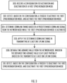
- Figure 3 depicts an example method.
- the method may be performed by a user equipment, such as the UE 120 of Figure 1 .
- the UE 120 in step 300 receives a configuration for activation and deactivation of a first synchronization (sync.) mode.
- the first synchronization mode may be also called an enhanced synchronization mode, enhanced Te mode, or Te' mode.
- the configuration may indicate at least when the UE should activate the Te' mode and when the UE should deactivate the Te' mode
- the first synchronization mode is associated with predetermined time synchronization requirements between the UE 120 and a network node, such as the gNB 110. These predetermined time synchronization conditions/requirements may be more stringent than in a second synchronization mode (also called a legacy synchronization mode, a normal synchronization mode, or a synchronization mode that is valid when the first synchronization mode is deactivated).
- the predetermined time synchronization requirements which the user equipment is required to comply with while the first synchronization mode is activated, are more stringent than while the first synchronization mode is deactivated. The more stringent time synchronization requirements may be due to application of Te'.
- the more stringent time synchronization requirements may cause or require the UE to operate differently for the reception of DL signals and/or for transmission of UL signals while in the first synchronization mode.
- the UE 120 may use a higher downlink sampling rate for detecting DL signal(s) and/or a higher uplink sampling rate for transmitting UL signal(s), than the UE would use if the first synchronization mode was deactivated.
- the UE 120 detects, based on the configuration, a trigger to activate the first synchronization mode, and activates the first synchronization mode based on the detection. In an embodiment this may denote that the second synchronization mode is deactivated when the first one is activated. There are various options on what is the configured trigger to activate the first synchronization mode.
- the UE 120 determines downlink timing based on a predetermined DL signal from the gNB 110 while the first synchronization mode is activated.
- the predetermined downlink signal occupies a higher bandwidth than a synchronization signal block (SSB). This may enable detection of the first path's time of arrival (TOA) more accurately than what would be possible with an SSB.
- TOA time of arrival
- the UE 120 may constantly track coarse (symbol level timing) and fine timing (e.g. first path of arrival) for exact knowledge of when to start sampling to receive the desired symbols.
- coarse symbol level timing
- fine timing e.g. first path of arrival
- the timing accuracy is inversely proportional to the bandwidth, so an SSB having a bandwidth close to 4 MHz this gives a timing accuracy around 250ns, whereas if the predetermined DL signal occupies 10MHz, the timing accuracy improves to around 100ns.
- the DL timing comprises determining the radio boundary (i.e. the timing when a radio frame starts).
- the UE 120 determines when the symbol starts/ends and then the UE may extrapolate to detect when the frame starts/ends. This may be done, in an embodiment, with more accuracy than in the second synchronization mode or when the first mode is deactivated.
- the UE may apply a time of arrival detection at least for the detection of the predetermined downlink signal with a higher downlink sampling rate than a downlink sampling rate used when the first synchronization mode is deactivated. I.e. the downlink sampling rate is increased during the first synchronization mode compared to the second synchronization mode.
- the change in the downlink sampling rate may be from e.g. 7,68MHz to 30,72MHz as what would correspond to receiving an SSB with 15kHz (1 sample per subcarrier per symbol) and then what is needed to receive a e.g. 20MHz RS.
- the UE 120 gradually adjusts DL timing to comply with predetermined synchronization requirements of the first synchronization mode. For example, when the transmission timing error between the UE and the reference timing exceeds ⁇ T e then the UE is required to adjust its timing to within ⁇ T e .
- the reference timing shall be ( N TA + N TA offset ) ⁇ T c before the downlink timing of the reference cell.
- the predetermined DL signal comprise a channel state information reference signal (CSI-RS), a tracking reference signal (TRS), or a positioning reference signal (PRS), or another reference signal (RS), such as demodulation reference signal (DMRS).
- CSI-RS channel state information reference signal
- TRS tracking reference signal
- PRS positioning reference signal
- RS positioning reference signal
- DMRS demodulation reference signal
- the predetermined DL signal with the higher bandwidth may be sent only when the UE 120 is in the Te' mode.
- the UE 120 applies the determined downlink timing in transmitting at least one uplink signal.
- the UL signal may be e.g. sounding reference signal (SRS) or another specified reference signal (RS).
- the predetermined UL signal may comprise a PUCCH and/or PUSCH signal.
- the configuration received in step 300 may indicate the UL signal or signals on which the determined DL timing is to be applied, or the UE 120 may apply the determined DL timing to every UL transmission or UE selected uplink transmission, at least during the first synchronization mode is active.
- the UL signal(s) on which the determined DL timing is to be applied is/are configured to occupy a higher bandwidth while in the first synchronization mode.
- the UL resources for the transmission of the UL signal(s) may be provided in an UL grant from the gNB 110 in the configuration or in a separate UL grant message.
- the UE 120 generates the at least one uplink signal with a higher uplink sampling rate than an uplink sampling rate used when the first synchronization mode is deactivated.
- the first mode may affect the required UL sampling interval.
- the used uplink sampling rate may be associated with IFFT size used to generate the UL signal.
- the TA applied to advance the UL transmission would be such that the UL signal would reach the receiver at the frame boundary.
- the DL timing determination may be slightly erroneous (e.g. due to the limited sampling granularity, limited FFT size and possible multipath channel), and the UL transmission takes place at a slightly suboptimal time instant (e.g. due to the UE hardware and software implementations).
- the UE may apply the more accurate DL timing determined in the previous step to the UL transmission(s). This is shown in Figure 2B , where the timing error blocs are smaller.
- applying of the DL timing on the UL transmission may comprise determining UL transmission time at least partly based on the determined DL timing and a current TA value.
- the UE determines the UL transmission time relative to the perceived DL timing modified by an offset of the current TA value. That means that the accuracy of the DL timing directly influences the UL transmission time.
- the reception of the UL signal at the gNB 110 is more in-line with the frame timing at the gNB, as shown in Figure 2B .
- the Te requirement is tested over the air interface, and hence is also impacted by the accuracy of the UL transmission.
- the Te requirement is a function of both UL and DL frame timing accuracies.
- the UE applies the determined downlink timing also to UL transmissions after deactivating the first synchronization mode, whereas in another embodiment, the UE returns to less strict DL/UL timing requirements of the second synchronization mode when deactivating the first synchronization mode.
- the UE 120 obtains a TA value from the gNB 110, wherein the obtained TA is based on the transmitted at least one predetermined UL signal. That is, the gNB 110 may determine the TOA of the UL signal at the gNB 110, and then estimate the time offset between UL TOA and DL frame timing (i.e. frame boundary), and this offset may be used to calculate a more accurate TA value. After receiving the new TA from the gNB 110, the UE 120 may update the existing TA value based on the newly received TA value. As such, in following signaling, the more accurate TA value may be used even after deactivating the first synchronization mode.
- This step 308 may be optional. In some cases, the TA need not be updated, and in such case the UE need not receive a new TA value from the network.
- the UE 120 detects, based on the configuration, a trigger to deactivate the first synchronization mode, and deactivates the first synchronization mode. Substantially at the same time, the UE 120 may trigger the second synchronization mode on. This may allow the UE to save power, as the second synchronization mode may not require the UE to apply the higher sampling rates and may save signaling resources as the second synchronization mode may not require the signal(s) to occupy higher bandwidth.
- the UE 120 applies increased sampling rate for the particular wider bandwidth DL signal sent by the gNB 110, and then applies the more accurate DL timing at least once for an UL transmission, so that the gNB 110 can derive more accurate TA value for the UE 120.
- Figure 4 shows a method performed by the gNB 110.
- the method comprises in step 400 determining the configuration for activation and deactivation of the first synchronization mode at the UE.
- the gNB 110 provides the configuration to the UE 120.
- the first synchronization mode is associated with predetermined time synchronization requirements between the UE 120 and the gNB 110.
- the gNB 110 may be caused or required, while in the first synchronization mode, to transmit a DL signal with a higher bandwidth and/or use a higher DL sampling rate for the transmission of the DL signal, compared to when the first synchronization mode is deactivated.
- the gNB 110 may optionally also use a higher sampling rate for the detection of UL signal(s) while in the first synchronization mode, compared to the when the first synchronization mode is deactivated.
- the first synchronization mode may further require different behaviour on the gNB 110 side, so that the gNB can also comply with the more stringent timing requirements.
- the first synchronization mode is also activated and deactivated at the gNB 110, when the UE 120 is triggered to activate or deactivate the first synchronization mode, respectively.
- the gNB 110 transmits a predetermined DL signal to the UE.
- the predetermined downlink signal may be used by the UE 120 while the UE is in the first synchronization mode.
- the UE may then perform the step 304 of Figure 3 .
- the gNB 110 receives at least one predetermined UL signal from the UE (i.e. the one(s) sent by the UE in step 306 of Figure 3 ).
- the reception time of the UL signal(s) is at least partially based on the transmitted DL signal of step 404.
- the gNB 110 determines a TA value at least partially based on the received at least one UL signal, and in step 410 provides the TA value to the UE 120.
- This step 410 is optional. In some cases, the determined TA is not different enough from the existing TA value, and in such case, it need not be updated, and the gNB 110 need not send the determined TA value to the UE 120.
- UE 120 may be configured for TA-based PDC by the gNB 110. This may comprise the gNB determining that PDC is needed, e.g. meet the desired time synchronization error budget for the time synchronization service, the gNB to configure the UE to conduct PDC, and the gNB to configure the UE to apply TA/2 (not including offsetNTA) as its PD estimate (using the first or second time synchronization mode), the UE to subtract TA/2 to its absolute timestamp from referenceTimeInfo when this is received and the UE providing this compensated timestamp to higher layers and/or local phased locked loop tracking ToD.
- OffsetNTA here is for TDD operations to capture the timing offset between UL and DL symbols that is not a part of the propagation delay round trip time, but captures switching times, guard periods, frame structure offsets, etc.
- the gNB 110 determines the configuration for the first synchronization mode.
- the configuration may comprise at least the activation criteria (here it is when the UE receives DL RS, but this is merely one option, as will be described later) and the deactivation criteria (here the UE 120 deactivates the mode when it receives an enhanced TA granularity command, but other options are possible, as will be described later).
- the gNB 110 may also determine, for the configuration and at least in this specific example of Figure 5 , the predetermined DL RS that is to be used for the Te' mode.
- This predetermined DL signal may comprise, for example, CSI-RS for tracking (TRS) with 10MHz bandwidth, identified by a CSI-RS configuration ID (denoted csi-ResourceConfigId).
- the gNB 110 may further determine, for the configuration and at least in this specific example of Figure 5 , the predetermined UL signal on which the UE applies the Te' and more accurate DL timing.
- This UL signal can be e.g. sounding reference signal (SRS).
- the gNB 110 transmits the configuration to the UE 120. This can be sent as MAC or RRC signaling, for example.
- the gNB 110 transmits and the UE 120 receives the dedicated DL signal, e.g. DL RS associated with Te'. In this example, this triggers the activation of the enhanced Te mode at the UE 120 in step 508.
- the UE would be configured to receive CSI-RS (as an example) and by configuration the UE 120 may know that it needs to activate the enhanced Te mode when receiving this. That means that the enhanced Te mode applies with the CSI-RS signal. Consequently, the UE 120 may apply the increased DL sampling rate in the reception of the DL signal, and in this way determine in step 510 the DL timing more accurately than if the first mode was deactivated.
- the configuration received in step 504 further comprises an indication of the predetermined downlink signal.
- the UE 120 transmits a predetermined UL signal.
- the UE having activated the Te' mode, complies with stricter timing error Te' requirement when transmitting the UL signal. This may comprise the UE 120 applying the determined DL timing on the transmission time of the UL signal, and the UE applying increased UL sampling rate. In an embodiment, these more stringent UL transmission criteria may apply to all subsequent UL transmissions which apply TA, until the Te' mode is disabled. These may comprise transmissions on PUSCH, PUCCH and SRS, for example.
- the configuration received in step 504 comprises an indication of the at least one uplink signal for which the determined downlink timing is to be applied.
- the gNB 110 after receiving the UL signal in step 512, estimates the timing offset between UL TOA and DL frame timing. This may be then used in calculation of the TA value. The gNB 110 may then determine if an adjustment in the UE's current TA value is needed or not.
- the gNB 110 in step 516 signals TA to the UE 120.
- the TA may have enhanced accuracy because of more time accurate performance of the UE in the detection of the DL signal in step 506 and/or in the transmission of the UL signal in step 512, and also possibly because the gNB 110 may also be configured to sample the UL signal transmitted in step 512 with an increased sampling rate compared to when the first synchronization mode is deactivated.
- the gNB 110 may decide to transmit the enhanced TA command.
- the gNB 110 may decide to transmit the legacy TA command. In an embodiment, it is specified when the enhanced TA command is used. E.g. a TA command received when the first mode is active is by default with the enhanced TA granularity. Then, the UE 120 may update its current TA value based on the newly received value.
- the UE 120 disables the Te' mode, meaning that the UE 120 does not have to comply with Te' anymore and can resume normal operation (e.g. second synchronization mode).
- the deactivation of the Te' mode takes place at the obtaining of the new TA value. If signaling the new TA value is not needed, the gNB may use another means, such as implicit signaling, to deactivate the Te' mode.
- the gNB 110 may further signal referenceTimeInfo to the UE 120 in step 520.
- This referenceTimeInfo may comprise indication of gNB's clock time that corresponds to the ending boundary of a specific radio system frame (refSFN).
- refSFN radio system frame
- the UE 120 associates the time information with its own refSFN boundary. Thereafter, in step 522, the UE 120 applies PDC using TA/2 (without offsetNTA), and conducts PDC on the referenceTimeInfo.
- Figure 6 shows another signaling flow diagram.
- Figure 6 shows some optional embodiments.
- the reference numerals that are the same in Figures 5 and 6 represent same functions. The functions of these blocks in Figure 6 will not be explained again in connection of Figure 6 , but the reader will find those above in description of Figure 5 .
- the gNB 110 may in step 600 determine channel conditions between the gNB 110 and the UE 120, and decide based on that determination whether to enable activation of the first synchronization mode at the UE. For example, before enabling the Te' mode, the gNB 110 may assess channel conditions towards the UE 120. The determination of the channel conditions may be based on measuring uplink signals, such as SRS, PUSCH and/or PUCCH. If the gNB concludes the SNR/SINR to the target UE 120 is below a certain threshold (e.g. in case the UE 120 is at cell edge or severely interfered), the gNB 110 may not trigger the enhanced Te mode, since it is expected that the UE cannot benefit from it. In other words, the conditions are assessed to be too poor for the UE 120 to benefit from the higher bandwidth reference signals. In such case, the rest of the steps in the signaling flow diagram of Figure 6 may not take place.
- the uplink signals such as SRS, PUSCH and/or PUCCH.
- the gNB 110 may in step 602 decide to enable early deactivation request of the first synchronization mode at the UE 120 when a predetermined condition is met (at the UE). For example, the gNB 110 may assess in this step whether the UE 120 can be enabled to request an early deactivation of the Te' mode, e.g. when the UE 120 e.g. experiences power shortage, and/or concludes that the Te' mode was not beneficial in reducing the error.
- the assessment at the gNB 110 may be based on at least one of the following: the UE type, UE processing capabilities (e.g. in case the UE reported advanced processing availability, the UE can be enabled with this functionality of requesting early deactivation), or UE channel conditions (e.g. a fast moving UE should be allowed to request an early deactivation, if the UE 120 cannot support fast enough spatial Te adaptation).
- step 604 the UE 120 is provided with an indication that early deactivation request is allowed when the predetermined condition is met at the UE 120, and the UE 120 may thus receive, from the gNB 110, a permission for requesting deactivation of the first synchronization mode based on detection of a predetermined condition. If the assessment in step 602 is that the UE should not be allowed to request early deactivation, then the signaling of steps 604 and 612 would not take place.
- the UE 120 may in such situation transfer a measurement representing the condition, such as a metric indicating mode efficiency, to the gNB 110.
- the UE may be requested in step 604 to compute and report in step 612 to the gNB 110 the difference between the TOA based on SSB and that based on the CSI-RS. Then the gNB 110 may evaluate the measurement and may take the decision to deactivate the Te' mode early.
- the location of arrow 612 in the Figure 6 is merely an example and the early deactivation may take place at any time after being permitted.
- the UE which may be equipped with more than one TOA determination method, may decide to toggle between the available TOA determination methods (e.g. based on UE's own past CSI information). These may comprise e.g. standard method (low-power, low complexity) which may be e.g. cross-correlation based, and an advanced method which may comprise e.g. compressed sensing, oversampling. This is shown with step 606, where the UE may switch between the two (or more) modes.
- standard method low-power, low complexity
- an advanced method which may comprise e.g. compressed sensing, oversampling.
- the UE 120 may then in step 608 determine the difference between the downlink timing obtained with the standard method and the downlink timing obtained with the advanced method. Based on the difference, the UE 120 may in step 610 evaluate mode efficiency, e.g. between standard TOA method and advanced TOA method.
- the UE 120 may request the deactivation of the first synchronization mode based on determining that the downlink timing obtained with the first synchronization mode is less than a predetermined threshold improved over the downlink timing obtained with the second synchronization mode.
- This threshold as any other thresholds depicted in the description, may be based on simulations or empirical testing, for example.
- FIGS. 7A-7D depict embodiments for the activation of Te' mode. These may comprise:
- FIGS 8A-8E depict embodiments of deactivation of the Te' mode. These may comprise:
- Each of the activation and/or deactivation embodiments/options may be configured to the UE via the configuration is step 504. That is, the gNB 110 may decide which options to use, and then configure the UE 120 with the selected options. In some embodiments, the gNB 110 is in control of the activation e.g. by sending the predetermined DL signal, UL grant, referenceTimeInfo or the explicit indication, and in control of the deactivation e.g. by sending the TA command, referenceTimeInf, or the explicit indication, or by configuring the timer value or the UL grant for the UL signal transmission.
- the options above are not mutually exclusive.
- the proposal applies to gNB-side PDC. In another embodiment, the proposal applies to UE-side PDC.
- the first synchronization mode is applied only for the purposes of propagation delay compensation (PDC), i.e. when PDC is required or needed.
- PDC propagation delay compensation
- the UE 120 may not necessarily know when the PDC procedure starts/stops, as it is most likely a constant running dynamic process.
- the proposal uses the activation and deactivation mechanisms, that can then be aligned with the PDC procedure.
- the activation mechanism A5 and deactivation mechanism D5 may be used also if Te' mode is needed for other purposes than PDC, e.g. to force the UE to use a higher bandwidth DL RS for DL timing, which potentially can enhance the UE hold-over capability (timing precision between receptions of ToA).
- the gNB 120 may decide when to trigger the activation of the first mode and it may be an implementation specific decision.
- Some benefits of the proposed solution may comprise decreased UE power consumption. Furthermore, the enhanced TA with Te' mode enables TA-based PDC for challenging time synchronization use cases, while taking the benefits from the existing TA mechanism and avoiding the drawbacks from having to comply with Te' at all times.
- One possible implementation to the standard specifics may comprise specifying a new IE to activate PDC, a configured Te' Mode and in this example case, also the associated CSI-RS resource configuration ID.
- Other alternative DL RS signals can also be considered, such as PRS. In that case, the association is made with a DL-PRS-ResourceID.
- Te' performance requirement could be as specified as below in 7.1.2-1 of TS 38.133.
- Frequency Range SCS of RS kHz
- BW of downlink signals MHz
- BW of uplink signals MHz
- T c is the basic timing unit
- An embodiment, as shown in Figure 9 provides an apparatus 10 comprising a control circuitry (CTRL) 12, such as at least one processor, and at least one memory 14 including a computer program code (software), wherein the at least one memory and the computer program code (software), are configured, with the at least one processor, to cause the apparatus to carry out any one of the above-described processes.
- CTRL control circuitry
- the memory may be implemented using any suitable data storage technology, such as semiconductor-based memory devices, flash memory, magnetic memory devices and systems, optical memory devices and systems, fixed memory and removable memory.
- the memory may comprise a database for storing data.
- the apparatus 10 may comprise the terminal device of a communication system, e.g. a user terminal (UT), a computer (PC), a laptop, a tabloid computer, a cellular phone, a mobile phone, a communicator, a smart phone, a palm computer, a mobile transportation apparatus (such as a car), a household appliance, or any other communication apparatus, commonly called as UE in the description.
- the apparatus is comprised in such a terminal device.
- the apparatus may be or comprise a module (to be attached to the UE) providing connectivity, such as a plug-in unit, an "USB dongle", or any other kind of unit.
- the unit may be installed either inside the UE or attached to the UE with a connector or even wirelessly.
- the apparatus 10 is or is comprised in the UE 120.
- the apparatus may be caused to execute some of the functionalities of the above described processes, such as the steps of Figure 3 .
- the apparatus may further comprise a radio interface (TRX) 16 comprising hardware and/or software for realizing communication connectivity according to one or more communication protocols.
- TRX may provide the apparatus with communication capabilities to access the radio access network, for example.
- the apparatus may also comprise a user interface 18 comprising, for example, at least one keypad, a microphone, a touch display, a display, a speaker, etc.
- the user interface may be used to control the apparatus by the user.
- the control circuitry 12 may comprise a synchronization mode control circuitry 20 for determining which configuration to use at a given time, according to any of the embodiments.
- the control circuitry 12 may further comprise a timing control circuitry 22 e.g. for determining the DL timing and UL transmission time, according to any of the embodiments.
- An embodiment, as shown in Figure 10 provides an apparatus 50 comprising a control circuitry (CTRL) 52, such as at least one processor, and at least one memory 54 including a computer program code (software), wherein the at least one memory and the computer program code (software), are configured, with the at least one processor, to cause the apparatus to carry out any one of the above-described processes.
- CTRL control circuitry
- the memory may be implemented using any suitable data storage technology, such as semiconductor-based memory devices, flash memory, magnetic memory devices and systems, optical memory devices and systems, fixed memory and removable memory.
- the memory may comprise a database for storing data.
- the apparatus 50 may be or be comprised in a network node, such as in gNB/gNB-CU/gNB-DU of 5G. In an embodiment, the apparatus is or is comprised in the network node 110. The apparatus may be caused to execute some of the functionalities of the above described processes, such as the steps of Figure 4 .
- a CU-DU (central unit - distributed unit) architecture is implemented.
- the apparatus 50 may be comprised in a central unit (e.g. a control unit, an edge cloud server, a server) operatively coupled (e.g. via a wireless or wired network) to a distributed unit (e.g. a remote radio head/node).
- a central unit e.g. a control unit, an edge cloud server, a server
- the radio node may be stand-alone apparatuses communicating with each other via a radio path or via a wired connection. Alternatively, they may be in a same entity communicating via a wired connection, etc.
- the edge cloud or edge cloud server may serve a plurality of radio nodes or a radio access networks.
- the described processes may be performed by the central unit.
- the apparatus may be instead comprised in the distributed unit, and at least some of the described processes may be performed by the distributed unit.
- the execution of at least some of the functionalities of the apparatus 50 may be shared between two physically separate devices (DU and CU) forming one operational entity. Therefore, the apparatus may be seen to depict the operational entity comprising one or more physically separate devices for executing at least some of the described processes.
- the apparatus controls the execution of the processes, regardless of the location of the apparatus and regardless of where the processes/functions are carried out.
- the apparatus may further comprise communication interface (TRX) 56 comprising hardware and/or software for realizing communication connectivity according to one or more communication protocols.
- TRX may provide the apparatus with communication capabilities to access the radio access net-work, for example.
- the apparatus may also comprise a user interface 58 comprising, for example, at least one keypad, a microphone, a touch display, a display, a speaker, etc.
- the user interface may be used to control the apparatus by the user.
- the control circuitry 52 may comprise a synchronization mode configuration circuitry 60 for determining the configuration with respect to switching between synchronization modes, according to any of the embodiments.
- the control circuitry 52 may comprise a timing control circuitry 62 e.g. for determining timing advance for the UE.
- an apparatus carrying out at least some of the embodiments described comprises at least one processor and at least one memory including a computer program code, wherein the at least one memory and the computer program code are configured, with the at least one processor, to cause the apparatus to carry out the functionalities according to any one of the embodiments described.
- the computer program code when the at least one processor executes the computer program code, the computer program code causes the apparatus to carry out the functionalities according to any one of the embodiments described.
- the apparatus carrying out at least some of the embodiments comprises the at least one processor and at least one memory including a computer program code, wherein the at least one processor and the computer program code perform at least some of the functionalities according to any one of the embodiments described.
- the at least one processor, the memory, and the computer program code form processing means for carrying out at least some of the embodiments described.
- the apparatus carrying out at least some of the embodiments comprises a circuitry including at least one processor and at least one memory including computer program code. When activated, the circuitry causes the apparatus to perform the at least some of the functionalities according to any one of the embodiments described.
- circuitry refers to all of the following: (a) hardware-only circuit implementations, such as implementations in only analog and/or digital circuitry, and (b) combinations of circuits and soft-ware (and/or firmware), such as (as applicable): (i) a combination of processor(s) or (ii) portions of processor(s)/software including digital signal processor(s), software, and memory(ies) that work together to cause an apparatus to perform various functions, and (c) circuits, such as a microprocessor(s) or a portion of a microprocessor(s), that require software or firmware for operation, even if the software or firmware is not physically present.
- This definition of 'circuitry' applies to all uses of this term in this application.
- the term 'circuitry' would also cover an implementation of merely a processor (or multiple processors) or a portion of a processor and its (or their) accompanying software and/or firmware.
- the term 'circuitry' would also cover, for example and if applicable to the particular element, a baseband integrated circuit or applications processor integrated circuit for a mobile phone or a similar integrated circuit in a server, a cellular network device, or another network device.
- At least some of the processes described may be carried out by an apparatus comprising corresponding means for carrying out at least some of the described processes.
- Some example means for carrying out the processes may include at least one of the following: detector, processor (including dual-core and multiple-core processors), digital signal processor, controller, receiver, transmitter, encoder, decoder, memory, RAM, ROM, software, firmware, display, user interface, display circuitry, user interface circuitry, user interface software, display software, circuit, antenna, antenna circuitry, and circuitry.
- the techniques and methods described herein may be implemented by various means. For example, these techniques may be implemented in hardware (one or more devices), firmware (one or more devices), software (one or more modules), or combinations thereof.
- the apparatus(es) of embodiments may be implemented within one or more application-specific integrated circuits (ASICs), digital signal processors (DSPs), digital signal processing devices (DSPDs), programmable logic devices (PLDs), field programmable gate arrays (FPGAs), processors, controllers, microcontrollers, microprocessors, other electronic units designed to perform the functions described herein, or a combination thereof.
- ASICs application-specific integrated circuits
- DSPs digital signal processors
- DSPDs digital signal processing devices
- PLDs programmable logic devices
- FPGAs field programmable gate arrays
- processors controllers, microcontrollers, microprocessors, other electronic units designed to perform the functions described herein, or a combination thereof.
- the implementation can be carried out through modules of at least one chip set
- the software codes may be stored in a memory unit and executed by processors.
- the memory unit may be implemented within the processor or externally to the processor. In the latter case, it can be communicatively coupled to the processor via various means, as is known in the art.
- the components of the systems described herein may be rearranged and/or complemented by additional components in order to facilitate the achievements of the various aspects, etc., described with regard thereto, and they are not limited to the precise configurations set forth in the given figures, as will be appreciated by one skilled in the art.
- Embodiments as described may also be carried out in the form of a computer process defined by a computer program or portions thereof. Embodiments of the methods described may be carried out by executing at least one portion of a computer program comprising corresponding instructions.
- the computer program may be in source code form, object code form, or in some intermediate form, and it may be stored in some sort of carrier, which may be any entity or device capable of carrying the program.
- the computer program may be stored on a computer program distribution medium readable by a computer or a processor.
- the computer program medium may be, for example but not limited to, a record medium, computer memory, read-only memory, electrical carrier signal, telecommunications signal, and software distribution package, for example.
- the computer program medium may be a non-transitory medium. Coding of software for carrying out the embodiments as shown and described is well within the scope of a person of ordinary skill in the art.
- a method comprising: receiving a configuration for activation and deactivation of a first synchronization mode, wherein the first synchronization mode requires a user equipment to comply with predetermined time synchronization requirements between the user equipment and a network node; detecting, based on the configuration, a trigger to activate the first synchronization mode, and activating the first synchronization mode; determining downlink timing based on a predetermined downlink signal from the network node while the first synchronization mode is activated; applying the determined downlink timing in transmitting at least one uplink signal; detecting, based on the configuration, a trigger to deactivate the first synchronization mode, and deactivating the first synchronization mode.
- a method comprising determining a configuration for activation and deactivation of a first synchronization mode at a user equipment, wherein the first synchronization mode requires the user equipment to comply with predetermined time synchronization requirements between the user equipment and a network node; providing the configuration to the user equipment; transmitting a predetermined downlink signal to the user equipment for use while the user equipment is in the first synchronization mode; receiving at least one uplink signal from the user equipment, the reception of the at least one uplink signal being at least partially based on the trans-mitted predetermined downlink signal.
- an apparatus comprising: at least one processor and at least one memory including a computer program code, wherein the at least one memory and the computer program code are configured, with the at least one processor, to cause the apparatus to: receive a configuration for activation and deactivation of a first synchronization mode, wherein the first synchronization mode requires the apparatus to comply with predetermined time synchronization requirements between the apparatus and a network node; detect, based on the configuration, a trigger to activate the first synchronization mode, and activate the first synchronization mode; determine downlink timing based on a predetermined downlink signal from the network node while the first synchronization mode is activated; apply the determined downlink timing in transmitting at least one uplink signal; detect, based on the configuration, a trigger to deactivate the first synchronization mode, and deactivate the first synchronization mode.
- Various embodiments of the third aspect may comprise at least one feature from the bulleted list under the first aspect.
- an apparatus comprising: at least one processor and at least one memory including a computer program code, wherein the at least one memory and the computer program code are configured, with the at least one processor, to cause the apparatus to: determine a configuration for activation and deactivation of a first synchronization mode at a user equipment, wherein the first synchronization mode requires the user equipment to comply with predetermined time synchronization requirements between the user equipment and the apparatus; provide the configuration to the user equipment; transmit a predetermined downlink signal to the user equipment for use while the user equipment is in the first synchronization mode; receive at least one uplink signal from the user equipment, the reception of the at least one uplink signal being at least partially based on the transmitted predetermined downlink signal.
- Various embodiments of the fourth aspect may comprise at least one feature from the bulleted list under the second aspect.
- a computer program product embodied on a distribution medium readable by a computer and comprising program instructions which, when loaded into an apparatus, execute the method according to the first aspect.
- a computer program product embodied on a distribution medium readable by a computer and comprising program instructions which, when loaded into an apparatus, execute the method according to the second aspect.
- a computer program product comprising program instructions which, when loaded into an apparatus, execute the method according to the first aspect.
- a computer program product comprising program instructions which, when loaded into an apparatus, execute the method according to the second aspect.
- an apparatus comprising means for performing the method according to the first aspect, and/or means configured to cause a user equipment to perform the method according to the first aspect.
- an apparatus comprising means for performing the method according to the second aspect, and/or means configured to cause a network node to perform the method according to the second aspect.
- the means may comprise at least one processor and at least one memory including computer program code, the at least one memory and computer program code configured to, with the at least one processor, cause the performance of the apparatus.
- a computer system comprising: one or more processors; at least one data storage, and one or more computer program instructions to be executed by the one or more processors in association with the at least one data storage for carrying out the method according to the first aspect and/or the method according to the second aspect.
Landscapes
- Engineering & Computer Science (AREA)
- Computer Networks & Wireless Communication (AREA)
- Signal Processing (AREA)
- Mobile Radio Communication Systems (AREA)
Applications Claiming Priority (1)
| Application Number | Priority Date | Filing Date | Title |
|---|---|---|---|
| US202163250306P | 2021-09-30 | 2021-09-30 |
Publications (1)
| Publication Number | Publication Date |
|---|---|
| EP4161171A1 true EP4161171A1 (fr) | 2023-04-05 |
Family
ID=83193247
Family Applications (1)
| Application Number | Title | Priority Date | Filing Date |
|---|---|---|---|
| EP22193804.6A Pending EP4161171A1 (fr) | 2021-09-30 | 2022-09-05 | Amélioration de la synchronisation |
Country Status (1)
| Country | Link |
|---|---|
| EP (1) | EP4161171A1 (fr) |
Citations (1)
| Publication number | Priority date | Publication date | Assignee | Title |
|---|---|---|---|---|
| US20170367058A1 (en) * | 2014-12-23 | 2017-12-21 | Idac Holdings, Inc. | Latency reduction in lte systems |
-
2022
- 2022-09-05 EP EP22193804.6A patent/EP4161171A1/fr active Pending
Patent Citations (1)
| Publication number | Priority date | Publication date | Assignee | Title |
|---|---|---|---|---|
| US20170367058A1 (en) * | 2014-12-23 | 2017-12-21 | Idac Holdings, Inc. | Latency reduction in lte systems |
Non-Patent Citations (3)
| Title |
|---|
| NOKIA ET AL: "Remaining issues for accurate reference time delivery", vol. RAN WG2, no. Reno, USA; 20191118 - 20191122, 8 November 2019 (2019-11-08), XP051817296, Retrieved from the Internet <URL:https://ftp.3gpp.org/tsg_ran/WG2_RL2/TSGR2_108/Docs/R2-1915691.zip> [retrieved on 20191108] * |
| QUALCOMM INCORPORATED: "Propagation Delay Compensation for TSN", vol. RAN WG2, no. 20210125 - 20210205, 15 January 2021 (2021-01-15), XP051973467, Retrieved from the Internet <URL:https://ftp.3gpp.org/tsg_ran/WG2_RL2/TSGR2_113-e/Docs/R2-2100267.zip> [retrieved on 20210115] * |
| VIVO: "Discussion on propagation delay compensation in rel-16", vol. RAN WG2, no. Electronic Meeting; 20200228 - 20200306, 14 February 2020 (2020-02-14), XP051849070, Retrieved from the Internet <URL:https://ftp.3gpp.org/tsg_ran/WG2_RL2/TSGR2_109_e/Docs/R2-2000490.zip> [retrieved on 20200214] * |
Similar Documents
| Publication | Publication Date | Title |
|---|---|---|
| KR102676172B1 (ko) | 무선 통신들에 대한 시간 동기화 | |
| CN111316723B (zh) | 开环上行链路定时提前 | |
| CN113412653B (zh) | 支持针对透明和边界时钟的无线通信增强的方法和设备 | |
| CN110999125B (zh) | 通信装置、通信控制方法和计算机程序 | |
| CN113196810A (zh) | 用于移动网络中的移动性的方法和装置 | |
| EP2704463B1 (fr) | Procédé et dispositif de transmission de données | |
| AU2017308902A1 (en) | Timing advance and processing capabilities in a reduced latency system | |
| US10165455B2 (en) | Coordination for PBCH | |
| US20170373907A1 (en) | Use of frequency offset information for wireless networks | |
| CN109155980B (zh) | 与ul cca下的多载波系统中的传输定时差相关的系统和方法 | |
| EP3678441B1 (fr) | Amélioration de la procédure d'accès | |
| EP4161171A1 (fr) | Amélioration de la synchronisation | |
| CA3235386A1 (fr) | Adaptation de mobilite sous couverture discontinue | |
| CN116210284A (zh) | 用于为了功率节省而管理上行链路发送的技术 | |
| CN116134882A (zh) | 测量报告定时调整 | |
| EP4443991A1 (fr) | Détermination du temps de propagation aller-retour dans un ntn | |
| WO2022210023A1 (fr) | Équipement utilisateur et procédé de commande de communication | |
| US20240349215A1 (en) | Performing propagation delay compensation | |
| WO2024207189A1 (fr) | Attribution de ressources communes pour des économies d'énergie d'ue dans jcs | |
| US20240089023A1 (en) | Concurrent code division and frequency division signaling via an uplink channel | |
| WO2023098854A1 (fr) | Procédé et appareil de synchronisation pour rach et sdt dans dl bwp sans ssb | |
| US20240121728A1 (en) | Method for determining propagation delays | |
| WO2024060264A1 (fr) | Considérations de partie de bande passante pour une radio principale assistée par une radio de réveil à faible puissance | |
| US20230370233A1 (en) | Probability indication for interference management | |
| JP2024533961A (ja) | Rrc非アクティブモード及びアイドルモードにおけるprsと他のチャネルとの間のソフト衝突 |
Legal Events
| Date | Code | Title | Description |
|---|---|---|---|
| PUAI | Public reference made under article 153(3) epc to a published international application that has entered the european phase |
Free format text: ORIGINAL CODE: 0009012 |
|
| STAA | Information on the status of an ep patent application or granted ep patent |
Free format text: STATUS: THE APPLICATION HAS BEEN PUBLISHED |
|
| AK | Designated contracting states |
Kind code of ref document: A1 Designated state(s): AL AT BE BG CH CY CZ DE DK EE ES FI FR GB GR HR HU IE IS IT LI LT LU LV MC MK MT NL NO PL PT RO RS SE SI SK SM TR |
|
| STAA | Information on the status of an ep patent application or granted ep patent |
Free format text: STATUS: REQUEST FOR EXAMINATION WAS MADE |
|
| 17P | Request for examination filed |
Effective date: 20231005 |
|
| RBV | Designated contracting states (corrected) |
Designated state(s): AL AT BE BG CH CY CZ DE DK EE ES FI FR GB GR HR HU IE IS IT LI LT LU LV MC MK MT NL NO PL PT RO RS SE SI SK SM TR |